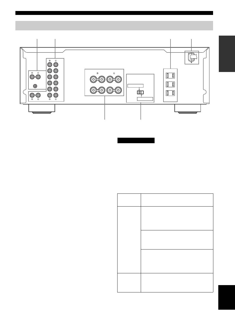
Yamaha AX-497: Rear panel
Rear panel: Yamaha AX-497
Table of contents
- CAUTION: READ THIS BEFORE OPERATING YOUR UNIT.
- FEATURES SUPPLIED ACCESSORIES
- POWER CONTROLS AND FUNCTIONS Front panel
- VOLUME Opening and closing the front panel door
- Remote control
- Installing batteries in the remote control Using the remote control
- Rear panel
- Connecting speakers and other components
- Connecting the banana plug (With the exception of Asia, Korea, U.K. and
- Connecting the power supply cord
- Play the source. Playing a source
- Press STANDBY/ON on the front panel again
- Adjusting the tonal quality
- Recording a source to a tape or an MD
- AX-397
- General TROUBLESHOOTING Problem
- Remote control Problem
- SPECIFICATIONS
CONTROLS AND FUNCTIONS
7
INTR
ODUCTION
English
1
PHONO jacks and GND terminal
See page 8 for connection information.
2
Audio input/output jacks
See page 8 for connection information.
3
AC OUTLET(S)
Use to supply power to your other audio/video
components.
See page 10 for details.
4
AC power supply cord
See page 10 for connection information.
5
SPEAKERS terminals
Connect one or two speaker sets.
See page 8 for connection information.
6
IMPEDANCE SELECTOR
See “IMPEDANCE SELECTOR switch” on this page.
■
Asia and General models only
VOLTAGE SELECTOR is only applicable to the Asia and
General models.
VOLTAGE SELECTOR
See page 10 for details.
■
IMPEDANCE SELECTOR switch
Do not change the IMPEDANCE SELECTOR switch
while the power of this unit is turned on, as doing so may
damage the unit.
If this unit fails to turn on, the IMPEDANCE SELECTOR
switch may not be fully slid to either position. If this is the
case, slide the switch all the way to either position when
this unit’s power supply is completely cut off.
Select the switch position (left or right) according to the
impedance of the speakers in your system.
Rear panel
AC OUTLETS
IMPEDANCE SELECTOR
SPEAKERS
TUNER
TAPE
IN
(PLAY)
OUT
(REC)
MD
AUX
GND
PHONO
CD/DVD
IN
(PLAY)
OUT
(REC)
SWITCHED
100W MAX. TOTAL
+
+
A
B
–
–
A OR B: 4
Ω
MIN / SPEAKER
A+B: 8
Ω
MIN / SPEAKER
A OR B: 6
Ω
MIN / SPEAKER
5
1
2
3
4
6
(U.S.A. model)
Switch
position
Impedance level
Right
Asia model
• If you use one set (A or B), the impedance of
each speaker must be 8
Ω
or higher.
• If you use two sets (A and B), the impedance
of each speaker must be 16
Ω
or higher.
Canada model
• You can use one set (A or B), and the
impedance of each speaker must be 6
Ω
or
higher.
Other models
• If you use one set (A or B), the impedance of
each speaker must be 6
Ω
or higher.
• If you use two sets (A and B), the impedance
of each speaker must be 12
Ω
or higher.
Left
• If you use one set (A or B), the impedance of
each speaker must be 4
Ω
or higher.
• If you use two sets (A and B), the impedance
of each speaker must be 8
Ω
or higher.
CAUTION
