
Electrolux EFP60241X: INSTALLATION
INSTALLATION : Electrolux EFP60241X
INSTALLATION
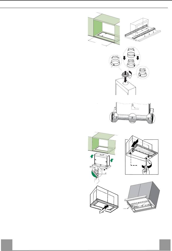
Drilling the Support surface and Fitting the Hood
• The Hood can be fitted directly on the
lower surface of the Wall Units (650 mm
1
min. above the Cooker Top) using the snap-
on Side Supports.
• Make an opening on the lower surface of
the Wall Unit, as indicated. (fig.1)
162
• Before carrying out the installation, the
523
wooden transportation protections screwed
on the visor and on the canopy body must
be removed. (fig.2)
• Choose the correct flange measure basing
on the air outlet diameter and insert it to the
upper air outlet opening. (fig.3)
• Screw the closing profile 20 onto the rear
part of the hood, using the screws 12f (2.9
x 9.5) provided. (fig.4)
• Open the sliding suction panel.
• Remove the metal grease filters one by one
after having disconnected the relative fas-
tening elements.
• Close the sliding suction panel again.
• Insert the Hood until the snap-on side sup-
ports click into place. (fig.5)
• Open the sliding suction panel.
• Lock in position by tightening the screws
Vf from underneath the Hood. (fig.5)
• If necessary, adjust the whole filter holder
unit and proceed as follows:
• Loosen the four adjustment screws Vr
and close the sliding panel again. (fig.6)
• Move the entire filter holder unit until it
is properly aligned with the wall unit.
(fig.7)
• Keeping the hood canopy still, remove
the sliding panel and lock the adjustment
screws again. (fig.6)
• The hood can now be fastened to the
wall unit using the four screws 12a (3.5
x 16) provided. (fig.8)
• Replace the metal grease filters.
• Close the sliding suction panel again.
6
EN
6
2
10b
10a
9
10a
3
5
Vr
6
7
12a
8
4
Connections
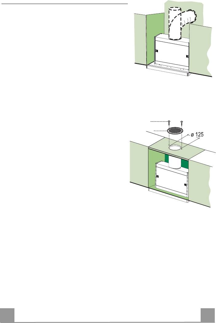
DUCTING VERSION AIR EXHAUST SYSTEM
When installing the hood in ducting version, a rigid or a
flexible pipe with the diameter corresponding to the
flange diameter is used in order to connect the hood to
the air outlet piping.
• Fix the pipe with an adequate quantity of pipe
clamps (not supplied).
• Remove possible charcoal filters.
RECIRCULATION VERSION AIR OUTLET
12e
• Cut a hole ø 125 mm in any shelf that may be posi-
8
tioned over the hood.
• Insert the flange 10a on the hood body outlet.
• Connect the flange to the outlet on the shelf over the
hood using a flexible or rigid pipe ø120 mm.
• Fix the pipe in position using sufficient pipe clamps
(not supplied).
• Fix the directional grille 8 on the recirculation air
outlet using the 2 screws 12e (2,9 x 12,7) provided.
• Ensure that the activated charcoal filters have been
inserted.
ELECTRICAL CONNECTION
• Connect the hood to the mains through a two-pole switch having a contact gap of at least 3
mm..
7
EN
7
Table of contents
- Instructions Manual Manuel d’Instructions Bedienungsanleitung Gebruiksaanwijzing Руководство по эксплуатации Bruksanvisning
- INDEX
- INDHOLD
- RECOMMENDATIONS AND SUGGESTIONS
- CHARACTERISTICS
- INSTALLATION
- USE
- MAINTENANCE
- CONSEILS ET SUGGESTIONS
- CARACTERISTIQUES
- INSTALLATION
- UTILISATION
- ENTRETIEN
- EMPFEHLUNGEN UND HINWEISE
- CHARAKTERISTIKEN
- MONTAGE
- BEDIENUNG
- WARTUNG
- ADVIEZEN EN SUGGESTIES
- EIGENSCHAPPEN
- INSTALLATIE
- GEBRUIK
- ONDERHOUD
- СОВЕТЫ И РЕКОМЕНДАЦИИ
- ХАРАКТЕРИСТИКИ
- УСТАНОВКА
- ЭКСПЛУАТАЦИЯ
- УХОД
- REKOMMENDATIONER OCH TIPS
- EGENSKAPER
- INSTALLATION
- ANVÄNDING
- UNDERHÅLL
- RÅD OG ANVISNINGER
- APPARATBESKRIVELSE
- INSTALLATION
- BRUG
- VEDLIGEHOLDELSE


