ABUS TVIP52502 Operating instructions – page 5
Manual for ABUS TVIP52502 Operating instructions
Table of contents
- User manual
81
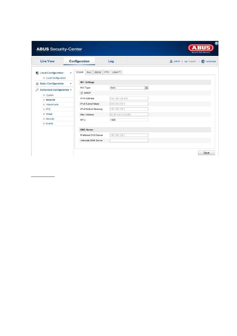
10.3.2.1 TCP/IP
To be able to operate the Speed Dome via a network, the TCP/IP settings must be configured correctly.
NIC Settings
NIC Type
Select the setting for your network adapter.
You can choose from the following values: 10M Half-dup; 10M Full-dup; 100M Half-dup;
100M Full-dup; 10M/100M/1000M Auto
DHCP
If a DHCP server is available, click DHCP to apply an IP address and other network settings automatically.
The data is transferred automatically from the server and cannot be changed manually.
If no DHCP server is available, please enter the following data manually.
IPv4 Address
Setting for the IP address of the Speed Dome
IPv4 Subnet Mask
Manual setting of the subnet address for the Speed Dome
IPv4 Default Gateway
Setting for the default router for the Speed Dome
IPv6 mode
Manual: Manual configuration of IPv6 data
DHCP: The IPv6 connection data is provided by the DHCP server (router).
Route advertisement: The IPv6 connection data is provided by the DHCP server (router) in connection with
the ISP (Internet Service Provider).
IPv6 address
Display of the IPv6 address. The address can be configured in the IPv6 “Manual” mode.
82
IPv6 Subnet Mask
Display of the IPv6 Subnet Mask
IPv6Standard Gateway
Display of the IPv6 Standard Gateway (standard router)
MAC Address
The IPv4 hardware address of the camera is displayed here. You cannot change it.
MTU
Setting for the transmission unit. Select a value between 500 – 9676. 1500 is set by default.
DNS Server
Preferred DNS Server
DNS server settings are required for some applications (for example, sending e-mails). Enter the address
of the preferred DNS server here.
Alternate DNS Server
If the preferred DNS server cannot be reached, this alternative DNS server is used. Please store the
address of the alternate DNS server here.
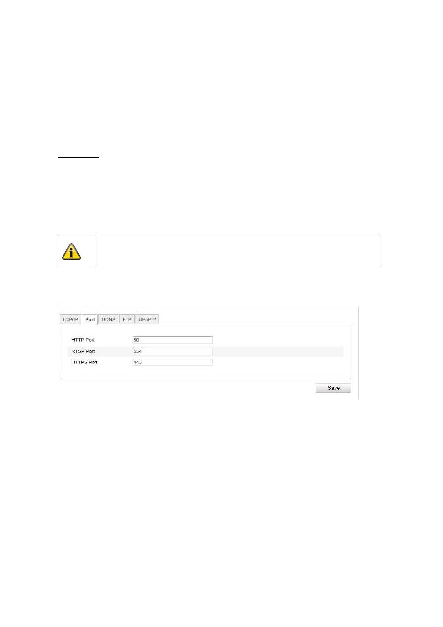
10.3.2.2 Port
If you wish to enable external access to the Speed Dome, the following ports must be configured.
HTTP Port
The standard port for HTTP transmission is 80. As an alternative, this port can be assigned a value in the
range of 1024 ~ 65535. If several Speed Domes are connected in the same subnetwork, then each
camera should be given a unique HTTP port of its own.
RTSP Port
The standard port for RTSP transmission is 554. As an alternative, this port can be assigned a value in the
range of 1024 ~ 65535. If several Speed Domes are connected in the same subnetwork, then each
camera should be given a unique RTSP port of its own.
HTTPS port
The standard port for HTTPS transmission is 443.
SDK port (control port)
The standard port for SDK transmission is 8000. Communication port for internal data. As an alternative,
this port can be assigned a value in the range of 1025 ~ 65535. If several IP cameras are located in the
same subnetwork, then each camera should have its own unique SDK port.
Apply the settings made with “Save”.
83
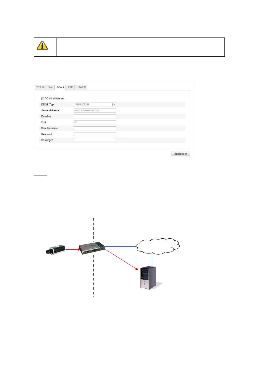
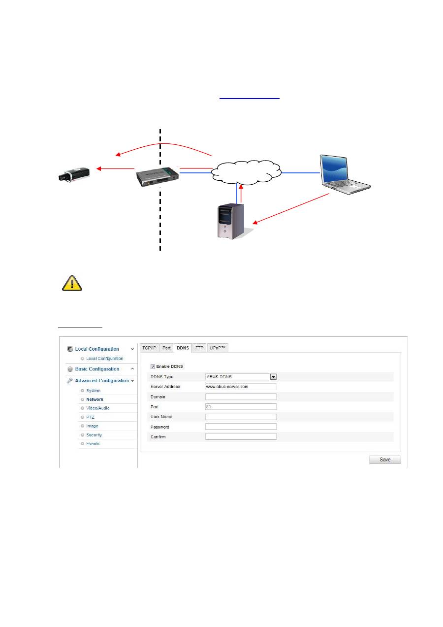
10.3.2.3 DDNS
DDNS
DynDNS or DDNS (dynamic domain name system entry) is a system that can update domain name entries
in real time. The network camera is equipped with an integrated DynDNS client that updates the IP
address independently via a DynDNS provider. If the network camera is located behind a router, we
recommend using the DynDNS function of the router.
The following diagram offers an overview of accessing and updating the IP address using DynDNS.
Apply the settings made with “Save”.
LAN
WAN
DynDNS access
data
84
Enable DDNS
Activates or deactivates the DDNS function.
DDNS Type
Select the DDNS type. You can choose between “DynDNS” and “ABUS DDNS”.
Server Address
Select a DDNS service provider. You must have registered access to this DDNS service provider (e.g.
www.dyndns.org
).
If you select “ABUS DDNS” as the DDNS type the server address is stored automatically.
Domains
Enter your registered domain name (host service) here (e.g. myIPcamera.dyndns.org).
Port
Store the port for port forwarding here.
User Name
User ID of your DDNS account
Password
Password of your DDNS account
Confirm
You need to confirm your password here.
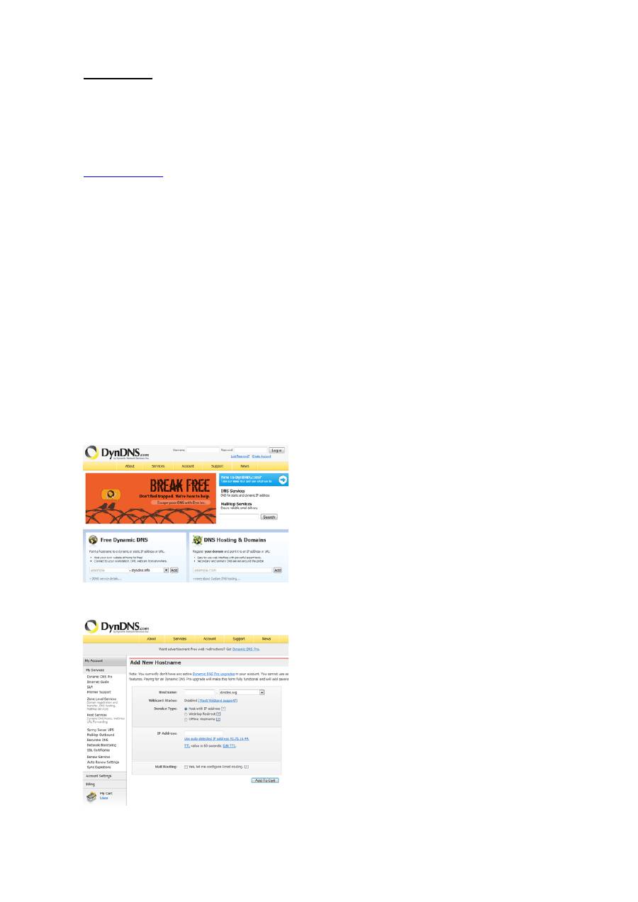
Setting up a DDNS account
Set up a new account as follows under DynDNS.org:
Store your account information:
Note down your user data and enter this into the configuration of the network camera.
85
Accessing the network camera over DDNS
If the network camera is located behind a router, then access via DynDNS must be configured in the
router. On the ABUS Security-Center homepage
www.abus-sc.com
,
you can find a description of DynDNS
router configuration for common router models.
The following diagram offers an overview of accessing a network camera behind a router via DynDNS.org.
ABUS DDNS
1. To be able to use the ABUS DDNS function, you first need to set up an account at www.abus-
server.com. Please read the FAQs on this topic on the website.
2. Select the “Enable DDNS” checkbox and select “ABUS DDNS” as the DDNS type.
3. Apply the data with
“Save”
. The IP address of your Internet connection is now updated every minute
on the server.
Port forwarding of all relevant ports (at least RTSP + HTTP) must be set up in the
router in order to use DynDNS access via the router.
DynDNS.org
Name Server
http://name.dyndns.org:1026
name.dyndns.org:1026
195.184.21.78:1026
195.184.21.78:1026
195.184.21.78:1026
192.168.0.1
LAN
WAN
Internet
86
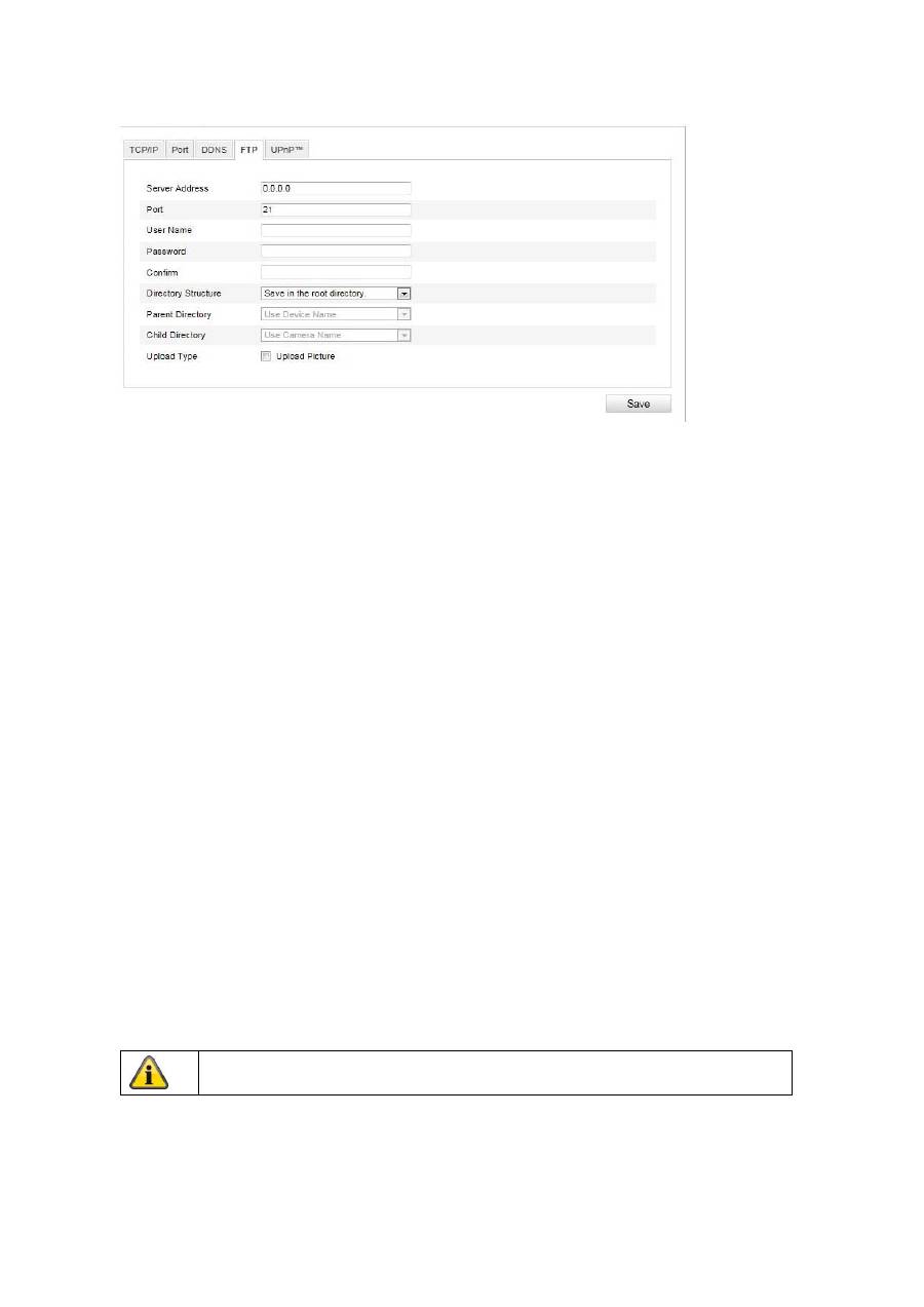
10.3.2.4 FTP
To upload recorded videos or images onto an FTP server, the following settings must be made.
Server Address
Enter the IP address of the FTP server.
Port
Enter the port number of the FTP server. The standard port for FTP servers is 21.
User Name
User name of the account that was configured in the FTP server.
Password
Password of the account that was configured in the FTP server.
Confirm
Reenter the password here.
Directory Structure
Select the storage location for the uploaded data here. You can select between:
“Save in the root directory”; “Save in the parent directory”; “Save in the child directory”.
Parent Directory
This menu item is only available if “Save in the parent directory” or “Save in the child directory” was
selected under “Directory Structure”. You can select the name for the parent directory here. The files are
saved in a folder on the FTP server.
Choose between “Use Device Name”, “Use Device Number” and “Use Device IP address”.
Child Directory
Select the name for the child directory here. The folder is created in the parent directory. You can choose
between “Use Camera Name” of “User Camera Number”.
Upload Type
Select “Upload Picture” to upload pictures to the FTP server.
Apply the settings made with “Save”.
87
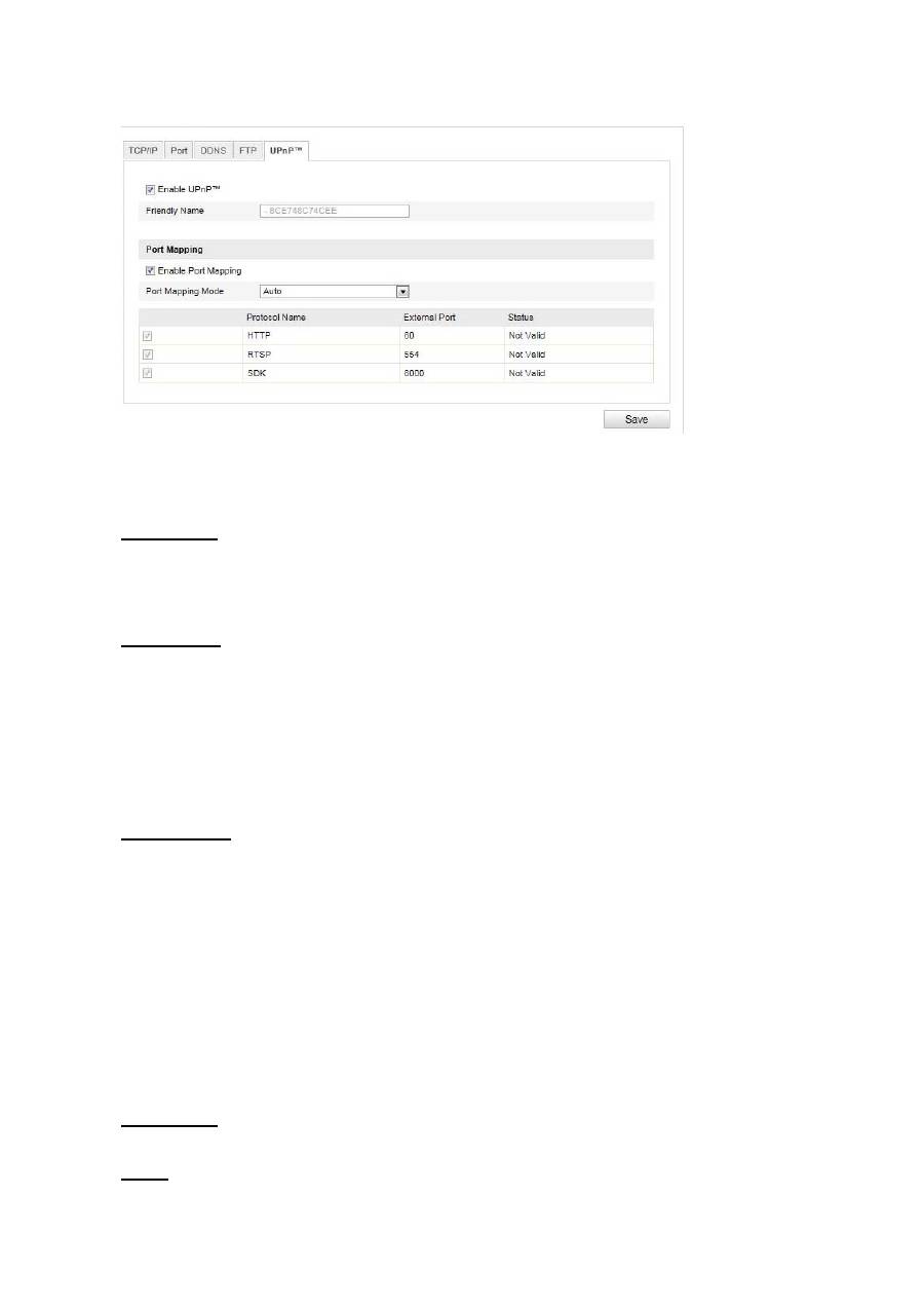
10.3.2.5 UPnP™
The UPnP (Universal Plug and Play) function makes it easy to control network devices in an IP network.
This allows the network camera to be seen in the Windows network environment (e.g. as a network
device).
Enable UPnP
For enabling or disabling the UPnP function.
Friendly Name
Display of the MAC address of the camera
Port Mapping
Enable Port Mapping
This enables Universal Plug and Play port forwarding for network services. If your router supports UPnP,
then port forwarding for video streams is activated automatically on the router for the network camera
using this option.
Port Mapping Mode
Select here whether you wish to conduct port mapping automatically or manually.
You can choose between “Auto” and “Manual”.
Protocol Name
HTTP
The standard port for HTTP transmission is 80. As an alternative, this port can be assigned a value in the
range of 1025 ~ 65535. If several IP cameras are located on the same subnetwork, then each camera
should have its own unique HTTP port.
RTSP
The standard port for RTSP transmission is 554. As an alternative, this port can be assigned a value in the
range of 1025 ~ 65535. If several IP cameras are located in the same subnetwork, then each camera
should have its own unique RTSP port.
SDK (control port)
The standard port for SDK transmission is 8000. Communication port for internal data. As an alternative,
this port can be assigned a value in the range of 1025 ~ 65535. If several IP cameras are located in the
same subnetwork, then each camera should have its own unique SDK port.
External Port
You can only change ports manually here of the “Port Mapping Mode” was set to manual.
Status
Displays whether the external port entered is valid or invalid.
88
10.3.3 Video / Audio
Menu item
Description
Available in mode
Video
Settings for video output
Basic Configuration,
Advanced
Configuration
Audio
Settings for audio output
Basic Configuration,
Advanced
Configuration
Apply the settings made with “Save”.
89
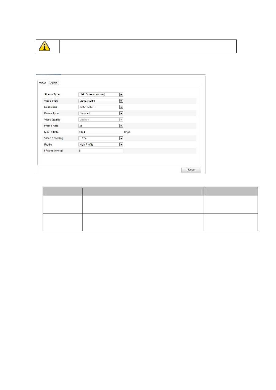
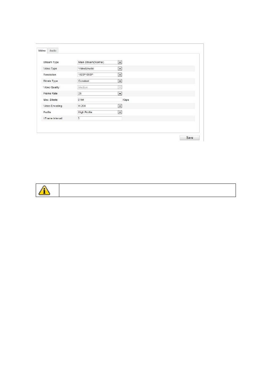
10.3.3.1 Video
Stream Type
Select the stream type for the Speed Dome camera. Select “Main Stream (Normal)” for recording and live
view with a good bandwidth. Select “Sub Stream” for live view with restricted bandwidth.
Video Type
Select either “Video” or “Video&Audio” for the stream type.
Resolution
Set the resolution of the video data here. Depending on the camera model you can choose from between
1280*720P; 1280*960; 1920*1080P.
Bitrate Type
Specifies the bit rate of the video stream. The video quality can be higher or lower depending on the
intensity of the motions.You can select between a constant and variable bit rate.
Video Quality
This menu item is only available if you have selected a variable bit rate. Set the video quality for video data
here.The video quality can differ depending on the intensity of movement. You can select from six different
video qualities: “Lowest” “Lower”, “Low”, “Medium”, “Higher” or “Highest”.
Frame Rate
Specifies the frame rate in frames per second.
Max. Bitrate
The bit rate of the video stream is set to a certain value. Set a maximum bit rate of between 32 and 16384
Kbps. A higher value means better video quality, however, this requires more bandwidth.
Video Encoding
Select a standard for video encoding. You can choose between H.264, MPEG4 and MJPEG
Profile
Select a profile here. You can choose between “Basic Profile”, “Main Profile” and “High Profile”.
I Frame Interval
Set the I frame interval here. The value must lie between 1 – 400.
The audio signal is only recorded if you select “Video&Audio” as the stream type.
90
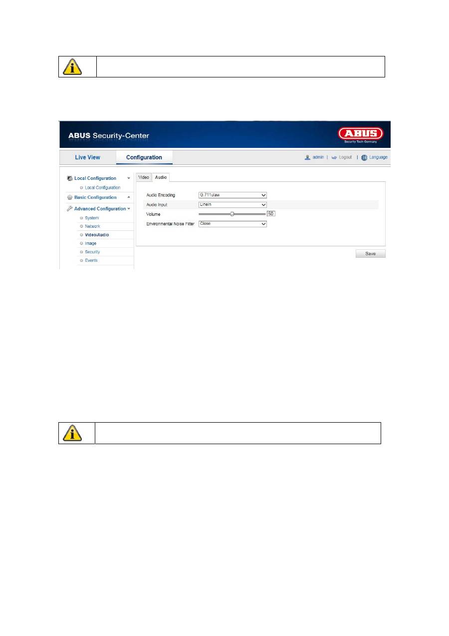
10.3.3.2 Audio
Audio coding
Select the encoding for audio transmission here.
You can choose between “G.711ulaw”, “G.711alaw” and “G.726”.
Audio input
MicIn: The settings for the audio input on the back of the camera are customised to a microphone
(unamplified source).
LineIn: The settings for the audio input on the back of the camera are customised to a line signal (active
amplified source).
Volume
Adjusting the input signal.
Noise filter
Activating or deactivating the noise filter for background noise
Apply the settings made with “Save”.
Apply the settings made with “Save”.
91
11.3.4 Image
Menu item
Description
Available in mode
Display Settings
Displaying parameter settings
Basic Configuration,
Advanced
Configuration
OSD Settings
Settings for the date and time formats
Advanced
Configuration
Text Overlay
Adding text fields
Advanced
Configuration
Privacy masking
Adding privacy masking
Advanced
Configuration
92
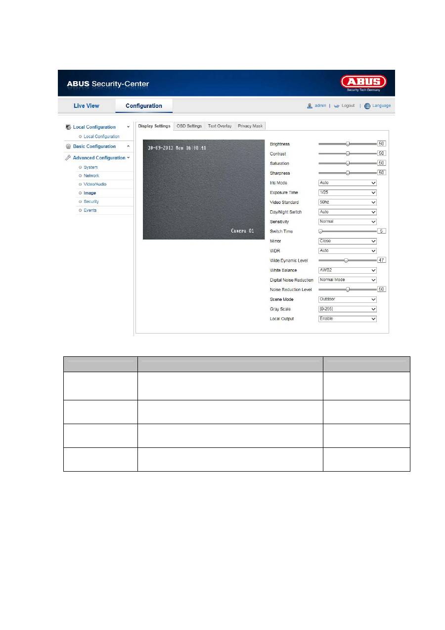
10.3.4.1 Display Settings
You can use this menu item to set the picture quality of the Speed Dome, including brightness, sharpness,
contrast and so on. Click on “Default” to restore the default values.
Please note:
The display setting parameters can vary depending on the model.
Brightness
Image brightness settings. A value between 0 and 100 can be set.
Contrast
Image contrast settings. A value between 0 and 100 can be set.
Saturation
Image saturation settings. A value between 0 and 100 can be set.
Limit Gain
Setting for the maximum limit gain. A value between 0 and 100 can be set.
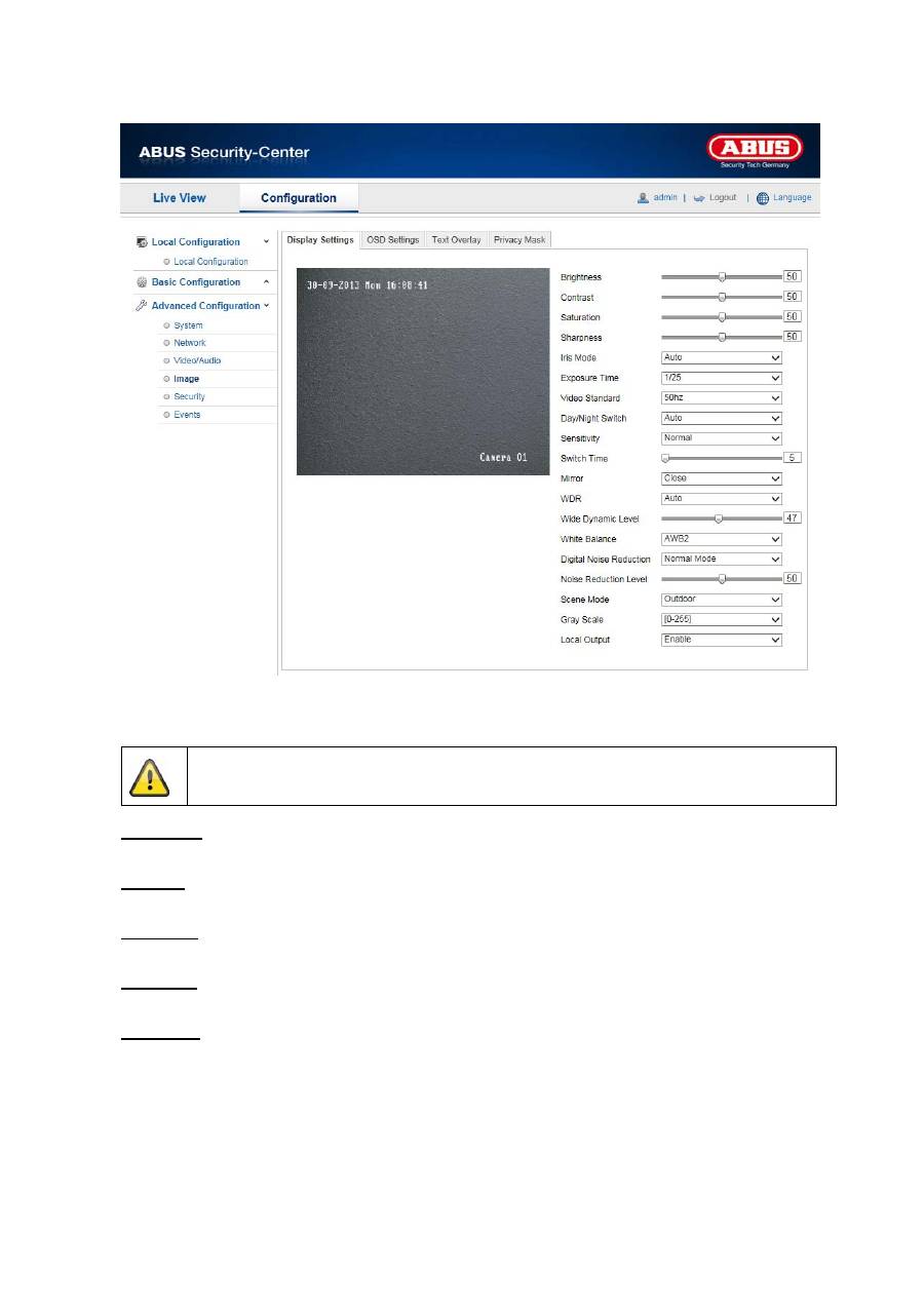
Sharpness
Image sharpness settings. A higher sharpness value can increase image noise.
A value between 0 and 100 can be set.
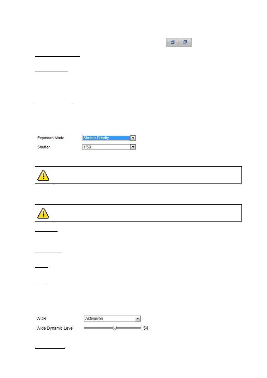
Exposure mode
Automatic or manual adjusting of exposure parameters.
Auto
The Speed Dome camera focuses automatically depending on the objects in the scene.
93
Manual
The camera has to be focussed manually using the zoom buttons
.
Duration of exposure
Setting the maximum exposure time. This setting is dependent on iris mode.
Video Standard
Setting for the exposure frequency
50Hz: fixed setting to 50 Hz network frequency
60Hz: fixed setting to 60 Hz network frequency
Day/Night Switch
Day/Night Switch Provides options for “Day”, “Night” and “Auto”.
Auto
Depending on the light conditions, the camera switches between day and night mode automatically. The
sensitivity can be set between “Low”, “Normal” and “High”.
Day
In this mode, the camera only outputs colour pictures.
Please note:
Only use this mode if the light conditions remain constant.
Night
In this mode, the camera only outputs black/white and pictures.
Please note:
Only use this mode if the light conditions are poor.
Sensitivity
Setting for the switching threshold for automatic day/night switching (Low, Normal, High).
A lower value means that there is a lower lighting level for switching to night mode.
Switch Time
Setting a delay time between recognising that a switching is required and carrying out the process.
Mirror
If the mirror function is active, the image is mirrored horizontally.
WDR
With the aid of the WDR function, the camera can return clear pictures even in disadvantageous backlight
conditions. If there are both very bright and very dark areas in the picture area, the brightness level of the
overall picture is balanced to provide a clear, detailed image.
Click on the checkbox to activate or deactivate the WDR function.
Set the Wide Dynamic Level higher to enhance the WDR function.
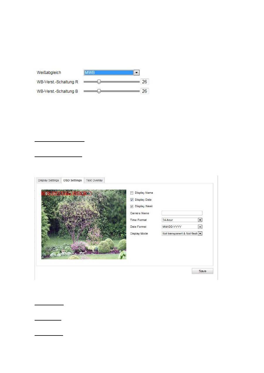
White balance
94
Here you select the lighting conditions in which the camera is installed.
You can choose from the following options: “MWB”, “AWB1”, “AWB2”, “WB Locked”, “Florescent Lamp”,
“Standard Lighting”, “Warm Lighting”, “Natural Lighting”.
MWB
You can adjust the white balance with the following values manually.
WB locked
The white balance is performed once and saved.
Others
Use additional white balance options to adjust the function to the light levels.
Digital Noise Reduction
You can activate (normal mode) or deactivate the noise reduction here.
Noise Reduction Level
Set the level for noise reduction here.
10.3.4.2 OSD Settings
You can use this menu item to select which date and time format are displayed in the live picture.
Display Name
Activate this checkbox if you wish to display the camera name.
Display Date
Activate this checkbox if you wish to display the date in the camera image.
Display Week
Activate this checkbox if you wish to display the day of the week.
95
Camera Name
Enter the camera name that is to be displayed in the image here.
Time Format
Choose here whether you would like to display the time in 24-hour or 12-hour format.
Date Format
Select the format for the date display here.
(M = month; D = day; Y = year)
Display Mode
Here you can select the display mode for the elements displayed.
You have the following options: “Transparent & Flashing”, “Transparent & Not flashing”, “Not transparent &
Flashing”, “Not transparent & Not flashing”.
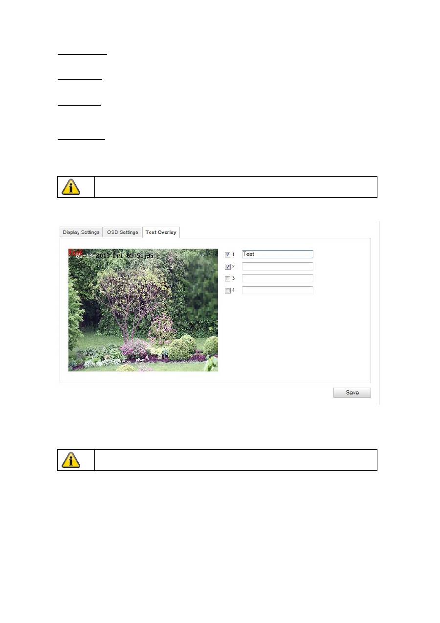
10.3.4.3 Text Overlay
You can display up to four texts in the camera image. The maximum length for the texts is 45 characters.
To display the text, activate the checkbox.
You can move the text window with the mouse.
Apply the settings made with “Save”.
Apply the settings made with “Save”.
96
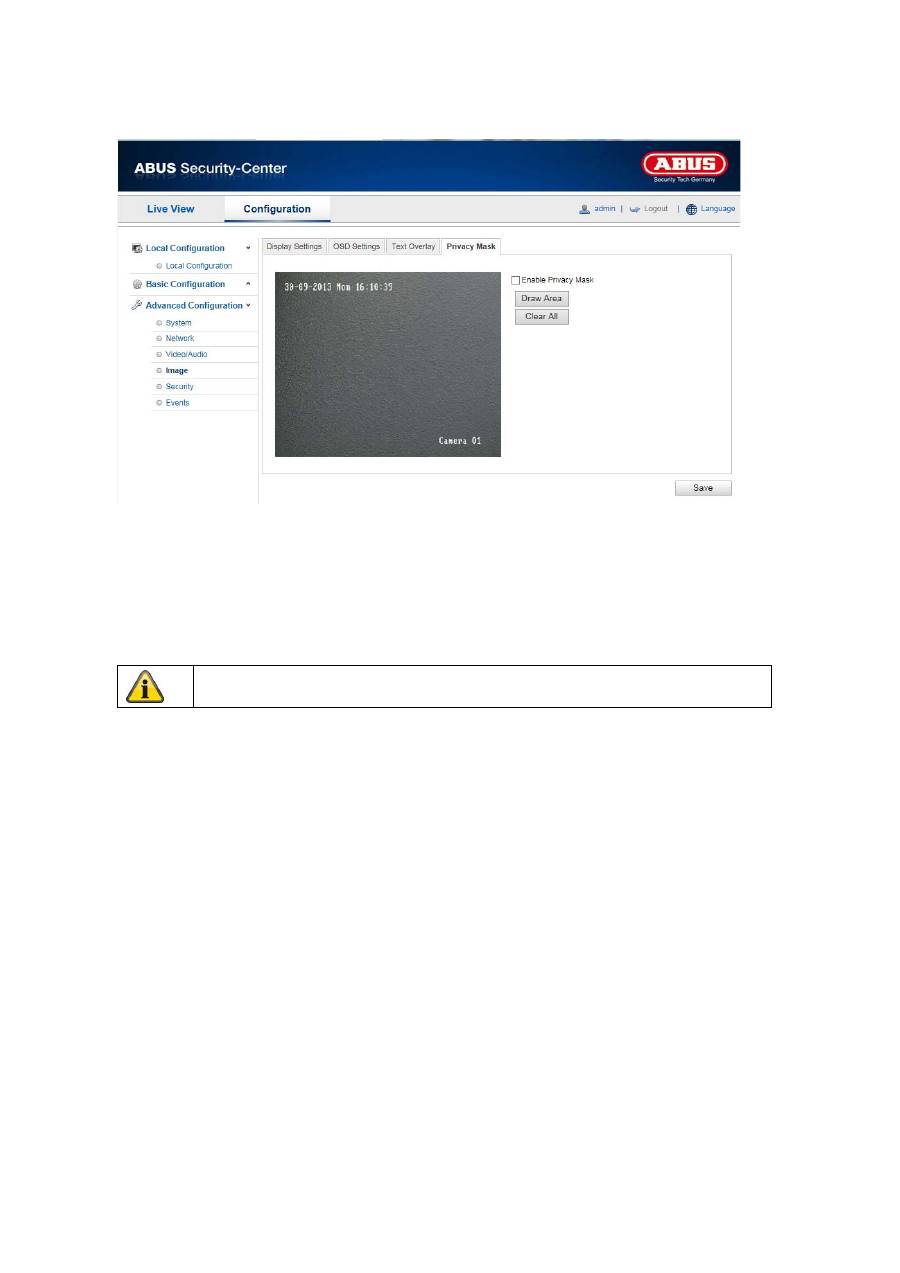
10.3.4.4 Privacy Mask
You can use privacy masks to hide certain areas in the live view to prevent that recording or viewing these
areas in the live view is possible. A maximum of 4 rectangular privacy masks can be set up on the video
image.
To set up a privacy mask, proceed as follows: Select “Enable Privacy Mask” checkbox. To add a privacy
mask, click “Draw Area”. You can now mark an area on the camera image using your mouse. You can
then mark 3 additional areas. By clicking on “Delete All”, you can delete all configured privacy masks.
Apply the settings made with “Save”.
97
10.3.6 Security
Menu item
Description
Available in mode
User
User administration
Basic Configuration,
Advanced
Configuration
RTSP
Authentication
Settings for the date and time formats
Advanced
Configuration
Anonymous
Visit
Access without user name and password
Advanced
Configuration
IP address
filter
Filtering IP addresses for access to controlling the
camera
Advanced
Configuration
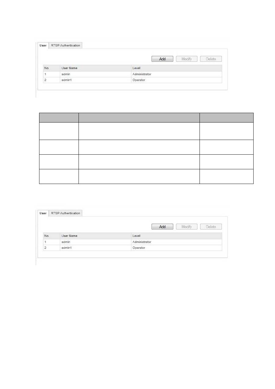
10.3.6.1 Security
With this menu item, you can add, edit or delete users.
To add a user or to edit one, click “Add” or “Modify”.
A new window with the data and authorisations appears.
User Name
Here you assign the user name that needs to be entered for access to the camera.
Level
Select an individual user type for the user ID.
You can choose between two predefined levels: “Operator” or “User”.
As an operator, the following remote functions are available to you: live view, PTZ control, manual
recording, playback, two-way audio, search / query operating status.

98
As a user, the following remote functions are available to you: playback, search / query operating status.
To add further functions, click the corresponding checkbox.
Password
Here you assign the password that the corresponding user needs to enter for access to the camera.
Confirm
Confirm the password by entering it once more.
Apply the settings made with “Save”.
Click on “Cancel” to discard the data.
99
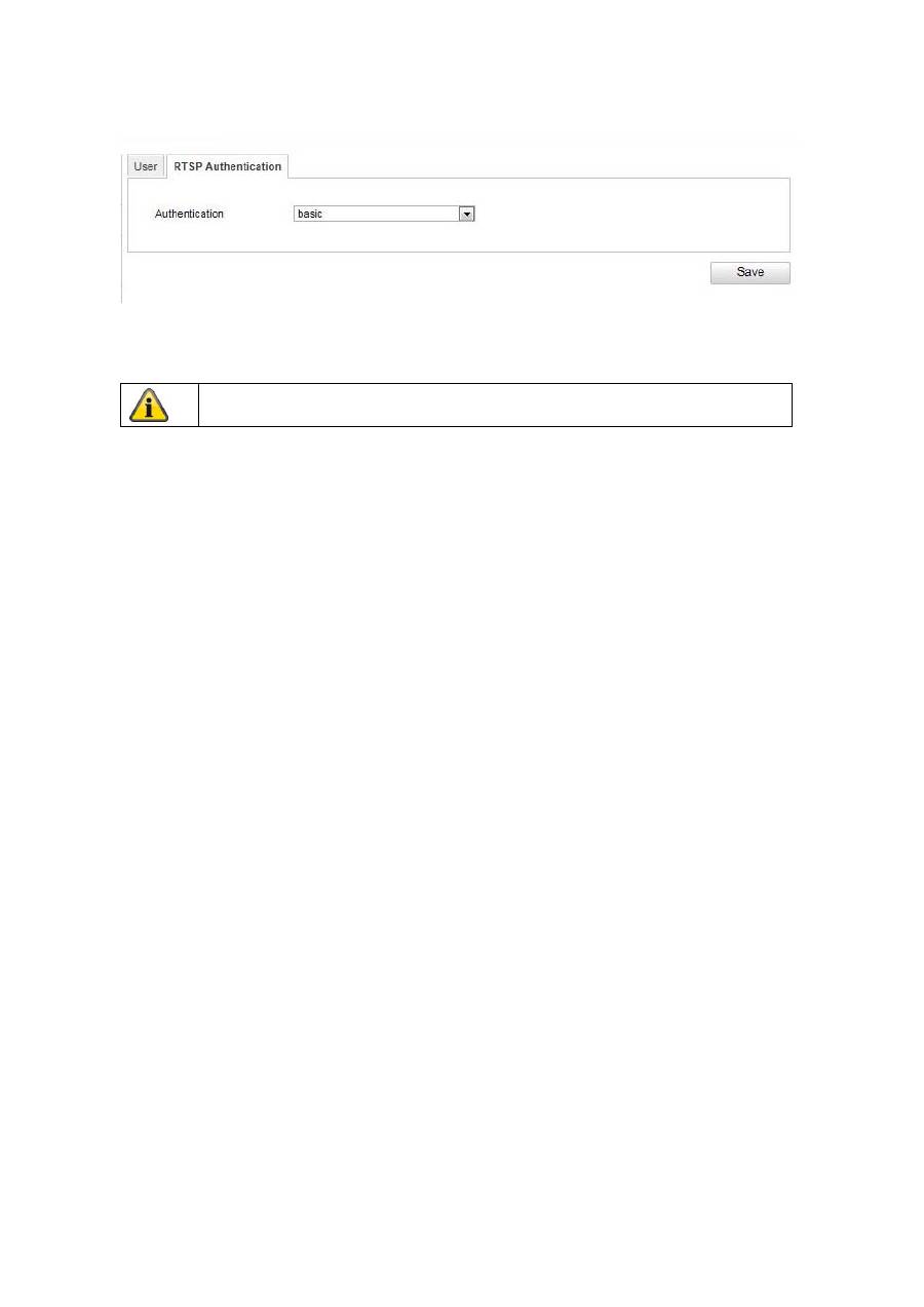
10.3.6.2 RTSP Authentication
You can secure the video stream of the live view.
Select “disable” to deactivate the function. To activate the function, select “basic”.
10.3.6.4 IP address filter
Activating the IP address filter
Ticking the selection box activates the filter function.
IP address filter type
Allowed: The IP addresses detailed further below can access the camera.
Forbidden: The IP addresses detailed further below are blocked. An IP can be entered following the
xxx.xxx.xxx.xxx format.
Apply the settings made with “Save”.
100
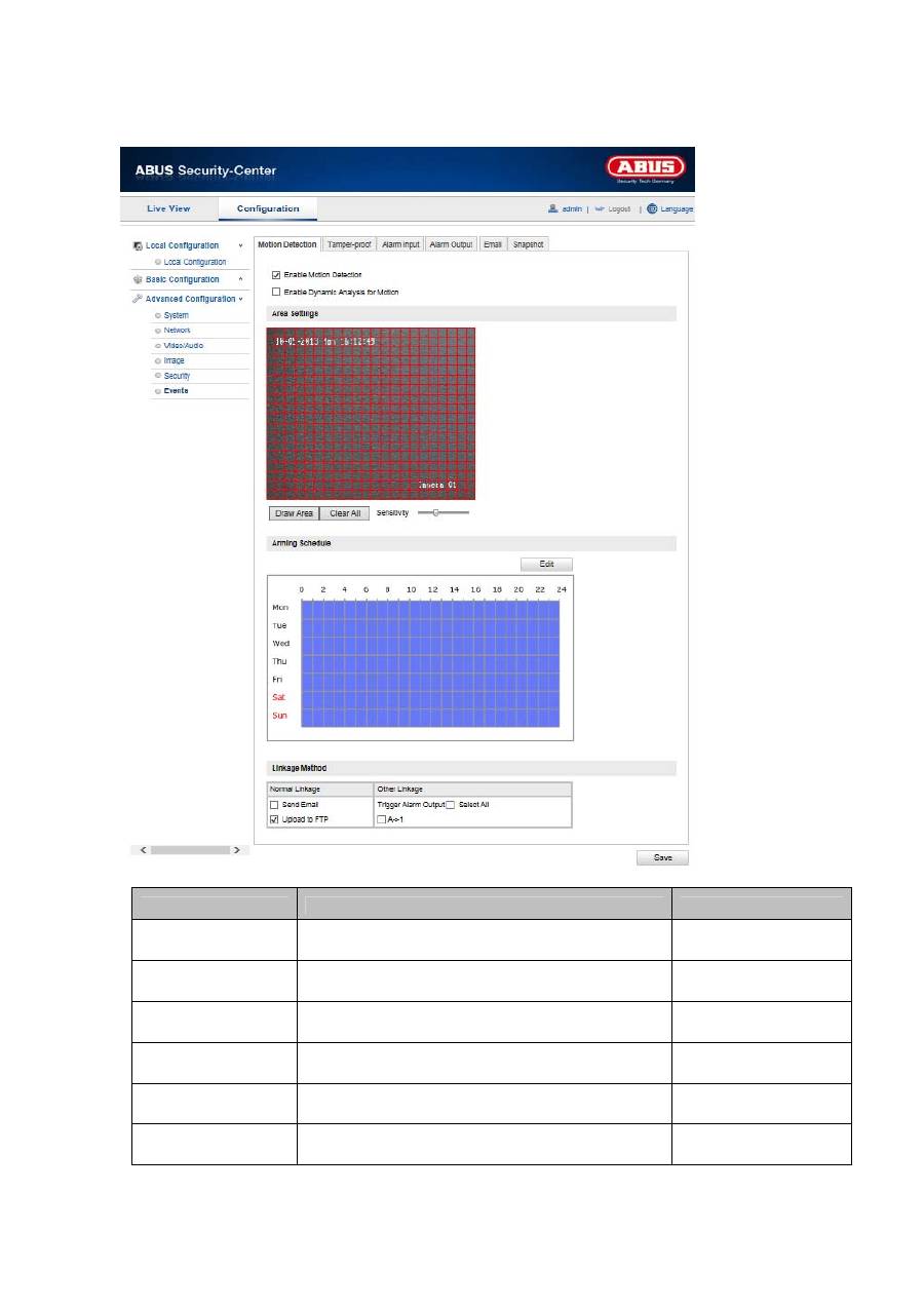
10.3.7 Events
Menu item
Description
Available in mode
Motion Detection
Settings for motion detection
Advanced
Configuration
Tamper-proof
Setting for the sabotage alarm
Advanced
Configuration
Alarm Input
Setting for the alarm input
Advanced
Configuration
Alarm Output
Setting for the alarm output
Advanced
Configuration
Setting for e-mail dispatch
Advanced
Configuration
Snapshot
Setting for the snapshot function
Advanced
Configuration
