Vaddio HE120 Operating Instructions: Parts and their functions
Parts and their functions: Vaddio HE120 Operating Instructions
Parts and their functions
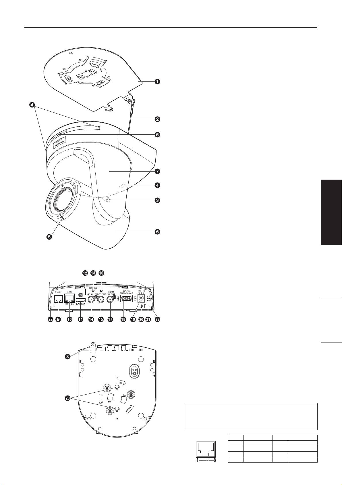
Camera unit
Mount bracket for installation surface
(supplied accessory)
Mount this bracket onto the installation surface, and then
attach the camera main unit to the bracket.
Drop-prevention wire
This wire is screwed down to the bottom panel of the
camera main unit. Loop the circle part of the wire around
the hook of the mount bracket.
Hole for securing the camera pedestal
This hole is provided in the bottom panel of the camera
pedestal.
Wireless remote control signal light-sensing
area
The light-sensing area is provided in three places, on the
front panel of the camera pedestal and at the top of the
rear panel.
Status display lamp
This lights in the following way depending on the status of
the unit.
Orange: When the standby status is established
Green: When the power is on
Red: When trouble has occurred in the unit
Green and blinks twice:
When a signal matched by the remote control
ID has been received from the wireless remote
Operating
Instructions
control (optional accessory) while the power is
on
Orange and blinks twice:
When a signal which is not matched by the
remote control ID has been received from the
wireless remote control (optional accessory)
while the power is on
<Rear panel>
Camera head
This rotates in the up and down direction.
Tilt head
This rotates in the right and left direction.
Tally lamp
This comes on or goes off in response to the control from
Parts and
the controller but only when “On” has been selected as the
tally lamp use setting.
their functions
<Bottom panel>
RS-422 connector [RS-422]
This RS-422 connector (RJ45) is connected when
exercising serial control over the unit from an external
device. Use a cable with the following specifications for the
connection to this connector.
The tally lamp can be lit by shorting the TALLY signal
(pin 2) with GND (pin 1).
Do not apply a voltage to the TALLY signal pin.
LAN cable* (category 5 or above, straight cable),
max. 1000 meters [3280 ft]
*: Use of an STP (shielded twisted pair) cable is
recommended.
Pin No. Signal name Pin No. Signal name
1 GND 5 TXD+
2 TALLY 6 RXD+
3 RXD– 7 —
4 TXD– 8 —
35
Parts and their functions
(continued)
LAN connector for IP control [LAN ACT/LINK]
Hole used to secure cable cover
This LAN connector (RJ45) is connected when exercising
Use the screw provided to secure the cable cover.
IP control over the unit from an external device.
Use a cable with the following specifications for the
connection to the LAN connector:
SDI OUT connector [HD/SD SDI OUT]
This is the SDI video signal output connector.
When connecting through a hub:
LAN cable* (category 5 or above, straight cable),
max. 100 meters [328 ft]
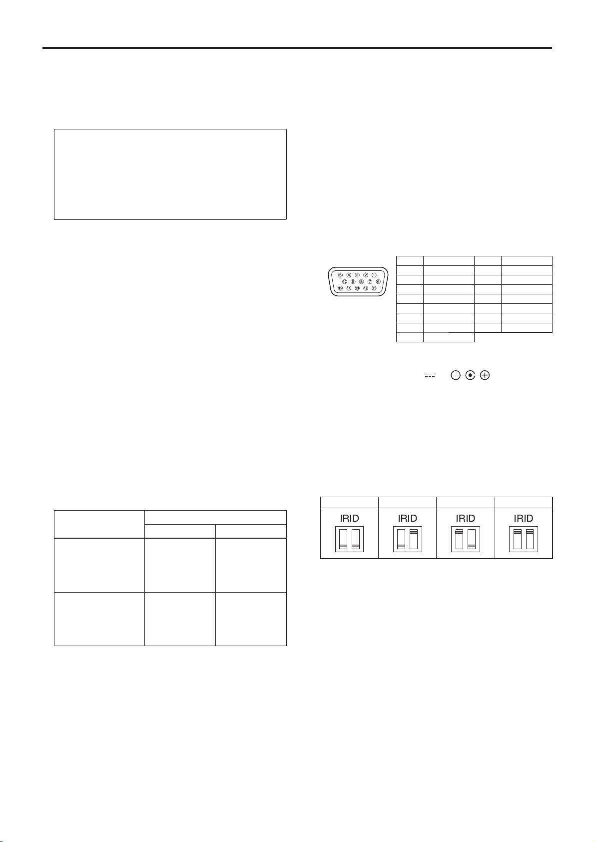
HD/SD analog output connector
When a hub is not used:
LAN cable* (category 5 or above, crossover cable),
[HD/SD ANALOG OUT]
max. 100 meters [328 ft]
This is the output connector of the camera’s HD/SD
component video signals.
*: Use of an STP (shielded twisted pair) cable is
recommended.
Provide a D-Sub 15-pin connecting cable (VGA cable)
or D-Sub 15-pin and BNC coaxial connector conversion
cable as the connecting table.
Use a high-quality cable.
HDMI connector [HDMI]
Pin No. Signal name Pin No. Signal name
This is the HDMI video output connector.
1 R/Pr 9 GND
2 G/Y 10 GND
3 B/Pb 11 GND
4 GND 12 GND
Anti-theft wire mounting hole
5 GND 13 —
The anti-theft wire bracket (available from a hardware
6 GND 14 —
store) is attached here.
7 GND 15 GND
8 GND
Service switch [SERVICE]
This switch is used for maintenance purposes: Do not
DC IN connector [12V IN ]
touch it.
Connect the AC adaptor supplied with the unit to this
If it is pressed by mistake, the service screen will be
connector to supply the DC 12 V voltage to the unit.
displayed. If this happens, turn off the power and then turn
it back on.
Cable clamp
This is used to hold the cable connection to the DC IN
G/L IN connector [G/L IN]
connector and prevent it from becoming disconnected.
This is the external sync signal input connector.
This unit supports BBS (Black Burst Sync) and tri-level
synchronization.
Supply to this connector the signals that correspond to the
IR ID switches [IR ID]
video signal format which has been set.
[CAM1] [CAM2] [CAM3] [CAM4]
External sync signal input format
Format
BBS Tri-level sync
1080/59.94p(i)
480/59.94i
1080/59.94i
1080/59.94i
480/59.94i
1080/59.94i
720/59.94p
—
720/59.94p
These are used to select the ID of the wireless remote
480/59.94p(i)
480/59.94i
—
control (optional accessory).
480/59.94i
480/59.94i
—
The IR ID switch settings “CAM1” to “CAM4” correspond
1080/50p(i)
576/50i
1080/50i
to the [CAM1] to [CAM4] buttons on the wireless remote
1080/50i
576/50i
1080/50i
control.
720/50p
—
720/50p
576/50p(i)
576/50i
—
576/50i
576/50i
—
Square holes (2) for cable cover tabs
The tabs on the two sides of the cable cover are fitted into
these holes.
VIDEO OUT connector [VIDEO OUT]
This is the output connector used for monitoring the
camera’s composite video signals. Use the monitor in the
Threaded hole (thread: 1/4-20UNC, ISO1222
internal synchronization mode.
[6.35 mm]) for mounting the camera
Provide a BNC coaxial cable as the connecting cable.
Use this hole when mounting the camera on a tripod, etc.
With the HD format, the signals are output with a 90H
delay from the HD signals.
36
Parts and their functions
(continued)
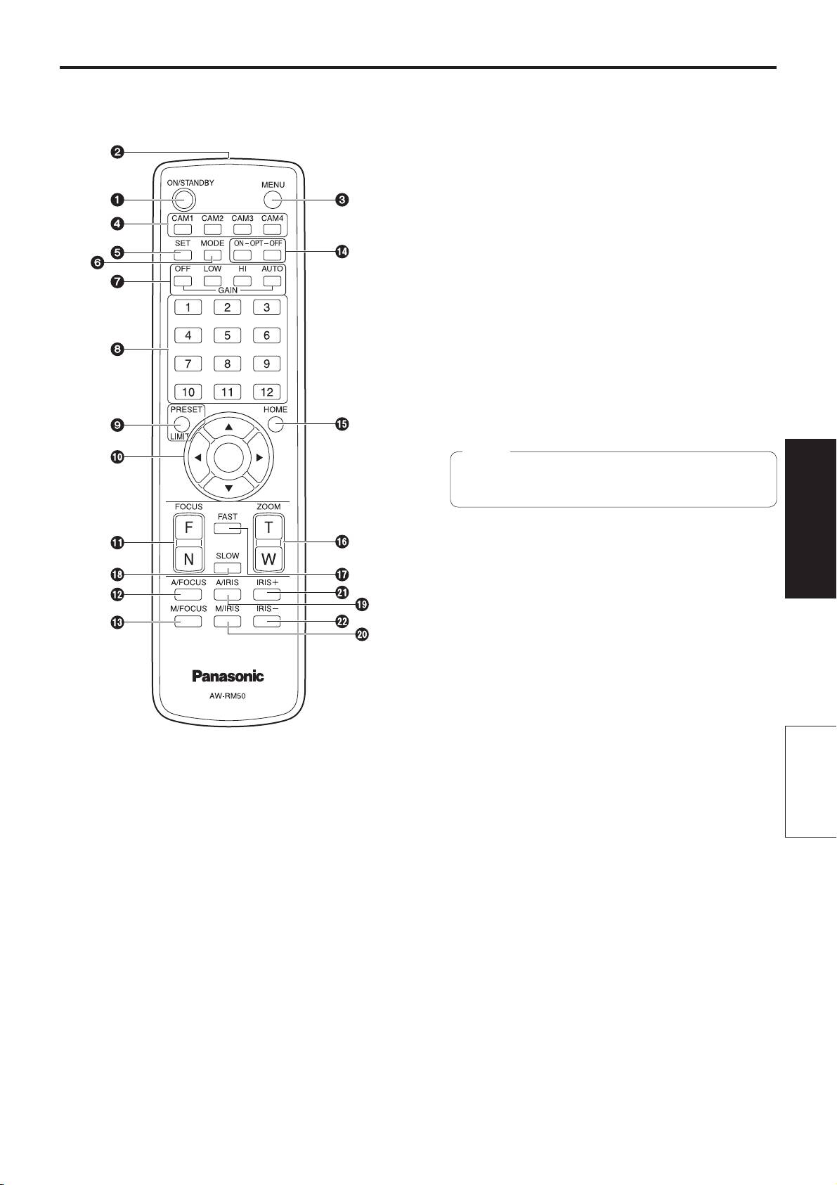
Wireless remote controller
CAM1 to CAM4 buttons
(optional accessory)
These are used to select the units that are to be operated.
Once a button has been selected, the unit corresponding
to the selected button can be operated.
SET button
If this button is held down for 2 seconds when the AWB A
memory or AWB B memory has been selected for the
white balance adjustment, the black balance and white
balance are adjusted automatically and registered in the
memory selected.
When this button is pressed for under 2 seconds, only the
white balance is adjusted automatically.
MODE button
This is used to select the video signals which are output
from the unit.
Each time it is pressed, the signals are switched between
the color bar signals and camera video signals.
Note
The setting for the Down CONV. Mode item when
color bars are displayed is fixed at “Squeeze”.
GAIN buttons [OFF] [LOW] [HI] [AUTO]
Operating
Instructions
These are used to set the gain.
The gain increase can be set in three steps using the
[OFF], [LOW] and [HI] buttons.
[LOW] is set to 9 dB, and [HI] is set to 18 dB.
When the [AUTO] button is pressed, the AGC function
is activated, and the gain is adjusted automatically
depending on the light quantity.
The maximum gain of the AGC function can be set using
the camera menu.
Preset memory call buttons [1] to [12]
These are used to call the information on the unit’s
ON/STANDBY button
directions and other settings, which have been registered
Each time this is pressed for 2 seconds, operation
in the unit’s preset memories No.1 to No.12, and
switches between turning on the unit’s power and
reproduce those settings.
establishing the standby status.
Parts and
Settings in preset memories No.13 and above cannot be
called from the wireless remote control.
their functions
Signal transmission window
PRESET/LIMIT button
This is used to register the settings in the preset
MENU button
memories or set or release the limiters.
Each time this is pressed for 2 seconds, operation
When a preset memory call button is pressed while the
switches between displaying the unit’s camera menu and
PRESET/LIMIT button is held down, the information on
exiting the camera menu.
the unit’s current direction and other settings is registered
When it is pressed quickly (for less than 2 seconds)
in the call button.
while a camera menu is displayed, the setting change is
Preset memory call buttons [1] to [12] correspond to the
canceled.
unit’s No.1 to No.12 preset memories.
Furthermore, the pan and tilt movement range limits
(limiters) are set and released by operating the MENU
button, PRESET/LIMIT button and the pan-tilt buttons
([], [], [] and []).
For details, refer to “Setting/releasing the limiters” (pages 87
to 88 in the <Operations and Settings>).
37

Parts and their functions
(continued)
Furthermore, the pan and tilt movement range limits
M/FOCUS button
(limiters) are set and released by operating the PRESET/
This is used when manually adjusting the lens focus.
LIMIT button, MENU button and the pan/tilt buttons ([],
The FOCUS buttons ([F] and [N]) are used when
[], [] and []).
performing the actual adjustment.
For details, refer to “Setting/releasing the limiters” (pages 87
to 88 in the <Operations and Settings>).
OPT buttons [ON] [OFF]
These are used for future expansion of the functions.
Pan-tilt buttons and menu operation buttons
They are not used at the present time.
[] [] [] [] []
(1) These are used to change the unit’s direction.
The unit is tilted in the up/down direction using the []
HOME button
and [] buttons and panned in the left/right direction
When this is pressed for 2 seconds, the unit’s direction
using the [] and [] buttons.
(panning or tilting) returns to the reference position.
The [] button does not work during tilting and
panning.
When the [] or [] and [] or [] buttons are
ZOOM buttons [T] [W]
pressed at the same time, the unit moves diagonally.
These are used to adjust the lens zoom.
The zoom is adjusted in the wide-angle using the [W]
(2) The buttons are used for menu operations when the
button and in the telephoto using the [T] button.
unit displays the camera menus.
Use the [], [], [] and [] buttons to select the
menu items.
FAST button
When a selected item has a sub-menu, the sub-menu
This is used to change the movement speed at which
will be displayed by pressing the [] button.
the panning, tilting, zooming and focusing operations are
When the cursor is aligned with a particular item and
performed to the high speed.
the [] button is pressed on the setting menu at the
bottom hierarchical level, the setting of the selected
item blinks.
Note
When the [] button is pressed after the setting
The operating speed for panning and tilting when
has been changed using the [], [], [] and []
the preset memory settings have been called can
buttons, the setting stops blinking, and the new setting
be changed using the Preset Speed item of the
is entered.
camera menu.
A setting for a regular menu item is reflected
immediately if it is changed while it is still flashing.
If the MENU button is pressed quickly (for less than
2 seconds) while the setting is in the blinking status,
SLOW button
the change will be canceled, and the setting selected
This is used to change the movement speed at which
prior to the change will be restored.
the panning, tilting, zooming and focusing operations are
performed to the low speed.
Notes
To prevent malfunctioning, there are a number of
menu items (Scene, Format, Down Conv. Mode
A/IRIS button
and Frequency) whose setting is not reflected
This establishes the setting for adjusting the lens iris
immediately even if it is changed while it is still
automatically in line with the light quantity.
flashing.
It is reflected only after the [] button has been
pressed, causing the setting to stop flashing and
M/IRIS button
the new setting to be entered.
This establishes the setting for adjusting the lens iris
A confirmation screen appears before the settings
manually.
of some menu items are to be entered.
The IRIS + and IRIS – buttons are used when performing
the actual adjustment.
FOCUS buttons [F] [N]
IRIS + button
These are used to adjust the lens focus manually when
This is used to adjust the lens iris in the opening direction.
the manual setting is established for the lens focus.
The focus is adjusted in the far using the [F] button and in
the near using the [N] button.
IRIS – button
This is used to adjust the lens iris in the closing direction.
A/FOCUS button
This is used when automatically adjusting the lens focus.
38
Оглавление
- Operating Instructions
- Contents
- Read this first!
- Installation precautions
- How to install and connect the unit
- Changing the direction of the nameplate
- Removing the camera
- Stand-alone installation (when the mount bracket is going to be used)
- Stand-alone installation (when the mount bracket is not going to be used)
- Connections
- Appearance
- Read this first! (For AW-HE120WP, AW-HE120KP)
- Read this first! (For AW-HE120WE, AW-HE120KE)
- Caution for AC Mains Lead
- Before use
- Characteristics
- Controller supported
- Operating precautions
- Concerning the wireless remote control (optional accessory)
- Parts and their functions
- Setting the remote control IDs
- Network settings
- Troubleshooting
- Specifications
- Index
