Televes DigiSlot DVB-T modulator, wall mount: Introduction
Introduction: Televes DigiSlot DVB-T modulator, wall mount
8
DVB-T modulator
Introduction
Product overview
The product is presented for two types of mounting: onto the wall (Ref. 554511),
and 19 inch cabinet mounting (Ref. 554611).
The modulator converts the HD A/V baseband signals into a DVB-T multiplex of
RF within the range 47 ~ 862 MHz.
It features 2 encoders and 1 additional RF input. The input signals of the
encoders can come from satellite receivers, CCTV cameras, Blu-ray players,
antennas, ... etc. Its output is a DVB-T TV multiplex which can be received with
the corresponding DTT STB.
The device can be used for monitoring, training courses and presentations,
schools, universities, hospitals, ..., in addition to being the best choice for public
premises which off er sporting events, VIP entertainment channels,.. and other.
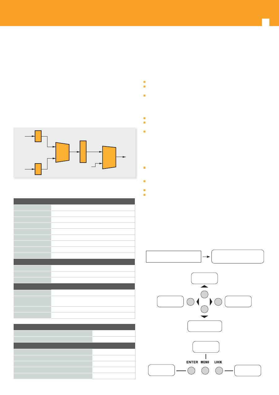
Blocks diagram
A/V in
Encoder
MUX
Modulator
Mix
RF in
RF out
A/V in
Encoder
Technical specifi cations Installation precautions
This section to explain the cautions the users must have to avoid any injures
when using or installing the product. For this reason, please read all details here
before installing or using the product.
General Precautions
Must be operated and maintained free of dust or dirty.
The cover should be securely fastened, do not open the cover of the products
with the power on.
After use, securely stow away all loose cables, external antenna, and others.
Power precautions
When you connect the power source, make sure it will not cause any overload.
Avoid operating on a wet fl oor in the open. Make sure the extension cable is
in good condition.
Make sure the power switch is off before you start to install the device.
Grounding Requirement
All function modules’ good grounding is the basis of reliability and stability of
devices. Also, they are the most important guarantee of lightning arresting and
interference rejection. Therefore, the system must follow this rule.
Grounding conductor must be a copper conductor in order to reduce high
frequency impedance, and the grounding wire must be as thick and short as
possible.
Users should make sure the both ends of grounding wire are electric
conductor and antirust.
It is prohibited to use any other device as part of grounding electric circuit.
The area of the conduction between grounding wire and device’s frame
should be no less than 2.5mm
2
Operation
Button introduction
LCD display window.
Display window for setting menu
Status display when power On.
DVB-T XXX.00MHz
X.XXMbps 0.0M
Setting value up
and moving up
To move left
To move right
Setting value down
and moving down
Back step
Confi rm setting
Lock button
DVB-T modulator section
Standard
EN300744
FFT mode
2K, 8K
Bandwidth
6M, 7M, 8M
Constellation
QPSK, 16QAM, 64QAM
Guard Interval
1/4, 1/8, 1/16, 1/32
FEC
1/2, 2/3, 3/4, 5/6, 7/8
MER
≥42dB
RF frequency
47~862MHz, 1KHz step
RF output level
-30~ -10dBm (81~97 dBμV), 0.1dB step
Interface
Front panel
buttons, LCD display
Remote manag.
Web NMS
Language
English
General
Mains
AC 100V~240V
Dimensions
360 x 280 x 50 mm (554511)
480 x 300 x 44 mm 1U rack 19” ( 554611)
Weight
2.6 kgs
Operating temp.
0~45 ºC
Confi gurations
LCN confi g
Yes
NIT Table confi g
Yes
Settings
Network Name
Yes
Network ID
Yes
Transport Stream ID (TSID)
Yes
Original Network ID (ONID)
Yes
Hierarchy Information
Yes
9
EN
DVB-T modulator
Initial Status
Switch On, then below status will be displayed, few seconds’ initialization then
open startup picture
Start up ...
Start OK ...
DVB-T XXX.00MHz
X.XXMbps Y.YYMbps
DVB-T: indicate the modulation standard of this device
XXX.XX MHz: indicate the output frequency, and the frequency range is
47~862MHz
X.XX Mbps: indicate the encoding bit rate in slot 1
Y.YY Mbps: indicate the encoding bit rate in slot 2
General setting for Main Menu
By pressing “Lock” key to enter the main menu, the LCD will display the
following pages:
1 Alarm Status
2 Encode Setting
3 Modulate Setting
4 IP Output Setting
5 Network Setting
6 Saving Config
7 Loading Config
8 Version
User pressing
UP
or
DOWN
buttons to specifi ed menu item, and then pressing
ENTER
to enter the submenus as below:
1)
Alarm status
--- the alarm indicator will light on if there is no A/V signals
input.
2)
Encoder setting
--- choose this submenu, the LCD will show “input setting”,
press the
ENTER
key and control the
UP
or
Down
key to move the arrow.
User could fi nd how to set the audio and video encoding bit rate.
3)
Modulator setting
When the “modulator setting” submenu has been chosen, users can fi nd below
diff erent parameters for setting. And the LCD window would respectively show
like these.
3.1 Bandwidth
3.2 Constellation
3.3 Transmisson Mod
3.4 Guard Interval
3.5 Code Rate
3.6 RF Frequency
3.7 RF Outlevel
3.1-
Bandwidth
There are three possible options provided for selecting bandwidth: 6M, 7M, and
8M. When the display shows them, user just need swift
LEFT
and
RIGHT
key to
choose and repressing “
ENTER
” for confi rm.
3.2-
Constellation
Three diff erent constellations: QPSK, 16QAM, and 64QAM will be show on the
LCD window when Constellation been entered.
- QPSK: Quadrature Phase Shift Keying, Selecting this option indicates the
device works as DVB-S modulation mode
- 16QAM: Quadrature Amplitude Modulation is 16
- 64QAM: Quadrature Amplitude Modulation is 64
Setting method just the same, when the display shows them, user just need
swift
LEFT
and
RIGHT
key to choose and repressing “
ENTER
” for confi rm.
3.3-
Transmission mode
After entering Trans mode, the LCD would show the current working mode.
User can move
LEFT/RIGHT
key and repress
ENTER
key to select and confi rm.
2K and 8K are the options.
- 2K: when the device works as current mode, the number of current carrier
is 2048.
- 8K: when the device works as current mode, the number of current carrier
is 8192.
3.4-
Guard interval
In communications, guard intervals are used to ensure that distinct transmissions
do not interfere with one another. These transmissions may belong to diff erent
operators (as in TDMA) or same operator (as in OFDM).
The purpose of the guard interval is to introduce immunity to propagation
delays, echoes and refl ections, to which digital data is normally very sensitive.
There are four possible options provided to be selected. They are 1/4, 1/8, 1/16,
1/32. User can shift the
LEFT/RIGHT
key to select and press
ENTER
to confi rm.
3.5-
FEC
Forward Error Correction (FEC) rates include 1/2, 2/3, 3/4, 5/6, and 7/8. After
entering FEC submenu, and the LCD display would shows them, users just need
press
LEFT
and
RIGHT
button to choose, and press
ENTER
button for confi rm.
3.6-
RF Frequency
The RF output frequency range is from 30 to 1000MHz with 1K stepping. After
entering the RF frequency setting submenu, users the can press
LEFT
,
RIGHT
,
UP
, and
DOWN
buttons to adjust the frequency and confi rm by press
ENTER
button.
3.7-
RF out level
The RF attenuation range is from -30~-10dBm (81~97dBμV) with 0.1dB step.
After entering this setting submenu, user can shift
UP/DOWN/LEFT/RIGHT
key
to set the output level and press
ENTER
to confi rm.
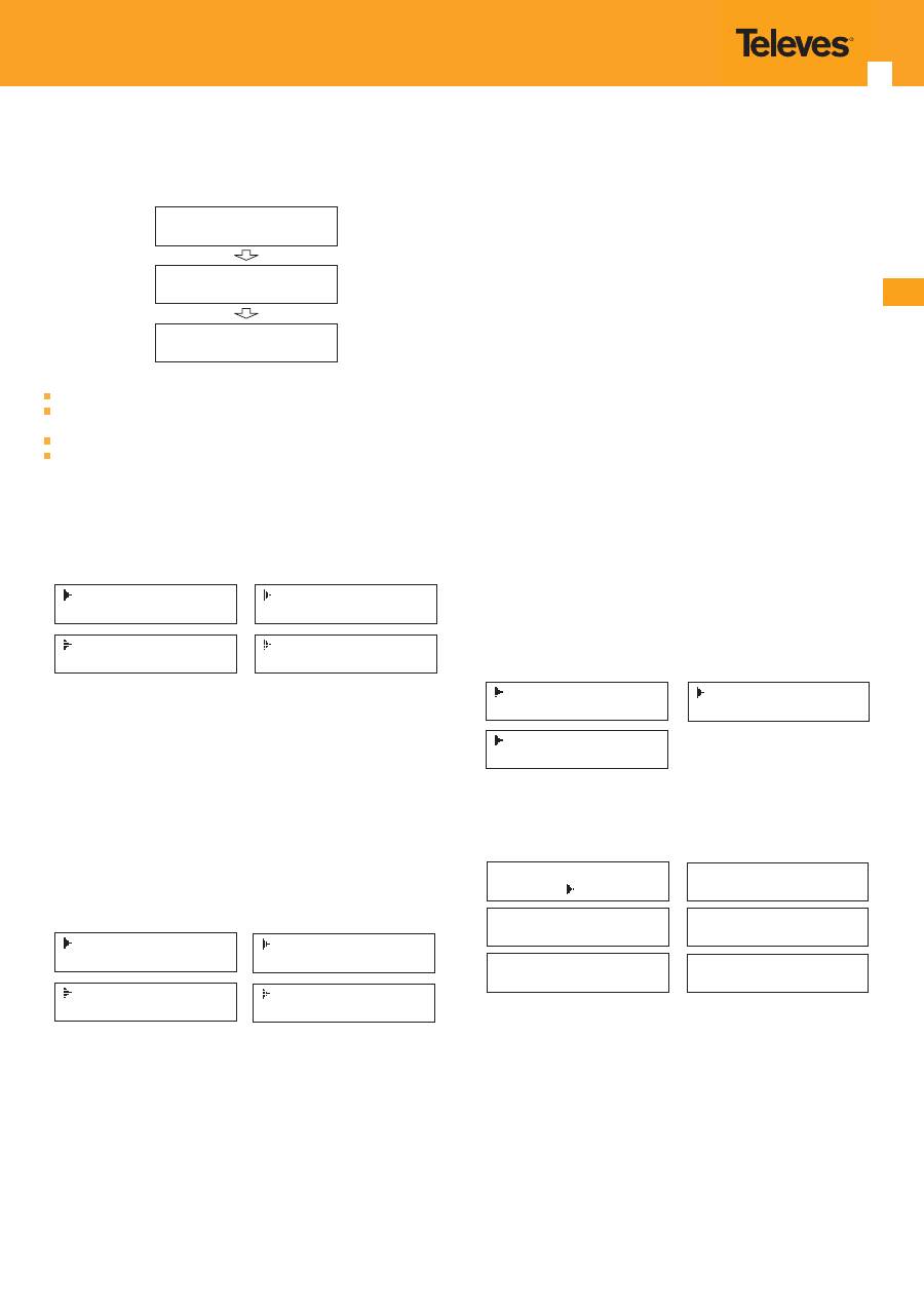
4)
IP Output Setting
4.1 IP Output
4.2 Service IP
4.3 Output IP
4.4 Subnet Mask
4.5 Gateway
4.6 Port
User can press “
UP/DOWN
” to choose this item. “
Enter
” and “
LEFT/RIGHT
” to
set the parameters.
If not set the following parameters will be no use, the IP Output will not work.
IP Output
OFF ON
Service IP
192.168.002.137
Output IP
224.002.002.002
Subnet Mask
255.255.255.000
Gateway
192.168.002.000
Port
01234
4.1-
IP Output
The IP Output option, must be enable.
4.2-
Service IP
The IP Output Port address. The format is xxx.xxx.xxx.xxx (like as 192.168.2.137).
4.3-
Output IP
The IP Output data receive address. The format is xxx.xxx.xxx.xxx (like as
224.2.2.2). After set the Output IP address , you must use the new address to
receive IP Output data.
4.4-
Subnet Mask
General is 255.255.255.0, it is must the same in a local area network.
4.5-
Gateway
If the device is in diff erent net segment, you must set the gateway.
