Jotul I570: 3.0 Installation
3.0 Installation: Jotul I570
34
3.0 Installation
3.1 Floor
Foundation
You need to make sure the foundation is suitable for a fireplace.
See
“2.0 Technical Data”
for specified weight.
Requirements for protection of wooden
flooring beneath the fireplace
The Jøtul I
570
has a heat shield underneath to protect the floor
from radiated heat. The product can therefore be positioned
directly on a wooden floor that is covered by a sheet of metal or
other non-inflammable material. The recommended minimum
thickness is
0.9 mm
. The plate must cover the entire floor surface
within the surround.
We recommend the removal of any flooring that is not attached
to the foundation (“floating floors”) beneath the installation.
Any floor covering of inflammable material, such as linoleum,
carpets, etc. must be removed from under the floor plate.
Requirements for protection of inflammable
floors in front of the fireplace
The floor in front of the fireplace must be protected by a sheet
of metal or other non-inflammable material. The recommended
minimum thickness is 0.9 mm. The floor plate must comply with
national laws and regulations.
Contact your local building authorities regarding restrictions and
installation requirements.
3.2 Wall
Distance to inflammable wall protected by
insulation (Fig. 1)
Insulation requirements
• 100 mm firewall + 50 mm rock wool, or
• 50 mm calsium silicate + 50 mm rock wool 120 kg/m
3
with
aluminium foil on one side, or
• 2 x 50 mm calsium silicate firewall plates.
Distance to inflammable wall protected by
firewall (Fig. 1)
Requirements for regulation firewalls
The firewall must be at least 100 mm thick and made of brick,
concrete or lightweight concrete + 50 mm insulation. Other
materials and structures with satisfactory documentation may
also be used.
Contact your local building authorities regarding restrictions and
installation requirements.
Distance to non-inflammable wall (Fig. 1)
“Non-inflammable wall” here means a non-bearing wall of
continuous brickwork/concrete.
Requirements for fireplace surround
Fireplace surrounds must be made of a non-inflammable material
Note that the entire back wall and, if any, side walls within the
surround must be covered with insulation/firewalls.
If the cowl is built up to the ceiling and the ceiling is of
inflammable material, extra panelling must be installed above
the top of the heating chamber and above the cowl’s vents in
order to prevent the ceiling becoming hot. Use for example:
Rock wool,
100 mm
thick, on a steel plate
(min. 0.9 mm)
. Ensure
there is adequate ventilation in the top of the cowl – e.g. a gap
under the ceiling.
NB: Remember that it must be possible to sweep and inspect
the installation.
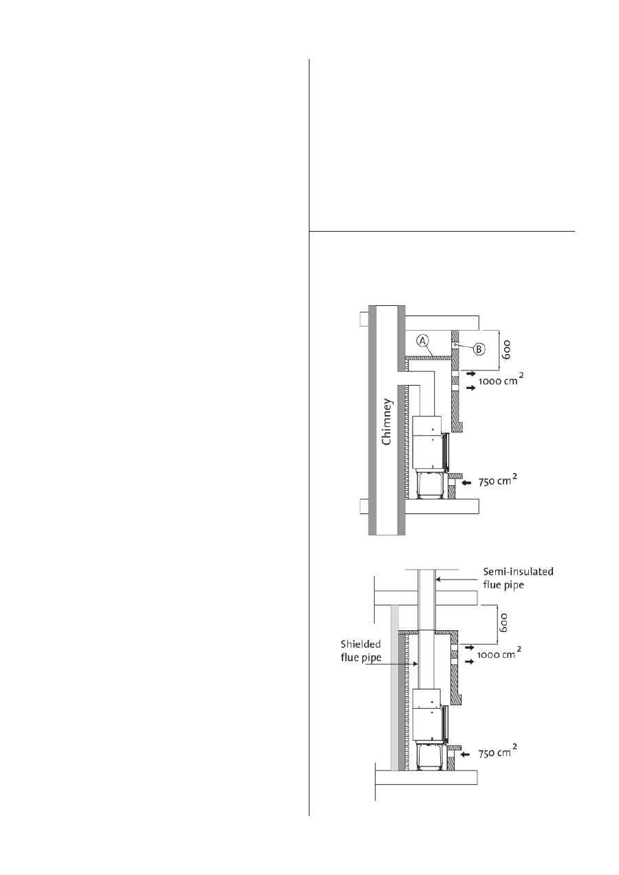
3.3 Air supply (Fig. 2)
Fig. 2
ENGLISH
35
ENGLISH
Air must flow between the insert and the brickwork, and it is
extremely important that there is an unimpeded air supply to
the air inlets.
The air inlet dimensions specified in the text are minimum
requirements.
Required air vent sizes (for air circulation):
Base: Minimum of 750 cm
2
free opening.
Top: Minimum of 1000 cm
2
free opening.
This is a safety measure to ensure that the build-up of heat inside
the surround does not become too great and that the output of
heat to the room is adequate.
If the house is poorly ventilated, the room must be fitted with an
additional supply of outside air, e.g. by means of a separate duct
under the fireplace. The outside air duct should be as straight
as possible and must be made of a non-inflammable material.
It must be possible to close the ducts with a damper in order to
keep out cold air when the stove is not being used.
3.4 Ceiling
The fireplace can be fitted with the top edge of the hot air
opening of the surround
at least 600 mm
below a ceiling of
inflammable material. Ensure there is adequate ventilation in
the top of the cowl – e.g. a gap under the ceiling.
3.5 Chimney and flue pipe
• The fireplace must only be connected to a chimney and
flue pipe approved for solid fuel fireplaces with flue gas
temperatures as specified in
«2.0 Technical Data»
.
•
The cross-section of the chimney must be designed to fit the
fireplace. Use
«2.0 Technical Data»
to calculate the correct
chimney cross-section.
• The chimney must be connected in accordance with the
installation instructions of the chimney supplier.
• Before a hole is made in the chimney, the product should be
test-mounted in order to correctly mark the position of the
fireplace and the hole in the chimney. See
Fig. 1
for minimum
dimensions.
• Make sure that the flue pipe rises all the way up to the
chimney.
• With a rear outlet, use a flue pipe bend with a sweep hatch
to allow sweeping.
•
Please note that it is extremely important for connections to
have a degree of flexibility. This is to prevent any movement
in the installation leading to the formation of cracks.
•
For recommended chimney draught, see
«2.0 Technical Data»
.
For flue pipe dimensions with the relevant cross-section, see
“2.0 Technical Data”
.
NB! The minimum recommended chimney length is 3.5 m from
the flue pipe insert. If the draught is too strong, a flue pipe
damper can be installed and used to reduce the draught.
Weight must not be transferred from the fireplace structure to the
chimney. The fireplace structure must not hinder the chimney’s
ability to move, and must not be anchored to the chimney.
3.6 Preparation/installation
NB: Check that the fireplace is undamaged before installation
begins. The product is heavy! Ensure you have help when
positioning and installing it.
After unpacking the insert take out the box with contents. To
make the product lighter, remove the door.
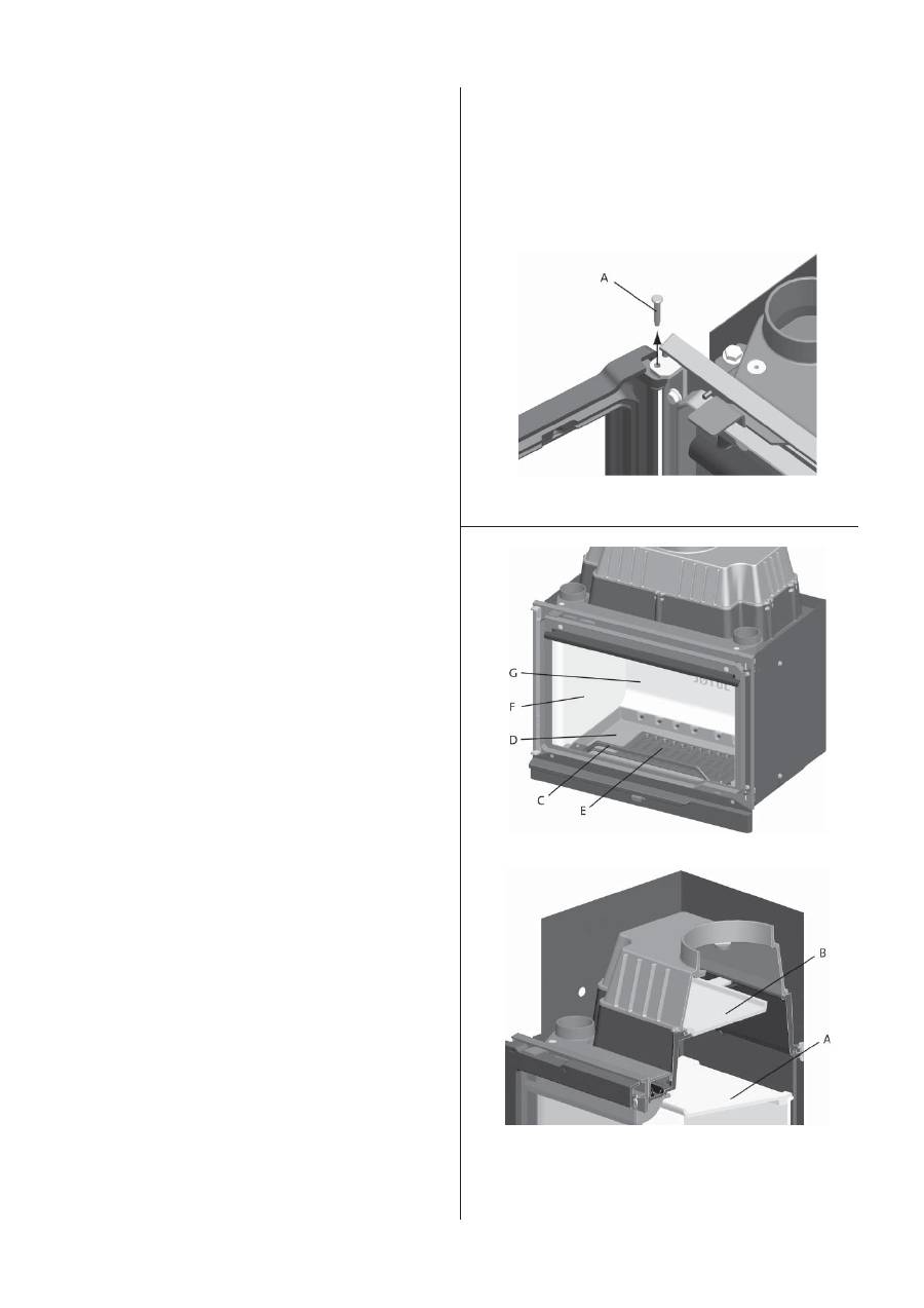
Fig. 3 A
1. Open
the
door.
2. Tap out the hinge pins and pull out the door.
Fig. 3 B
Fig. 3 C
3. To make the installation easier, remove the burn plates
(fig.
3 B-G/F)
, baffle plate
(fig. 3 c-A)
, exhaust deflector
(fig. 3 C-B)
,
log retainer
(fig. 3 B-C)
, inner bottom
(fig. 3 B-D)
, and grate
(fig. 3 B-E)
. See section
“4.1 Replacing the burn plates, baffle
plate and exhaust deflector”.
36
Attaching the legs and securing the base
heat shield
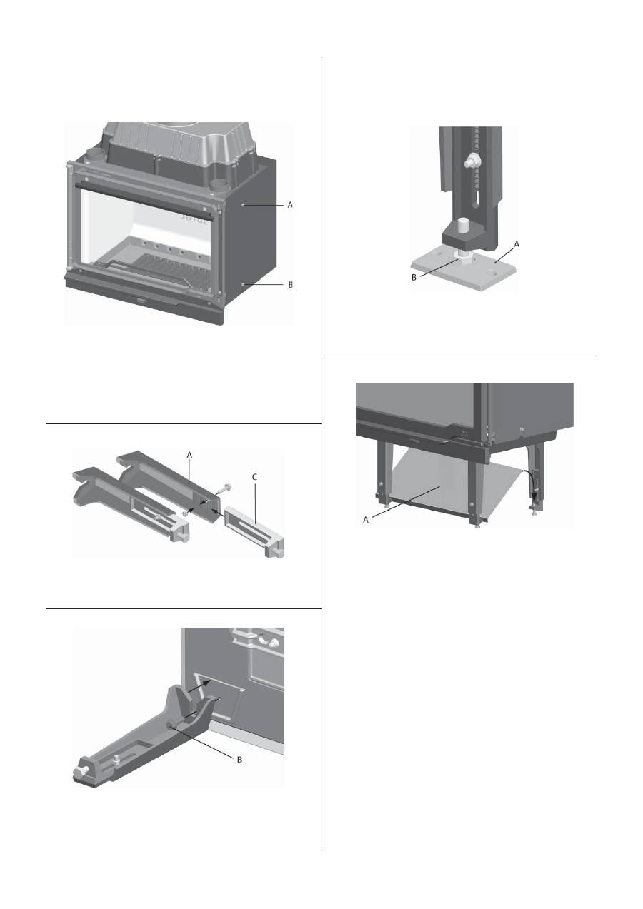
Fig. 4
4. Dismount the insert’s heat shield by unscrewing the upper
screw on both sides of the insert
(fig. 4 A)
. Loosen the lower
screws
(fig. 4 E)
somewhat and pull the heat shield upwards
and then remove it.
5. Lay the insert carefully down on its back (you can protect the
floor with the wooden pallet and cardboard packaging).
Fig. 5
6. Assemble the 4 legs
(fig. 5 A)
with the 4 adjustable joints
(fig.
5 C)
using the 4 screws and nuts that are in a bag in the box.
Fig. 6
7. Then attach these to the insert using the four
(B)
M6 x 25
mm countersunk screws
(B)
and washers. The screws and
washers are already attached to the base of the insert. Turn
the adjustable joints to obtain the required height.
8. Stand the burn chamber up.
9. Make final adjustments to the legs once the insert has been
test-mounted.
Fig. 7
10. The bracket
(fig. 7 A)
should be placed under the screw heads
to protect the surface and to prevent the insert from slipping
out of place. Make final adjustments using the M10 x 45 mm
screws
(fig. 7 B)
attached to the joints.
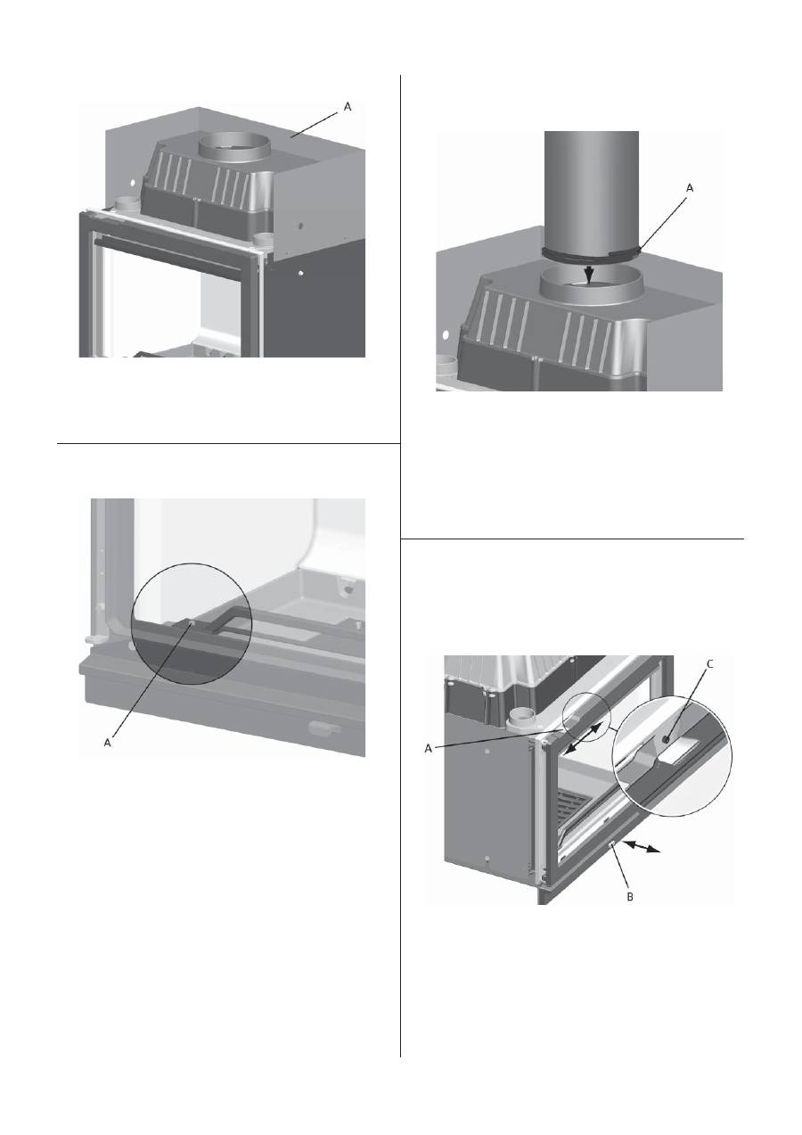
Fig. 8
11. Position the heat shield on the insert’s adjustable joints
(fig. 8 A)
.
12. Refit all the parts that were removed for easier handling of
the insert.
13. Reposition the previously removed heat shield
(see step 4)
.
ENGLISH
37
ENGLISH
Fig. 11
4. Secure the flue pipe in the insert’s smoke outlet using gasket
rope.
NB: It is important that the joints are completely sealed. Air
leakage may cause malfunction.
3.8 Checking the functions
Check the control handles once the insert is in place. These should
move easily and work in a satisfactory manner.
Fig. 12
Air vent (fig. 12 - A)
Left position = closed
Right position = open
NB! Before use, open the door and remove the screw (fig. 12 C).
Ignition vent (fig. 12 - B)
Pulled out
= open
Pushed in
= closed
Fig. 9
14. Unscrew the upper heat shield at the rear
(fig. 9 A)
. Turn it
upside down and screw it firmly in position using the same
screws it was fastened with before.
Fig. 10
Log retainer
Mount the log retainer onto the knobs
(fig. 10 A)
on the rear of
the front frame.
3.7 Assembly/installation
Installation to the chimney
1. Test-mount the insert first without making a hole in the
chimney. See
fig. 1
for distances to firewall.
2. The insert is to be installed with a Ø200 mm flue pipe of
approved thickness.
3. Place the insert into its final position.
Оглавление
- 1.0 Forhold til myndighetene
- 3.0 Installasjon
- 4.0 Service
- 1.0 Forhold til myndighederne
- 3.0 Installation
- 4.0 Service
- 1.0 Kontroll och lagstiftning
- 3.0 Installation
- 4.0 Service
- 1.0 Viranomaisvaatimukset
- 3.0 Asennus
- 4.0 Huolto
- 1.0 Regulatory information
- 3.0 Installation
- 4.0 Servicing
- 1.0 Informations réglementaires
- 3.0 Installation
- 4.0 Entretien
- 1.0 Información normativa
- 3.0 Instalación
- 4.0 Mantenimiento
- 1.0 Informazioni sulle normative
- 3.0 Installazione
- 4.0 Manutenzione
- 1.0 Zgodność z przepisami
- 3.0 Montaż
- 4.0 Obsługa
- 1.0 Нормативная база
- 3.0 Установка
- 4.0 Текущий ремонот
- 1.0 Obecné informace
- 3.0 Montáž
- 4.0 Opravy
