ABUS TVIP52502 Operating instructions – страница 4
Инструкция к ABUS TVIP52502 Operating instructions
Оглавление
- Инструкция по эксплуатации
61
Icon explanation
A flash in the triangle is used if there is danger for the health, e.g. by an electric shock.
An exclamation mark in the triangle points to an important note in this user manual
which must be minded.
This symbol can be found when you are to be given tips and information on operation.
Important safety advice
The warranty will expire for damage due to non-compliance with these operating
instructions. ABUS will not be liable for any consequential loss!
ABUS will not accept liability for damage to property or personal injury caused by
incorrect handling or non-compliance with the safety-instructions.
In such cases the warranty will expire.
The following safety information and hazard notes are not only intended to protect your health, but
also to protect the device from damage. Please read the following points carefully:
There are no components inside the product that require servicing. Dismantling the product
invalidates the CE certification and the guarantee / warranty.
The product may be damaged if it is dropped, even from a low height.
Install the device so that the image sensor is not subjected to direct sunlight. Pay attention to the
installation instructions in the corresponding section of this user guide.
This device is designed solely for use indoors or in weatherproof housing.
Avoid the following adverse conditions during operation:
Moisture or excess humidity
Extreme heat or cold
Direct
sunlight
Dust or flammable gases, vapours, or solvents
Strong
vibrations
Strong magnetic fields (e.g. next to machines or loudspeakers)
The camera must not be installed on unstable surfaces
General safety information:
Do not leave packaging material lying around. Plastic bags, sheeting, polystyrene packaging, etc.,
can pose a danger to children if played with.
The surveillance camera contains small parts which could be swallowed, and should be kept out of
reach of children for safety reasons.
Do not insert any objects into the device through the openings.
Only use replacement devices and accessories that are approved by the manufacturer. Do not
connect any non-compatible products.
Please pay attention to the safety information and user guides for the other connected devices.
Check the device for damage before commissioning. Do not put the device into operation if you
detect any damage.
Adhere to the operating voltage limits specified in the technical data. Higher voltages could
destroy the device and pose a health risk (electric shock).
62
Safety information
1. Power supply: power supply unit 100-240 V AC, 50/60 Hz
/
12 VDC, 1 A (included in the scope of
delivery)
Only operate this device on a power source which supplies the power specified on the type plate. If
you are unsure which voltage is supplied at the installation location, contact your power supply
company. Disconnect the device from the power supply before carrying out maintenance or
installation work.
2. Overloading
Avoid overloading electrical sockets, extension cables, and adapters, as this can result in fires or
electric shocks.
3. Cleaning
Only use a damp cloth to clean the device. Do not use corrosive cleaning materials.
Disconnect the device from the power supply while doing so.
Warnings
Observe all safety and operating instructions before putting the device into operation for the first time.
1. Observe the following information to avoid damage to the power cable and plug:
Do not modify or manipulate the power cable or plug.
Do not bend or twist the power cable.
Do not pull the cable when disconnecting the device from the power – always take hold of the
plug.
Ensure that the power cable is positioned as far away as possible from any heating
equipment, as this could otherwise melt the plastic coating.
2. Follow these instructions. Non-compliance with these instructions could lead to an electric shock.
Never open the housing or power supply unit.
Do not insert any metallic or flammable objects into the device.
Use overvoltage protection to prevent damage caused by overvoltage (e.g. electrical storms).
3. Disconnect defective devices from the power immediately and contact your specialist dealer.
During the installation into an existing video surveillance system make sure that all devices
are disconnected from the low and supply voltage circuit.
If in doubt allow a professional electrician to mount, install and wire-up your device. Improper
electrical connection to the mains does not only represent at threat to you but also to other
persons.
Wire-up the entire system making sure that the mains and low voltage circuit remain
separated and cannot come into contact with each other in normal use or due to any
malfunctioning.
Unpacking
While you are unpacking the device please handle it with utmost care.
If you notice any damage of the original packaging, please check at first the device.
If the device shows damages, please contact your local dealer.

63
Table of contents
1. Intended
use
.......................................................................................................................... 65
2. Scope of delivery .................................................................................................................... 65
3. Features and functions ........................................................................................................... 65
4. Device
description
.................................................................................................................. 65
5. Description of the connections ............................................................................................... 66
6. Inital
start-up
.......................................................................................................................... 67
7. Accessing the network camera for the first time .................................................................... 67
8. Password
prompt
................................................................................................................... 69
9. User
functions
........................................................................................................................ 70
9.1 Menu bar .................................................................................................................................. 70
9.2 Live image display ................................................................................................................... 71
9.3 Audio / video control ................................................................................................................ 71
10. Configuration
.......................................................................................................................... 72
10.1 Local configuration ................................................................................................................. 72
10.2 Basic configuration ................................................................................................................. 74
10.3 Advanced Configuration ......................................................................................................... 75
10.3.1 System ................................................................................................................................ 75
10.3.1.1 Device Information ........................................................................................................... 76
10.3.1.2 Time Settings ................................................................................................................... 77
10.3.1.3 Maintenance .................................................................................................................... 78
10.3.1.4 DST .................................................................................................................................. 79
10.3.2 Network ............................................................................................................................... 80
10.3.2.1 TCP/IP ............................................................................................................................. 81
10.3.2.2 Port .................................................................................................................................. 82
10.3.2.3 DDNS ............................................................................................................................... 83
10.3.2.4 FTP .................................................................................................................................. 86
10.3.2.5 UPnP™ ............................................................................................................................ 87
10.3.3 Video / Audio ....................................................................................................................... 88
10.3.3.1 Video ................................................................................................................................ 89
10.3.3.2 Audio ................................................................................................................................ 90
11.3.4 Image .................................................................................................................................. 91
10.3.4.1 Display Settings ............................................................................................................... 92
10.3.4.2 OSD Settings ................................................................................................................... 94
10.3.4.3 Text Overlay ..................................................................................................................... 95
10.3.4.4 Privacy Mask .................................................................................................................... 96
10.3.6 Security ............................................................................................................................... 97

64
10.3.6.1 Security ............................................................................................................................ 97
10.3.6.2 RTSP Authentication ........................................................................................................ 99
10.3.6.4 IP address filter ................................................................................................................ 99
10.3.7 Events ............................................................................................................................... 100
10.3.7.1 Motion Detection ............................................................................................................ 101
10.3.7.2 Tamper-proof ................................................................................................................. 103
10.3.7.3 Alarm Input ..................................................................................................................... 105
10.3.7.4 Alarm Output .................................................................................................................. 107
10.3.7.5 Email .............................................................................................................................. 109
10.3.7.6 Snapshot ........................................................................................................................ 111
11. Maintenance and cleaning ................................................................................................... 112
11.1 Maintenance ........................................................................................................................ 112
11.2 Cleaning ............................................................................................................................... 112
12. Disposal ............................................................................................................................... 113
13. Technical Data
..................................................................................................................... 113
14. GPL license information ....................................................................................................... 114
65
1. Intended use
The PTZ network dome camera provides discreet, powerful surveillance. High-resolution images, control
options, a high-quality zoom lens, and alarm functions ensure efficient monitoring. The moving 24-hour
watchman sets standards: Easily integrated into existing IP networks, it combines the optical precision of a
Speed Dome camera with the flexibility and readiness for the future of a network camera.
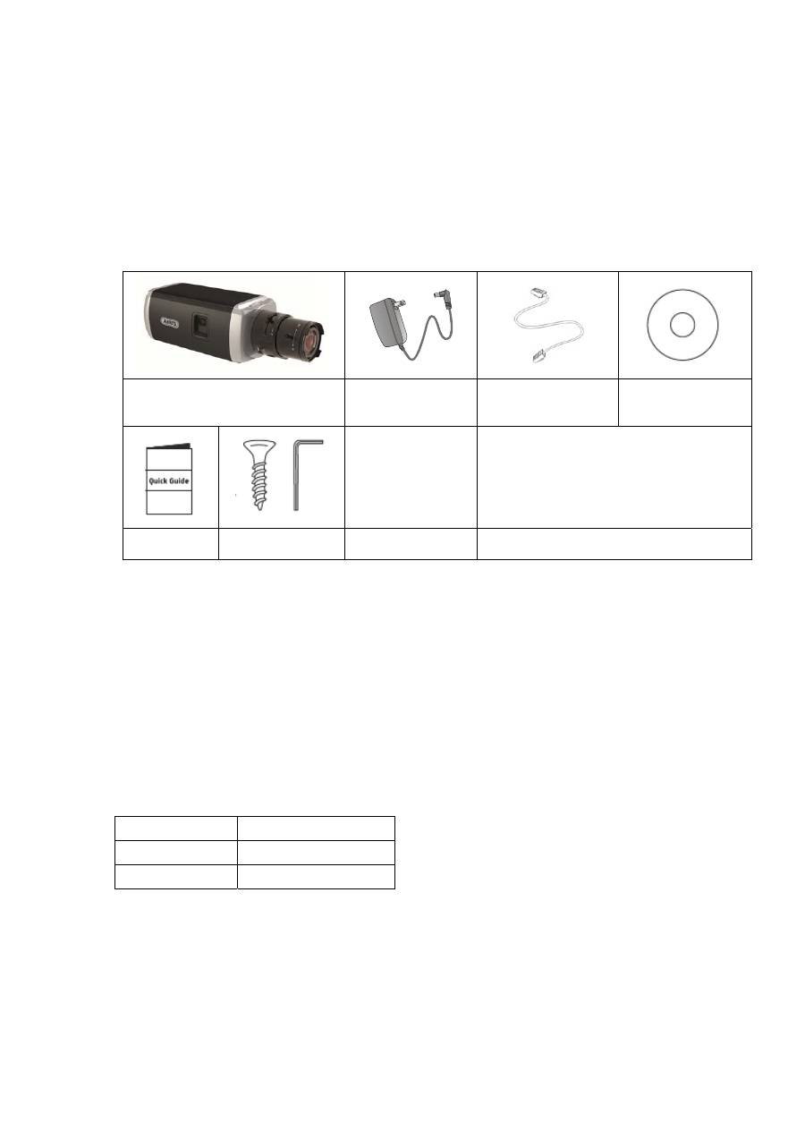
2. Scope of delivery
WDR Day/night HD 1080p
network camera (without lens)
Power supply unit
1 m network cable
CD ROM
Quick guide
Installation
material
3. Features and functions
HD 1080p resolution: 1920 x 1080 @ 25 fps
Camera for use in extreme backlighting situation
Day/night switching with electromechanical IR swivel filter (ICR)
Analogue video output for service purposes
Power over Ethernet (PoE)
ONVIF
compatible
4. Device description
Model number
TVIP52502
Resolution
1920 x 1080 (1080p)
WDR
√
66
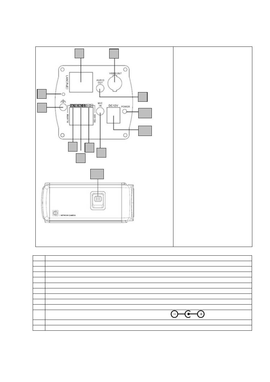
5.
Description of the connections
No. Description
1 Network
access
(RJ45)
2 Reset
button
3 Ground
connection
4
Alarm output (max. 5 V DC/50 mA)
5
Alarm input (IN/G) (jumper between “IN” and “G” triggers the alarm)
6
RS-485 (not in use)
7
Analogue video output (for service purposes)
8 Audio
output
9
Audio input (microphone/line)
10
12 V DC power supply connection (round plug 5.5 x 2.1 mm)
11
Status display for power supply
12 Lens
connection
1
2
3
4
5
6
7
8
9
10
11
12
67
6. Inital
start-up
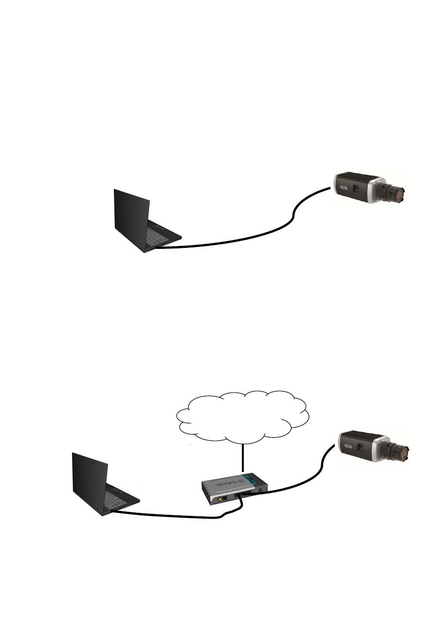
The network camera automatically detects whether a direct connection between the PC and camera
should be made. A crossover network cable is not required for this.
Direct connection of the network camera to a PC/laptop
1. Ensure that a CAT 5 network cable is used.
2. Connect the cable to the Ethernet interface of the PC/laptop and the network camera.
3. Connect the power supply to the network camera.
4. Configure the network interface of your PC/laptop to the IP address 192.168.0.2 default
gateway to 192.168.0.1
5. Go to 8, to finish the initial set-up and establish the connection to the network camera.
Connecting the network camera to a router/switch
1. Ensure that a CAT 5 network cable is used.
2. Connect the PC/laptop to the router/switch.
3. Connect the network camera to the router/switch.
4. Connect the power supply to the network camera.
5. If a DHCP server is available in your network, set the network interface of your PC/laptop to
“Obtain an IP address automatically”.
6. If no DHCP server is available, configure the network interface of your PC/laptop to
192.168.0.2 and the default gateway to 192.168.0.1
7. Go to point 8 to finish the initial set-up and establish the connection to the network camera.
7.
68
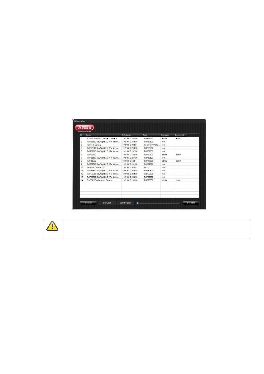
Accessing the network camera for the first time
The network camera is accessed for the first time using the IP Installer.
After the installation wizard is started, it searches for all connected ABUS network cameras and
video servers in your network.
You can find the program on the included CD-ROM. Install the program on your PC and then run
it.
If a DHCP server is available in your network, the IP address is assigned automatically for both the
PC/laptop and the network camera.
If no DHCP server is available, the network camera automatically sets the following IP address:
192.168.0.100.
Your PC system must be located in the same IP subnetwork in order to establish communication with
the network camera (PC IP address: e.g. 192.168.0.2).
The standard setting for the network camera is “DHCP”. If no DHCP server is in operation in
your network, then we recommend setting the IP address manually to a fixed value following
initial access to the network camera.

69
8. Password prompt
When delivered, an administrator password is already defined for the network camera. However, the
administrator should define a new password immediately for security reasons. After the new
administrator password is stored, the network camera asks for the user name and password every
time it is accessed.
The administrator account is set up in the factory as follows: User name “
admin
” and password
“
12345
”. Each time the network camera is accessed, the browser displays an authentication window
and asks for the user name and password. Should your individual settings for the administrator
account no longer be accessible, please contact our technical support team.
To enter a user name and password, proceed as follows:
Open Internet Explorer and enter the IP address for the camera (e.g. “http://192.168.0.100”).
You are then prompted for authentication:
->
You are now connected with the network camera and can see a video stream
.
70
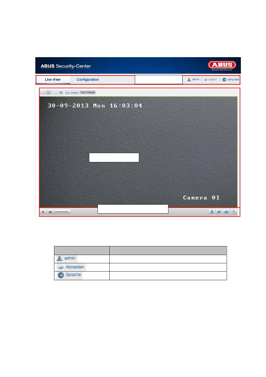
9. User functions
Open the main menu on the network camera. The interface is divided into the following main areas:
9.1 Menu bar
Select the appropriate tab: “Live View”, “Configuration” or “Log”.
Button
Description
Display of the user logged on
User logout
Selection of the desired language
Live image display
Menu bar
Audio / video control
71
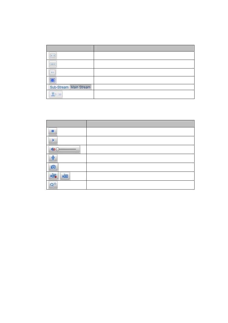
9.2 Live image display
You can access the full-screen view by double-clicking here.
Button
Description
Activate 4:3 view
Activate 16:9 view
Display original size
Adjust view to browser automatically
Selection of the streaming type for the live cast
Displaying/hiding the camera control
9.3 Audio / video control
Button
Description
Deactivate live cast
Activate live cast
Deactivate / activate audio, adjust volume
Microphone on / off
Instant image (snapshot)
Start / stop manual recording
Start / stop 3D zoom
72
10. Configuration
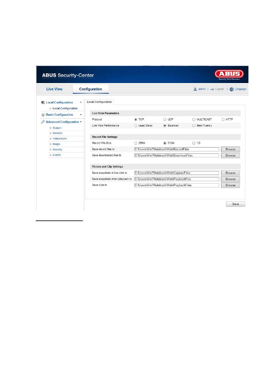
10.1 Local configuration
Under the “Local Configuration” menu item, you can make settings for the live view, file paths of the
recordings and snapshots.
Live View Parameters
Here you can set the protocol type and the live view performance of the camera.
Protocol
TCP:
Complete provision of streaming data and high video quality, however this affects real-time
transmission
UDP:
Real-time audio and video transmission
HTTP:
Provides the same quality as TCP, however special ports are not configured under the
network settings.
Live View Performance
You can set the performance level for the live view here.

73
Record File Settings
You can define the file size for recordings, the recording path and the path for downloaded files here. To
apply the changes, click “Save”.
Record File Size
You can select between 256 MB, 512 MB and 1 GB as the file size for recordings and downloaded videos.
Save record files to
You can determine the file path that is to be used to manual recordings here.
The default path is C:\\<User>\<Computer_Name>\Web\RecordFiles.
Save downloaded files to
You can store the file path for downloaded videos here.
The following path is set by default: C:\\<User>\<Computer_Name>\Web\DownloadFiles
Picture and Clip Settings
Here you can store the path for snapshots taken during playback as well as for video clips.
Save snapshots in live view to
Select the file path for snapshots from the live view.
The following path is set by default: C:\\<User>\<Computer_Name>\Web\CaptureFiles
Save snapshots when playback to
You can store the path here for saving snapshots taken during playback.
The following path is set by default: C:\\<User>\<Computer_Name>\Web\PlaybackPics
Save clips to
You can specify the memory path for storing video clips here.
The following path is set by default: C:\\<User>\<Computer_Name>\Web\PlaybackFiles
74
10.2 Basic configuration
All settings that can be made under “Basic Configuration” can also be found under the menu item
“Advanced Configuration”. Please take note of the “Available in mode” column in the descriptions of the
“Advanced Configuration”.
75
10.3 Advanced Configuration
10.3.1 System
Menu item
Description
Available in mode
Device Information
Display of device information
Basic Configuration,
Advanced
Configuration
Time Settings
Configuration of the time specification Basic
Configuration,
Advanced
Configuration
Maintenance
System maintenance settings
Basic Configuration,
Advanced
Configuration
DST
(Daylight Saving
Time)
Configuration of the automatic daylight savings
time switch
Advanced
Configuration
76
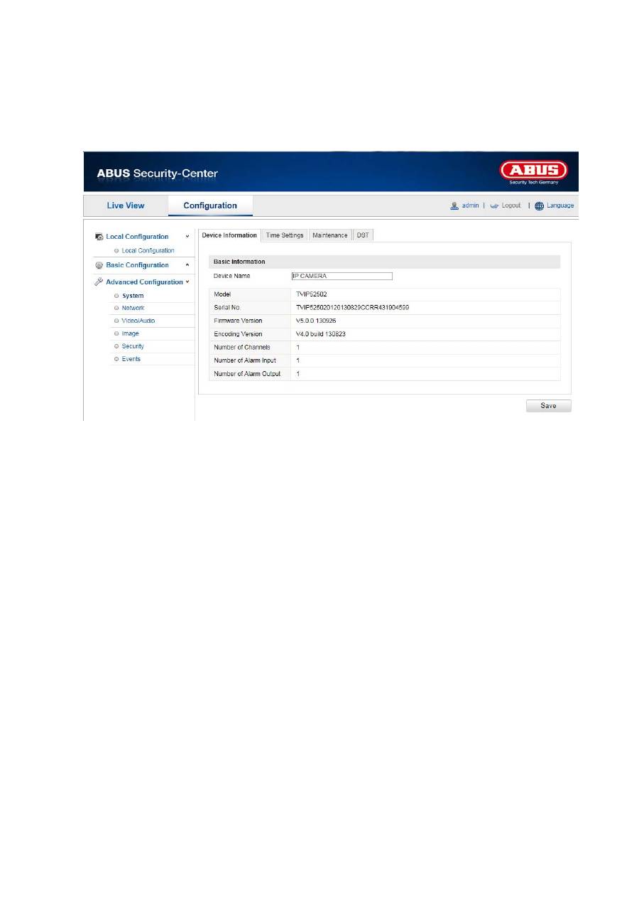
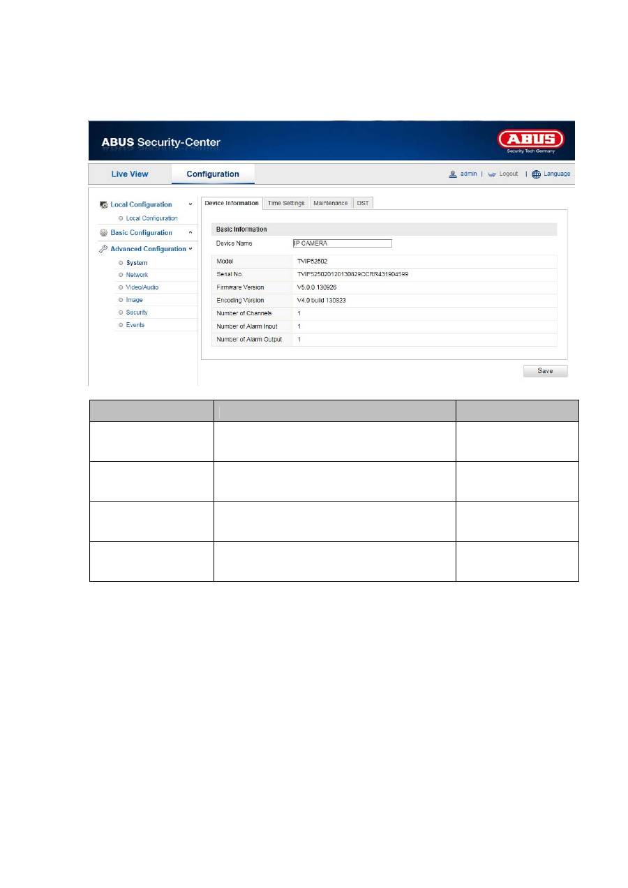
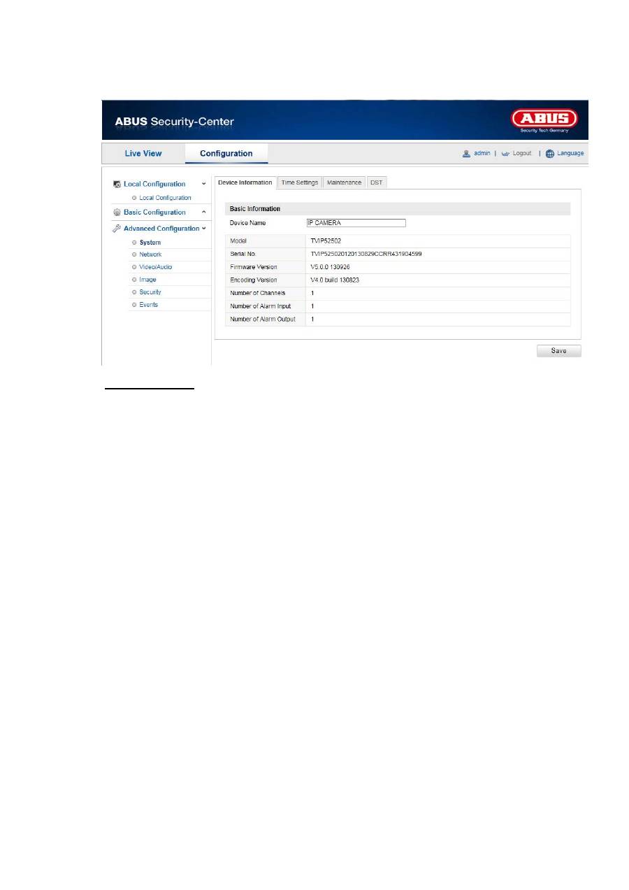
10.3.1.1 Device Information
Basic Information
Device Name
You can specify a device name for the Speed Dome here. Click on “Save” to apply the change.
Model
Model number display
Serial No.
Serial number display
Firmware Version
Firmware version display
Encoding Version
Encoding version display
Number of Channels
Display of the number of channels
Number of Alarm Input
Display of the number of alarm inputs
Number of Alarm Output
Display of the number of alarm outputs
77
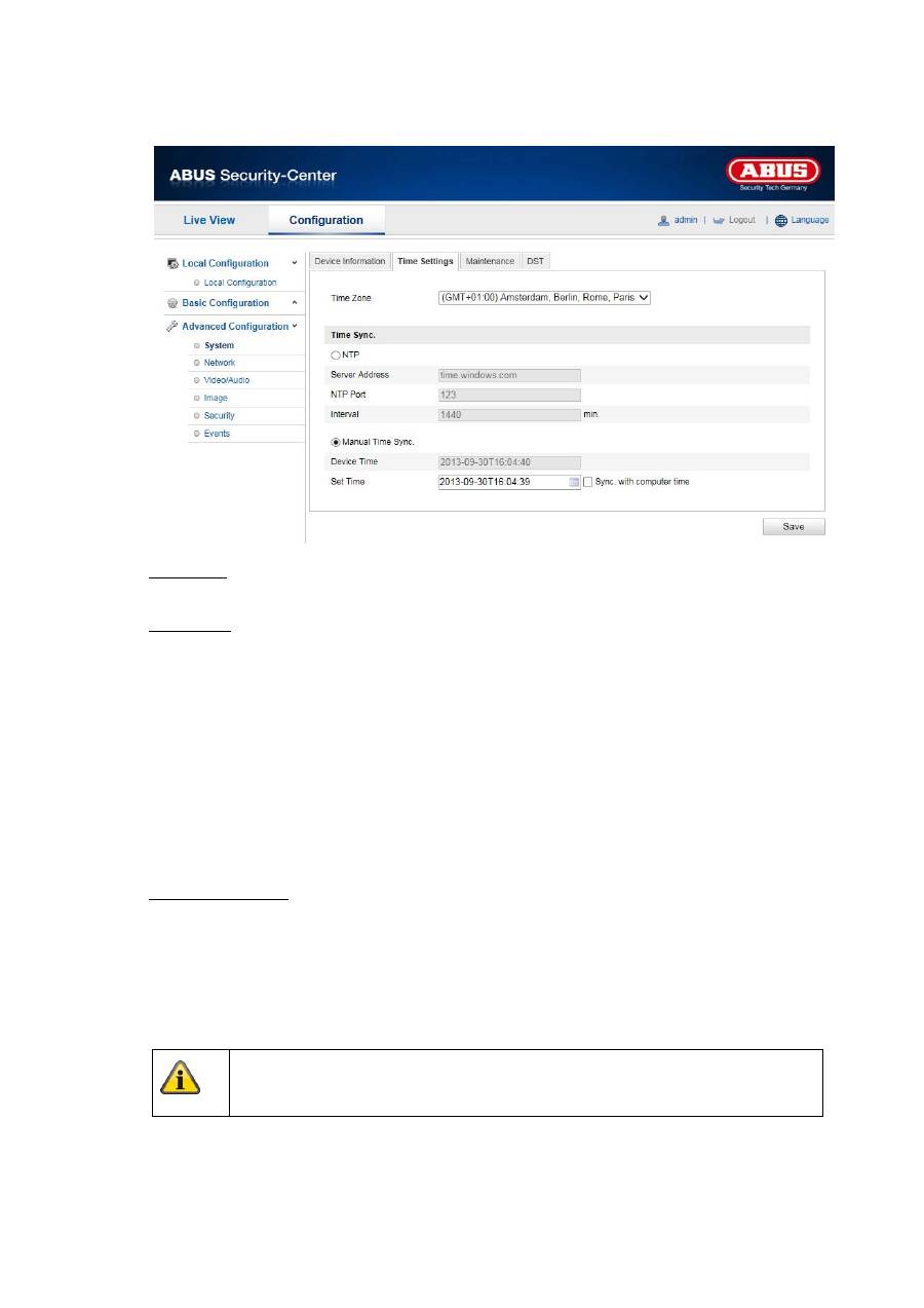
10.3.1.2 Time Settings
Time Zone
Time zone selection (GMT)
Time Sync.
NTP
Using the Network Time Protocol (NTP) it is possible to synchronise the time of the Speed Dome with
a time server.
Activate NTP to use this function.
Server Address
IP server address of the NTP server.
NTP Port
Network port number of the NTP service (default: port 123)
Manual Time Sync.
Device Time
Computer device time display
Set Time
Display of the current time using the time zone setting.
Click on “Sync. with computer time” to adopt the device time of the computer.
Apply the settings made with “Save”.
78
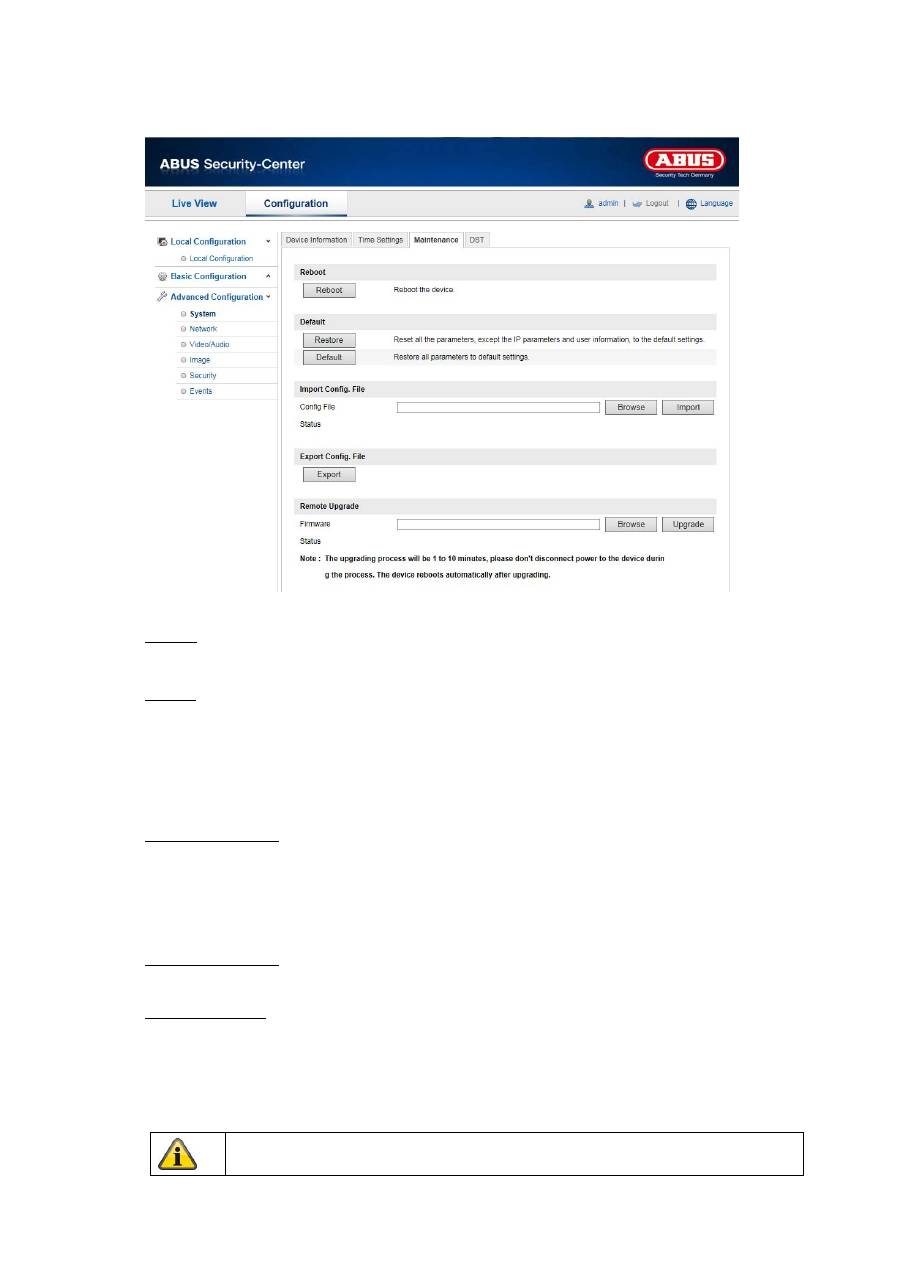
10.3.1.3 Maintenance
Reboot
Click “Reboot” to restart the device.
Default
Restore
Click “Restore” to reset all the parameters to the default settings, with the exception of the IP
parameters.
Default
Select this item to reset all parameters to the default values.
Import Config. File
Config. File
Select a file path to import a configuration file here.
Status
Display of the import status
Export Config. File
Click “Export” to export a configuration file.
Remote Upgrade
Firmware
Select the path to update the Speed Dome with new firmware.
Status
Display of the update status
Apply the settings made with “Save”.
79
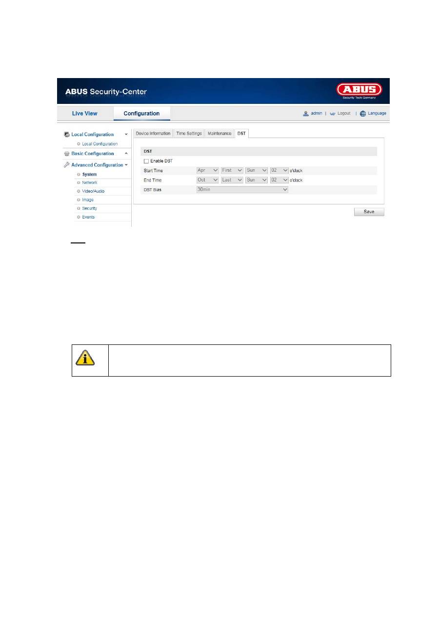
10.3.1.4 DST
DST
Enable DST
Activate the “Enable DST” checkbox to adjust the system time automatically to summer time.
Start Time
Specify the time for switching to summer time.
End Time
Specify the time for switching to winter time.
Apply the settings made with “Save”.
80
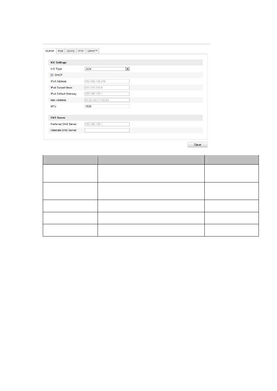
10.3.2 Network
Menu item
Description
Available in mode
TCP/IP
Settings of the TCP/IP data
Basic Configuration,
Advanced
Configuration
Port
Settings for the used ports
Basic Configuration,
Advanced
Configuration
DDNS
Settings for the DDNS data
Advanced
Configuration
FTP
Settings for the FTP data
Advanced
Configuration
UPnP™
Settings for the UPnP data
Advanced
Configuration
