Rothenberger ROTEST GW 150/4: instruction
Class: Measuring Instruments
Type:
Manual for Rothenberger ROTEST GW 150/4
ROTEST GW 150/4
ROTEST GW 150/4
Bedienungsanleitung
Instructions for use
Instruction d’utilisation
Instrucciones de uso
Istruzioni d’uso
Gebruiksaanwijzing
Instruções de serviço
Brugsanvisning
Bruksanvisning
Bruksanvisning
61700
Käyttöohje
Instrukcja obslugi
61701
Návod k používání
Kullanim kilavuzu
Kezelési útmutató
Οδηγίες χρήσεως
Инструкция по использованию
www.rothenberger.com
A
Overview
8 9 10
7
12
B
5
17
C
16
D
2
3
35
A
37
15
22*
21
36
13
6
14
B
Technical Data

Intro
DEUTSCH - Originalbetriebsanleitung!
Seite 2
Bedienungsanleitung bitte lesen und aufbewahren! Nicht wegwerfen!
Bei Schäden durch Bedienungsfehler erlischt die Garantie! Technische Änderungen vorbehalten!
ENGLISH
page 9
Please read and retain these directions for use. Do not throw them away! The warranty does not cover
damage caused by incorrect use of the equipment! Subject to technical modifications!
page 15
FRANÇAIS
Lire attentivement le mode d’emploi et le ranger à un endroit sûr! Ne pas le jeter ! La garantie est
annulée lors de dommages dûs à une manipulation erronée ! Sous réserve de modifications techniques!
ESPAÑOL
página 22
¡Por favor, lea y conserve el manual de instrucciones! ¡No lo tire! ¡En caso de daños por errores de
manejo, la garantía queda sin validez! Modificaciones técnicas reservadas!
ITALIANO
pagina 28
Per favore leggere e conservare le istruzioni per l´uso! Non gettarle via! In caso di danni dovuti ad errori
nell´uso, la garanzia si estingue! Ci si riservano modifiche tecniche!
NEDERLANDS
bladzijde 35
Lees de handleiding zorgvuldig door en bewaar haar goed! Niet weggooien! Bij schade door
bedieningsfouten komt de garantieverlening te vervallen! Technische wijzigingen voorbehouden!
PORTUGUES
pagina 42
Queiram ler e guardar o manual de instruções! Não deitar fora! Em caso de avarias por utilização
incorrecta, extingue-se a garantia! Reservado o direito de alterações técnicas!
DANSK
side 49
Læs betjeningsvejledningen, og gem den til senere brug! Smid den ikke ud! Skader, som måtte opstå som
følge af betjeningsfejl, medfører, at garantien mister sin gyldighed! Ret til tekniske ændringer forbeholdes!
SVENSKA
sida 55
Läs igenom bruksanvisningen och förvara den väl! Kasta inte bort den! Garantin upphör om apparaten
har använts eller betjänats på ett felaktigt sätt! Med reservation för tekniska ändringar!
NORSK
side 61
Les bruksanvisningen og oppbevar den vel! Ikke kast den! Oppstår skader på grunn av betjeningsfeil
opphører garantiens gyldighet! Tekniske forandringer forbeholdes!
SUOMI
sivulta 67
Lue ja säilytä tämä käyttöohje! Älä heitä pois!
Takuu ei kata käyttövirheistä aiheutuvia vahinkoja! Oikeudet teknisiin muutoksiin pidätetään!
POLSKI
strony 73
Instrukcjê obslugi prosze przeczytac i przechowac! Nie wyrzucac!
Przy uszkodzeniach wynikajacych z blêdów obslugi wygasa gwarancja! Zmiany techniczne zastrzezone!
CESKY
stránky 80
Návod k obsluze si prosím prectete a uschovejte jej! Nevyhazujte jej!
V prípade poškození zpusobeném chybnou obsluhou zaniká záruka! Technické zmeny jsou vyhrazeny!
TÜRKÇE
sayfa 86
Kullanim açiklamalarini lütfen dikkatlice okuyunuz ve bir yerde muhafaza ediniz! Çöpe atmayiniz!
Kullaniminda yapilan hatalar, garantinin silinmesine neden olur! Teknik deðiþiklikler yapma hakkimiz saklidir!
MAGYAR
oldaltól 93
Kérjük, olvassa el és õrizze meg a kezelési utasítást! Ne dobja el!
A helytelen kezelésbõl származó károsodások esetén megszûnik a jótállás! Mûszaki változtatások fenntartva!
ΕΛΛΗΝΙΚΑ
100Σελίδα
Οδηγίες χειρισμού παρακαλείσθε να τις διαβάσετε και να τις φυλάσσετε! Μην τις πετάξετε!
Σε ζημιες από σφάλματα χειρισμού παυει να ισχύει η εγγύηση! Με επιφύλαξη για τεχνικές αλλαγές!
PУCCKИЙ
Страница 107
Прочтите инструкцию по эксплуатации и сохраняйте её для дальнейшего использования! B случае поломки инструмента
из-за несоблюдения инструкции клиент теряет право на обслуживание по гарантии! Bозможны технические изменения!
1
Inhalt Seite
1 Hinweise zur Sicherheit 3
1.1 Bestimmungsgemäßer Gebrauch 3
1.2 Hinweise zur Sicherheit von Mensch und Gerät 3
2 Einzelteile und Bedienelemente des ROTEST GW 150/4 (Abb.A) 3
3 Technische Daten 4
4 Eigenprüfung als Funktionssicherheitsprüfung 4
4.1 Eigenprüfung mit Handpumpe (3) und Verbindungsschlauch (6) 4
4.2 Eigenprüfung mit Einfachgebläse (12), Wassersäule und
Verbindungsschlauch (6) 4
5 Bedienung und Durchführung von Prüfungen mit dem ROTEST GW 150/4 5
5.1 Belastungsprüfung von Gas-Hausinstallationen gemäß DVGW-TRGI (G600) 5
5.2 Dichtheitsprüfung von Gas-Hausinstallationen gemäß DVGW-TRGI (G600) 5
5.3 Einstellung des Düsenvordruckes an atmosphärischen- und Gebläsebrennern
mit Wassersäule bis 30 mbar 6
5.4 Vorprüfung von Trinkwasser-Hausinstallationen 6
5.5 Hauptprüfung von Trinkwasser-Hausinstallationen 7
6 Prüfprotokoll 7
7 Außerbetriebnahme 7
8 Wartung und Pflege 8
9 Zubehör 8
10 Entsorgung 8
Kennzeichnungen in diesem Dokument
Gefahr
Dieses Zeichen warnt vor Personenschäden.
Achtung
Dieses Zeichen warnt vor Sach- oder Umweltschäden.
Aufforderung zu Handlungen
2 DEUTSCH
1 Hinweise zur Sicherheit
1.1 Bestimmungsgemäßer Gebrauch
Das Prüfgerät ROTEST GW 150/4 mit seinen zugehörigen Elementen (im Koffer beiliegend) darf
ausschließlich von Fachpersonal mit Kenntnissen der Versorgungstechnik für Dichtheitsprüfungen
von Rohrleitungen und Behältern gemäß der folgenden Anleitung verwendet werden. Dies betrifft
insbesondere folgende Einsatzbereiche:
Belastungsprüfung von Gas-Hausinstallationen gemäß DVGW-TRGI (G600, April 2008)
Dichtheitsprüfung von Gas-Hausinstallationen gemäß DVGW-TRGI (G600, April 2008)
Eigenprüfung als Funktionssicherheitsprüfung mit Handpumpe, Verbindungsschlauch und
Adapter mit Absperrventil
Eigenprüfung als Funktionssicherheitsprüfung mit Einfachgebläse, Wassersäule,
Verbindungsschlauch und Absperrventil
Dichtheitsprüfung für Propan-Flüssiggasleitungen mit Wassersäule bis 150 mbar und
Niederdruck-Flüssiggasleitungen mit Wassersäule bis 60 mbar
Einstellung des Düsenvordruckes an atmosphärischen- und Gebläsebrennern mit Wassersäule
bis 30 mbar
Überprüfung des Geräteanschlussdruckes an Gasgeräten mit Wassersäule bis 30 mbar
Vorprüfung und Hauptprüfung von Trinkwasser-Hausinstallationen nach DIN 1988 (TRWI) mit
Luft
1.2 Hinweise zur Sicherheit von Mensch und Gerät
Führen Sie keinerlei Arbeiten in Inneren des Gerätes aus! In diesem Bereich darf
ausschließlich geschultes Fachpersonal (Kundendienst) tätig werden!
Befolgen Sie die Sicherheitshinweise des Anlagen- bzw. Rohrherstellers sowie die
Hinweise zur Sicherheit der Hersteller der Verbindungselemente!
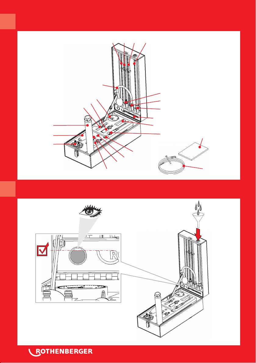
2 Einzelteile und Bedienelemente des ROTEST GW 150/4 A
2 Tank 10 Steckrohr (121-155 mbar) 21 Adapter für Gasgeräte
3 Handpumpe 12 Einfachgebläse 22* Einrohrzählerkappe
5 Manometer 13 Gasprüfstopfen Gr. 0 konisch 35 Pflegefett für O-Ringe
6 Verbindungsschlauch 14 Gasprüfstopfen Gr. 1 konisch 36 O-Ringe
7 Steckrohr festinstalliert 15 Gasprüfstopfen Gr. 2 konisch 37 Betriebsanleitung
8 Steckrohr (41–75 mbar) 16 Gasprüfstopfen Gr. 1 zylindrisch
9 Steckrohr (81-115 mbar) 17 Gasprüfstopfen Gr. 2 zylindrisch
* = Zubehör bei Ausführung 6.1701
DEUTSCH 3
3 Technische Daten
Prüfgenauigkeit Manometer 0,1 bar (Anzeigenbereich 0 – 4 bar)
Wassersäule gemäß TRGI mit einer Ablesegenauigkeit von
0,1mbar.
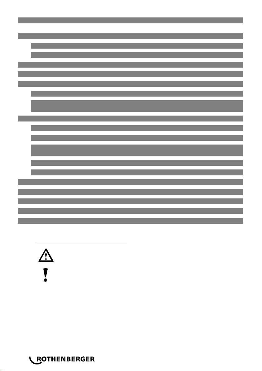
Befüllung des Wassertanks Das Gerät wird mit gefülltem Wassertank (2) angeliefert. Sollte
Wasser nicht in ausreichender Menge im Tank sein, siehe Abb. B.
Sie dürfen weder destilliertes Wasser noch Wasser mit Zusätzen wie Alkohol, Spiritus
oder ähnliches zur Befüllung verwenden! Dadurch verändert sich die
Oberflächenspannung der Flüssigkeit und die Messergebnisse werden verfälscht. Bei
Temperaturen unter 0 °C, darf das Gerät nicht eingesetzt werden. Es besteht die
akute Gefahr von Frostschäden am Wasserbehälter, den Absperrventilen und den
Steckrohren.
Hierfür übernimmt ROTHENBERGER keine Gewährleistung.
4 Eigenprüfung als Funktionssicherheitsprüfung
Vor Inbetriebnahme des Gerätes – bzw. in regelmäßigen zeitlichen Abständen – ist die
Funktionssicherheit des Gerätes durch eine Eigenprüfung zu kontrollieren und sicherstellen.
4.1 Eigenprüfung mit Handpumpe (3) und Verbindungsschlauch (6)
Schließen Sie sämtliche Absperrventile Ihres ROTEST GW 150/4.
Stecken Sie den Verbindungsschlauch (6) mit hörbarem Rastgeräusch auf den Stecknippel von
Anschluss A.
Bringen Sie das System durch Pumpen mit der Handpumpe auf einen Prüfdruck von 3 bar.
Warten Sie den Temperaturausgleich über eine Zeit von 10 Minuten ab, um der
eingebrachten Luft die Möglichkeit zur Erwärmung oder Abkühlung zu geben.
Bei größeren Temperaturänderungen ist die Ausgleichszeit zu verlängern!
Führen Sie die Prüfung über eine Prüfzeit von 10 Minuten durch. Während dieser Zeit darf der
angezeigte Druck nicht fallen.
4.2 Eigenprüfung mit Einfachgebläse (12), Wassersäule und Verbindungsschlauch (6)
Schließen Sie sämtliche Absperrventile Ihres ROTEST GW 150/4.
Stecken Sie den Verbindungsschlauch (6) mit hörbarem Rastgeräusch auf den Stecknippel von
Anschluss B.
Montieren Sie Steckrohrsystem wie folgt:
- Schieben Sie das Steckrohr (8) mit der Skala 41-75 mbar durch leichte Drehung in das
fest installierte Steckrohr (7).
- Schieben Sie nun das Steckrohr (9) mit der Skala 81-115 mbar durch leichte Drehung in
das Steckrohr (8).
Öffnen Sie die Absperrventile der Anschlüsse B, C und D.
Bringen Sie das System durch Pumpen mit dem Einfachgebläse (12) auf den Prüfdruck von
110 mbar.
Schließen Sie das Absperrventil von Anschluss C, da sonst ein Druckabfall eintreten kann.
Warten Sie den Temperaturausgleich über eine Zeit von 10 Minuten ab, um der
eingebrachten Luft die Möglichkeit zur Erwärmung oder Abkühlung zu geben.
Bei größeren Temperaturänderungen ist die Ausgleichszeit zu verlängern!
Führen Sie die Prüfung über eine Prüfzeit von 10 Minuten durch. Während dieser Zeit darf der
angezeigte Druck nicht fallen.
4 DEUTSCH

5 Bedienung und Durchführung von Prüfungen mit dem ROTEST GW 150/4
5.1 Belastungsprüfung von Gas-Hausinstallationen gemäß DVGW-TRGI (G600)
Folgende Punkte sind zu berücksichtigen:
Die Belastungsprüfung ist bei neu verlegten Leitungen ohne Armaturen durchzuführen.
Für die Dauer der Prüfung müssen alle Leitungsöffnungen mit Stopfen, Kappen,
Steckscheiben oder Blindflanschen aus metallenen Werkstoffen dicht verschlossen sein.
Verbindungen mit gasführenden Leitungen sind unzulässig.
Führen Sie die Belastungsprüfung durch, bevor die Leitungen verputzt oder verdeckt und ihre
Verbindungen beschichtet oder umhüllt sind.
Sollte die Prüfung vom Anschluss für einen Gaseinrohrzähler her erfolgen, wird die Leitung
am Anschlussventil mit der Einrohrzählerkappe mit Gewindeanschluss (22) verschlossen.
Gehen Sie wie folgt vor:
Schließen Sie sämtliche Absperrventile Ihres ROTEST GW 150/4.
Stecken Sie den Verbindungsschlauch (6) mit hörbarem Rastgeräusch auf den Stecknippel von
Anschluss A.
Setzen Sie einen passenden Prüfstopfen in das offene Leitungsende ein und bringen Sie den
Stopfengummi durch Drehen der Flügelmutter zur Ausdehnung, bis der Stopfen festsitzt und
dicht ist.
Stecken Sie das freie Ende des Verbindungsschlauches (6) auf den Anschluss am Prüfstopfen.
Bringen Sie das System durch Pumpen mit der Handpumpe auf einen Prüfdruck von 1 bar.
Warten Sie den Temperaturausgleich über eine Zeit von 10 Minuten ab, um der
eingebrachten Luft die Möglichkeit zur Erwärmung oder Abkühlung zu geben.
Bei starken Temperatur- oder Luftdruckänderungen reichen 10 Minuten nicht aus! In
Abhängigkeit von Temperatur- oder Druckänderungen kann die Ausgleichszeit bis zu
zwei Stunden dauern!
Führen Sie die Prüfung über eine Prüfzeit von 10 Minuten durch. Während dieser Zeit darf der
angezeigte Druck nicht fallen.
5.2 Dichtheitsprüfung von Gas-Hausinstallationen gemäß DVGW-TRGI (G600)
Für Propan-Flüssiggasleitungen mit Wassersäule bis 150 mbar
Für Niederdruck Flüssiggasleitungen mit Wassersäule bis 40-60 mbar
Folgende Punkte sind zu berücksichtigen:
Die Dichtheitsprüfung erstreckt sich auf die Leitungen einschließlich der Armaturen, jedoch
ohne Gasgeräte sowie zugehörige Regel- und Sicherheitseinrichtungen.
Verbindungen mit gasführenden Leitungen sind unzulässig.
Die Dichtheitsprüfung ist durchzuführen, bevor die Leitungen verputzt oder verdeckt und ihre
Verbindungen beschichtet oder umhüllt sind.
Der Gaszähler kann in die Dichtheitsprüfung mit einbezogen werden.
Erfolgt die Prüfung vom Anschluss für einen Gaseinrohrzähler, verschließen Sie die Leitung am
Anschlussventil mit einer Einrohrzählerkappe mit Gewindeanschluss (22).
Gehen Sie wie folgt vor:
Schließen Sie sämtliche Absperrventile Ihres ROTEST GW 150/4.
Stecken Sie den Verbindungsschlauch (6) mit hörbarem Rastgeräusch auf den Stecknippel von
Anschluss B.
Setzen Sie einen passenden Prüfstopfen in das offene Leitungsende ein und bringen Sie den
Stopfengummi durch Drehen der Flügelmutter zur Ausdehnung, bis der Stopfen festsitzt und
dicht ist.
Stecken Sie das freie Ende des Verbindungsschlauches (6) auf den Anschluss am Prüfstopfen.
DEUTSCH 5
Montieren Sie das Steckrohrsystem wie folgt:
- Schieben Sie das Steckrohr (8) mit der Skala 41-75 mbar durch leichte Drehung in das
fest installierte Steckrohr (7).
- Schieben Sie nun das Steckrohr (9) mit der Skala 81-115 mbar durch leichte Drehung in
das Steckrohr (8).
- Schieben Sie jetzt das Steckrohr (10) mit der Skala 121-155 mbar durch leichte Drehung
in das Steckrohr (9)
Öffnen Sie die Absperrventile der Anschüsse B, C und D.
Bringen Sie das System durch Pumpen mit dem Einfachgebläse (12) auf den Prüfdruck von
150 mbar.
Schließen Sie das Absperrventil von Anschluss C, da sonst ein Druckabfall eintreten kann.
Warten Sie den Temperaturausgleich über eine Zeit von 10-60 Minuten (abhängig vom
Leitungsvolumen) ab, um der eingebrachten Luft die Möglichkeit zur Erwärmung oder
Abkühlung zu geben.
Bei starken Temperatur- oder Luftdruckänderungen reichen 10-60 Minuten
nicht aus! In Abhängigkeit von Temperatur- oder Druckänderungen kann die
Ausgleichszeit bis zu zwei Stunden dauern!
Führen Sie die Prüfung über eine Prüfzeit von 10-30 Minuten (abhängig vom
Leitungsvolumen) durch. Während dieser Zeit darf der angezeigte Druck nicht fallen.
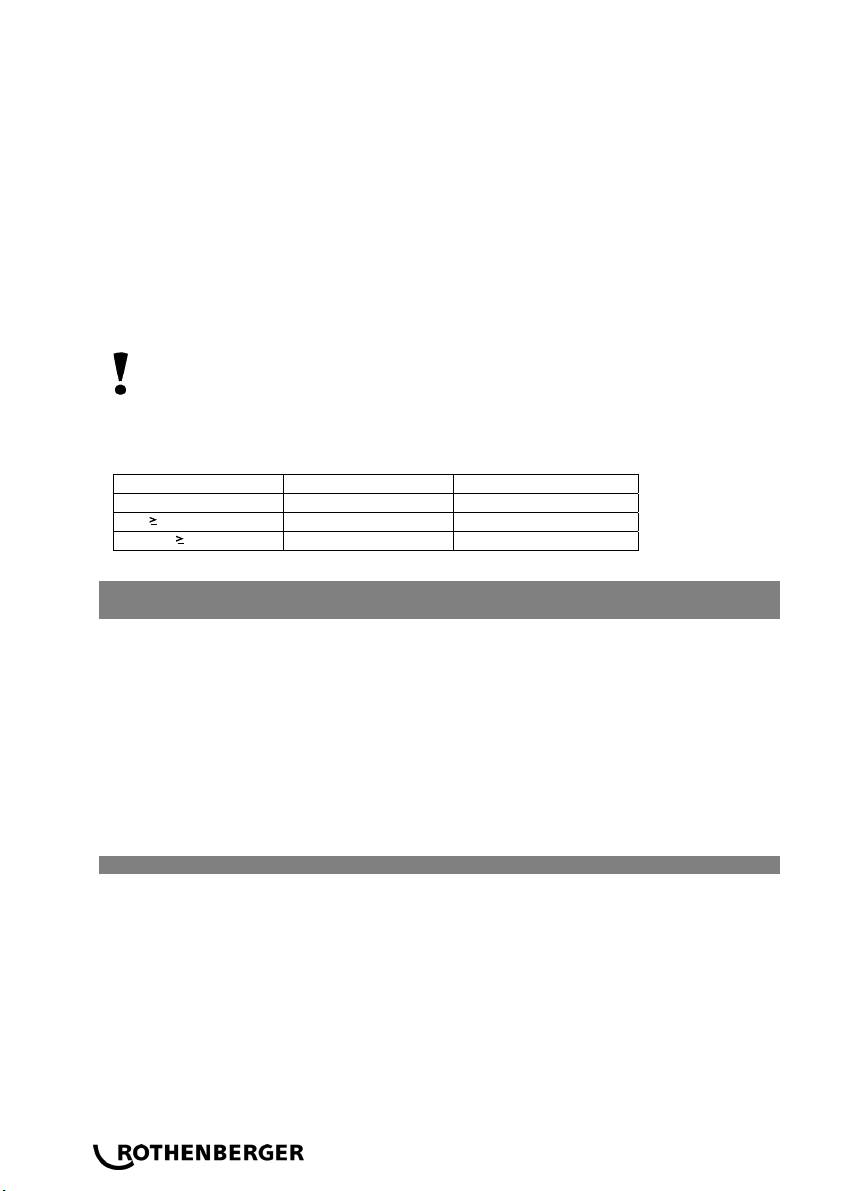
Dichtheitsprüfung: Anpassungszeiten und Prüfdauer in Abhängigkeit vom Leitungsvolumen
Leitungsvolumen* Anpassungszeit mind. Prüfdauer
< 100 l 10 min. 10 min.
100 l < 200l 30 min. 20 min.
200l 60 min. 30 min.
*Richtwerte
5.3 Einstellung des Düsenvordruckes an atmosphärischen- und Gebläsebrennern
mit Wassersäule bis 30 mbar
Gehen Sie wie unter Pkt. 5.2 vor:
Ein fest installiertes Steckrohr (7) bis 30 mbar ist hierfür ausreichend.
Schließen Sie den Adapter für Gasgeräte (21) an das freie Ende des Verbindungsschlauches
(6) an.
Stecken Sie die Tülle des Adapters für Gasgeräte (21) auf den Prüfanschluss für den
Düsenvordruck Ihres Gasbrenners auf.
Stellen Sie das Gasgerät so an, dass der Brenner mit voller Brennbelastung läuft.
Öffnen Sie die Absperrventile der Anschlüsse B und D.
Lesen Sie jetzt den tatsächlich vorhandenen Düsenvordruck ab.
5.4 Vorprüfung von Trinkwasser-Hausinstallationen
Gehen Sie wie folgt vor:
Schließen Sie sämtliche Absperrventile Ihres ROTEST GW 150/4.
Stecken Sie den Verbindungsschlauch (6) mit hörbarem Rastgeräusch auf den Stecknippel von
Anschluss A.
Stecken Sie das freie Ende des Verbindungsschlauches (6) mit hörbarem Rastgeräusch auf den
Stecknippel Ihres Adapters am Rohrende.
Bringen Sie das System durch Pumpen mit der Handpumpe (3)
- bei Nennweiten bis DN 50 auf einen Prüfdruck von maximal 3 bar
- bei Nennweiten über DN 50 bis DN 100 auf einen Prüfdruck von max. 1 bar.
6 DEUTSCH

Warten Sie den Temperaturausgleich über eine Zeit von 10 Minuten ab, um der
eingebrachten Luft die Möglichkeit zur Erwärmung oder Abkühlung zu geben.
Bei starken Temperatur- oder Luftdruckänderungen reichen 10 Minuten nicht aus! In
Abhängigkeit von Temperatur- oder Druckänderungen kann die Ausgleichszeit bis zu
zwei Stunden dauern!
Führen Sie die Prüfung über eine Prüfzeit von 10 Minuten durch. Während dieser Zeit darf der
angezeigte Druck nicht fallen.
5.5 Hauptprüfung von Trinkwasser-Hausinstallationen
Gehen Sie wie folgt vor:
Schließen Sie sämtliche Absperrventile Ihres ROTEST GW 150/4.
Stecken Sie den Verbindungsschlauch (6) mit hörbarem Rastgeräusch auf den Stecknippel von
Anschluss B.
Setzen Sie einen passenden Prüfstopfen in das offene Leitungsende ein und bringen Sie den
Stopfengummi durch Drehen der Flügelmutter zur Ausdehnung, bis der Stopfen festsitzt und
dicht ist.
Stecken Sie das freie Ende des Verbindungsschlauches (6) auf den Anschluss am Prüfstopfen.
Montieren Sie das Steckrohrsystem wie folgt:
- Schieben Sie das Steckrohr (8) mit der Skala 41-75 mbar durch leichte Drehung in das
fest installierte Steckrohr (7).
- Schieben Sie nun das Steckrohr (9) mit der Skala 81-115 mbar durch leichte Drehung in
das Steckrohr (8).
Öffnen Sie die Absperrventile der Anschlüsse B, C und D.
Bringen Sie das System durch Pumpen mit dem Einfachgebläse (12) auf den Prüfdruck von
110 mbar.
Schließen Sie das Absperrventil von Anschluss C, da sonst ein Druckabfall eintreten kann.
Warten Sie den Temperaturausgleich über eine Zeit von 10 Minuten ab, um der
eingebrachten Luft die Möglichkeit zur Erwärmung oder Abkühlung zu geben.
Bei starken Temperatur- oder Luftdruckänderungen reichen 10 Minuten nicht aus! In
Abhängigkeit von Temperatur- oder Druckänderungen kann die Ausgleichszeit bis zu
zwei Stunden dauern!
Führen Sie die Prüfung
- bis zu 100 Liter Leitungsvolumen über eine Prüfzeit von mindestens 30 Minuten durch.
Erhöhen Sie die Prüfzeit
- für je weitere 100 Liter Leitungsvolumen um 10 Minuten.
6 Prüfprotokoll
Der verantwortliche Fachmann muss nach Beendigung der jeweiligen Prüfung ein Druckprotokoll
erstellen.
7 Außerbetriebnahme
Demontieren Sie nach der Dichtheitsprüfung den Verbindungsschlauch (6) und öffnen Sie das
Absperrventil am Anschluss D, damit die Wassersäule in den Tank (2) ablaufen kann.
Demontieren Sie die Steckrohre und plazieren diese an ihrem vorgesehenen Platz im
Stahlblechkoffer Ihres ROTEST GW 150/4.
Schließen Sie alle Absperrventile und klappen Sie die Pumpe ein.
DEUTSCH 7

8 Wartung und Pflege
Versehen Sie regelmäßig mit dem beiliegenden Silikon-Pflegefett die O-Ringe der Steckrohre, die
Steckkupplungen und die Gaszählerkappe!
Versehen Sie auch die Rohraufweitungen an den Steckrohren innen mit Fett, um die Montage zu
erleichtern!
Lagern Sie den Stahlblechkoffer sauber und trocken, damit innenliegende Teile nicht korrodieren!
Korrosion an den Ventilen beeinträchtigt deren Funktion!
Behandeln Sie den ROTEST GW 150/4 mit Sorgfalt!
9 Zubehör
Geeignetes Zubehör und ein Bestellformular finden Sie ab Seite 114.
10 Entsorgung
Teile des Gerätes sind Wertstoffe und können der Wiederverwertung zugeführt werden.
Hierfür stehen zugelassene und zertifizierte Verwerterbetriebe zur Verfügung. Zur
umweltverträglichen Entsorgung der nicht verwertbaren Teile (z.B. Elektronikschrott) befragen Sie
bitte Ihre zuständige Abfallbehörde.
8 DEUTSCH
Contens Page
1 Safety instructions 10
1.1 Proper use 10
1.2 Operator and equipment safety 10
2 Components and Operator Controls (fig. A) 10
3 Technical data 11
4 Built-in safety tests 11
4.1 Built-in hand pump (3) and connecting hose (6) test 11
4.2 Built-in bellow (12), water column and connecting hose (6) test 11
5 Operating and performing tests with the ROTEST GW 150/4 12
5.1 Bearing test of gas fittings pursuant to 1* 12
5.2 Leak test of gas fittings pursuant to 1* 12
5.3 Adjustment of gas admission pressure to atmospheric and blower
burners using water column up to 30 mbar 13
5.4 Initial test of drinking water systems of domestic connections 13
5.5 Principle test of drinking water systems for domestic connections
pursuant to 1* 14
6 Test protocol 14
7 Disassembly 14
8 Maintenance and care 14
9 Accessories 14
10 Disposal 14
Markings in this document
Danger
This sign warns against the danger of personal injuries.
Caution
This sign warns against the danger of property damage and damage to the
environment.
Call for action
1* Statutory regulations in the country of use or the respective manufacturer and facility instructions and guidelines
ENGLISH 9
1 Safety instructions
1.1 Proper use
The ROTEST GW 150/4 test instrument and its components (included in carrying case) should only
be operated by skilled personnel competent in gas and water supply engineering in particular in
leakage tests for pipes and containers. All tests must be carried out in accordance with the
present instructions, in particular the following tests:
Bearing tests for gas fittings pursuant to 1*
Leak tests of gas fittings pursuant to 1*
Built-in hand pump, connecting hose and adapter with cut-off valve safety tests
Built-in bellow, water column, connecting hose and cut-off valve safety tests
Leak test of propane liquid gas fittings and low-pressure liquid gas fittings pursuant to 1*
Adjustment of gas admission pressure to atmospheric and blower burners using a water
column up to 30 mbar
Examination and inspection of gas appliance connection pressure pursuant to 1*
Initial air-and principle air-pressure test of drinking water systems pursuant to 1*
1.2 Operator and equipment safety
Do not open test instrument! Do not attempt to repair the internal components! Ask
your dealer for a list of qualified service technicians!
Follow all safety instructions specified by the systems or pipe manufacturers as well as
the safety instructions specified by the pipe coupling manufacturer!
2 Components and Operator Controls A
2 tank 10 tube element (121-155 mbar) 21 adapter for gas
appliances
3 hand pump 12 bellow 22* supply-end cap
5 manometer 13 conical gas test plug, size 0 35 silicon lubricant
6 connecting hose 14 conical gas test plug, size 1 36 O ring (spare)
7 tube element (fixed) 15 conical gas test plug, size 2 37 instruction manual
8 tube element (41-75 mbar) 16 cylindrical gas test plug, size 1
9 tube element (81-115 mbar) 17 cylindrical gas test plug, size 2
* = accessorie with version 6.1701
1* Statutory regulations in the country of use or the respective manufacturer and facility instructions and guidelines
10 ENGLISH
3 Technical data
Accuracy manometer 0.1 bar (display range 0 - 4 bar) water column with
a reading accuracy of 0.1 mbar pursuant to 1*
Filling water tank The ROTEST GW 150/4 is supplied with a full water tank (2).
Should the tank need refilling, see fig. B.
Do not use distilled water or water with any additives, such as alcohol, spirits or any
other similar substances! Additives will change the surface tension of the liquid used
and adulterate test readings! Do not use the ROTEST GW 150/4 in an environment
under 0°C (32°F)! Using the instrument in frozen or freezing environments may cause
damage to the water tank, the cut-off valves and the couplings.
ROTHENBERGER cannot and will not accept any warranty claims arising from
negligence or failure to adhere to these instructions.
4 Built-in safety tests
Carry out the safety tests integrated in the ROTEST GW 150/4 before commissioning the
instrument and in regular intervals. Ensure that the instrument is functions properly before use.
4.1 Built-in hand pump (3) and connecting hose (6) test
Close all cut-off valves on your ROTEST 150/4.
Insert connecting hose (6) to connecting valve A. An auditable sound is heard when hose
and valve nipple are properly locked.
Use hand pump to increase system pressure to 3 bar.
Wait 10 minutes for loaded air and water temperatures to equalize.
Prolong period of temperature equalization if temperatures fluctuate greatly!
Carry out test over a period of ten minutes. The indicated pressure should not drop over a 10-
minute period.
4.2 Built-in bellow (12), water column and connecting hose (6) test
Close all cut-off valves on your ROTEST GW 150/4.
Insert connecting hose (6) to connecting valve B. An auditable sound is heard when hose
and valve nipple are properly locked.
Assemble tube element system as follows:
- while carefully turning insert tube element (8) with scale 41-75mbar into fixed tube
element (7).
- while carefully turning insert tube element (9) with scale 81-115mbar into tube element (8)
Open connecting valves B,C and D.
Use bellow (12) to load a pressure of 110 mbar into the test system.
Close connecting valve C to avoid a loss in pressure.
Wait 10 minutes for loaded air and water temperatures to equalize.
Prolong period of temperature equalization if temperatures fluctuate greatly!
Carry out test over a period of ten minutes. The indicated pressure should not drop over a 10-
minute period.
1* Statutory regulations in the country of use or the respective manufacturer and facility instructions and guidelines
ENGLISH 11

5 Operating and performing tests with the ROTEST GW 150/4
5.1 Bearing test of gas fittings pursuant to 1*
The following aspects must be taken into careful consideration:
All bearing tests are to be performed on newly fitted gas pipe systems without fixtures.
All pipe openings must be sealed off with plugs, caps, blanks or blind flanges for the duration
of the test.
The system must be isolated from all other gas carrying systems.
Carry out all bearing tests before the pipes are plastered or covered and the joints are coated
or jacketed.
If the test is to be carried out at the gas meter end of the pipe system, use the threaded
supply-end cap (22) to seal off the pipe system.
Complete test as follows:
Close all cut-off valves on your ROTEST GW 150/4.
Insert connecting hose (6) to connecting valve A. An auditable sound is heard when hose
and valve nipple are properly locked.
Insert an appropriate test plug into the open end of the pipe and seal off end by turning the
wing nut until the pipe is sealed tight.
Insert the open end of the connecting hose (6) to the valve on the test plug.
Use the hand pump to load a pressure pursuant to 1* to the pipe system.
Wait 10 minutes for loaded air and water temperatures to equalize.
Prolong 10-minute period of temperature equalization if temperatures
fluctuate greatly. The equalization period can last up to two hours!
Carry out the test over a period prescribed by 1*. Over this period the pressure indicated must
not drop.
5.2 Leak test of gas fittings pursuant to 1*
For propane liquid gas fittings and low-pressure liquid gas fittings pursuant to 1*
The following aspects must be taken into careful consideration:
The leak test gas fitting includes all fixtures, but not gas appliances as well as the associated
control and safety devices.
The system must be isolated from all other gas carrying systems.
Carry out all leak tests before the pipes are plastered or covered and the joints are coated or
jacketed.
The gas meter may be included in leak tests.
If the test is to be carried out at the gas meter end of the pipe system, use the threaded
supply-end cap (22) to seal off the pipe system.
Complete test as follows:
Close all cut-off valves on your ROTEST GW 150/4.
Insert connecting hose (6) to connecting valve B. An auditable sound is heard when hose
and valve nipple are properly locked.
Insert an appropriate test plug into the open end of the pipe and seal off end by turning the
wing nut until the pipe is sealed tight
Insert the open end of the connecting hose (6) to the valve on the test plug.
1* Statutory regulations in the country of use or the respective manufacturer and facility instructions and guidelines
12 ENGLISH
Assemble tube element system as follows:
- while carefully turning insert tube element (8) with scale 41 - 75 mbar into fixed tube
element (7).
- while carefully turning insert tube element (9) with scale 81-115mbar into tube
element (8).
- while carefully turning insert tube element (10) with scale 121-115mbar into tube
element (9)
Open connecting valves B, C and D
Use bellow (12) to load a pressure pursuant to 1* into the test system.
Close connecting valve C to avoid a loss in pressure.
Wait 10-60 minutes (dependent on pipe volume) for loaded air and water temperatures to
equalize.
Prolong 10-60 minute period of temperature equalization if temperatures fluctuate
greatly. The equalization period can last up to two hours!
Carry out the test over a period prescribed by 1*. Over this period the pressure indicated must
not drop.
5.3 Adjustment of gas admission pressure to atmospheric and blower burners using
water column up to 30 mbar
Complete test as described 5.2:
The fixed tube element (7) up to 30 mbar is sufficient for this test type.
Connect gas appliance adapter (21) to the open end of the connecting hose (6).
Connect the snout of the gas appliance adapter (21) to the test supply system of the gas
appliance.
Set the gas appliance burner to the highest possible setting.
Open connecting valves B and D.
Read the actual gas admission pressure.
5.4 Initial test of drinking water systems of domestic connections
Complete test as follows:
Close all cut-off valves on your ROTEST GW 150/4.
Insert connecting hose (6) to connecting valve A. An auditable sound is heard when hose
and valve nipple are properly locked.
Insert open end of the connecting hose (6) to your adapter of the end of pipe. An auditable
sound is heard when hose and adapter nipple are properly locked.
Use hand pump (3) to load a pressure pursuant to 1* into the test system
Wait 10 minutes for loaded air and water temperatures to equalize.
Prolong 10-minute period of temperature equalization if temperatures fluctuate
greatly. The equalization period can last up to two hours!
Carry out the test over a period prescribed by 1*. Over this period the pressure indicated must
not drop.
1) Statutory regulations in the country of use or the respective manufacturer and facility instructions and guidelines
ENGLISH 13

5.5 Principle test of drinking water systems for domestic connections pursuant to 1*
Complete test as follows:
Close all cut-off valves on your ROTEST GW 150/4.
Insert connecting hose (6) to connecting valve B. An auditable sound is heard when hose
and valve nipple are properly locked.
Insert an appropriate test plug into the open end of the pipe and seal off end by turning the
wing nut until the pipe is sealed tight.
Insert the open end of the connecting hose (6) to the valve on the test plug.
Assemble tube element system as follows:
- while carefully turning insert tube element (8) with scale 41 – 75 mbar into fixed tube
element (7).
- while carefully turning insert tube element (9) with scale 81 – 115 mbar into tube
element (8).
Open connecting valves B, C and D.
Use bellow (12) to load a pressure pursuant to 1* into the test system.
Close connecting valve C to avoid a loss in pressure.
Wait 10 minutes for loaded air and water temperatures to equalize.
Prolong 10-minute period of temperature equalization if temperatures fluctuate
greatly. The equalization period can last up to two hours!
Carry out the test over a period prescribed by 1* Over this period the pressure indicated must
not drop
1) Statutory regulations in the country of use or the respective manufacturer and facility instructions and guidelines
6 Test protocol
The responsible technician must write up a test protocol after completing leakage tests.
7 Disassembly
After completing leakage tests disconnect the connecting hose (6) and open connecting valve D
so that the water column can flow back into the water tank (2).
Disconnect all tube elements and place them back into the carrying case.
Close all valves and fold down hand pump.
8 Maintenance and care
Use silicon lubricant to daub coupling O rings in the tube elements, couplings and supply-end
cap!
Apply lubricant to the inner surface of all tube expansions on the couplings!
Store carrying case in a clean and dry environment to avoid corrosion of case and instrument
components! Any corrosion on the valves impedes valve function!
Handle your ROTEST GW 150/4 leakage test system carefully!
9 Accessories
The relevant accessories and an order form can be found from Page 114 onwards.
10 Disposal
Components of the unit are recyclable material and should be put to recycling.
For this purpose registered and certified recycling companies are available. For an environmental
friendly disposal of the non-recyclable parts (e.g. electronic waste) please contact your local waste
disposal authority.
14 ENGLISH
Sommaire page
1 Remarques concernant la sécurité 16
1.1 Utilisation conforme à la destination 16
1.2 Remarques concernant la sécurité de l'utilisateur et de l'appareil 16
2 Pièces et éléments de service du ROTEST GW 150/4 (fig. A) 16
3 Caractéristiques techniques 17
4 Autocontrôle de sécurité de fonctionnement 17
4.1 Autocontrôle avec pompe à main (3) et tuyau de raccordement (6) 17
4.2 Autocontrôle avec soufflante simple (12), colonne d'eau et tuyau de
raccordement (6) 17
5 Service et réalisation de contrôles avec le ROTEST GW 150/4 18
5.1 Contrôle de résistance des installations domestiques de gaz conformément à
DVGW-TRGI (G600) 18
5.2 Contrôle d'étanchéité des installations domestiques de gaz conformément à
DVGW-TRGI (G600) 18
5.3 Réglage de la pression amont des buses des brûleurs atmosphériques et
à air soufflé avec colonne d'eau jusqu'à 30 mbars 19
5.4 Contrôle préliminaire des installations domestiques d'eau potable 20
5.5 Contrôle principal des installations domestiques d'eau potable 20
6 Procès-verbal de contrôle 21
7 Mise hors service 21
8 Maintenance et entretien 21
9 Accessoires 21
10 Recyclage 21
Pictogrammes contenus dans ce document
Danger
Ce pictogramme signale un risque de blessure pour les personnes.
Attention
Ce pictogramme signale un risque de dommage matériel ou de préjudice pour
l’environnement.
Nécessité d’exécuter une action
FRANÇAIS 15
1 Remarques concernant la sécurité
1.1 Utilisation conforme à la destination
L'appareil de contrôle ROTEST GW 150/4 ainsi que ses éléments (joints dans la mallette) ne doit
être utilisé que par du personnel spécialisé possédant des connaissances en matière de matériel de
servitude destiné aux contrôles d'étanchéité des conduites et des récipients, conformément aux
instructions suivantes. Ceci concerne en particulier les domaines d'utilisation suivants:
Contrôle de résistance des installations domestiques de gaz conformément à DVGW-TRGI
(G 600, 04/08);
Contrôle d'étanchéité des installations domestiques de gaz conformément à DVGW-TRGI
(G600, 04/08);
autocontrôle de sécurité de fonctionnement avec pompe à main, tuyau de raccordement et
adaptateur avec soupape d'arrêt;
autocontrôle de sécurité de fonctionnement avec soufflante simple, colonne d'eau, tuyau de
raccordement et soupape d'arrêt;
Contrôle d'étanchéité des conduites de gaz propane liquéfié avec colonne d'eau jusqu'à 150
mbars et gaz liquéfié basse pression avec colonne d'eau jusqu'à 60 mbars
réglage de la pression amont des buses des brûleurs atmosphériques et à air soufflé avec
colonne d'eau jusqu'à 30 mbars;
vérification de la pression de raccordement des appareils à gaz avec colonne d'eau jusqu'à 30
mbars;
contrôle préliminaire et principal des installations domestiques d'eau potable selon la norme
DIN 1988 (TRWI) avec de l'air;
1.2 Remarques concernant la sécurité de l'utilisateur et de l'appareil
N'effectuez aucune opération à l'intérieur de l'appareil! Seul le personnel spécialisé
formé à cet effet (SAV) est habilité à y accéder!
Respectez les remarques concernant la sécurité formulées par le fabricant de
l'installation, par le fabricant des conduites ainsi que celles émanant du fabricant des
éléments de raccordement!
2 Pièces et éléments de service du ROTEST GW 150/4 A
2
réservoir
10
tube de fixation (121-
21
adaptateur pour
155 mbar)
appareils à gaz
3
pompe à main
12
soufflante simple
22*
capuchon de compteur
monotubulaire
5
répartiteur
13
bouchon d'essai de gaz
35
graisse d'entretien pour
T. 0 conique
joints toriques
d'étanchéité
6
tuyau de
14
bouchon d'essai de gaz
36
joint torique
raccordement
T. 1 conique
d'étanchéité (rechange)
7
tube de fixation
15
bouchon d'essai de gaz
37
mode d'emploi
inamovible
T. 2 conique
8
tube de fixation (41–
16
bouchon d'essai de gaz
75 mbar)
T. 1 cylindrique
9
tube de fixation (81-
17
bouchon d'essai de gaz
115 mbar)
T. 2 cylindrique
* accessoires pour le modèle 6.1701
16 FRANÇAIS
3 Caractéristiques techniques
Fidélité Manomètre 0,1 bar (plage d'affichage 0 – 4 bars)
Colonne d'eau conformément à TRGI avec une précision de
lecture de 0,1 mbar.
Remplissage du réservoir d'eau L'appareil est livré avec un réservoir d'eau plein (2). Si la quantité
d'eau contenue dans le réservoir n'est pas suffisante, voir fig. B
Pour le remplissage, vous ne devez utiliser ni eau distillée ni eau contenant des
additifs tels que de l'alcool ou un produit similaire! Ceci modifierait la tension
superficielle du liquide et fausserait les résultats de mesure. Ne pas utiliser l'appareil
à des températures inférieures à 0 °C. Risque important de dégâts dus au gel pour le
réservoir d'eau, les soupapes d'arrêt et les tubes de fixation.
ROTHENBERGER exclut toute garantie dans ce cas-là.
4 Autocontrôle de sécurité de fonctionnement
Avant sa mise en service, ou bien à intervalles réguliers, vérifiez et assurez la sécurité de
fonctionnement de l'appareil en effectuant un autocontrôle.
4.1 Autocontrôle avec pompe à main (3) et tuyau de raccordement (6)
Fermez toutes les soupapes d'arrêt de votre ROTEST GW 150/4.
Enfoncez le tuyau de raccordement (6) sur l'embout enfichable du raccord A jusqu'à ce que
vous l'entendiez s'enclencher.
En pompant avec la pompe à main, amenez le système à une pression d'essai de 3 bars.
Attendez pendant 10 minutes que les températures s'équilibrent, pour donner à l'air amené la
possibilité de se réchauffer ou de se refroidir.
Prolonger le temps d'équilibrage lorsque les modifications de température sont
importantes!
Effectuez le contrôle pendant une durée de 10 minutes. Pendant ce laps de temps la pression
indiquée ne doit pas retomber.
4.2 Autocontrôle avec soufflante simple (12), colonne d'eau et tuyau de
raccordement (6)
Fermez toutes les soupapes d'arrêt de votre ROTEST GW 150/4.
Enfoncez le tuyau de raccordement (6) sur l'embout enfichable du raccord B jusqu'à ce que
vous l'entendiez s'enclencher.
Installez le système de tube de fixation comme suit:
- Enfoncez le tube de fixation (8) avec l'échelle de 41-75mbars dans le tube de fixation
inamovible (7) en le faisant légèrement tourner.
- Enfoncez maintenant le tube de fixation (9) avec l'échelle de 81-115mbars dans le tube
de fixation (8) en le faisant légèrement tourner.
Ouvrez les soupapes d'arrêt des raccords B, C et D.
En pompant avec la soufflante simple (12), amenez le système à une pression d'essai de
110mbars.
Fermez la soupape d'arrêt du raccord C pour éviter une chute de pression.
Attendez pendant 10 minutes que les températures s'équilibrent, pour donner à l'air amené la
possibilité de se réchauffer ou de se refroidir.
Prolonger le temps d'équilibrage lorsque les modifications de température sont
importantes!
Effectuez le contrôle pendant une durée de 10 minutes. Pendant ce laps de temps la pression
indiquée ne doit pas retomber.
FRANÇAIS 17

5 Service et réalisation de contrôles avec le ROTEST GW 150/4
5.1 Contrôle de résistance des installations domestiques de gaz conformément à
DVGW-TRGI (G600)
Tenir compte des points suivants:
Pour les conduites récemment posées, le contrôle de résistance doit être effectué sans
robinetteries.
Toutes les ouvertures des conduites doivent être fermées de manière étanche avec des
bouchons, des capuchons, des obturateurs ou des brides d'obturation en métal.
Les liaisons avec des conduites de gaz ne sont pas autorisées.
Effectuez le contrôle de résistance avant que les conduites soient sous crépi ou cachées, et
leurs raccords enduits ou gainés.
Si le contrôle doit être effectué à partir d'un raccord pour un compteur monotubulaire de gaz,
la conduite doit être fermée au niveau de la soupape de raccordement, avec le capuchon de
compteur monotubulaire à raccord fileté (22).
Procédez de la manière suivante:
Fermez toutes les soupapes d'arrêt de votre ROTEST GW 150/4.
Enfoncez le tuyau de raccordement (6) sur l'embout enfichable du raccord A jusqu'à ce que
vous l'entendiez s'enclencher.
Placez un bouchon d'essai adapté dans l'extrémité ouverte de la conduite et amenez à
expansion le caoutchouc du bouchon en tournant l'écrou à ailettes, jusqu'à ce que le
bouchon soit bien fermé et étanche.
Installez l'extrémité libre du tuyau de raccordement (6) sur le raccord du bouchon d'essai.
En pompant avec la pompe à main, amenez le système à une pression d'essai de 1 bar.
Attendez pendant 10 minutes que les températures s'équilibrent, pour donner à l'air amené la
possibilité de se réchauffer ou de se refroidir.
En cas de fortes modifications de température ou de pression de l'air, 10 minutes ne
suffisent pas! Le temps d'équilibrage peut durer jusqu'à deux heures en fonction des
modifications de température ou de pression!
Effectuez le contrôle pendant une durée de 10 minutes. Pendant ce laps de temps la pression
indiquée ne doit pas retomber llen.
5.2 Contrôle d'étanchéité des installations domestiques de gaz conformément à
DVGW-TRGI (G600)
Pour des conduites de gaz propane liquéfié avec colonne d'eau jusqu'à 150 mbars
Pour des conduites de gaz liquéfié basse pression avec colonne d'eau 40 jusqu'à 60
mbars
Tenir compte des points suivants:
Le contrôle d'étanchéité s'étend aux conduites et aux robinetteries, à l'exception toutefois des
appareils à gaz et des dispositifs correspondants de régulation et de sécurité.
Le contrôle d'étanchéité doit être effectué avant que les conduites soient sous crépi ou
cachées, et leurs raccords enduits ou gainés.
Le compteur à gaz peut être intégré dans le contrôle d'étanchéité.
Si le contrôle doit être effectué à partir d'un raccord pour un compteur monotubulaire de gaz,
la conduite doit être fermée au niveau de la soupape de raccordement avec le capuchon de
compteur monotubulaire à raccord fileté (22).
18 FRANÇAIS
