Videotec EXDTRX: инструкция
Раздел: Видеотехника
Тип:
Инструкция к Videotec EXDTRX
EXDTRX3 - EXDTRX324
Explosion-proof telemetry receiver
EN
English - Instructions manual
IT
Italiano - Manuale di istruzioni
FR
Francais - Manuel d'instructions
DE
Deutsch - Bedienungslanleitung
RU
Русский - Учебник инструкции


EXDTRX3 - EXDTRX324
Explosion-proof telemetry receiver
EN
English - Instructions manual
ENGLISHENGLISH


Contents
ENGLISH
EN - English - Instructions manual
1 About this manual ........................................................................................................ 5
1.1 Typographical conventions ................................................................................................................................ 5
2 Notes on copyright and information on trademarks ................................................ 5
3 Safety rules ................................................................................................................... 5
4 Identification ................................................................................................................ 6
4.1 Product description and type designation ................................................................................................... 6
4.2 Product markings ................................................................................................................................................... 7
5 Preparing the product for use ..................................................................................... 7
5.1 Contents and unpacking ..................................................................................................................................... 7
5.2 Safely disposing of packaging material ......................................................................................................... 8
6 Assembling and installing ........................................................................................... 8
6.1 Installation ................................................................................................................................................................ 8
6.1.1 Receiver opening ................................................................................................................................................................... 8
6.1.2 EXDTRX3 power supply........................................................................................................................................................ 8
6.1.3 EXDTRX324 power supply ................................................................................................................................................... 9
6.1.4 Configuration of dip switches and jumpers ...............................................................................................................10
6.2 Configuration ......................................................................................................................................................... 11
6.2.1 Receiver identification number setting .......................................................................................................................11
6.2.2 Receiving mode .................................................................................................................................................................... 11
6.2.3 Setting of RS485 line load .................................................................................................................................................11
6.2.4 Type of lenses used ..............................................................................................................................................................11
6.2.5 Auxiliary contacts .................................................................................................................................................................11
6.2.6 Communication speed protocol setup ........................................................................................................................12
6.2.7 AUX3 / AUX4 auxiliary devices setting .........................................................................................................................12
6.2.8 Connection with the control unit ................................................................................................................................... 12
6.2.9 Connection with the RS485 line .....................................................................................................................................12
6.2.10 Connecting more than one receiver in cascade (point-to-point connection) ............................................13
6.2.11 More than one receiver per line, connection with twisted pair cable (multipoint connection) ...........13
6.2.12 Mixed configurations (point-to-point / multi-point) ............................................................................................14
6.2.13 Connection with the Current Loop line ..................................................................................................................... 15
6.2.14 Connection with the RS232 line ................................................................................................................................... 15
6.2.15 Adjusting the voltage of the optics controls ...........................................................................................................15
6.2.16 Connecting the pan & tilt and optics cables ............................................................................................................ 16
6.2.17 Setting the receiver for PRESET functions ................................................................................................................16
6.2.18 Testing the receiver ...........................................................................................................................................................16
6.2.19 Use of the alarm contacts ...............................................................................................................................................17
6.2.20 Operation mode of AUX4 ...............................................................................................................................................17
6.2.21 Local keys for P&T motor movement .........................................................................................................................17
6.2.22 PELCO D commands recognised by the receiver ...................................................................................................17
6.2.22.1 Example of Patrol sequence programming. .................................................................................................................................. 18
6.2.23 Switching on and switching off .................................................................................................................................... 18
6.2.24 Dip switch SW6 and SW4 configuration table.........................................................................................................18
7 Maintaining and cleaning .......................................................................................... 19
3

8 Disposal of waste materials .......................................................................................19
9 Troubleshooting ......................................................................................................... 19
10 Technical specifications ........................................................................................... 20
10.1 General ..................................................................................................................................................................20
10.2 Mechanical ...........................................................................................................................................................20
10.3 Electrical ................................................................................................................................................................ 20
10.4 Communications ................................................................................................................................................ 20
10.5 Protocol .................................................................................................................................................................20
10.6 Accessories ...........................................................................................................................................................20
10.7 Environment ........................................................................................................................................................20
EN - English - Instructions manual
10.8 Compliance to ..................................................................................................................................................... 20
10.9 Cable glands ........................................................................................................................................................21
11 Technical drawings ...................................................................................................21
12 Appendix A - CORTEM declaration ..........................................................................22
4

1 About this manual
3 Safety rules
Before installing and using this unit, please read this
The manufacturer declines all responsibility
EN - English - Instructions manual
manual carefully. Be sure to keep it handy for later
h
for any damage caused by an improper use
reference.
of the appliances mentioned in this manual.
Furthermore, the manufacturer reserves
1.1 Typographical conventions
the right to modify its contents without any
prior notice. The documentation contained
DANGER!
in this manual has been collected with great
g
High level hazard.
care, the manufacturer, however, cannot
Risk of electric shock; disconnect the
take any liability for its use. The same thing
power supply before proceeding with any
can be said for any person or company
operation, unless indicated otherwise.
involved in the creation and production of
this manual.
DANGER!
o
Explosion hazard.
• Make sure that all the devices are suitable for the
Read carefully to avoid danger of explosion.
application and for the environment in which they
will be installed.
WARNING!
• Make sure that the connected devices are
h
Medium level hazard.
completely compatible and suitable for use.
This operation is very important for the
• Make sure the operating temperatures are
system to function properly. Please read
compatible with the devices.
the procedure described very carefully and
carry it out as instructed.
• When installing the devices make sure the system
and installer personnel are absolutely safe.
INFO
• Make sure that the device is firmly anchored so
j
Description of system specifications.
that it cannot become detached.
We recommend reading this part carefully
• Since the user is responsible for choosing the
in order to understand the subsequent
surface to which the device is to be anchored,
stages.
we do not supply screws for attaching the device
firmly to the particular surface. The installer is
responsible for choosing screws suitable for the
2 Notes on copyright and
specific purpose on hand.
information on trademarks
• The device must be installed and maintained only
and exclusively by qualified technical personnel.
The quoted names of products or companies are
trademarks or registered trademarks.
• Use appropriate tools for the purpose. The
particular nature of the site where the device is to
be installed may mean special tools are required
for installation.
• Make sure that the installation complies with local
regulations and specifications.
5

• This device must be installed out of the reach of
4 Identification
the user or of anyone who might happen to touch
it by chance.
4.1 Product description and type
• Before doing any technical work on the device,
designation
disconnect the power supply.
• Do not use power supply cables that seem worn
Telemetry receiver in an explosion-proof box for
or old.
EXPTC and EXPTD explosion-proof Pan & Tilt. It allows
installations in potentially hazardous areas.
• Only qualified technical personnel should be
allowed to open the device, and they should work
EXDTRX3/EXDTRX324 allows the full control of Pan &
in a non-explosive atmosphere. Tampering with
Tilt's functions, presets and patrol functions.
the device will invalidate the guarantee.
The receiver is epoxypolyester powder painted,
• Do not allow children or untrained people to use
RAL7032 colour, IP66.
EN - English - Instructions manual
the device.
The explosion-proof box has 4 holes for 3/4" NPT
• The device can only be considered to be switched
cable glands.
off when the power supply has been disconnected
The cable glands must be selected according to what
and the connection cables to other devices have
is indicated by the EN/IEC 60079-14 Standard.
been removed.
Available in 230Vac (EXDTRX3) and in 24Vac
• Before powering the device install an overload
(EXDTRX324).
protection device in the electrical equipment for
the building.
We recommend using VIDEOTEC cable
j
glands or equivalent (Tab. 06, page 21).
• The user must not install any apparatus inside the
device if it generates dangerous radiation.
• For technical services, consult only and exclusively
authorised technicians.
• Keep this handbook carefully; it must be available
for consultation on the installation site.
• Never, under any circumstances, make any
changes or connections that are not shown in this
handbook: improper use of the device can cause
serious hazards, risking the safety of personnel and
of the system.
• Use only VIDEOTEC original spare parts.
• Before proceeding with installation check the
supplied material to make sure it corresponds
to the order specification by examining the
identification labels ("4.2 Product markings",
page 7).
• Refer and keep with care the CORTEM instruction
manual of the security explosion-proof box.
6
06. GOST-R certification:
4.2 Product markings
• GOST-R certificate number
On the receivers
• Classification of the area type, protection
EN - English - Instructions manual
j
there are 4 labels.
method and temperature class for which this
product can be used according to the GOST-R
Labels on the packaging:
STANDARDS
• Model identification code;
Label on the electronic card:
• Product description;
• Model identification code;
• IP Grade;
• IP Grade;
• Voltage (Volt);
• Voltage (Volt);
• Frequency (Hertz);
• Frequency (Hertz);
• Maximum current (Ampere);
• Maximum current (Ampere);
• Product serial number (Extended 3/9 bar code).
• Product serial number.
Labels on the explosion-proof box:
Before installation, make sure the power
• Box code (CORTEM);
h
supply and protection specifications of the
• Voltage (Volt);
device correspond to those in the original
• Frequency (Hertz);
order. Use of unsuitable appliances can
cause serious hazards, risking the safety of
• Power (Watt);
personnel and of the installation.
• Maximum current (Ampere);
• Box certificate number (CORTEM);
5 Preparing the product
• Box serial number (CORTEM).
Label on the explosion-proof box:
for use
Any change that is not expressly approved
02
VIDEOTEC S.p.A.
Via Friuli, 6 - 36015 Schio (VI) - ITALY
www.videotec.com
01
h
by the manufacturer will invalidate the
WARNING! HEATING RESISTOR POWERED:
DO NOT OPEN WHEN POWERED
03
ПРЕДУПРЕЖДЕНИЕ! ОТКРЫВАТЬ,
ОТКЛЮЧИВ ОТ СЕТИ (24V/220V)
guarantee.
04
Model/Модель:
EXDTRX324
Serial N°/Сер. №:
05
5.1 Contents and unpacking
Housing/Оболочка:
24 V
6 A
50/60 Hz
40 W
max
Camera/Камера:
20 W
max
ГБ05
When the product is delivered, make sure that the
package is intact and that there are no signs that it
РОСС IT.ГБ05.В02787
06
1ExdeeCT6 и DIP A21 Т
А
Т85°C
has been dropped or scratched.
If there are obvious signs of damage, contact the
supplier immediately.
Keep the packaging in case you need to send the
product for repairs.
USE STAINLESS STEEL SCREWS, TYPE A2 UNI 5931, DIN 912
Check the contents to make sure they correspond
with the list of materials as below:
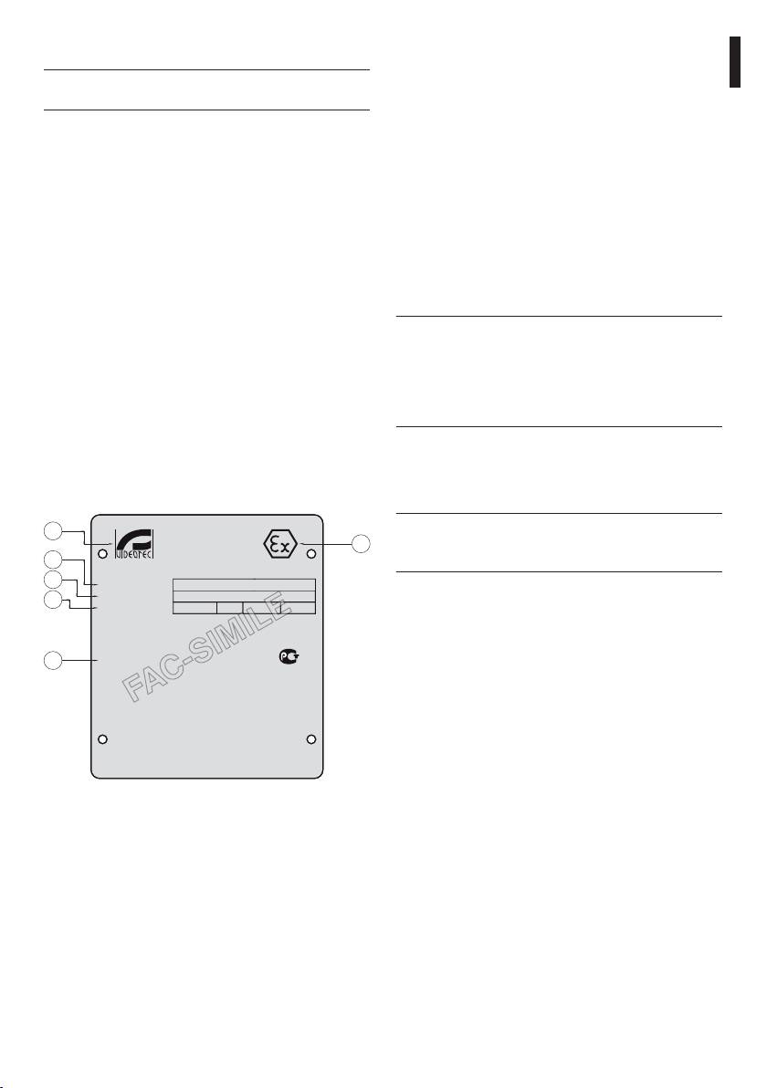
Fig. 01
• EXDTRX3 / EXDTRX324 receiver
01. EX symbol
• 2 3/4" NPT IP66 IECEX-ATEX-GOST screws plugs
02. Manufacturer’s name and address
• Instructions manual
03. Model identification code
04. Serial number
05. Housing
• Power voltage (V)
• Absorbed current (A)
• Frequency (Hz)
• Housing consumption (W)
7
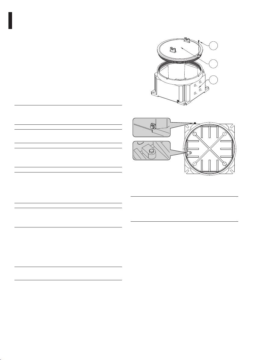
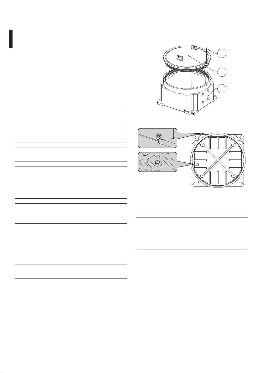
Security screw, to screw/unscrew, for the housing (01)
5.2 Safely disposing of
opening/closing. Body-cover (02) coupling threaded
packaging material
joint. As required, insert and screw the 3/4" NPT cable
glands and/or the 3/4" NPT blanking caps (03).
The packaging material can all be recycled. The
installer technician will be responsible for separating
the material for disposal, and in any case for
01
compliance with the legislation in force where the
device is to be used.
Bear in mind that if the material has to be returned
02
due to a fault, using the original packaging for its
transport is strongly recommended.
03
EN - English - Instructions manual
6 Assembling and
installing
Disconnect the power supply before
Fig. 02
g
proceeding with any operation, unless
indicated otherwise.
Only specialised personnel should be
h
allowed to assemble and install the device.
Use only cables suitable for the application
h
and that meet the standards required by
the installation.
The receiver is not supplied with already
h
mounted cable glands. Installers must
Fig. 03 Internal/external hearth-screws positions.
make sure they choose cable glands that
6.1.2 EXDTRX3 power supply
are in compliance with the EN/IEC 60079-14
standard.
The power supply of EXDTRX3 receiver
h
is 230Vac, 50/60Hz. The receiver must be
The unused cable gland holes must be
earthed using the internal and external
h
closed using NPT 3/4" plugs that are
earth screws (Fig. 03, page 8).
suitable for the housing marking.
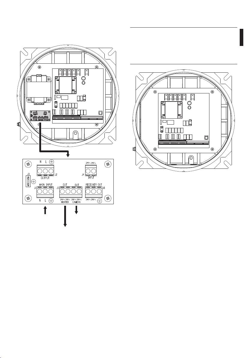
Power the receiver via terminal J1 (MAIN INPUT)
located on the support board. Connect the live phase
6.1 Installation
to terminal L, neutral to terminal N and earth to
terminal a.
6.1.1 Receiver opening
For a correct receiver opening and closing, refer to
the following drawings.
The receiver opening and closing must be
o
carry out in a non-explosive atmosphere.
8
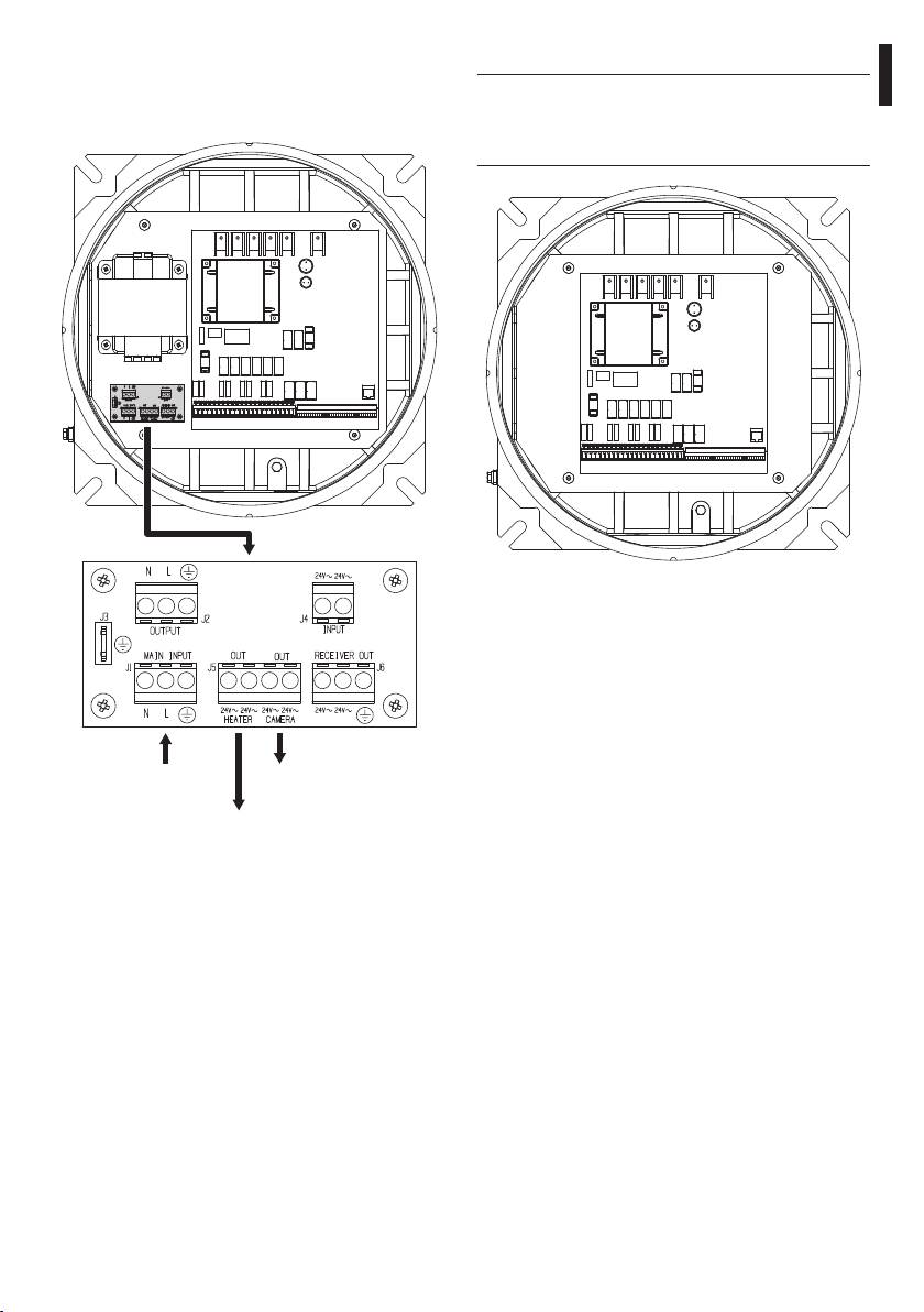
To power the camera use terminal J5, in the part
6.1.3 EXDTRX324 power supply
corresponding to CAMERA OUT (24Vac).
The power supply of EXDTRX324 receiver
To power the housing heater use terminal J5, in the
h
is 24Vac, 50/60Hz. The receiver must be
EN - English - Instructions manual
part corresponding to HEATER OUT.
earthed using the internal and external
earth screws (Fig. 03, page 8).
Fig. 05
J1 - IN 230Vac
J5 - CAMERA
OUT 24Vac
J5 - HEATER
OUT 24Vac
Fig. 04
9
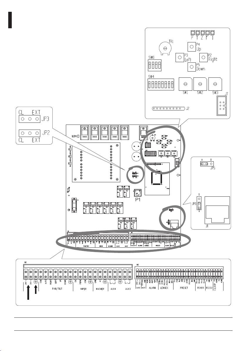
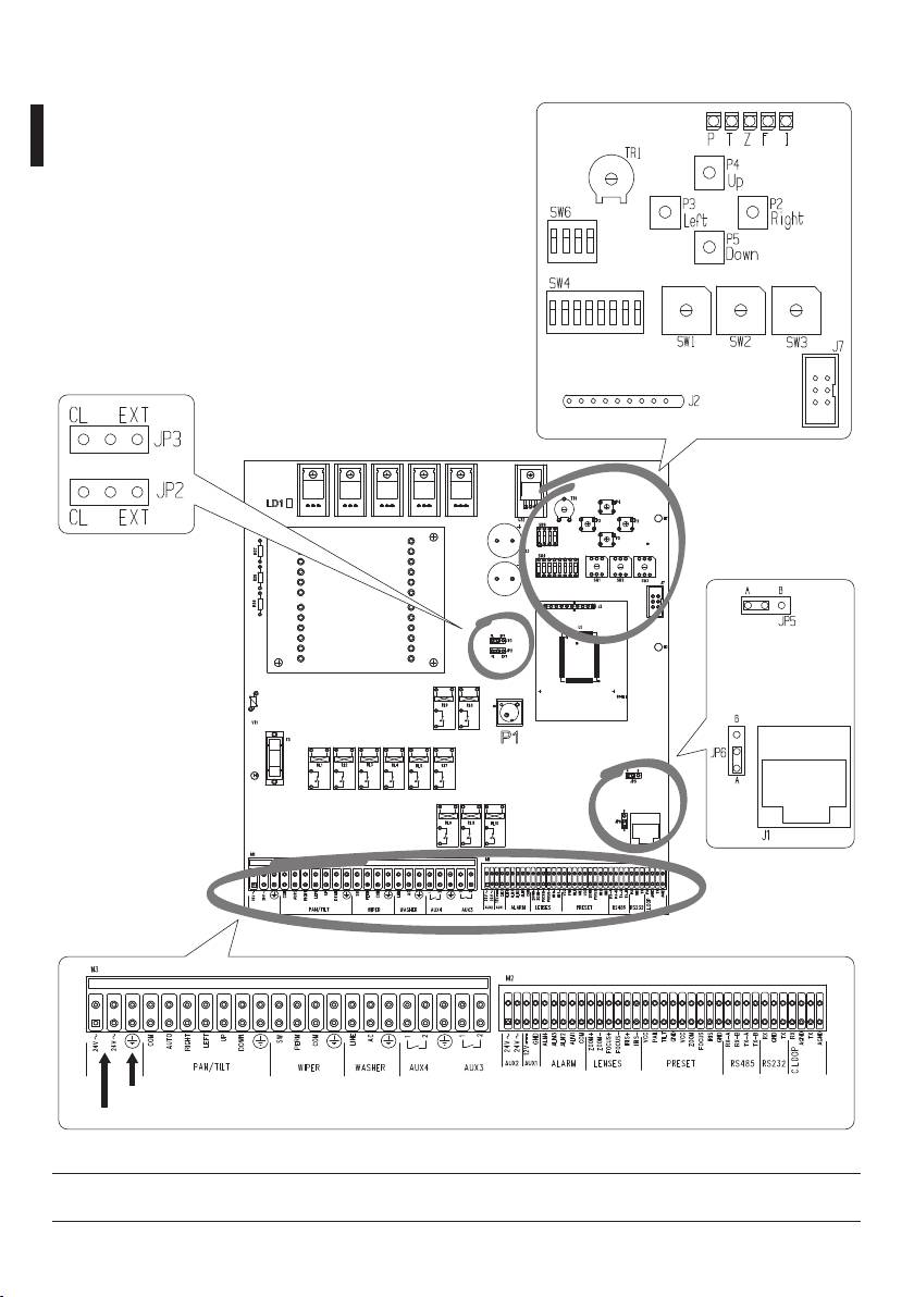
6.1.4 Configuration of dip switches and jumpers
In the following picture identify the dip switches and the configuration jumpers.
EN - English - Instructions manual
Ground
IN 24Vac
Fig. 06
Be sure the connector is earthed.
h
10

6.2 Configuration
6.2.2 Receiving mode
According to the communication type to set follow
The receiver configuration phase allows
the following settings:
EN - English - Instructions manual
j
to optimize its functioning according to
• Current Loop: JP2 and JP3 to CL position
the particular requirements of the plant.
The unit must be configured exclusively
• RS485: See below "6.2.3 Setting of RS485 line load",
during the installation phase and by an
page 11
installer. We recommend proceeding
• RS232: No setting needed
with the configuration of the parameters
6.2.3 Setting of RS485 line load
in a systematic way in order to avoid
installation troubles.
• Jumpers: JP5 and JP6
• JP5 in A position: Load connected in RS485 mode
The settings that must be configured the setup phase
• JP5 in B position: Load disconnected in RS485
are the following:
mode
• Identification number of the receiver;
• JP6 in A position: Load connected in RS485 mode
• Receiving mode setup;
• JP6 in B position: Load disconnected in RS485
• Type of lenses used;
mode
• Communication speed and protocol;
6.2.4 Type of lenses used
• AUX3 / AUX4 auxiliary devices;
An inaccurate setup of this parameters can
• Connection with the control unit;
g
cause damages to the lenses!
• Control voltage of lenses;
• Connection of the positioning device and the
The EXDTRX3 / EXDTRX324receiver can control both
lenses cables;
polarity inversion lenses and common wire lenses. In
case of common wire lenses connect the common
• Alarms setting;
wire to FOCUS-.
• Test of the receiver active functions (for PRESET
operations).
6.2.5 Auxiliary contacts
The receiver has 4 auxiliary contacts:
6.2.1 Receiver identification number
• AUX1: 12Vdc, 350mA
setting
• AUX2: 24Vac, 180mA
Configure the SW1, SW2 and SW3 rotative switches
according to the address to assign to the receiver as
The following are clean contacts:
follows:
• AUX3: 24Vac, 1A
• SW1: Hundred
• AUX4: 24Vac, 1A
• SW2: Ten
• SW3: Unit
Examples:
• Receiver address n. 359:
Set SW1 to 3, SW2 to 5 and SW3 to 9
• Receiver address n. 27:
Set SW1 to 0, SW2 to 2 and SW3 to 7
• Receiver address n. 4:
Set SW1 to 0, SW2 to 0 and SW3 to 4
11
6.2.6 Communication speed protocol
6.2.8 Connection with the control unit
setup
The RJ11 connector (J1 in the Fig. 06, page 10)
supplied to the circuit enables the reception and
An inaccurate protocol or communication
the transmission of digital data in RS232 or RS485
h
speed selection can cause damages to the
allowing a rapid connection of several units in case
receiver!
of test runs or for the connection of conversion
interfaces available on the market (RS232-optical
Used in digital transmission systems the EXDTRX3 /
fiber, etc.).
EXDTRX324 receiver can communicate with a speed
varying from 300 to 38400 baud, depending on the
The final connection must be in RS485 mode with
selected protocol.
DCJ, DCT and DCTEL keyboards. This mode allows to
reach a maximum distance of 1200m.
• Dip switch: Switches 1, 2 and 8 of SW4 e 1 of SW6
It is also possible to use control keyboards in Current
EN - English - Instructions manual
PROTOCOL
SW6 SW4
loop communication mode.
BAUD RATE
Dip 1 Dip 1 Dip 2 Dip 8
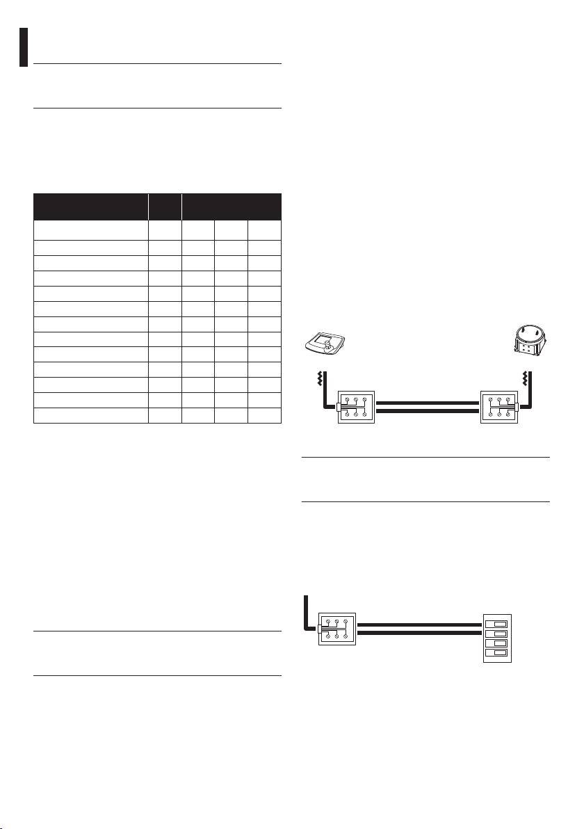
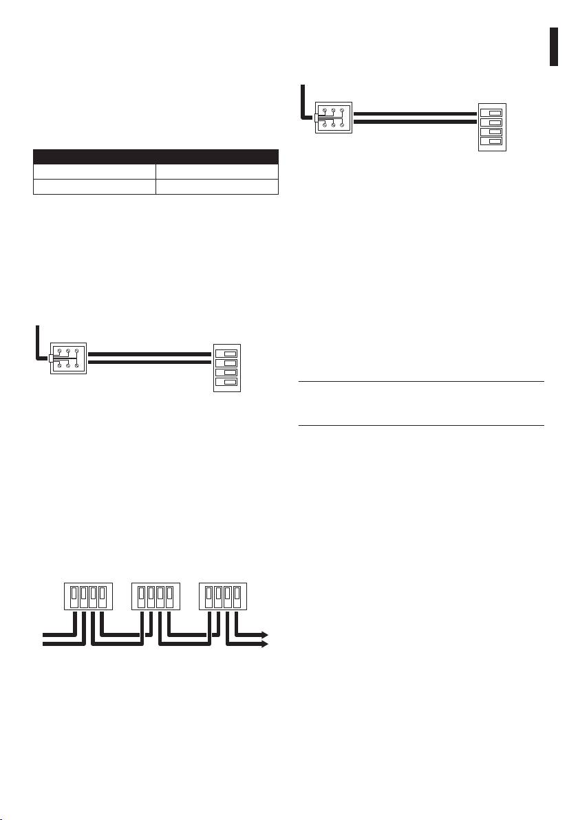
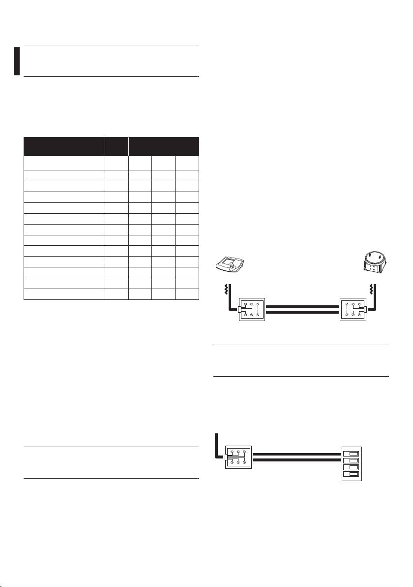
6.2.9 Connection with the RS485 line
The keyboards (DCJ, DCT and DCTEL) and the receiver
VIDEOTEC - 300 baud OFF ON OFF ON
can be directly connected using the telephone
VIDEOTEC - 1200 baud OFF OFF ON ON
cable supplied by the manufacturer, using the RJ11
VIDEOTEC - 9600 baud* OFF OFF OFF ON
(J1 in the Fig. 06, page 10) connector present in
VIDEOTEC - 19200 baud OFF ON ON ON
the circuit, as illustrated in the reference diagram
MACRO - 1200 baud OFF OFF ON OFF
hereunder.
MACRO - 9600 baud OFF OFF OFF OFF
MACRO - 19200 baud OFF ON ON OFF
MACRO - 38400 baud OFF ON OFF OFF
J1DCT
PELCO D - 2400 baud ON OFF OFF **
PELCO D - 4800 baud ON ON OFF **
White
Blue
PELCO D - 9600 baud ON OFF ON **
PELCO D - 19200 baud ON ON ON **
Yellow
Black
Tab. 01 * Default setup.
Fig. 07 Communication mode RS485, max distance 1200m.
** Switch setting is indifferent; ON or OFF.
The receiver has the load inserted in
6.2.7 AUX3 / AUX4 auxiliary devices
j
reception and is connected to line A or B on
setting
the keyboard with the load inserted.
It is possible to set the functioning of the AUX3 /AUX4
auxiliary devices by setting dip 6 of switch SW4:
On the receiver side it is also possible to make a
simpler connection to terminals RX-485A and RX-
• Dip 6 of SW4 set to the OFF (default) position:
485B as in the following scheme.
The operator has to press the control key in order
to activate the auxiliary device and then to press it
To RJ11
again in order to deactivate it.
keyboard
Receiver
connector
clamps
• Dip 6 of SW4 set to the ON position: The auxiliary
device remain activated as long as the operator
RS485
TX 485A (White)
keeps pressing the relevant control key.
RX-A
RX-B
AUX4 can be activated also on alarm
TX 485B (Yellow)
TX-A
j
contact ("6.2.20 Operation mode of AUX4",
TX-B
page 17).
Fig. 08
12
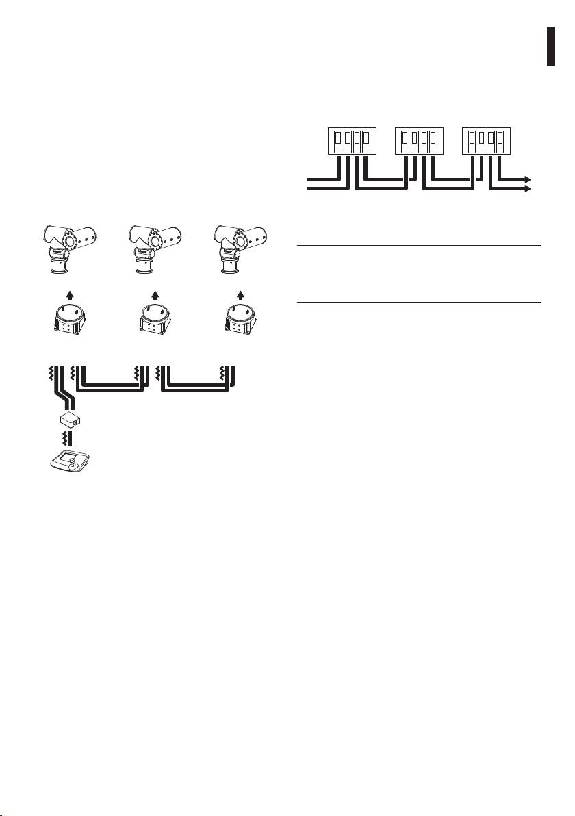
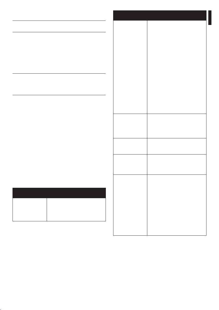
6.2.10 Connecting more than one receiver
Terminals RX-485A and RX-485B which have the load
inserted, should be connected to terminals TX-485A
in cascade (point-to-point connection)
and TX-485B respectively of the preceding unit,
The receivers are able to regenerate the received
EN - English - Instructions manual
which also have the load inserted:
signal internally and retransmit it along a new
communication line to the subsequent receiver. Each
RS485
RS485
RS485
of the three sections of line (L1, L2, L3) is considered
independent, and connects only two devices
RX-A
RX-B
TX-A
TX-B
RX-A
RX-B
TX-A
TX-B
RX-A
RX-B
TX-A
TX-B
point-to-point, each with inserted load, over a
maximum distance of 1200m. The distance between
the keyboard and receiver D can therefore be up
to 3600m (1200m between keyboard and receiver
B, 1200m between receiver B and receiver C, and a
further 1200m between receiver C and receiver D, for
From previous
To next
a total of 3600m).
receiver
receiver
Fig. 10
For the connection in question (point-
j
to-point) faulty operation of one of the
receivers will switch off all the devices in
EXPT
EXPT EXPT
cascade.
C DB
6.2.11 More than one receiver per line,
connection with twisted pair cable
EXDTRX3
EXDTRX3
EXDTRX3
EXDTRX324
EXDTRX324
EXDTRX324
(multipoint connection)
All receivers connected to the same line should use
the same communication protocol RS485.
L1
L2
L3
For each of the lines the following remarks are valid:
A
• Only one of the keyboards (that at one end of the
line) has the load inserted;
• Only one of the receivers (at the other end of the
line) has the load inserted;
• The total length of the line should not exceed
DCT
1200m.
Fig. 09
The connection between the keyboard and the first
receiver must be carried out as illustrated in the
diagram in Fig. 08, page 12.
13
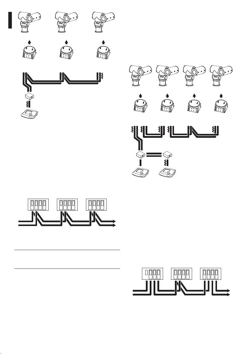
6.2.12 Mixed configurations (point-to-
point / multi-point)
This is a combination of the two previous connection
modes and, depending on the combination chosen,
EXPT EXPTEXPT
allows the user to exploit the advantages of the
two types of connection to the utmost, significantly
A2 A3A1
reducing the probability of faulty operation.
The following is an example of mixed connection:
EXDTRX3
EXDTRX3
EXDTRX3
EXDTRX324
EXDTRX324
EXDTRX324
EN - English - Instructions manual
EXPTEXPT
EXPT EXPT
A
R2R1
R3 R4
EXDTRX3
EXDTRX3
EXDTRX3
EXDTRX3
DCT
EXDTRX324
EXDTRX324
EXDTRX324
EXDTRX324
Fig. 11
L1
Line A on keyboard has been used for
L4L3L2
communication with telemetry. The ends (Keyboard
- Receiver A3) should have the termination resistor
K2
K1
inserted. Receivers A1, A2 should not have the
L1
termination resistor inserted. The maximum line
length, from end to end (from the keyboard to
receiver A3), is 1200 meters.
DCTDCT
RS485
RS485
RS485
Fig. 13
RX-A
RX-B
TX-A
TX-B
RX-A
RX-B
TX-A
TX-B
RX-A
RX-B
TX-A
TX-B
In the example shown, if receiver R3 jams (multi-
point connection in line L3) it will not cause faulty
operation in receiver R4.
R3 is not at the ends of line L3and
it is not therefore necessary to terminate it.
From previous
To next
If receiver R2 jams, since it is the "generator" of line
receiver
receiver
L3, all receivers connected to it in cascade (R3 and R4)
Fig. 12
will not receive the commands.
For the connection (multi-point) faulty
RS485
RS485
RS485
j
operation of one of the receivers will not
influence the other receivers.
RX-A
RX-B
TX-A
TX-B
RX-A
RX-B
TX-A
TX-B
RX-A
RX-B
TX-A
TX-B
From previous
To next
receiver
receiver
Fig. 14
14
6.2.13 Connection with the Current
6.2.14 Connection with the RS232 line
Loop line
Al connettore
The various devices can be connected directly using
RJ11 della
Morsetti sul
EN - English - Instructions manual
tastiera
ricevitore
the telephone cable supplied by the manufacturer.
RS232
For normal connections in the field, refer to the
TX RS232 (Nero)
connections made using the shunt boxes RJ, supplied
RX
GND
by the manufacturer, following the reference tables
GND RS232 (Verde)
given below:
KEYBOARD EXDTRX3, EXDTRX324
Fig. 17 Communication mode RS232, max distance 15m.
TX CL Yellow Terminal RX CL
GND CL Red Terminal AGND
6.2.15 Adjusting the voltage of the
optics controls
Tab. 02 Current Loop Communication Mode, max. distance
1500 meters from receiver, Jumper JP2 and JP3 in
• Connect the power supply cable and power the
position CL.
unit (LD1 lit up);
From the receiver side the connection should be
• Insert a load between terminals FOCUS NEAR and
made to terminals RXCL and AGND according to the
FOCUS FAR to absorb at least 10 mA (use a resistor
following scheme:
from 100 to 1000 ohm);
To RJ11
• Position the tester prods on terminals FOCUS NEAR
keyboard
Receiver
and FOCUS FAR;
connector
clamps
• Keep one of the two FOCUS keys on the control
CURRENT LOOP
unit pressed down;
TX CL (Yellow)
RX
• Adjust the control voltage of the optics by
AGND
TX
adjusting trimmer TR1 ( default 12Vdc).
GND CL (Red)
AGND
Don’t make unloaded voltage regulation
h
(without inserting the load) otherwise the
Fig. 15
adjustment will be incorrect.
• If the receiver is connected in cascade to another
EXDTRX3 / EXDTRX324 unit, the reception mode
should be set in Current Loop with jumpers JP2
and JP3 in position CL.
• Terminals RX CL and AGND should be connected
to the preceding unit terminals TX CL and AGND
respectively as in the following scheme:
Current
Current
Current
Loop
Loop
Loop
RX
AGND
TX
AGND
RX
AGND
TX
AGND
RX
AGND
TX
AGND
From previous
To next
receiver
receiver
Fig. 16
15

6.2.16 Connecting the pan & tilt and
6.2.18 Testing the receiver
optics cables
After having connected the positioning device and
the lens cables, to check the correct working of the
Before carrying out the following
devices, it’s possible to perform an automatic test
g
operations make sure that the pan & tilt
which will show the allowed functions:
control voltage and the setting for optics
type are correct.
Since during this phase the positioning
h
devices makes automatically some
• Disconnect the power supply to the unit;
predetermined movements. Do not lean
• Make the connections with the optics and pan &
on during the test and do not obstruct its
tilt;
trajectory.
• Reconnect the power supply to the unit.
Proceed according to the following indications:
EN - English - Instructions manual
For optics and pan & tilt with PRESET
• Power the receiver on;
h
functions (PAN, TILT, ZOOM, FOCUS and
• Identify the Up arrow-switch (P4 switch) and the
IRIS, VCC and GND), the maximum length
reset switch (P1 switch);
of the preset cables should not exceed 5
• Keep pushing the Up switch and press the reset
metres, otherwise positioning on the stored
switch;
positions will be incorrect.
• Release the reset switch (keep pushing the Up
6.2.17 Setting the receiver for PRESET
switch): the automatic test starts;
functions
• After the starting of the test, release the Up switch.
The receiver has integrated preset functions (for
The receiver starts up one function at a time, for
pan&tilt and the optics).
about 3 seconds:
With PELCO D and MACRO protocols, it is possible to
• Pan: Left-right (Led P)
store up to 40 positions, which can be recalled using
• Tilt: Low-high (Led T)
the Scan and Patrol functions on the keyboard.
• Zoom: Wide-tele (Led Z)
The receiver is able to make a test to automatically
• Focus: Far-near (Led F)
detect which preset functions are present and
configuring the device is therefore a simple
• Iris: Close-open (Led I)
operation. However, it is necessary to take certain
The result of the test is shown from the 5 control leds
precautions:
P, T, Z, F, I (placed near the arrow-switches, Fig. 06,
• Before making the receiver test (to determine
page 10) at the end of the of the movement of the
which preset functions are active), make sure
Pan&Tilt and lens:
the cables for pan&tilt and the optics have been
• Led switched on and fixed: The relevant function
connected correctly;
(PAN= P, TILT= T, ZOOM= Z, FOCUS= F, IRIS= I)
• For the preset cables (PAN, TILT, ZOOM, FOCUS,
works correctly;
IRIS, VCC and GND) use cables with a maximum
• Led switched on and blinking: The relevant
length of 5m.
function doesn’t work or is not present and cannot
be used for preset/scan/patrol functions.
After some seconds from the end of the test the
receiver automatically starts working.
A blinking of at least one of the leds at the
h
end of the test (provided that this function
is included) indicates a malfunction to
which you must find a remedy before the
receiver starts working.
16

6.2.19 Use of the alarm contacts
6.2.22 PELCO D commands recognised
The 4 alarm contacts of EXDTRX3 / EXDTRX324
by the receiver
receiver are associated with the first four preset
As well as recognising standard PELCO D commands
EN - English - Instructions manual
positions; as soon as the alarm is activated,
relating to joystick and lens movements, the receiver
the positioning device and the lens adopt the
is able to recognise and execute the following
corresponding preset position; the last alarm
extended PELCO D commands.
activated takes always priority. The EXDTRX3 /
EXDTRX3 /
EXDTRX324 can also receive an alarm command
PELCO D
EXDTRX324
NOTE
even through theDCJ, DCT and DCTEL control
COMMAND
COMMAND
keyboard (which in turn receives it from the SM164B
Set Auxiliary Aux ON Recognise values
and SM328B matrix); in such case the positioning
between 1 and 4
device and the lens move themselves into the preset
Clear Auxiliary Aux OFF Recognise values
position n°1.
between 1 and 4
In order to use the alarm contacts it is necessary to
Set Pattern Start Autopan Toggle --
set the SW4 according to the following instructions:
Run Pattern Patrol Toggle --
• Dip 3 of SW4 set to the ON position: The alarm
contacts are activated;
Remote Reset Receiver Reset --
• Dip 3 of SW4 set to the OFF position: The alarm
Go To Preset
Scan Recognise values
contacts are deactivated;
“1÷40”
between 1 and 40
Set Preset “1÷40” Preset position Recognise values
• Dip 4 of SW4 set to the ON position: The alarm
between 1 and 40
contacts are normally open;
Clear Preset
Reset of Preset
Recognise values
• Dip 3 of SW4 set to the OFF position: The alarm
“1÷40”
Single Position
between 1 and 40
contacts are normally closed.
Set Preset “41” Starting Patrol
--
parameters
6.2.20 Operation mode of AUX4
acquisition
• Switches: Dip 5 of SW4
(see example**)
Settings:
Set Preset “…” Patrol “Position
Recognise values
• Dip 5 of SW4 OFF: Normal operation;
From”
between 1 and 40
Set Preset “…” Patrol “ Position
Recognise values
• Dip 5 of SW4 ON: AUX4 is activated on alarm and
To”
between 1 and 40
deactivated when the alarm signal stops.
Set Preset “…” Patrol “Pause” Recognise values
6.2.21 Local keys for P&T motor
between 1 and 99
movement
Set Preset “42” Patrol Start --
The receiver has 4 local arrow-keys (on board) for
Set Preset “43” Patrol Stop --
the P&T motor movement in the 4 directions (Up,
Set Preset “44” Washer-Wiper* --
Down, Left, Right, Fig. 06, page 10). These keys are
very useful during P&T motor installation in order
Set Preset “55”
Reset of all Preset
The two
to control the position of limit switches and/or the
positions
commands
Set Preset “66”
must be given in
right setting of the P&T motor. The arrow-keys have
sequence
total priority and, when pressed, they deactivate at
the moment the receiver remote use (by keyboards).
Tab. 03 * With the following timing: in the first second, only
When the arrow-keys are released the receiver
the Washer is activated, in the next two seconds the
functions are fully restored.
Washer and Wiper are activated simultaneously, and
then during the last second the Washer is switched off
The combination of Up key and reset key is used to
and just the Wiper is left on.
carry out the auto-test ("6.2.18 Testing the receiver",
page 16).
17

6.2.22.1 Example of Patrol sequence
6.2.24 Dip switch SW6 and SW4
programming.
configuration table
If you want to set up a Patrol sequence that starts
SW6
from Preset position 19, ends at Preset position 33
Dip Position Function
and stops for one minute at every position reached:
1 ON PELCO D protocol
: Enables parameter insertion;
1 OFF VIDEOTEC or MACRO
: Start Patrol at position 19;
protocols (setting the dip 8
: End Patrol at position 33;
of SW4)
2, 3, 4 Indifferent No function
: Pause of 60 seconds at every position
reached;
SW4
: Start of sequence;
EN - English - Instructions manual
Dip Position Function
: End of sequence.
1, 2 OFF, OFF 9600 baud* (VIDEOTEC and
6.2.23 Switching on and switching off
MACRO), 2400 PELCO D
Before connecting the unit:
1, 2 ON, OFF 300 baud VIDEOTEC, 38400
baud MACRO, 4800 baud
• Make sure that the goods supplied correspond
PELCO D
to the required specifications by controlling the
1, 2 OFF, ON 1200 baud (VIDEOTEC and
rating plates ("4.2 Product markings", page 7);
MACRO), 9600 baud PELCO D
• Make sure that the fuses of the EXDTRX3 /
1, 2 ON, ON 19200 baud (VIDEOTEC,
EXDTRX324 receiver are not damaged;
MACRO and PELCO D)
• Make sure that the receiver and the other
3 OFF Unused alarms*
components of the plant are closed in order to
3 ON Used alarms
avoid the direct contact with live elements;
4 OFF N.C. alarms*
• Make sure that all parts are accurately and firmly
4 ON N.O. alarms
fixed;
• The power cords must not hamper the normal
5 OFF -
operations of the installer and the movement of
5 ON Alarms on Aux4
the positioning device;
6 OFF -
• Make sure that all power sources and the
connecting cables are able to bear the system
6 ON To release Aux3 and Aux4
consumption.
7 OFF -
8 ON** VIDEOTEC standard
protocol****
8 OFF*** MACRO protocol **** ((DCIR,
DCJ, DCT and DCTEL)
Tab. 04 * Default settings.
** Compatible with keyboards DCIR, DCJ, DCT and
DCTEL with VIDEOTEC standard protocol.
*** Compatible with keyboards DCIR, DCJ, DCT and
DCTEL with MACRO protocol.
**** Selectable only if the dip 1 of SW6 is in OFF
position.
18
POSSIBLE CAUSES AND
7 Maintaining and cleaning
PROBLEM
SOLUTIONS
The receiver does not require special
Led LD1 is on but
Wrong configuration of the
EN - English - Instructions manual
the instruction are
reception.
j
maintenance operations.
not executed.
In case of RS485 mode, check if the
We recommend positioning the power cords and
load is inserted/not inserted with
the connecting cables such that they are not likely to
JP5 jumper. In case of Current Loop
mode, verify that the JP2 and JP3
hamper the operator.
jumper are on CL position.
Wrong connection.
8 Disposal of waste
Check the connecting cables.
materials
Wrong identification.
Check the identification number of
This symbol mark and recycle system
(SW1-SW2-SW3).
are applied only to EU countries and not
The unit is blocked.
n
applied to the countries in the other area of
Press the reset key P1 or turn off the
the world.
power supply.
Your product is designed and manufactured with
Wrong speed or protocol.
high quality materials and components which can be
Check the setting of dip 1, 2 and 8 of
recycled and reused.
SW4 and dip 1 of SW6.
This symbol means that electrical and electronic
The positioning
Wrong power supplied to the
device does not
positioning device.
equipment, at their end-of-life, should be disposed of
work.
separately from your household waste.
Make sure that the supply voltage of
the positioning device corresponds
Please dispose of this equipment at your local
to the one supplied by the receiver.
Community waste collection or Recycling centre.
The lens does not
Wrong lens voltage.
In the European Union there are separate collection
work.
Check the adjustment of the TR1
systems for used electrical and electronic products.
trimmer.
The alarms does not
Wrong configuration of alarms
9 Troubleshooting
work.
dip.
Control the setting of dip 3, 4 and
Although the receiver is characterized by a great ease
5 of SW4.
of use, sometimes troubles may occur, especially
In a cascade
Wrong connection.
during the installation and configuration phases or
connection, the
using the unit.
Check the connecting cables.
units which follow
Wrong configuration of the
POSSIBLE CAUSES AND
do not receive the
PROBLEM
reception.
SOLUTIONS
user’s commands.
In case of RS485 mode, check if the
Led LD1 is off. No power supplied to the unit.
load is inserted/not inserted with
Check the power cable.
JP6 jumper. In case of Current Loop
The fuse is blown.
mode, verify that the JP2 and JP3
jumper are on CL position.
Replace the F5 fuse (6.3A F 250V).
Dip switch wrong configuration.
Control the address setting of the
non-functioning units.
Tab. 05
19

10 Technical specifications
10.5 Protocol
VIDEOTEC (300, 1200, 9600, 19200 Baudrate)
10.1 General
MACRO (1200, 9600, 19200, 38400 Baudrate)
Built in aluminium alloy
PELCO D (2400, 4800, 9600, 19200 Baudrate)
Neoprene gaskets
10.6 Accessories
Stainless steel screws
Epoxypolyester powder painting, RAL7032colour
OCTEX3/4C Cable gland with gasket EX
3/4" NPT unarmoured cable
Supplied with instruction manual
IECEX-ATEX-GOST
10.2 Mechanical
OCTEXA3/4C Cable gland with gasket EX
3/4" NPT armoured cable
External Dimensions: 410x410x296mm
IECEX-ATEX-GOST
EN - English - Instructions manual
(16.1x16.1x11.6in)
OCTEXB3/4C Barrier cable gland EX 3/4"
Internal Dimensions: 353x353x206mm (13.8x13.8x8.1in)
NPT, anarmoured cable
Unit Weight: EXDTRX3 32kg / 70.5lb, EXDTRX324 29kg /
IECEX-ATEX-GOST
63.9lb
OCTEXBA3/4C Cable gland with gasket EX
3/4" NPT armoured cable
10.3 Electrical
IECEX-ATEX-GOST
OCTEX3/4 Cable gland with gasket EX
Power Supply
3/4" NPT unarmoured cable
- IN 230Vac, 50/60Hz, 40W max
ATEX
- IN 24Vac, 50/60Hz, 40W max
OCTEXA3/4 Cable gland with gasket EX
Max switching power: 100W
3/4" NPT armoured cable
ATEX
Power supplied to the positioning device: IN 24Vac,
50/60Hz
OEXPLUG3/4 Plug EX 3/4" NPT IECEX-
ATEX-GOST
Power supplied to glass protection device: IN 24Vac
Power supplied to the lens: IN 3-12Vdc (max 100mA)
10.7 Environment
999 selectable addresses through Dip Switch
Indoor / Outdoor
Ability of using both polarity inversion lenses and
common wire lenses
Operating temperature: 0°C / +50°C (+32°F / +122°F)
LED indicating power supplied to the unit
10.8 Compliance to
LED indicating active function
ATEX, directive 94/9/CE
EEPROM for the storage of active options
II: Group (surface device, no mining)
16 bit microcontroller with re-programmable Flash
memory
2: Category (elevated protection degree, the devices in
this category can be installed in zone 1 and 21 and in
PRESET / SCAN / PATROL functions with an automatic
zone 2 and 22)
recognition of the existing functions
GD: Atmosphere type (gases and dusts)
Ability to memorize up to 14 PRESET functions (P&T
motor, lens).Up to 40 positions if combined with DCJ and
Ex d: explosion-proof housing for potentially explosive
DCT keyboards
environments
4 alarm contacts set as N.O. or N.C.
IIC: gases group
T6: temperature classification for gases
10.4 Communications
Ex tD A21: dust ignition protection, zones type 21-22
Serial input selectable between RS232 / Current Loop /
IP66: IP protection degree
RS485
T85°C: Maximum surface temperature for dusts
Selectable communication speed (38400 / 19200 / 9600
EXDTRX3 - EXDTRX324
/1200 / 300 Baudrate)
ATEX b II 2 GD Exd IIC T6 Ex tD A21 IP66 T85°C
RS232, RS485 and Current Loop repeater for in-line
configuration
c 0722: notify number from competent body
GOST-R 1ExdIICT6 и DIP A21 T
T85°C
A
20
10.9 Cable glands
CABLE GLANDS SELECTION TABLE
EN - English - Instructions manual
Zone - Gas Cable gland
Certification Operating
Cable Cable glands
External
Diameter
type
temperature
part code
diameter
under
(mm)
armour
(mm)
IIC
Barrier IECEX / ATEX /
-60 / +80°C
Not armored OCTEXB3/4C 13 - 20.2 -
Zone 1 or
GOST
-76 / 176°F
Zone 2
IIB
Armored OCTEXBA3/4C 16.9 - 26 -
Zone 1
IIB o IIA
With gasket IECEX / ATEX /
-60 / +100°C
Not armored OCTEX3/4C 13 - 20.2 -
Zone 2
GOST
-76 / 212°F
Armored OCTEXA3/4C 16.9 - 26 11.1 - 19.7
ATEX -20 / +80°C
Not armored OCTEX3/4 14 - 17 -
-4 / 176°F
Armored OCTEXA3/4 18 - 23 14 - 17
Tab. 06
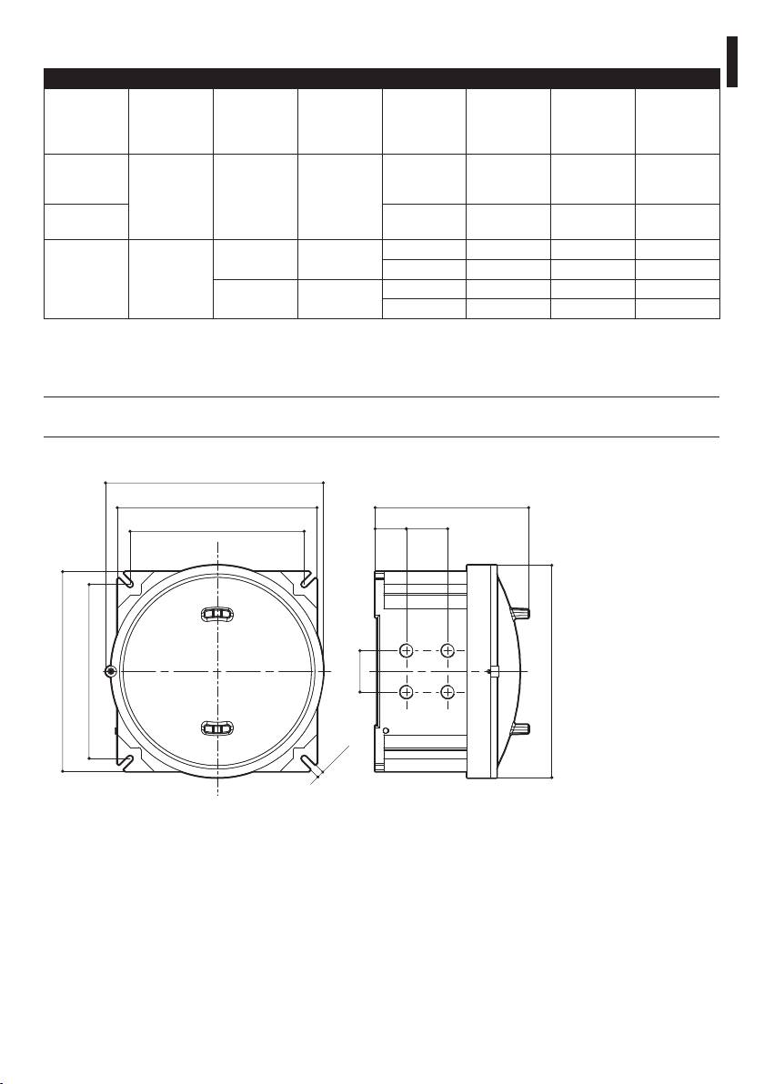
11 Technical drawings
The values are in millimeters.
j
421
385
296
= 336 =
60 80
385
80
Ø 410
= 336 =
14
Fig. 18 EXDTRX3, EXDTRX324
21
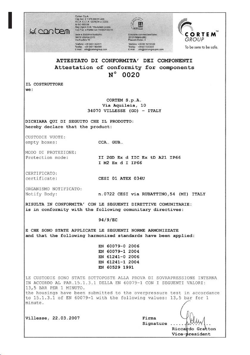
12 Appendix A - CORTEM declaration
EN - English - Instructions manual
22
EN - English - Instructions manual
23

VIDEOTEC S.p.A.
www.videotec.com
Printed in Italy
MNVCEX324_1149_EN
EXDTRX3 - EXDTRX324
Ricevitore di telemetria antideflagranti
IT
Italiano - Manuale di istruzioni
ITALIANO


Sommario
ITALIANO
1 Informazioni sul presente manuale ............................................................................ 5
1.1 Convenzioni tipografiche .................................................................................................................................... 5
IT - Italiano - Manuale di istruzioni
2 Note sul copyright e informazioni sui marchi commerciali ...................................... 5
3 Norme di sicurezza ....................................................................................................... 5
4 Identificazione .............................................................................................................. 6
4.1 Descrizione e designazione del prodotto ..................................................................................................... 6
4.2 Marcatura del prodotto ........................................................................................................................................ 7
5 Preparazione del prodotto per l'utilizzo .................................................................... 7
5.1 Contenuto e disimballaggio ............................................................................................................................... 7
5.2 Smaltimento in sicurezza dei materiali di imballaggio ............................................................................. 8
6 Assemblaggio e installazione ...................................................................................... 8
6.1 Installazione ............................................................................................................................................................. 8
6.1.1 Apertura del ricevitore ......................................................................................................................................................... 8
6.1.2 Tensione d’alimentazione EXDTRX3 ................................................................................................................................ 8
6.1.3 Tensione d’alimentazione EXDTRX324 ........................................................................................................................... 9
6.1.4 Dip switch e jumper di configurazione ........................................................................................................................10
6.2 Configurazione ...................................................................................................................................................... 11
6.2.1 Impostazione del numero di identificazione del ricevitore .................................................................................. 11
6.2.2 Modalità di comunicazione .............................................................................................................................................. 11
6.2.3 Inserimento del carico nella linea RS485 ..................................................................................................................... 11
6.2.4 Tipo di ottiche controllate ................................................................................................................................................. 11
6.2.5 Contatti ausiliari .................................................................................................................................................................... 11
6.2.6 Impostazione del protocollo e della velocità di comunicazione ........................................................................12
6.2.7 Impostazione degli ausiliari AUX3 / AUX4 ..................................................................................................................12
6.2.8 Collegamento con l’unità di comando ......................................................................................................................... 12
6.2.9 Collegamento con la linea RS485 ................................................................................................................................... 12
6.2.10 Collegamento di più ricevitori in cascata (collegamento punto-punto) ....................................................... 13
6.2.11 Più ricevitori per linea, collegamento con doppino twistato (collegamento multipunto) ..................... 13
6.2.12 Configurazioni miste (punto-punto / multipunto) ................................................................................................14
6.2.13 Collegamento con la linea Current Loop ..................................................................................................................15
6.2.14 Collegamento con la linea RS232 ................................................................................................................................15
6.2.15 Regolazione della tensione di controllo dell’ottica ...............................................................................................15
6.2.16 Collegamento dei cavi del brandeggio e delle ottiche ........................................................................................16
6.2.17 Settaggio del ricevitore per le funzioni di PRESET .................................................................................................16
6.2.18 Test del ricevitore ............................................................................................................................................................... 16
6.2.19 Uso dei contatti di allarme .............................................................................................................................................17
6.2.20 Modalità di funzionamento di AUX4 ..........................................................................................................................17
6.2.21 Tasti locali movimento brandeggio ............................................................................................................................17
6.2.22 Comandi PELCO D riconosciuti da ricevitore ........................................................................................................... 17
6.2.22.1 Esempio di programmazione di una sequenza di Patrol .......................................................................................................... 18
6.2.23 Accensione e spegnimento............................................................................................................................................18
6.2.24 Tabelle di configurazione dei dip switch SW6 e SW4 ...........................................................................................18
7 Manutenzione e pulizia.............................................................................................. 19
3

8 Smaltimento dei rifiuti ...............................................................................................19
9 Troubleshooting ......................................................................................................... 19
10 Dati tecnici ................................................................................................................20
10.1 Generale ................................................................................................................................................................ 20
10.2 Meccanica ............................................................................................................................................................. 20
10.3 Elettrico .................................................................................................................................................................20
10.4 Comunicazioni ....................................................................................................................................................20
10.5 Protocolli ............................................................................................................................................................... 20
10.6 Accessori ...............................................................................................................................................................20
10.7 Ambiente ..............................................................................................................................................................20
10.8 Conformità ...........................................................................................................................................................20
10.9 Pressacavi ..............................................................................................................................................................21
IT - Italiano - Manuale di istruzioni
11 Disegni tecnici .......................................................................................................... 21
12 Appendice A - Dichiarazione CORTEM ....................................................................22
4

1 Informazioni sul presente
3 Norme di sicurezza
manuale
Il produttore declina ogni responsabilità
h
per eventuali danni derivanti da un
Prima di installare e utilizzare questa unità, leggere
uso improprio delle apparecchiature
attentamente questo manuale. Conservare questo
menzionate in questo manuale. Si
IT - Italiano - Manuale di istruzioni
manuale a portata di mano come riferimento futuro.
riserva inoltre il diritto di modificarne il
contenuto senza preavviso. Ogni cura è
1.1 Convenzioni tipografiche
stata posta nella raccolta e nella verifica
PERICOLO!
della documentazione contenuta in questo
g
Pericolosità elevata.
manuale, tuttavia il produttore non può
Rischio di scosse elettriche. Togliere
assumersi alcuna responsabilità derivante
l'alimentazione prima di procedere con le
dall'utilizzo della stessa. Lo stesso dicasi
operazioni, salvo diversa indicazione.
per ogni persona o società coinvolta nella
creazione e nella produzione di questo
manuale.
PERICOLO!
o
Pericolo di esplosione.
• Assicurarsi che tutti i dispositivi siano adatti per
Leggere attentamente per evitare pericoli
l’applicazione e l’ambiente per cui sono stati
di esplosione.
progettati.
• Assicurarsi che i dispositivi collegati siano
ATTENZIONE!
completamente compatibili e adatti all’uso.
h
Pericolosità media.
L'operazione è molto importante per il
• Controllare che le temperature di esercizio siano
corretto funzionamento del sistema. Si
compatibili con i dispositivi.
prega di leggere attentamente la procedura
• Accertarsi di installare i dispositivi in maniera
indicata e di eseguirla secondo le modalità
tale da garantire la sicurezza dell’impianto e del
previste.
personale addetto all’installazione.
• Accertarsi che il dispositivo sia fissato in maniera
INFO
solida ed affidabile.
j
Descrizione delle caratteristiche del
• Dato che la scelta della superficie di montaggio
sistema.
è a cura dell’utente non si forniscono viti per il
Si consiglia di leggere attentamente per
fissaggio sicuro del dispositivo alla superficie. È
comprendere le fasi successive.
responsabilità dell’installatore utilizzare viti adatte
allo scopo specifico richiesto.
2 Note sul copyright e
• L’installazione e la manutenzione del dispositivo
deve essere eseguita solo da personale tecnico
informazioni sui marchi
qualificato.
commerciali
• Utilizzare degli utensili adeguati. Degli utensili
specifici possono essere richiesti, per motivi
I nomi di prodotto o di aziende citati sono marchi
di installazione, in relazione al luogo in cui il
commerciali o marchi commerciali registrati
dispositivo viene installato.
appartenenti alle rispettive società.
• Assicurarsi che l’installazione soddisfi le specifiche
locali.
5

• Questo dispositivo deve essere installato fuori dalla
4 Identificazione
portata dell’utente o di chiunque ne possa entrare
a contatto casualmente.
4.1 Descrizione e designazione
• Prima di effettuare interventi tecnici
del prodotto
sull’apparecchio togliere l’alimentazione elettrica.
• Non utilizzare cavi di alimentazione con segni di
Ricevitore di telemetria in scatola antideflagrante
usura o invecchiamento.
per brandeggi serie EXPTC e EXPTD. Permette
l’installazione in una zona potenzialmente esplosiva.
• L’apparecchio deve essere aperto soltanto da
personale tecnico qualificato e in atmosfera non
EXDTRX3/EXDTRX324 permette il pieno controllo
esplosiva. La manomissione dell’apparecchio fa
delle funzione dei brandeggi antideflagranti, tra cui le
decadere i termini di garanzia.
funzioni di preset e patrol.
• Non permettere l’uso dell’apparecchio a bambini
Il ricevitore è verniciato a polveri di epossipoliestere,
o incapaci.
colore RAL7032, IP66.
• L’apparecchio si considera disattivato soltanto
La scatola antideflagrante presenta 4 fori per
quando l’alimentazione é disinserita e i cavi di
pressacavi 3/4" NPT.
IT - Italiano - Manuale di istruzioni
collegamento con altri dispositivi sono stati
La scelta del pressacavo deve essere fatta secondo
rimossi.
quanto previsto dalla norma EN/IEC 60079-14.
• Prima dell’alimentazione del dispositivo installare
Disponibile in 230Vac, EXDTRX3 e in 24Vac,
un dispositivo di protezione nell’impianto elettrico
EXDTRX324.
dell’edificio.
Si consiglia l'utilizzo di pressacavi
• Si raccomanda all’utente di non installare
j
VIDEOTEC o equivalenti (Tab. 06,
all’interno del dispositivo qualsiasi apparecchiatura
pagina 21).
che generi radiazioni pericolose.
• Per l’assistenza tecnica rivolgersi esclusivamente al
personale tecnico autorizzato.
• Conservare con cura il presente manuale; deve
essere a disposizione per eventuali consultazioni
nel luogo in cui viene eseguita l’installazione.
• Non effettuare per nessun motivo alterazioni o
collegamenti non previsti in questo manuale:
l’uso di apparecchi non idonei può portare a
gravi pericoli per la sicurezza del personale e
dell’impianto.
• Utilizzare solo parti di ricambio VIDEOTEC.
• Prima di procedere con l'installazione controllare
che il materiale fornito corrisponda alle specifiche
richieste esaminando le etichette di marcatura ("4.2
Marcatura del prodotto", pagina 7).
• Consultare e conservare con cura il manuale di
sicurezza della cassetta antideflagrante CORTEM.
6

06. Certificazione GOST-R:
4.2 Marcatura del prodotto
• Numero del certificato GOST-R
Sul ricevitore sono
• Classificazione del tipo di zona, metodo di
j
riportate 4 etichette.
protezione e classe di temperatura per le quali è
ammesso l’impiego di questo prodotto secondo
Etichetta posta sull’imballo:
gli STANDARD GOST-R
IT - Italiano - Manuale di istruzioni
• Codice di identificazione del modello;
Etichetta posta sulla scheda elettronica:
• Descrizione del prodotto;
• Codice di identificazione del modello;
• Grado IP;
• Grado IP;
• Tensione d’alimentazione (Volt);
• Tensione di alimentazione (Volt);
• Frequenza (Hertz);
• Frequenza (Hertz);
• Corrente max (Ampere);
• Corrente max (Ampere);
• Numero di serie del prodotto (codice a barre
• Numero di serie del prodotto.
Extended 3/9).
Prima dell’installazione controllare se
Etichetta posta sulla cassetta antideflagrante:
h
le caratteristiche di alimentazione e
• Codice della cassetta (CORTEM);
protezione del dispositivo corrispondono
• Tensione di alimentazione (Volt);
a quelle richieste. L’uso di apparecchi non
• Frequenza (Hertz);
idonei può portare a gravi pericoli per la
sicurezza del personale e dell’impianto.
• Potenza (Watt);
• Corrente max (Ampere);
5 Preparazione del
• Numero del certificato della cassetta (CORTEM);
• Numero di serie della cassetta (CORTEM).
prodotto per l'utilizzo
Etichetta posta sulla cassetta antideflagrante:
Qualsiasi cambiamento non espressamente
h
approvato dal costruttore fa decadere la
02
VIDEOTEC S.p.A.
Via Friuli, 6 - 36015 Schio (VI) - ITALY
www.videotec.com
01
garanzia.
WARNING! HEATING RESISTOR POWERED:
DO NOT OPEN WHEN POWERED
03
ПРЕДУПРЕЖДЕНИЕ! ОТКРЫВАТЬ,
ОТКЛЮЧИВ ОТ СЕТИ (24V/220V)
04
Model/Модель:
EXDTRX324
5.1 Contenuto e disimballaggio
Serial N°/Сер. №:
05
Housing/Оболочка:
24 V
6 A
50/60 Hz
40 W
max
Alla consegna del prodotto verificare che l'imballo
Camera/Камера:
20 W
max
ГБ05
sia integro e non abbia segni evidenti di cadute o
abrasioni.
РОСС IT.ГБ05.В02787
06
1ExdeeCT6 и DIP A21 Т
А
Т85°C
In caso di evidenti segni di danno all'imballo
contattare immediatamente il fornitore.
Conservare l'imballo nel caso sia necessario inviare il
prodotto in riparazione.
Controllare che il contenuto sia rispondente alla lista
USE STAINLESS STEEL SCREWS, TYPE A2 UNI 5931, DIN 912
del materiale sotto indicata:
• Ricevitore EXDTRX3 / EXDTRX324
Fig. 01
• 2 Tappi da 3/4" NPT IP66 IECEX-ATEX-GOST
01. Simbolo EX
• Manuale di istruzioni
02. Nome e indirizzo del costruttore
03. Codice di identificazione del modello
04. Numero di serie
05. Custodia:
• Tensione d’alimentazione (V)
• Corrente assorbita (A)
• Frequenza (Hz)
• Consumo custodia (W)
7
Vite di sicurezza da avvitare/svitare per chiudere/
5.2 Smaltimento in sicurezza dei
aprire la custodia (01). Giunto filettato di
materiali di imballaggio
accorpamento corpo-coperchio (02). Secondo
necessità, inserire e avvitare i pressacavi 3/4" NPT e/o
I materiali d'imballo sono costituiti interamente da
i tappi 3/4" NPT (03).
materiale riciclabile. Sarà cura del tecnico installatore
smaltirli secondo le modalità di raccolta differenziata
o comunque secondo le norme vigenti nel Paese di
01
utilizzo.
Si ricorda comunque che in caso di ritorno di
materiale con malfunzionamenti è consigliato
02
l'imballaggio originale per il trasporto.
03
6 Assemblaggio e
installazione
IT - Italiano - Manuale di istruzioni
Togliere l'alimentazione prima di procedere
g
con le operazioni, salvo diversa indicazione.
Fig. 02
L'assemblaggio e l'installazione vanno
h
eseguiti solo da personale specializzato.
Utilizzare cavi che soddisfino gli standard
h
richiesti per questo tipo di applicazione.
Il ricevitore non viene fornito con i
h
pressacavi montati. L’installatore deve
assicurarsi di scegliere i pressacavi adeguati
secondo quanto previsto dalla norma EN/
IEC 60079-14.
Fig. 03 Posizioni viti di terra esterna-interna.
6.1.2 Tensione d’alimentazione
I fori dei pressacavi non utilizzati, devono
EXDTRX3
h
essere chiusi mediante i tappi 3/4" NPT
adeguati alla marcatura della custodia.
La tensione d’alimentazione del ricevitore
h
EXDTRX3 è di 230Vac, 50/60Hz. Il ricevitore
6.1 Installazione
deve essere collegato a terra per mezzo
delle viti presenti all’interno ed all’esterno
6.1.1 Apertura del ricevitore
della custodia (Fig. 03, pagina 8).
Fare riferimento alle seguenti illustrazioni per una
Fornire alimentazione al ricevitore per mezzo del
corretta apertura e chiusura del ricevitore.
morsetto J1 (MAIN INPUT) situato nella schedina di
Apertura e chiusura del ricevitore devono
appoggio. Collegare la fase al morsetto L, il neutro al
o
essere eseguite in atmosfera non esplosiva.
morsetto N e la terra al morsetto a.
8
Per alimentare la telecamera utilizzare il morsetto J5,
6.1.3 Tensione d’alimentazione
nella parte relativa alla CAMERA OUT (24Vac)
EXDTRX324
Per fornire alimentazione al riscaldamento per
La tensione d’alimentazione del ricevitore
custodia utilizzare il morsetto J5 nella parte relativa a
h
EXDTRX324 è di 24Vac, 50/60Hz. Il
HEATER OUT.
ricevitore deve essere collegato a terra
IT - Italiano - Manuale di istruzioni
per mezzo delle viti presenti all’interno
ed all’esterno della custodia (Fig. 03,
pagina 8).
Fig. 05
J1 - IN 230Vac
J5 - CAMERA
OUT 24Vac
J5 - HEATER
OUT 24Vac
Fig. 04
9
6.1.4 Dip switch e jumper di configurazione
Nella figura seguente identificare i dip switch ed i jumper di configurazione del ricevitore.
IT - Italiano - Manuale di istruzioni
Messa a terra
IN 24Vac
Fig. 06
Assicurarsi che il morsetto sia connesso a terra.
h
10

6.2 Configurazione
6.2.2 Modalità di comunicazione
In base al tipo di comunicazione che si sceglie,
La fase di configurazione del ricevitore
eseguire le seguenti impostazioni:
j
consente di predisporlo ad un
• Current Loop: JP2 e JP3 in posizione CL
funzionamento ottimale, in base alle
necessità dell’impianto. La configurazione
• RS485: Vedi sotto "6.2.3 Inserimento del carico nella
IT - Italiano - Manuale di istruzioni
deve essere fatta solo al momento
linea RS485", pagina 11
dell’installazione da parte del tecnico
• RS232: Non è necessaria alcuna impostazione
installatore. Si consiglia di procedere con
6.2.3 Inserimento del carico nella linea
ordine alla configurazione dei parametri,
per evitare problemi di installazione.
RS485
• Dove agire: Jumper JP5 e JP6
I settaggi da effettuare in fase di configurazione sono:
• JP5 in posizione A: Carico inserito in ricezione
• Impostazione del numero di identificazione del
RS485
ricevitore;
• JP5 in posizione B: Carico disinserito in ricezione
• Modalità di comunicazione;
RS485
• Tipo di ottiche controllate;
• JP6 in posizione A: Carico inserito in trasmissione
• Impostazione del protocollo e della velocità di
RS485
comunicazione;
• JP6 in posizione B: Carico disinserito in
• Impostazione degli ausiliari AUX3 / AUX4;
trasmissione RS485
• Collegamento con l’unità di comando;
6.2.4 Tipo di ottiche controllate
• Regolazione della tensione di controllo dell’ottica;
La selezione errata del tipo di ottiche può
• Collegamento dei cavi del brandeggio e delle
g
causare il danneggiamento delle ottiche!
ottiche;
• Impostazione degli allarmi;
EXDTRX3 / EXDTRX324 è in grado di controllare sia
ottiche a inversione di polarità, sia a filo comune. In
• Operazione di Test delle funzioni attive del
caso di ottiche a filo comune collegare il filo comune
ricevitore (per operazioni di PRESET).
a FOCUS-.
6.2.1 Impostazione del numero di
6.2.5 Contatti ausiliari
identificazione del ricevitore
Nel ricevitore sono presenti 4 contatti ausiliari:
Configurare gli switch rotativi SW1, SW2 e SW3 in
• AUX1: 12Vdc, 350mA
base all’indirizzo che si vuole attribuire al ricevitore
nel modo seguente:
• AUX2: 24Vac, 180mA
• SW1: Centinaia
Sono contatti puliti:
• SW2: Decine
• AUX3: 24Vac, 1A
• SW3: Unità
• AUX4: 24Vac, 1A
Esempi:
• Indirizzo ricevitore n. 359:
Impostare SW1 a 3, SW2 a 5 e SW3 a 9
• Indirizzo ricevitore n. 27:
Impostare SW1 a 0, SW2 a 2 e SW3 a 7
• Indirizzo ricevitore n. 4:
Impostare SW1 a 0, SW2 a 0 e SW3 a 4
11
6.2.6 Impostazione del protocollo e
6.2.8 Collegamento con l’unità di
della velocità di comunicazione
comando
Il connettore RJ11 (J1 nella Fig. 06, pagina 10)
La selezione errata del protocollo e/o della
presente nel circuito, permette la ricezione e la
h
velocità di comunicazione può causare un
trasmissione di dati digitali in RS232 o RS485
malfunzionamento del ricevitore.
consentendo un rapido collegamento delle varie
Previsto anche per l’uso in sistemi di trasmissione
apparecchiature durante eventuali fasi di test, oppure
digitale, EXDTRX3 / EXDTRX324 può effettuare
per il collegamento di intefacce di conversione
comunicazioni con una velocità da 300 a 38400 baud
presenti sul mercato (RS232-fibra ottica, ecc.).
a seconda del protocollo utilizzato.
Il collegamento finale deve essere in modalità RS485
• Dove agire: Dip 1, 2 e 8 di SW4 e 1 di SW6.
con le tastiere DCJ, DCT e DCTEL. Tale modalità
consente di raggiungere una distanza massima di
PROTOCOLLO
SW6 SW4
1200m.
BAUD RATE
È possibile utilizzare anche tastiere di controllo con
Dip 1 Dip 1 Dip 2 Dip 8
modalità di comunicazione in Current loop.
IT - Italiano - Manuale di istruzioni
VIDEOTEC - 300 baud OFF ON OFF ON
6.2.9 Collegamento con la linea RS485
VIDEOTEC - 1200 baud OFF OFF ON ON
Le tastiere (DCJ, DCT e DCTEL) ed il ricevitore
VIDEOTEC - 9600 baud* OFF OFF OFF ON
possono essere collegati direttamente tramite il
VIDEOTEC - 19200 baud OFF ON ON ON
cavo telefonico fornito dal fabbricante utilizzando
MACRO - 1200 baud OFF OFF ON OFF
il connettore RJ11 (J1 nella Fig. 06, pagina 10)
MACRO - 9600 baud OFF OFF OFF OFF
presente nel circuito, secondo lo schema di
MACRO - 19200 baud OFF ON ON OFF
riferimento riportato di seguito.
MACRO - 38400 baud OFF ON OFF OFF
PELCO D - 2400 baud ON OFF OFF **
PELCO D - 4800 baud ON ON OFF **
J1DCT
PELCO D - 9600 baud ON OFF ON **
PELCO D - 19200 baud ON ON ON **
Bianco
Blu
Tab. 01 * Impostazione di default.
** Impostazione indifferente del dip; ON oppure OFF.
Giallo
Nero
6.2.7 Impostazione degli ausiliari AUX3
Fig. 07 Modalità di comunicazione RS485, distanza max 1200m.
/ AUX4
Il ricevitore ha il carico inserito in ricezione
È possibile impostare il funzionamento degli ausiliari
j
ed è collegato alla linea A o B della tastiera
AUX3 / AUX4 settando il dip 6 dello switch SW4:
con il carico inserito.
• Dip 6 di SW4 in posizione OFF (default):
L’operatore deve premere il tasto di comando una
Dal lato ricevitore è possibile anche collegarsi più
volta per attivare l’ausiliare ed una seconda volta
semplicemente ai morsetti RX-485A e RX-485B.
per disattivarlo.
Al connettore
• Dip 6 di SW4 in posizione ON: L’ausiliare rimane
RJ11 della
Morsetti sul
attivato finché l’operatore tiene premuto il relativo
tastiera
ricevitore
tasto di comando.
RS485
TX 485A (Bianco)
L'ausiliario AUX4 è attivabile anche su
RX-A
RX-B
j
contatto di allarme ("6.2.20 Modalità di
TX 485B (Giallo)
TX-A
funzionamento di AUX4", pagina 17).
TX-B
Fig. 08
12
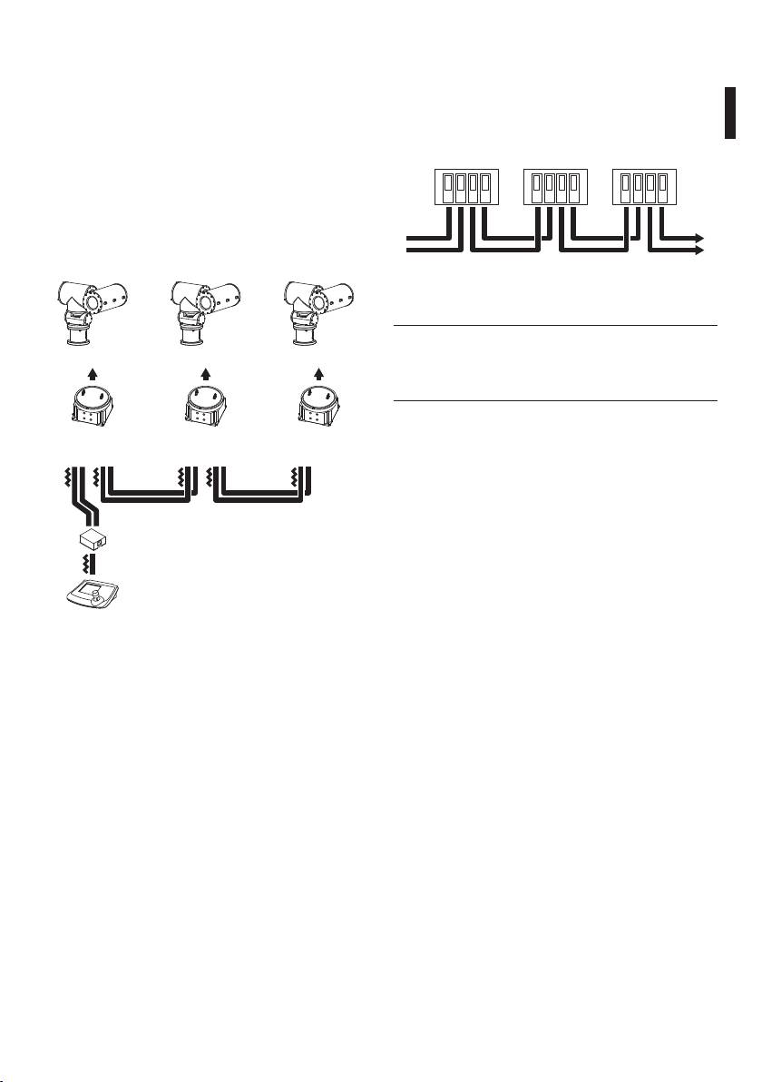
6.2.10 Collegamento di più ricevitori in
I morsetti RX-485A e RX-485B che presentano il carico
inserito, devono essere collegati, rispettivamente, ai
cascata (collegamento punto-punto)
morsetti TX-485A e TX-485B dell’unità precedente,
I ricevitori possono rigenerare internamente il
anch’essi con il carico inserito:
segnale ricevuto e rispedirlo su di una nuova linea
di comunicazione verso il ricevitore successivo.
RS485
RS485
RS485
Ognuno dei tre tratti di linea (L1, L2, L3) è considerato
IT - Italiano - Manuale di istruzioni
indipendente, e collega punto-punto solo due
RX-A
RX-B
TX-A
TX-B
RX-A
RX-B
TX-A
TX-B
RX-A
RX-B
TX-A
TX-B
dispositivi, entrambi con carico inserito, per una
lunghezza massima di 1200m. La distanza tra tastiera
e ricevitore D può quindi raggiungere i 3600m
(1200m tra la tastiera ed il ricevitore B, 1200m tra
il ricevitore B ed il ricevitore C, e altri 1200m tra il
ricevitore C ed il ricevitore D, per un totale di 3600m).
Dal ricevitore
Al ricevitore
precedente
successivo
Fig. 10
Nel caso del collegamento in questione
j
(punto-punto) il malfunzionamento di uno
EXPT
EXPT EXPT
dei ricevitori comporta l’interruzione dei
dispositivi in cascata.
C DB
6.2.11 Più ricevitori per linea,
EXDTRX3
EXDTRX3
EXDTRX3
collegamento con doppino twistato
EXDTRX324
EXDTRX324
EXDTRX324
(collegamento multipunto)
Tutti i ricevitori collegati ad una stessa linea devono
L1
usare il medesimo protocollo di comunicazione
L2
L3
RS485.
A
Per ciascuna delle linee valgono le seguenti
considerazioni:
• Solo una delle tastiere (quella posta ad un capo
della linea) presenta il carico inserito;
DCT
• Solo uno dei ricevitori (posto all’altro capo della
Fig. 09
linea) presenta il carico inserito;
• La lunghezza complessiva della linea non deve
Il collegamento tra la tastiera e il primo ricevitore
superare i 1200m.
deve essere eseguito secondo lo schema indicato in
Fig. 08, pagina 12.
13
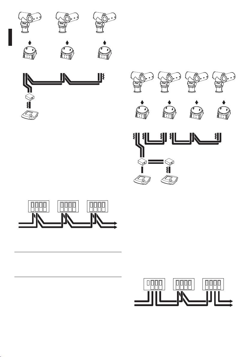
6.2.12 Configurazioni miste (punto-
punto / multipunto)
Risulta essere una combinazione dei due modi
di collegamento precedenti, e a seconda della
EXPT EXPTEXPT
combinazione scelta consente di sfruttare al meglio
i vantaggi dei due tipi di collegamento riducendo
A2 A3A1
in maniera anche significativa la possibilità di
malfunzionamento.
EXDTRX3
EXDTRX3
EXDTRX3
Ecco un esempio di collegamento misto:
EXDTRX324
EXDTRX324
EXDTRX324
A
EXPTEXPT
EXPT EXPT
IT - Italiano - Manuale di istruzioni
R2R1
R3 R4
DCT
EXDTRX3
EXDTRX3
EXDTRX3
EXDTRX3
EXDTRX324
EXDTRX324
EXDTRX324
EXDTRX324
Fig. 11
È stata utilizzata la linea A della tastiera per la
L1
comunicazione verso la telemetria. Gli estremi
L4L3L2
(Tastiera - Ricevitore A3) devono avere la resistenza di
terminazione inserita. I ricevitori A1, A2 non devono
K2
K1
avere la resistenza di terminazione inserita. La
L1
lunghezza massima della linea, da capo a capo (dalla
tastiera al ricevitore A3), è di 1200m.
RS485
RS485
RS485
DCTDCT
RX-A
RX-B
TX-A
TX-B
RX-A
RX-B
TX-A
TX-B
RX-A
RX-B
TX-A
TX-B
Fig. 13
Nell’esempio proposto, un eventuale blocco del
ricevitore R3 (collegato in multipunto sulla linea L3)
non causa il malfunzionamento del ricevitore R4. R3
non è ai capi della linea L3, e quindi non deve essere
terminato.
Dal ricevitore
Al ricevitore
precedente
successivo
Se il ricevitore R2 dovesse bloccarsi, essendo questo
il "generatore" della linea L3, tutti i ricevitori ad
Fig. 12
esso collegati in cascata (R3 ed R4) non riceveranno
comandi.
Nel caso del collegamento in questione
j
(multipunto), il malfunzionamento di
RS485
RS485
RS485
uno dei dispositivi non influenza gli altri
ricevitori.
RX-A
RX-B
TX-A
TX-B
RX-A
RX-B
TX-A
TX-B
RX-A
RX-B
TX-A
TX-B
Dal ricevitore
Al ricevitore
precedente
successivo
Fig. 14
14
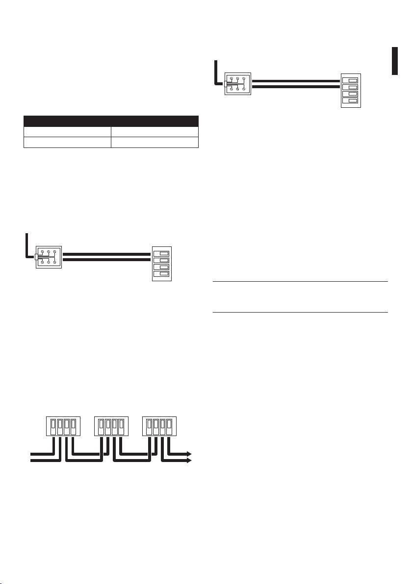
6.2.13 Collegamento con la linea
6.2.14 Collegamento con la linea RS232
Current Loop
Al connettore
Morsetti sul
I diversi dispositivi possono essere collegati
RJ11 della
tastiera
ricevitore
direttamente tramite cavo telefonico fornito dal
fabbricante.
RS232
TX RS232 (Nero)
IT - Italiano - Manuale di istruzioni
Per le normali connessioni sul campo, fare riferimento
RX
GND
ai collegamenti effettuati tramite le scatole di
GND RS232 (Verde)
derivazione RJ, fornite dal fabbricante, secondo le
tabelle di riferimento riportate di seguito:
Fig. 17 Modalità di comunicazione RS232, distanza max 15m.
TASTIERA EXDTRX3, EXDTRX324
TX CL Giallo Morsetto RX CL
6.2.15 Regolazione della tensione di
GND CL Rosso Morsetto AGND
controllo dell’ottica
Tab. 02 Modalità di Comunicazione Current Loop, distanza max
• Collegare il cavo di alimentazione e alimentare
1500m dal ricevitore, jumper JP2 e JP3 in posizione CL.
l’unità (LD1 acceso);
Dal lato ricevitore il collegamento deve essere
• Inserire un carico tra i morsetti FOCUS NEAR e
effettuato ai morsetti RXCL e AGND secondo lo
FOCUS FAR che assorba almeno 10 mA (utilizzare
schema seguente:
una resistenza di valore compreso tra 100 e 1000
ohm);
Al connettore
RJ11 della
Morsetti sul
• Posizionare i puntali del tester sui morsetti FOCUS
tastiera
ricevitore
NEAR e FOCUS FAR;
CURRENT LOOP
• Tenere premuto uno dei due tasti FOCUS sull’unità
TX CL (Giallo)
di comando;
RX
AGND
• Regolare la tensione di controllo dell’ottica agendo
GND CL (Rosso)
TX
AGND
sul trimmer TR1 (default 12Vdc).
Evitare di regolare la tensione a vuoto
Fig. 15
h
(senza inserire il carico) altrimenti la
• Se il ricevitore è collegato in cascata ad un’altra
regolazione risulterà errata.
unità EXDTRX3 / EXDTRX324, la modalità di
ricezione deve essere settata in Current Loop con i
jumper JP2 e JP3 in posizione CL;
• I morsetti RX CL e AGND devono essere collegati,
rispettivamente, ai morsetti TX CL e AGND
dell’unità precedente secondo il seguente schema:
Current
Current
Current
Loop
Loop
Loop
RX
AGND
TX
AGND
RX
AGND
TX
AGND
RX
AGND
TX
AGND
Dal ricevitore
Al ricevitore
precedente
successivo
Fig. 16
15

6.2.16 Collegamento dei cavi del
6.2.18 Test del ricevitore
brandeggio e delle ottiche
Dopo aver connesso i cavi per il brandeggio e
l’ottica, per controllare il corretto funzionamento dei
Prima di effettuare le seguenti operazioni
dispositivi è possibile lanciare una procedura di test
g
assicurarsi che la tensione di controllo del
automatico che rivelerà le funzioni disponibili.
brandeggio e l’impostazione del tipo di
ottiche utilizzati siano corretti.
Il brandeggio, durante il test, si muove
h
automaticamente. Non appoggiarsi ad esso,
• Togliere alimentazione all’unità;
né frapporre ostacoli durante la sua corsa.
• Effettuare i collegamenti con ottica e brandeggio;
Procedere secondo le seguenti indicazioni:
• Dare alimentazione all’unità.
• Accendere il ricevitore;
In caso di ottiche e brandeggi con funzioni
• Identificare il tasto freccia Up (tasto P4) e il tasto di
h
di PRESET (PAN, TILT, ZOOM, FOCUS e IRIS,
reset (tasto P1);
VCC e GND), la lunghezza massima dei
• Tenendo premuto il tasto Up premere il pulsante
cavi di preset non deve superare i 5m di
IT - Italiano - Manuale di istruzioni
di reset;
lunghezza, pena un non preciso ritorno
sulle posizioni memorizzate.
• Rilasciare il tasto di reset (mantenendo il tasto Up
premuto): inizia l’autotest;
6.2.17 Settaggio del ricevitore per le
• Dopo l’inizio del test, rilasciare il tasto Up.
funzioni di PRESET
Il ricevitore attiva una funzione alla volta, per circa 3
Il ricevitore presenta le funzioni di preset integrate
secondi:
(relative al brandeggio e alle ottiche).
• Pan: Sinistra-destra (Led P)
È possibile memorizzare fino ad un massimo di
• Tilt: Basso-alto (Led T)
40 posizioni, con protocollo PELCO D e MACRO,
• Zoom: Wide-tele (Led Z)
richiamabili tramite tastiera con le funzioni di Scan e
Patrol.
• Focus: Far-near(Led F)
Il ricevitore è in grado di riconoscere in maniera
• Iris: Close-open (Led I)
automatica mediante un test quali funzioni di preset
Il risultato del test è indicato dai 5 led P, T, Z, F, I
sono presenti e risulta pertanto agevole configurare
(posti nella parte del ricevitore vicina ai tasti freccia,
il dispositivo. Tuttavia è necessario procedere con
Fig. 06, pagina 10) al termine del movimento di
alcune precauzioni:
brandeggio ed ottiche:
• Prima di effettuare il test del ricevitore (che
• Led acceso fisso: La funzione corrispondente
determina quali funzioni di preset sono attive)
(PAN= P, TILT= T, ZOOM= Z, FOCUS= F, IRIS= I)
assicurarsi di aver collegato in maniera corretta i
opera correttamente;
cavi relativi al brandeggio e alle ottiche;
• Led acceso lampeggiante: La funzione
• Per i cavi di preset (PAN, TILT, ZOOM, FOCUS, IRIS,
corrispondente non funziona correttamente
VCC e GND) usare cavi di lunghezza non superiore
oppure non è presente e non può essere utilizzata
a 5m.
per le operazioni di preset/scan/patrol.
Dopo qualche secondo dalla fine del test il
ricevitore si resetta automaticamente e riprende il
funzionamento normale.
Un lampeggiamento di almeno uno
h
dei led alla fine del test (a meno che
la funzione non sia assente) indica un
malfunzionamento al quale si deve porre
rimedio prima della messa in opera del
ricevitore.
16

6.2.19 Uso dei contatti di allarme
6.2.22 Comandi PELCO D riconosciuti
I quattro contatti di allarme presenti nel ricevitore
da ricevitore
EXDTRX3 / EXDTRX324 sono associati alle prime
Oltre ai comandi standard del protocollo PELCO
quattro posizioni di preset; se l’allarme è attivato, il
D relativi alla movimentazione del brandeggio e
brandeggio e l’ottica si portano nella posizione di
al controllo delle ottiche, il ricevitore è in grado di
preset corrispondente; l’ultimo allarme arrivato ha
riconoscere ed eseguire anche i seguenti comandi
IT - Italiano - Manuale di istruzioni
sempre la priorità più alta. È possibile che EXDTRX3
estesi.
/ EXDTRX324 riceva un comando di allarme anche
COMANDO
attraverso le tastiere di comando DCJ, DCT e DCTEL
COMANDO
EXDTRX3 /
NOTE
(che lo ricevono a loro volta dalle matrici SM164B e
PELCO D
EXDTRX324
SM328B); in tal caso brandeggio ed ottica si portano
Set Auxiliary Aux ON Accetta valori
nella posizione di preset n° 1.
compresi tra 1 e 4
Per poter usare i contatti di allarme è necessario
Clear Auxiliary Aux OFF Accetta valori
impostare i dip di SW4 come segue:
compresi tra 1 e 4
• Dip 3 di SW4 in posizione ON: Contatti di allarme
Set Pattern Start Autopan Toggle --
attivati;
Run Pattern Patrol Toggle --
• Dip 3 di SW4 in posizione OFF: Contatti di allarme
Remote Reset Reset del
--
disattivati;
ricevitore
• Dip 4 di SW4 in posizione ON: Contatti
Go To Preset
Scan Accetta valori
normalmente aperti;
“1÷40”
compresi tra 1
e 40
• Dip 4 di SW4 in posizione OFF: Contatti
normalmente chiusi.
Set Preset “1÷40” Posizione di
Accetta valori
Preset
compresi tra 1
6.2.20 Modalità di funzionamento di
e 40
AUX4
Clear Preset
Reset della
Accetta valori
“1÷40”
singola posizione
compresi tra 1
• Dove agire: Dip 5 di SW4
di Preset
e 40
Impostazioni:
Set Preset “41” Inizio
--
• Dip 5 di SW4 in posizione OFF: Funzionamento
dell’acquisizione
dei parametri per
normale;
il Patrol
• Dip 5 di SW4 in posizione ON: AUX4 si attiva in
Set Preset “…” Patrol “Posizione
Accetta valori
caso di allarme e si disattiva al cessare del segnale
Da”
compresi tra 1
di allarme.
e 40
6.2.21 Tasti locali movimento
Set Preset “…” Patrol “Posizione
Accetta valori
A”
compresi tra 1
brandeggio
e 40
Il ricevitore presenta 4 tasti locali (su scheda) per il
Set Preset “…” Patrol “Pausa” Accetta valori
movimento del brandeggio nelle quattro direzioni
compresi tra 1
(Up, Down, Left, Right, Fig. 06, pagina 10). Essi sono
e 99
molto utili in fase di installazione per movimentare
Set Preset “42” Patrol Start --
il brandeggio al fine di controllare la posizione dei
Set Preset “43” Patrol Stop --
finecorsa e/o la corretta installazione del brandeggio.
I tasti freccia hanno priorità assoluta e pertanto
Set Preset “44” Washer-Wiper* --
quando premuti disattivano momentaneamente
Set Preset “55”
Reset di tutte le
I due comandi
l’utilizzo remoto (tramite tastiere) del ricevitore.
posizioni di Preset
vanno dati in
Set Preset “66”
Quando i tasti freccia sono rilasciati la funzionalità del
sequenza
ricevitore ritorna ad essere pienamente ripristinata.
Tab. 03 * Con la seguente temporizzazione: durante il
Il tasto Up in combinazione con il tasto di reset serve
primo secondo viene attivata solo la funzione
ad eseguire l’autotest ("6.2.18 Test del ricevitore",
Washer, nei successivi due secondi vengono attivate
pagina 16).
contemporaneamente le due funzioni Washer e Wiper,
durante l’ultimo ulteriore secondo viene disattivata la
funzione Washer e lasciata attiva solo la funzione Wiper.
17

6.2.22.1 Esempio di programmazione di una
6.2.24 Tabelle di configurazione dei dip
sequenza di Patrol
switch SW6 e SW4
Si desidera definire una sequenza di Patrol che inizi
SW6
dalla posizione di Preset 19, termini nella posizione di
Dip Stato Funzione
Preset 33 e si fermi per un minuto in ogni posizione
1 ON Protocollo PELCO D
raggiunta:
1 OFF Protocolli VIDEOTEC o MACRO
: Abilitazione all’acquisizione dei parametri;
(impostando il dip 8 di SW4)
: Posizione di inizio del Patrol pari a 19;
2, 3, 4 Ininfluente Nessuna
: Posizione finale del Patrol pari a 33;
: Pausa di 60 secondi in ogni posizione
SW4
raggiunta;
Dip Stato Funzione
: Inizio della sequenza;
1, 2 OFF, OFF 9600 baud* (VIDEOTEC e
MACRO), 2400 PELCO D
: Fine della sequenza.
1, 2 ON, OFF 300 baud VIDEOTEC, 38400
IT - Italiano - Manuale di istruzioni
6.2.23 Accensione e spegnimento
baud MACRO, 4800 baud
PELCO D
Prima di fornire alimentazione:
1, 2 OFF, ON 1200 baud (VIDEOTEC e
• Controllare se il materiale fornito corrisponde
MACRO), 9600 baud PELCO D
alle specifiche richieste, esaminando le etichette
1, 2 ON, ON 19200 baud (VIDEOTEC,
di marcatura ("4.2 Marcatura del prodotto",
MACRO e PELCO D)
pagina 7);
3 OFF Allarmi non usati*
• Controllare che i fusibili di protezione del ricevitore
3 ON Allarmi usati
EXDTRX3 / EXDTRX324 siano integri;
4 OFF Allarmi N.C.*
• Controllare che il ricevitore e gli altri componenti
dell’impianto siano chiusi e sia quindi impossibile il
4 ON Allarmi N.O.
contatto diretto con parti in tensione;
5 OFF -
• Accertarsi che tutte le parti siano fissate in maniera
5 ON Allarmi su Aux4
solida ed affidabile;
• I cavi di alimentazione non devono essere
6 OFF -
d’intralcio alle normali operazioni del tecnico
6 ON Aux3 e Aux4 a rilascio
installatore ed al movimento del brandeggio;
7 OFF -
• Controllare che le fonti di alimentazione ed i cavi
di collegamento eventualmente utilizzati siano in
8 ON** Protocollo VIDEOTEC
standard****
grado di sopportare il consumo del sistema.
8 OFF*** Protocollo MACRO**** (DCIR,
DCJ, DCT e DCTEL)
Tab. 04 * Impostazioni di default.
** Valido con tastiere DCIR, DCJ, DCT e DCTEL con
protocollo VIDEOTEC standard.
*** Valido con tastiere DCIR, DCJ, DCT e DCTEL con
protocollo MACRO.
**** Selezionabile solo se il dip 1 di SW6 è in posizione
OFF.
18
