Videotec MAXIMUS MPXT: инструкция
Раздел: Видеотехника
Тип:
Инструкция к Videotec MAXIMUS MPXT
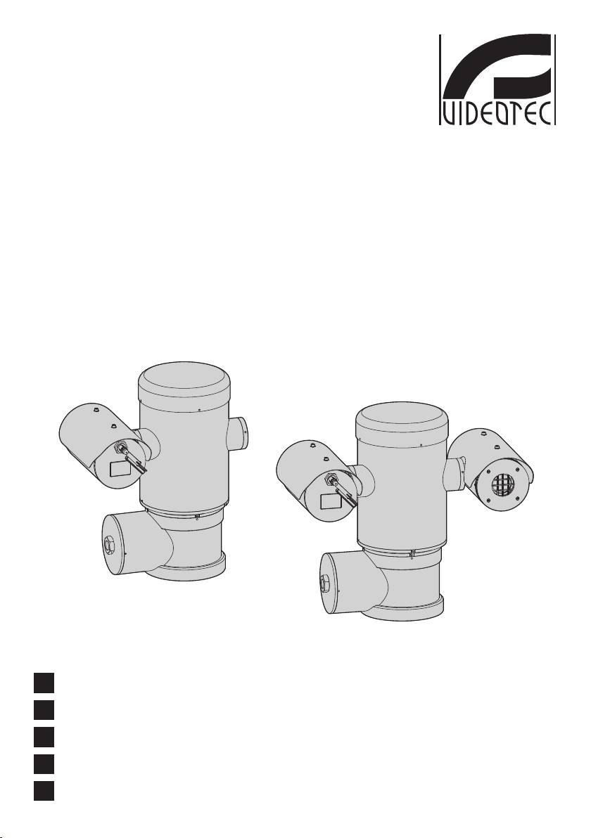
MAXIMUS MPX -
MAXIMUS MPXT
Explosion proof stainless steel PTZ positioning system
EN
English - Instructions manual
IT
Italiano - Manuale di istruzioni
FR
Français - Manuel d’instructions
DE
Deutsch - Bedienungslanleitung
RU
-
ENGLISHITALIANOFRANÇAISDEUTSCH

MAXIMUS MPX -
MAXIMUS MPXT
Explosion proof stainless steel PTZ positioning system
EN
English - Instructions manual
ENGLISH


Contents
ENGLISH
Instructions manual - English - EN
1 About this manual ......................................................................................................... 7
1.1 Typographical conventions .................................................................................................................................. 7
2 Notes on copyright and information on trademarks .................................................. 7
3 Safety rules..................................................................................................................... 7
4 Identication .................................................................................................................. 9
4.1 Product description and type designation..................................................................................................... 9
4.1.1 Version with thermal imaging camera ........................................................................................................................... 10
4.2 Product markings ..................................................................................................................................................10
5 Preparing the product for use .................................................................................... 11
5.1 Safety precautions before use ...........................................................................................................................11
5.2 Unpacking and contents .....................................................................................................................................12
5.2.1 Unpacking ................................................................................................................................................................................ 12
5.2.2 Contents .................................................................................................................................................................................... 12
5.3 Safely disposing of packaging material .........................................................................................................12
5.4 Preparatory work before installation .............................................................................................................. 13
5.4.1 Fixing to parapet or ceiling mount .................................................................................................................................13
5.4.2 Fixing with bracket ................................................................................................................................................................14
5.4.3 Fixing the unit to the pole mount adapter or corner mount adapter ................................................................ 14
5.4.3.1 Fixing with pole mount ............................................................................................................................................................................14
5.4.3.2 Fixing with corner adapter ......................................................................................................................................................................15
5.4.4 Fixing the sunshield .............................................................................................................................................................. 15
6 Assembling and installing .......................................................................................... 16
6.1 Installation ................................................................................................................................................................16
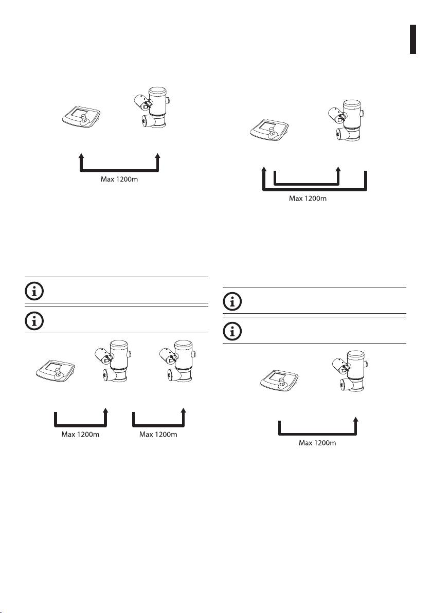
6.1.1 Range of use ............................................................................................................................................................................ 16
6.1.2 Methods of installation........................................................................................................................................................16
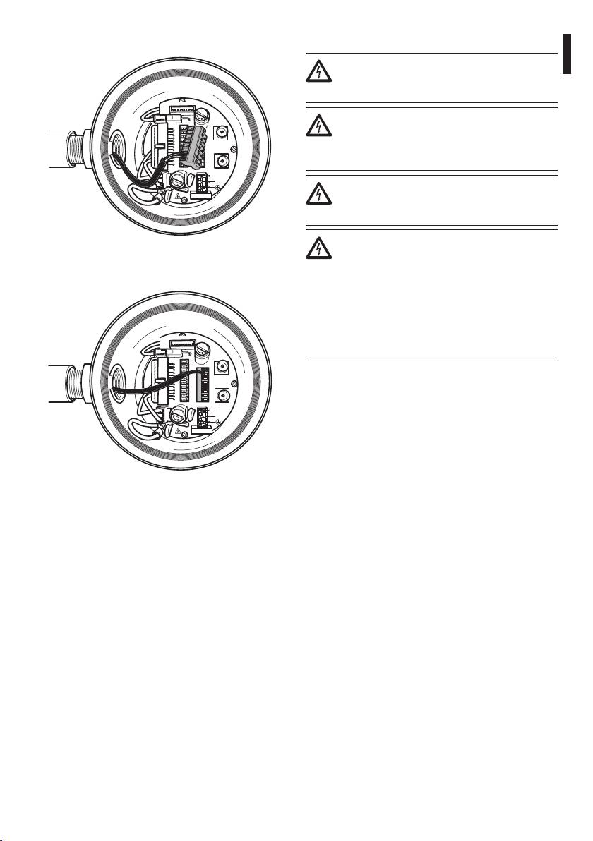
6.1.3 Connecting the cables to the base .................................................................................................................................17
6.1.4 Cable entry ...............................................................................................................................................................................18
6.1.5 Connection of the power supply .....................................................................................................................................19
6.1.6 Connections of one or more video cables ....................................................................................................................21
6.1.7 Connections of one or more optical ber .....................................................................................................................21
6.1.8 Connection of the ethernet cable ...................................................................................................................................22
6.1.9 Telemetry line connections ................................................................................................................................................23
6.1.10 Alarm and relay connections ..........................................................................................................................................24
6.1.10.1 Connecting an alarm with clean contact (dry contact) .............................................................................................................. 24
6.1.10.2 Relay connection ...................................................................................................................................................................................... 24
6.1.11 Unit address, communication protocol and baud rate setting ..........................................................................25
6.1.12 Conguration of the dip-switches ................................................................................................................................25
6.1.13 Setting the conguration check mode .......................................................................................................................25
6.1.14 Setting the baud rate ......................................................................................................................................................... 26
6.1.15 Serial communication lines .............................................................................................................................................26
6.1.15.1 Two-way RS485 TX/RX line ....................................................................................................................................................................27
6.1.15.2 Line RS485-1 reception, line RS485-2 repetition...........................................................................................................................27
6.1.15.3 Two-way RS422 line ................................................................................................................................................................................. 27
6.1.15.4 One-way RS485 line .................................................................................................................................................................................27
3

6.1.16 Serial line terminations and connections ...................................................................................................................28
6.1.17 Setting the protocol ...........................................................................................................................................................28
6.1.18 Setting the address.............................................................................................................................................................28
6.1.19 Earth wiring connection ................................................................................................................................................... 29
6.1.20 Junction box closing .......................................................................................................................................................... 29
7 Instructions for safe operation ...................................................................................30
7.1 Safe operation ......................................................................................................................................................... 30
7.1.1 Commissioning ......................................................................................................................................................................30
7.1.2 Safety rules ...............................................................................................................................................................................31
7.1.3 Explosion prevention rules ................................................................................................................................................31
8 Switching on ................................................................................................................31
EN - English - Instructions manual
8.1 Before powering the device in an explosive atmosphere.......................................................................31
9 Conguration ...............................................................................................................32
9.1 On Screen Menu (OSM) .......................................................................................................................................32
9.1.1 How to use the joystick .......................................................................................................................................................32
9.2 How to move around the menus .....................................................................................................................32
9.3 How to change the settings ...............................................................................................................................33
9.4 How to change the numeric elds ..................................................................................................................33
9.5 How to change text...............................................................................................................................................34
9.6 Conguring the system .......................................................................................................................................35
9.6.1 Main menu ............................................................................................................................................................................... 35
9.6.2 Language .................................................................................................................................................................................. 35
9.6.3 Camera menu ..........................................................................................................................................................................35
9.6.3.1 Zone Titling Menu ......................................................................................................................................................................................36
9.6.3.2 Zone Titling Menu (Edit Zone) ...............................................................................................................................................................36
9.6.3.3 Masking Menu .............................................................................................................................................................................................37
9.6.3.4 Masking Menu (Edit Masks) ....................................................................................................................................................................38
9.6.3.5 How to create a new mask ......................................................................................................................................................................38
9.6.3.6 How to modify a mask ..............................................................................................................................................................................39
9.6.3.7 Advanced Setting Menu...........................................................................................................................................................................40
9.6.3.8 Advanced Setting Menu (Zoom) ........................................................................................................................................................... 40
9.6.3.9 Advanced Setting Menu (Focus) ...........................................................................................................................................................41
9.6.3.10 Advanced Setting Menu (Exposure) .................................................................................................................................................. 41
9.6.3.11 Advanced Setting Menu (Infrared) ....................................................................................................................................................42
9.6.3.12 Advanced Setting Menu (White Balance)........................................................................................................................................43
9.6.3.13 Advanced Setting Menu (Other) .........................................................................................................................................................44
9.6.4 Movement Menu ...................................................................................................................................................................44
9.6.4.1 Manual Control Menu ...............................................................................................................................................................................45
9.6.4.2 Manual Control Menu (Limits) ...............................................................................................................................................................45
9.6.4.3 Preset Menu .................................................................................................................................................................................................. 45
9.6.4.4 Preset Menu (Edit Preset) ......................................................................................................................................................................... 46
9.6.4.5 Preset Menu (Preset Utilities)..................................................................................................................................................................46
9.6.4.6 Patrol Menu ...................................................................................................................................................................................................47
9.6.4.7 Autopan Menu ............................................................................................................................................................................................. 47
9.6.4.8 Motion Recall Menu ................................................................................................................................................................................... 47
9.6.4.9 Advanced Menu ..........................................................................................................................................................................................48
9.6.5 Display Menu ..........................................................................................................................................................................48
9.6.6 Options Menu .........................................................................................................................................................................49
9.6.6.1 Alarms Menu ................................................................................................................................................................................................49
9.6.7 Washer Menu ..........................................................................................................................................................................50
4

9.6.8 Default Menu ..........................................................................................................................................................................50
9.6.9 Info Menu .................................................................................................................................................................................50
9.6.10 Thermal Camera Menu ...................................................................................................................................................... 51
Instructions manual - English - EN
9.6.10.1 Flat Field Correction Menu ....................................................................................................................................................................52
9.6.10.2 Flat Field Correction Menu (Gain Switch Values) ..........................................................................................................................53
9.6.10.3 Video Setup Menu ....................................................................................................................................................................................53
9.6.10.4 Gain Control Menu...................................................................................................................................................................................54
9.6.10.5 ROI Setup Menu ........................................................................................................................................................................................ 55
9.6.10.6 Thermal Analysis Menu ..........................................................................................................................................................................55
9.6.10.7 Thermal Analysis Menu (Spot Meter) ................................................................................................................................................55
9.6.10.8 Thermal Analysis Menu (Isotherm) ....................................................................................................................................................56
9.6.10.9 Status Menu ...............................................................................................................................................................................................56
9.7 IP Board Conguration ........................................................................................................................................57
9.7.1 Minimum system requirements .......................................................................................................................................57
9.7.2 Conguration procedure ....................................................................................................................................................57
9.7.2.1 WAN setting ..................................................................................................................................................................................................58
9.7.3 Installing the NVR software ................................................................................................................................................60
9.7.3.1 Controlling PTZ movements ................................................................................................................................................................... 62
9.7.3.2 Preset and load positions .........................................................................................................................................................................63
10 Instructions for safe operation .................................................................................64
10.1 Visualizing the state of the pan & tilt ............................................................................................................64
10.2 Saving the current position (Preset) ............................................................................................................. 65
10.2.1 Quick save .............................................................................................................................................................................. 65
10.2.2 Saving from the Menu ....................................................................................................................................................... 65
10.3 Recalling a position (Scan) ............................................................................................................................... 65
10.4 Enabling Patrol function ................................................................................................................................... 65
10.5 Enabling Autopan Function ............................................................................................................................65
10.6 Recalling a pattern (Tour) .................................................................................................................................65
10.7 Recalling the Home position ...........................................................................................................................66
10.8 Enabling the Wiper (Wiper) .............................................................................................................................66
10.9 Enabling the Washer (Washer) .......................................................................................................................66
10.10 Reboot the device ............................................................................................................................................66
10.11 Manual correction of a preset focusing .................................................................................................... 67
11 Maintaining and cleaning ......................................................................................... 69
11.1 System conguration and statistics display ..............................................................................................69
11.2 Maintenance and cleaning by users .............................................................................................................69
11.2.1 Routine (to be carried out regularly) ............................................................................................................................69
11.2.1.1 Cleaning the glass .................................................................................................................................................................................... 69
11.2.1.2 Cleaning the germanium window ..................................................................................................................................................... 69
11.2.1.3 Cleaning the device ................................................................................................................................................................................. 69
11.2.1.4 Inspecting the cables ..............................................................................................................................................................................69
11.2.2 Extraordinary (to be done only under particular circumstances)......................................................................70
12 Disposal of waste materials ......................................................................................70
13 Troubleshooting ........................................................................................................ 71
14 Technical data ............................................................................................................ 73
14.1 MPX ..........................................................................................................................................................................73
14.1.1 General ....................................................................................................................................................................................73
14.1.2 Mechanical ............................................................................................................................................................................73
5

14.1.3 Electrical/Video ....................................................................................................................................................................73
14.2 Communications .................................................................................................................................................74
14.2.4 Protocols .................................................................................................................................................................................74
14.2.5 Environment .........................................................................................................................................................................74
14.2.6 Certications ......................................................................................................................................................................... 74
14.2.7 Brackets and adapters .......................................................................................................................................................74
14.2.8 Accessories ............................................................................................................................................................................74
14.2.9 Package ...................................................................................................................................................................................74
14.3 MPXT ........................................................................................................................................................................ 75
14.3.1 General ....................................................................................................................................................................................75
14.3.2 Mechanical ............................................................................................................................................................................75
14.3.3 Electrical/Video ....................................................................................................................................................................75
EN - English - Instructions manual
14.4 Communications .................................................................................................................................................76
14.4.4 Protocols .................................................................................................................................................................................76
14.4.5 Environment .........................................................................................................................................................................76
14.4.6 Certications ......................................................................................................................................................................... 76
14.4.7 Brackets and adapters .......................................................................................................................................................76
14.4.8 Accessories ............................................................................................................................................................................76
14.4.9 Package ...................................................................................................................................................................................76
14.5 Electrical rating ....................................................................................................................................................77
14.6 Cable glands ..........................................................................................................................................................77
14.7 Camera ....................................................................................................................................................................78
15 Technical drawings .................................................................................................... 83
A Appendix - Marking codes .......................................................................................... 85
A.1 ATEX Marking ..........................................................................................................................................................85
A.2 IECEx Mark ...............................................................................................................................................................86
A.3 Gas group classication ......................................................................................................................................87
B Appendix - Flamepath ................................................................................................. 88
6
1 About this manual
3 Safety rules
Before installing and using this unit, please read this
The manufacturer declines all responsibility
Instructions manual - English - EN
manual carefully. Be sure to keep it handy for later
for any damage caused by an improper use
reference.
of the appliances mentioned in this manual.
Furthermore, the manufacturer reserves
1.1 Typographical conventions
the right to modify its contents without any
prior notice. The documentation contained
DANGER!
in this manual has been collected with great
Explosion hazard.
care, the manufacturer, however, cannot
Read carefully to avoid danger of explosion.
take any liability for its use. The same thing
can be said for any person or company
DANGER!
involved in the creation and production of
High level hazard.
this manual.
Risk of electric shock. Disconnect the
power supply before proceeding with any
This device must be connected to an
operation, unless indicated otherwise.
earth conductor (protective earth). This
connection must be made only throught
WARNING!
the internal connector J1 (6.1.5 Connection
Medium level hazard.
of the power supply, page19). External
This operation is very important for the
equipotential bonding connections
system to function properly. Please read
must also be performed but only for
the procedure described very carefully and
supplementary bonding connection to
carry it out as instructed.
earth, and required by local codes or
authority.
INFO
Description of system specications.
We recommend reading this part carefully
in order to understand the subsequent
stages.
2 Notes on copyright and
information on trademarks
The quoted names of products or companies are
trademarks or registered trademarks.
Fig. 1
External hole for Equipotential bonding
required by authority. Not to be intended as
protective earth connections.
7

• Read these instructions.
• This device is remotely controlled and may change
position at any time. It should be installed so that
• Keep these instructions.
no one can be hit by moving parts. It should be
• Heed all warnings.
installed so that moving parts cannot hit other
• Follow all instructions.
objects and create hazardous situations.
• To reduce the risk of ignition of hazardous
• Make sure that the device is rmly anchored.
atmospheres, disconnect the equipment from the
• A power disconnect device must be included
supply circuit before opening. Keep the product
in the electrical installation, and it must be very
tightly closed when in operation.
quickly recognizable and operated if needed.
• The equipment is certied for use in ambient
• It is only allowed to open the cover of the on-board
temperatures of -40°C to 60°C (-40°F / 140°F).
junction box for cabling of the device. The other
• Installation of this equipment shall be carried out
lids must be open from the manufacturer.
by suitably trained personnel in accordance with
EN - English - Instructions manual
• Do not use power supply cables that seem worn
the applicable code of practice IEC/EN 60079-14.
or old.
• Recapitulation of the certication marking as
• For technical services, consult only and exclusively
detailed on drawing LABEL_DRAWING.
authorized technicians.
• The temperature of the surfaces of the device
• Before proceeding with installation check the
is increased by exposure to direct sunlight. The
supplied material to make sure it corresponds
surface temperature class of the device was
to the order specication by examining the
determined only with ambient air temperature,
identication labels (4.2 Product markings, page
without taking into consideration direct sunlight.
10).
• Choose an installation surface that is strong
enough to sustain the weight of the device, also
bearing in mind particular environmental aspects,
such as exposure to strong winds.
• Since the user is responsible for choosing the
surface to which the unit is to be anchored, we
do not supply the xing devices for attaching the
unit rmly to the particular surface. The installer is
responsible for choosing xing devices suitable for
the specic purpose on hand. Use methods and
materials capable of supporting at least 4 times the
weight of the device.
8
MAXIMUS PTZ oers continuous, high speed
4 Identification
rotation, positioning precision and superior image
quality, utmost sturdiness and simplied system
Instructions manual - English - EN
4.1 Product description and type
conguration.
designation
Speed and precision are the predominant pan-and-
tilt characteristics, reaching 100°/s in continuous
The MAXIMUS series explosion-proof pan-tilt-
horizontal rotation, with vertical range between -90°
zoom (PTZ) camera positioning devices have been
to +90°.
designed to allow movement, on both a horizontal
and a vertical plane of a in-built camera and to
MAXIMUS PTZ manages the preset, auto-pan and
operate in industrial environments in which there
patrol functions with an accuracy 0.02°.
may be an explosive atmosphere due to gas, vapours,
The unit performs a continuous control of its position
mists, or air or powder mixtures.
to verify the correct positioning of the camera at any
MAXIMUS PTZ devices, supplied complete with an in
time. This is a very useful function in case of severe
built camera, are made of AISI 316L electropolished
environmental conditions, such as strong wind and
stainless steel.
heavy vibrations.
This unit basically consists of a base, a main body and
The choice of integrated SONY cameras oer 36x
a housing for the camera.
and 28x zoom lenses, which allow the recording with
exceptional precision of both close-by and far away
Versions with a second housing for thermal cameras
objects, as well dynamic privacy zone masking.
are available.
Besides the OSD (On Screen Display) conguration,
The base has an on-board junction box that allows
the system is equipped with an RS485 interface for
very easy cabling of the system, and it comprises the
complete system control and for the updating in
power supply electronics. There is a hole 3/4” NPT
remote mode of the latest rmware version.
on the base and the connection must to be done in
conformity with IEC/EN60079-14.
The simplied set-up software interface oers typical
preset congurations or the possibility to customize
The main body contains the motors for horizontal
the complete system.
and vertical movements and the CPU and video
boards.
The camera housing contains a day/night module
with its electronics, an heater and a built-in wiper.
The PTZ device has an IP66 protection degree and
its operating temperature is - 40°C to 60°C (-40°F /
140°F).
MAXIMUS PTZ includes integrated high-performance
pan-and-tilt telemetry.
Fig. 2 MPX.
9
4.1.1 Version with thermal imaging
The high sensitivity NEdT 50mK at f/1.0 ensures an
optimal thermal imaging. It supports 2x or 4x digital
camera
zoom.
The device can be provided with a thermal imaging
A choice of lens sizes is oered between 35mm,
camera, which is installed inside a second housing,
25mm and 9mm, depending on the detection
whose window is made mainly of germanium which
distance required.
guarantees the same strength and security properties
as those for standard glass (Fig. 3 MPXT.,
page10).
The thermal camera is an Uncooled Vanadium Oxide
microbolometer (VOx) with spectral band 7.5-13.5
m; it delivers a thermal video of 320x 256 (PAL) and
320x240 (NTSC), with an image frequency of 8.3fps or
25 fps (PAL) and 7.5 or 30fps (NTSC).
EN - English - Instructions manual
Fig. 3 MPXT.
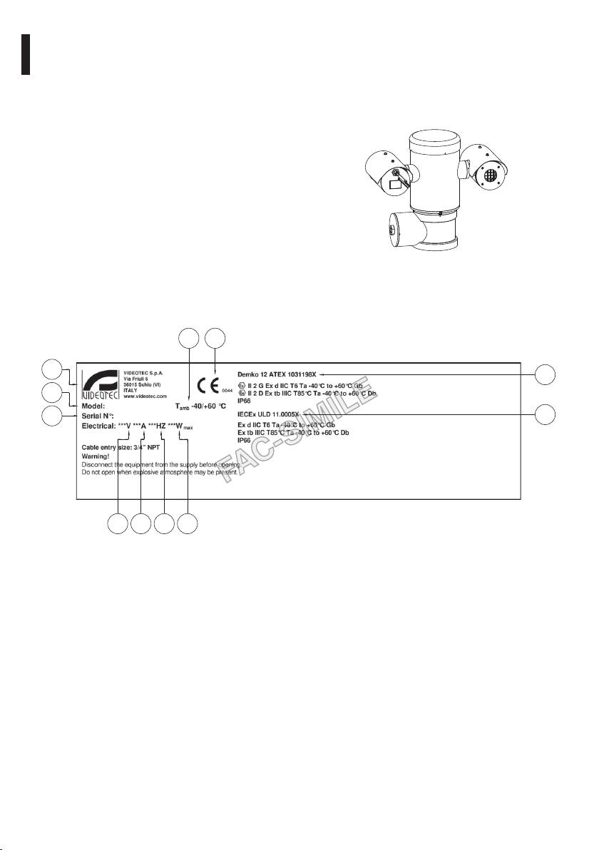
4.2 Product markings
04
01
02
10
03
05
11
06 07 08 09
Fig. 4
1. CE symbol
10. ATEX certication:
2. Manufacturer’s name and address
• ATEX certicate number
3. Model identication code
• Classication for zone type, protection method,
temperature class for which this product may be
4. Ambient temperature of use referring to model
used in compliance with the ATEX directive
identication code
11. IECEx certication:
5. Serial number (the serial number are 12 numeric
characters, the second and the third digits
• IECEx certicate number
dene the last two numbers of the year of
• Classication for zone type, protection method
manufacture)
and temperature class for which this product
6. Power supply voltage (V)
may be used in compliance with the IECEx
standard
7. Absorption current (A)
8. Frequency (Hz)
9. Housing power consumption (W)
10
5 Preparing the product for
The device can only be considered to be
switched o when the power supply has
use
Instructions manual - English - EN
been disconnected and the connection
cables to other devices have been removed.
Any change that is not expressly approved
by the manufacturer will invalidate both
A power disconnect device must be
the guarantee and certication.
included in the electrical installation, and
it must be very quickly recognizable and
Before installation, make sure the power
operated if needed.
supply and protection specications of the
device correspond to those in the original
Before doing any technical work on the
order. Use of unsuitable appliances can
device make sure that the power supply is
cause serious hazards, risking the safety of
disconnected.
personnel and of the installation.
Make connections and tests in the
5.1 Safety precautions before use
laboratory before carrying out installation
on site. Use appropriate tools for the
The electrical installation in which the
purpose.
unit is inserted must be equipped with a
15A maximum bipolar protection circuit
Before proceeding with any operations,
(magnetothermal), that must include a
make sure that the mains voltage is correct.
bipolar automatic-type circuit breaker,
which must also envisage earth fault
For handling there aren’t request of
current protection (magnetothermal +
particular demands to assigned sta,
dierential) with minimum distance of
therefore it is recommended, to carry out
3mm between contacts.
such operation observing the common
rules of accident prevention.
Make sure that all the devices are certied
for the application and for the environment
in which they will be installed.
11

Single Mode/Multi Mode optical ber version:
5.2 Unpacking and contents
• 1 explosion-proof
5.2.1 Unpacking
• 1 sunshield (2 if version with thermal camera)
When the product is delivered, make sure that the
• 1 document Important safety instructions
package is intact and that there are no signs that it
• 3 silicone sheaths
has been dropped or scratched.
• 6 ties
If there are obvious signs of damage, contact the
supplier immediately.
• 2 hexagon socket set screws
Keep the packaging in case you need to send the
• 2 ber optic adapters
product for repairs.
• Instructions manual
5.2.2 Contents
5.3 Safely disposing of packaging
Check the contents to make sure they correspond
EN - English - Instructions manual
material
with the list of materials as below:
Analog version:
The packaging material can all be recycled. The
installer technician will be responsible for separating
• 1 explosion-proof
the material for disposal, and in any case for
• 1 sunshield (2 if version with thermal camera)
compliance with the legislation in force where the
• 1 document Important safety instructions
device is to be used.
• 1 silicone sheath
Bear in mind that if the material has to be returned
• 2 ties
due to a fault, using the original packaging for its
transport is strongly recommended.
• 2 hexagon socket set screws
• Instructions manual
IP version:
• 1 explosion-proof
• 1 sunshield (2 if version with thermal camera)
• 1 document Important safety instructions
• 1 silicone sheath
• 2 ties
• 2 hexagon socket set screws
• 1 CD
• Instructions manual
12
5.4 Preparatory work before
5.4.1 Fixing to parapet or ceiling mount
Attach the adapter (01) to the bottom of the unit
installation
using 4 stainless steel (A4 class 80) socket at head
Instructions manual - English - EN
cap screw M10 x 20mm (02).
Use appropriate tools for the installation.
The particular nature of the site where the
Make sure the thread are free of dirt and debris.
device is to be installed may mean special
Apply a generous amount of thread locking
tools are required for installation.
compound (Loctite 270) into the threaded holes in
the base of the device.
Choose an installation surface that is
Tighten them to 35Nm. The thread compound
strong enough to sustain the weight of
must cure for one hour, allow for this period prior to
the device, also bearing in mind particular
completing the installation.
environmental aspects, such as exposure to
strong winds.
02
It should be installed so that no one can be
01
hit by moving parts. It should be installed
so that moving parts cannot hit other
objects and create hazardous situations.
Make sure that the device is rmly
anchored.
Fig. 5
The device must be installed and
maintained only and exclusively by
Use the external holes in the adapter to x the
qualied technical personnel.
assembled unit to the wall or to the pole. Use screws
that can bear at least 4 times the weight of the unit.
For technical services, consult only and
exclusively authorized technicians.
Ø 200
Since the user is responsible for choosing
the surface to which the unit is to be
anchored, we do not supply the xing
35
devices for attaching the unit rmly to
35
the particular surface. The installer is
responsible for choosing xing devices
35
suitable for the specic purpose on hand. In
35
general use methods and materials capable
of supporting at least four times the weight
Ø 11
of the device.
8
It is possible to install the unit with several brackets.
We strongly recommend using only approved
Ø 238
brackets and accessories during installation.
Fig. 6
13
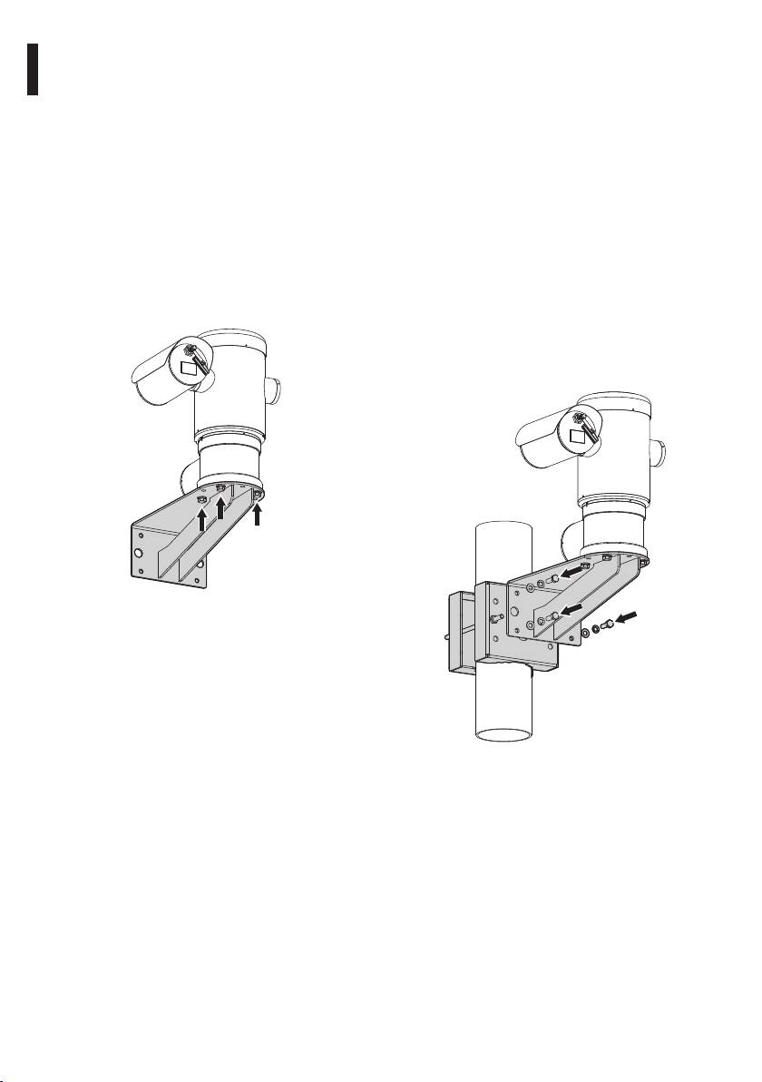
5.4.2 Fixing with bracket
5.4.3 Fixing the unit to the pole mount
The bracket can be xed to the vertical wall. Use
adapter or corner mount adapter
screws and wall xing devices that can bear at least
To install the component on a pole or at a wall corner,
four times the weight of the unit.
rst of all x the pan & tilt unit to the wall bracket (
To x the device to the bracket, use 4 washers, 4
5.4.2 Fixing with bracket, page14).
stainless steel grower washer and 4 hexagon stainless
5.4.3.1 Fixing with pole mount
steel bolts (A4 class 80) M10x20mm.
Fix the wall bracket to the pole mount adapter
Make sure the thread are free of dirt and debris.
using 4 washers, 4 stainless steel grower washer
Apply a generous amount of thread locking
and 4 hexagon stainless steel bolts (A4 class 80)
compound (Loctite 270) into the threaded holes in
M10x30mm.
the base of the device.
Make sure the thread are free of dirt and debris.
Tighten them to 35Nm. The thread compound
Apply a generous amount of thread locking
EN - English - Instructions manual
must cure for one hour, allow for this period prior to
compound (Loctite 270) into the threaded holes in
completing the installation.
the base of the device.
Tighten them to 35Nm. The thread compound
must cure for one hour, allow for this period prior to
completing the installation.
Fig. 7
Fig. 8
14
5.4.3.2 Fixing with corner adapter
5.4.4 Fixing the sunshield
Fix the wall bracket to the corner mount adapter
Before running the wiring, x the sunshield to the
using 4 washers, 4 stainless steel grower washers
camera housing using the screws and washers.
Instructions manual - English - EN
4 hexagon stainless steel bolts (A4 class 80)
Apply a generous amount of thread locking
M10x30mm.
compound (Loctite 270) into the threaded holes in
Make sure the thread are free of dirt and debris.
the base of the device.
Apply a generous amount of thread locking
The thread compound must cure for one hour, allow
compound (Loctite 270) into the threaded holes in
for this period prior to completing the installation.
the base of the device.
Tighten them to 35Nm. The thread compound
must cure for one hour, allow for this period prior to
completing the installation.
Fig. 10
Fig. 9
15
6 Assembling and installing
6.1 Installation
6.1.1 Range of use
Make all installation works and connections
in a non-explosive atmosphere.
The unit is designed for use in a xed location, for
surveillance of areas classied as zone 1-21 and zone
Make sure that all the devices are certied
2-22 potentially explosive atmospheres, using its
for the application and for the environment
embedded cameras.
in which they will be installed.
The installation temperature range is -40°C to 60°C
(-40°F/140°F).
The following procedures should be carried
The device is operative from-40°C to 60°C
out with the power supply disconnected,
(-40°F/140°F).
unless indicated otherwise.
The unit has been built and certied in compliance
EN - English - Instructions manual
The device must be installed only
with directive 94/9/CE ATEX and with the
and exclusively by qualied technical
international standards IECEX, which dene its range
personnel.
of application and minimum safety requirements.
The equipment has not been assessed as a safety
At Start up the system makes some
related device (as referred to by Directive 94/9/EC
automatic calibration movements: do not
Annex II, clause 1.5).
stay in the vicinity of the device when it is
6.1.2 Methods of installation
powered.
The system can be installed only in a standard or
Make sure that the installation complies
inverted position (ceiling mount). When installed
with local regulations and specications.
for inverted operation, the camera orientation and
controller functions are recongured for normal
Videotec strongly recommend to test the device
operation through the system’s software.
conguration and performance in a oce\laboratory
Hardware adjustment is not required for inverted
before putting it in the nal installation site. (6.1.3
operation.
Connecting the cables to the base, page17).
Fig. 11
16
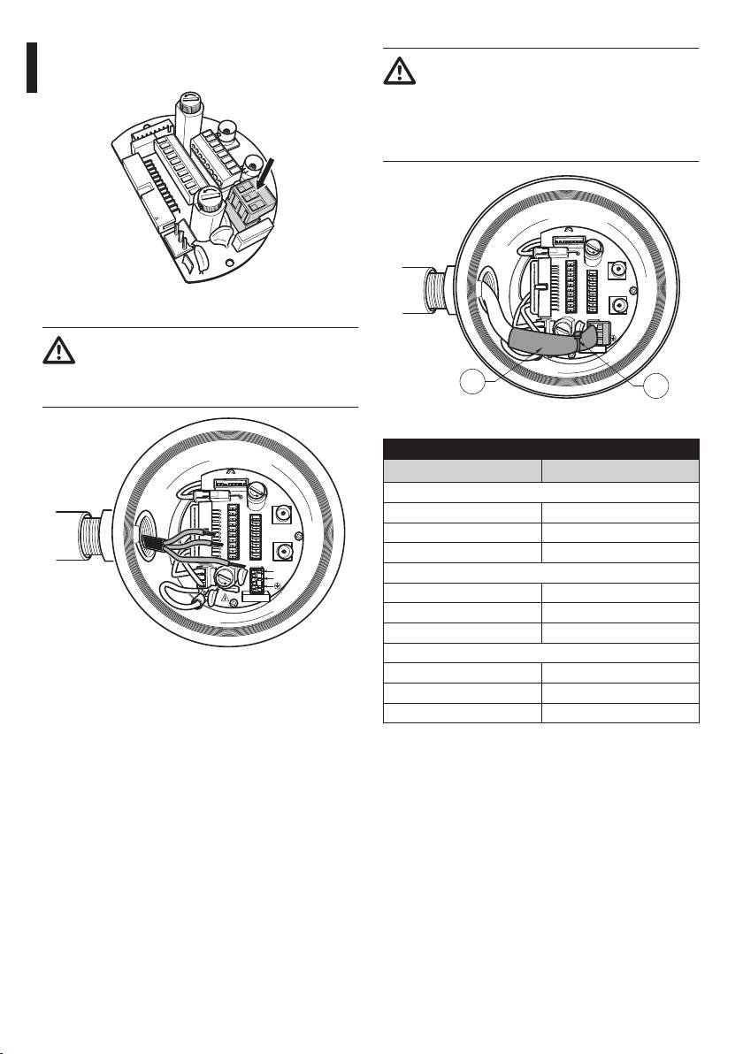
6.1.3 Connecting the cables to the base
It is only allowed to open the cover of the
Before doing any technical work or
on-board junction box for cabling of the
Instructions manual - English - EN
maintenance on the device, make sure
device. The other lids must be open from
that potentially explosive atmosphere is
the manufacturer.
not present. To reduce the risk of ignition
An on-board junction box with 3/4” NPT cable entry is
don’t open the device when a potentially
present on the base of the unit.
explosive atmosphere is present.
A threaded cap gives access to a connection board
The electrical installation in which the
with removable connectors that help the installer to
unit is inserted must be equipped with a
connect the cables.
15A maximum bipolar protection circuit
An hexagon set screw is used to prevent the
(magnetothermal), that must include a
unscrewing of the connection box threaded
bipolar automatic-type circuit breaker,
cap. Remove it before unscrewing the cap.
which must also envisage earth fault
current protection (magnetothermal +
Refer to the following images and information to
dierential) with minimum distance of
connect the wires and cables as required.
3mm between contacts.
To connect the positioning unit remove the hexagon
socket set screw, the plastic cap and the threaded
A power disconnect device must be
cover.
included in the electrical installation, and
The plastic cap thread is available only for shipping
it must be very quickly recognizable and
and cannot be used for operation.
operated if needed.
Before doing any technical work on the
device make sure that the power supply is
disconnected.
The device can only be considered to be
switched o when the power supply has
been disconnected and the connection
cables to other devices have been removed.
Do not use power supply cables that seem
worn or old.
Use adequate cable for higher temperature
Fig. 12
than 80°C. And if installed in an external
ambient below –10°C the cable suitable for
the minimum ambient temperature at point
installation.
17
Inside the junction box you'll nd an address
To make the wirings, unplug the removable
and protocol board and a connectors board with
connector from the connection board, cable all the
removable connectors that make the cabling
conductors on it and then plug the ying connector
procedure easy.
on the board as shown.
Telemetry wiring.
F
U
S
E
J8
J3
FUS2
ADDRESS & PROTOCOL
VIDEO - 1
J2
RL2
J4
F
U
S
E
RL2
J9
J6
RL1
A
RL1
B
J8
J3
FUS2
VIDEO - 1
COM
J2
AL5
A
RS485
RL2
AL4
B
VIDEO - 2
RL2
J9
A
J6
AL3
GND
RL1
W
B
AL2
J7
RL1
AL1
GND
COM
AL5
A
RS485
FUS1
VAR1
AC
IN
J1
AL4
B
VIDEO - 2
L
AL3
GND
F
EN - English - Instructions manual
U
S
E
AL2
W
J7
N
AL1
GND
FUS1
VAR1
AC
IN
J1
VAR2
VAR3
F
U
S
E
L
100nMBW3
N
VAR2
VAR3
100nMBW3
Fig. 13
Fig. 14
6.1.4 Cable entry
Take the J9 removable connector.
Only MPXT series have 2 coax cable video
output.
To prevent the passage of ames or explosions from
the unit to the conduit system or cable gland to the
ADDRESS & PROTOCOL
J4
F
U
S
E
external environment, use connection in conformity
J8
J3
FUS2
J2
VIDEO - 1
RL2
RL2
J9
with IEC/EN60079-14.
J6
RL1
RL1
B
A
COM
AL5
A
RS485
All cable gland devices shall be certied in type of
AL4
B
VIDEO - 2
AL3
GND
AL2
W
J7
AL1
GND
explosion protection “d” and/or "tb", suitable for the
FUS1
VAR1
AC
IN
J1
F
U
S
E
L
conditions of use and correctly installed.
N
VAR2
VAR3
100nMBW3
When conduit is used, a suitable certied stopping
box, in type of explosion protection “d” and/or "tb",
suitable for the conditions of use and correctly
installed. Being tted within 25mm (1in) from the
enclosure wall.
Fig. 15
18
Cable the wires on it.
6.1.5 Connection of the power supply
Always make the electrical connections
Instructions manual - English - EN
with the power supply disconnected and
the circuit-breaker open.
ADDRESS & PROTOCOL
J4
F
U
S
E
When commencing installation make sure
J8
J3
FUS2
VIDEO - 1
J2
RL2
RL2
J9
J6
RL1
A
that the specications for the power supply
RL1
B
COM
AL5
A
RS485
for the installation correspond with those
AL4
B
VIDEO - 2
AL3
GND
AL2
W
J7
required by the device.
AL1
GND
FUS1
VAR1
AC
IN
J1
F
U
S
E
L
N
Make sure that the power source and
VAR2
VAR3
100nMBW3
connecting cables are suitable for the
power consumption of the system.
The building must be equipped with
Fig. 16
a 15A maximum bipolar protection
circuit (magnetothermal), that must
Plug the connector on the board.
include a bipolar automatic-type
circuit breaker, which must also
envisage earth fault current protection
(magnetothermal+dierential) with
ADDRESS & PROTOCOL
minimum distance of 3mm between
J4
F
U
S
E
contacts.
J8
J3
FUS2
VIDEO - 1
J2
RL2
RL2
J9
A
J6
RL1
RL1
B
The device is available in versions for dierent power
COM
AL5
A
RS485
AL4
B
VIDEO - 2
supply voltages: the value for the particular device is
AL3
GND
AL2
W
J7
AL1
GND
shown on its identication label.
FUS1
VAR1
AC
IN
J1
F
U
S
E
L
N
Power cables to be used: AWG16 (1,5mm²).
VAR2
VAR3
100nMBW3
• Earth wire type TEWN with cross section equal or
bigger than line and neutral cable.
• Line and neutral wire type TFFN or MTW
Pass the power cables through the entry device.
Fig. 17
Take from the connectors board the removable male
connector J1. Connect the power wires following
the connector labeling for polarity as shown (Fig. 18,
page20).
19
Protective earth connections, use adequate cable
The power supply cable should also be
sections (up to 2.5mm² or AWG 14)
covered by the silicone sheath (01) supplied
for this purpose, and fastened with the
corresponding tie (02). Furthermore, all
signal cables must be grouped together by
means of a strap (03).
J1
ADDRESS & PROTOCOL
J4
F
U
S
E
J8
J3
FUS2
VIDEO - 1
J2
RL2
RL2
J9
J6
EN - English - Instructions manual
RL1
A
RL1
B
COM
AL5
A
RS485
AL4
B
VIDEO - 2
AL3
GND
AL2
W
J7
AL1
GND
Fig. 18
FUS1
VAR1
AC
IN
J1
F
U
S
L
E
N
Earth cable should be about 10mm longer
VAR2
VAR3
100nMBW3
than the other two, so that it will not be
disconnected accidentally if the cable is
01
02
stretched or pulled.
Fig. 20
POWER SUPPLY CONNECTION
ADDRESS & PROTOCOL
Colour Terminals
J4
F
U
S
E
Power supply 24Vac
J8
J3
FUS2
VIDEO - 1
J2
RL2
RL2
J9
A
J6
Dened by the installer (N) Neutral
RL1
RL1
B
COM
AL5
A
RS485
Dened by the installer (L) Phase
AL4
B
VIDEO - 2
AL3
GND
AL2
W
J7
AL1
GND
Yellow/Green Earth
FUS1
VAR1
AC
IN
J1
F
U
S
L
E
N
Power supply 230Vac
VAR2
VAR3
100nMBW3
Blue (N) Neutral
Brown (L) Phase
Yellow/Green Earth
Power supply 120Vac
Fig. 19
Blue (N) Neutral
Brown (L) Phase
Yellow/Green Earth
Tab. 1
20
6.1.6 Connections of one or more video
6.1.7 Connections of one or more
cables
optical ber
Instructions manual - English - EN
The installation is type CDS (Cable
Use adequate optical ber.
Distribution System), do not connect it to
SELV circuits.
The transmission of video signal or data can be
done by optical ber. In the conguration with
In order to reduce the risk of re, only use
single camera, in the only available optical ber,
cable sizes greater than or equal to 26AWG.
is transmitted the video signal and the telemetry
Suggested coaxial cables are:
control. In the conguration with double camera, the
telemetry control is present only in the optical ber
• RG59
No. 1 (No. 1 on the video, visible camera) whereas in
• RG174A/U UL1354
the optical ber No.2 is transmitted the video signal
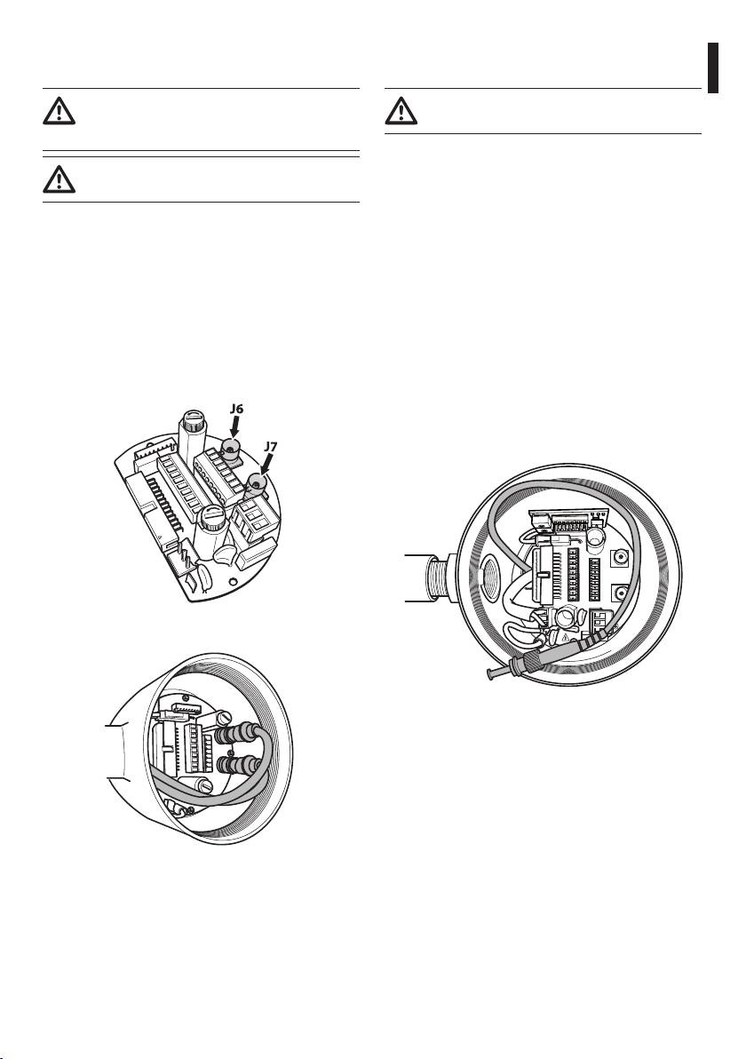
Pass the coaxial cable(s) through the entry device.
of the thermal camera.
Connect the coaxial cable through a 75 Ohm
For Multi Mode ber transmitters, use 62.5/125µm
BNC male connector (not supplied) to video BNC
with a maximum length of 3km. Use a receiver for
connector(s) J6 (and J7).
Multi Mode ber model: FORXMM01
• Connector J6: Main camera output.
For Single Mode ber transmitters, use 9/125µm ber
with a maximum length of 69km. Use a receiver for
• Connector J7: Infrared camera (if present).
Single Mode ber model: FORXSM01
For proper installation:
• Identify the optical ber inside the junction box.
J8
J3
FUS2
VIDEO - 1
J2
RL2
RL2
J9
A
J6
RL1
RL1
B
COM
AL5
A
RS485
AL4
B
VIDEO - 2
AL3
GND
AL2
W
J7
AL1
GND
FUS1
VAR1
AC
IN
J1
L
N
Fig. 21
VAR2
VAR3
100nMBW3
Fig. 23
• Insert the optical ber through the ¾” NPT
threaded entry hole and graft with ST type
connector.
Fig. 22
21
• Insert the silicone sheath supplied for this purpose.
Crimping should be straight-through if passing via
a hub or switch while it should be crossover if you
• Combine the 2 optical bers using ST-ST adapter
are connecting directly to the PC for the necessary
supplied.
checks.
Fig. 24
• Cover the ST-ST adapter with silicone sheath
secure it with a clamp
EN - English - Instructions manual
Fig. 26 Crimped cable.
A
J8
J3
FUS2
VIDEO - 1
J2
RL2
J9
1
2
3
4
5
6
7
8
RL2
RL1
A
J6
RL1
B
COM
AL5
A
RS485
AL4
B
VIDEO - 2
AL3
GND
AL2
W
J7
AL1
GND
FUS1
VAR1
AC
IN
J1
L
N
1
2
3
4
5
6
7
8
VAR2
VAR3
100nMBW3
B
Fig. 27 Straight-through cable.
Fig. 25
A
1
2
3
4
5
6
7
8
• Refer to the manual of the receiver optical ber
for the control of the video and telemetry from
remote.
6.1.8 Connection of the ethernet cable
1
2
3
4
5
6
7
8
B
Operating mode valid only on version with
IP board.
Fig. 28 Crossover cable.
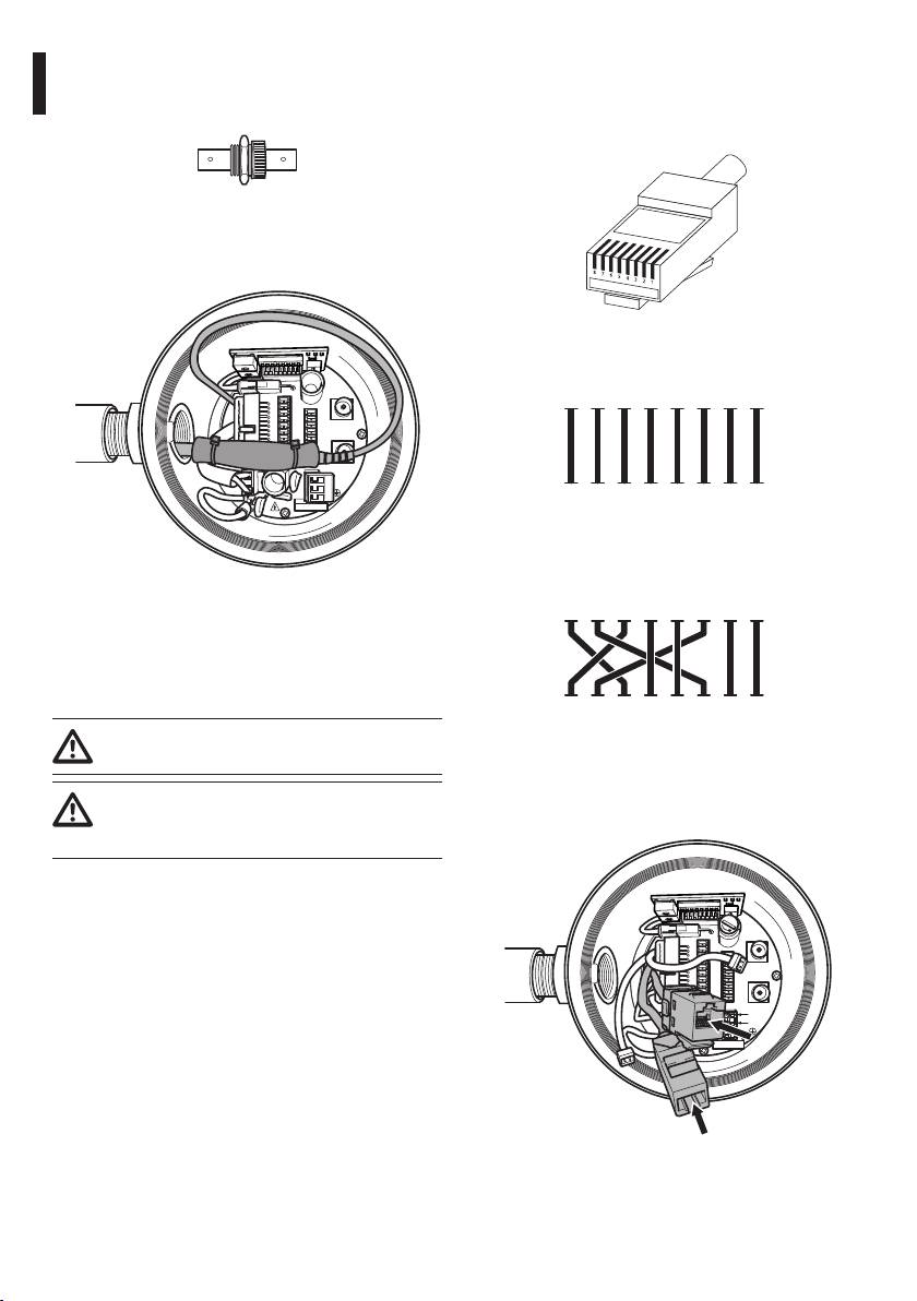
Connect the crimped net cable to connector RJ45
Telemetry transmission and video signal
located on the base of the unit.
pass through the Ethernet cable. Do not
connect cable RS485 and the video cable.
To connect the net cable a UTP, Category 5E or
superior, 4 pair with a maximum length of 100m is
needed.
F
U
S
E
J8
J3
FUS2
VIDEO - 1
J2
Crimp the RJ45 connector on the ethernet cable.
RL2
RL2
J9
J6
RL1
A
RL1
B
COM
AL5
A
RS485
AL4
B
VIDEO - 2
AL3
GND
AL2
W
J7
AL1
GND
FUS1
VAR1
AC
IN
J1
F
U
S
E
L
N
VAR2
VAR3
100nMBW3
Fig. 29
22
The example below shows a typical installation.
• Pass the telemetry cables through the entry device.
• Take the J9 removable female connector from the
connectors board and connect the telemetry wires
Instructions manual - English - EN
to it.
UTP cat 5E
Hub / SwitchPersonal
J9
Computer
UTP cat 5E
F
U
S
E
J8
J3
FUS2
VIDEO - 1
J2
RL2
RL2
J9
J6
RL1
A
RL1
B
COM
AL5
A
RS485
AL4
B
VIDEO - 2
AL3
GND
AL2
W
J7
AL1
GND
FUS1
VAR1
AC
IN
J1
F
U
S
L
E
N
VAR2
VAR3
100nMBW3
Fig. 31
Fig. 30
• Plug the cabled connector to the J9 plug.
6.1.9 Telemetry line connections
TELEMETRY LINES CONNECTION TABLE
The installation is type TNV-1, do not
Serial line Terminal Description
connect it to SELV circuits.
RS485-1 A (+) RS485 line (1)
In order to reduce the risk of re, only use
B (-) RS485 line (1)
cable sizes greater than or equal to 26AWG
SGND RS485-1 line
(0.35mm²)
reference
RS485-2 A (+) RS485 line (2)
The J9 connector supplies 2 RS485 serial
B (-) RS485 line (2)
communication lines (Tab. 2, page23).
SGND RS485-2 line
The lines can be congured in various ways according
reference
to the dip-switch settings of the conguration board
(6.1.11 Unit address, communication protocol and
Tab. 2
baud rate setting, page25).
The last 2 contacts (W and GND) of J9 connector are
Telemetry lines connect the device to control and
referred to the external washer tank level monitoring
programming units (keyboard or PC).
(if present).
23
6.1.10 Alarm and relay connections
6.1.10.1 Connecting an alarm with clean
contact (dry contact)
The alarm contacts are present on J3 connector.
For a clean contact alarm (alarms AL1, AL2, AL3, AL4
and AL5), carry out the following connection:
J3
Clean contact
A1 G
EN - English - Instructions manual
Fig. 32
Fig. 33
The unit is provided with 5 clean contact alarms and
2 output relays with clean contact.
The clean contact alarm can be NO (normally open)
or NC (normally closed).
CONNECTING THE ALARMS AND RELAY
For further details on conguring and using the
Terminal Description
alarms, refer to the related chapter (9.6.6.1 Alarms
RL2 Relay 2 Terminal A
Menu, page49).
RL2 Relay 2 Terminal B
6.1.10.2 Relay connection
RL1 Relay 1 Terminal A
RL1 Relay 1 Terminal B
Relays can be used for low working
voltages only (up to 30Vac or 60Vdc) and
COM A1-A2-A3-A4-A5 alarms
ground
with a maximum current of 1A. Use cables
with a section suitable for the load to be
AL5 Alarm 5 (clean contact)
controlled. Use cables with a minimum
AL4 Alarm 4 (clean contact)
section of 0.25mm² (AWG 30) and maximum
AL3 Alarm 3 (clean contact)
section of 1.5mm² (AWG 16).
AL2 Alarm 2 (clean contact)
Relays do not have polarity and therefore both
AL1 Alarm 1 (clean contact)
terminals of the same relay can be swapped for
Tab. 3
alternating or continuous current voltages.
All alarms have an approximate reach of 200m, which
For further details on conguring and using the
can be obtained using an unshielded cable with a
relays, check the relative chapter (9.6.6.1 Alarms
minimum section of 0.25mm² (AWG 30).
Menu, page49).
• Pass the alarms cables through the entry device.
• Pass the relays cables through the entry device.
• Take the J3 removable female connector from the
• Take the J3 removable female connector from the
connectors board and connect the alarm wires to
connectors board and connect the relays wires to
it.
it.
• Plug the cabled connector to J3 plug.
• Plug the cabled connector to J3 plug.
24
6.1.11 Unit address, communication
6.1.12 Conguration of the dip-switches
protocol and baud rate setting
Operating mode valid only on version with
Instructions manual - English - EN
Before powering the device it must be correctly
IP board.
congured by setting the dip switches on the circuit
The unit can be congured in one way only. Set the
board.
DIP exactly as shown in the table.
Take the conguration board from its J4 connector on
the connector board.
IP BOARD CONFIGURATION
Address 1
Protocol MACRO
J4
Baudrate 38400
Serial line One-way RS485
F
U
S
E
J8
J3
FUS2
VIDEO - 1
Termination of serial line 1 ON
J2
RL2
RL2
J9
RL1
A
J6
RL1
B
Termination of serial line 2 ON
COM
AL5
A
RS485
AL4
B
VIDEO - 2
AL3
GND
AL2
W
J7
Tab. 4
AL1
GND
FUS1
VAR1
AC
IN
J1
F
U
S
L
E
N
Once the dip-switches have been congured, close
VAR2
VAR3
the door and start conguring the IP parameters of
100nMBW3
the pan & tilt.
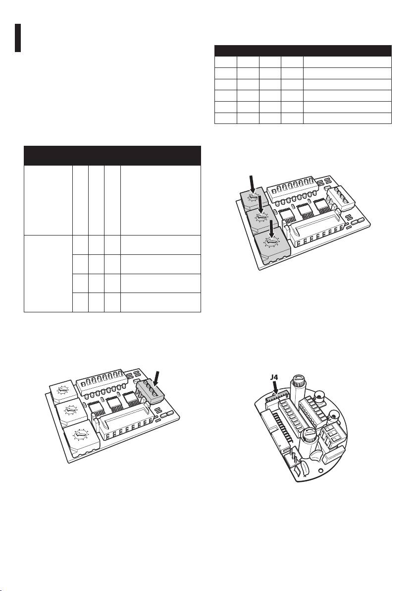
6.1.13 Setting the conguration check
mode
Fig. 34
To set the operating mode operate on DIP 2.
This board is used to set the communication
SW 1=ON: Display Conguration. To be used only
parameters of the serial lines RS485-1 and RS485-
to verify the conguration at the end of the setting.
2: the address of the receiver, the communication
During normal operation make sure the lever is on
protocol and baud rate.
OFF (SW 1=OFF).
O
N
6
7
8
DIP 2
2
3
4
3
4 5
1
1
5
2
2
0
0
A
1
6
3
9
8
7
4
5
I
P
U
3
8
O
N
7
D
1
2
3
4
6
U
2
2
3
4 5
1
5
4
1
5
3
2
0
6
U
1
0
0
A
1
2
9
8
7
3
9
8
7
6
4
4
5
I
P
D
I
P
U
3
2
3
4
D
1
2
3
4
1
U
2
5
5
0
6
U
1
0
9
6
8
7
9
4
8
7
3
I
P
P
I
D
D
1
2
3
4
5
0
6
9
7
3
8
P
I
D
Fig. 35 Address and protocol board.
Fig. 36
25
6.1.14 Setting the baud rate
6.1.15 Serial communication lines
To set the baud rate operate on DIP 2.
To set the serial communication lines operate on
DIP 2.
DIP 2
The product is designed with two RS485 serial
communication lines which can have various settings
7
8
O
N
6
according to the positions of dip-switches 5 and 6 on
2
3
4
3
4 5
1
1
5
A
1
2
2
0
0
3
the DIP selector.
9
8
7
6
4
5
I
P
U
3
D
2
3
4
1
U
2
SERIAL COMMUNICATION LINES DIP 2
5
0
6
U
1
9
8
7
4
I
P
D
2
3
4
1
5
0
6
9
8
7
3
P
I
D
EN - English - Instructions manual
Description
SW 1-2-3-4
SW 5
SW 6
SW 7-8
Conguration (see
related chapters)
Fig. 37
Serial line ON ON Two-way RS485 TX/
Dip-switches 4, 3 and 2 are used to set the
RX line
communication rate of the device according to the
OFF
ON Line RS485-1 reception,
table below.
line RS485-2 repetition
SETTING THE BAUD RATE DIP 2
ON
OFF
Two-way RS422 line
OFF OFF
One-way RS485 line
Tab. 6
Description
SW 1
SW 2
SW 3
SW 4
SW 5-6-7-8
Conguration
Baud rate
ON ON ON 38400 baud
selection
OFF
ON ON 19200 baud
ON
OFF
ON 9600 baud
OFF OFF
ON 4800 baud
ON ON
OFF
2400 baud
OFF
ON
OFF
1200 baud
ON
OFF OFF
600 baud
OFF
OFF
OFF
300 baud
Congurations
ON Display ena-
display
bled
OFF
Display disa-
bled
Tab. 5
26
6.1.15.1 Two-way RS485 TX/RX line
6.1.15.3 Two-way RS422 line
With this type of setting it is possible to obtain a
This setting allows full duplex communication
bi-directional, half/duplex, communication on the
according to the RS422 standard.
Instructions manual - English - EN
RS485-1 line.
Line RS485-1 is always in receiving mode (RS422-RX).
The RS485-2 serial line is not used.
Line RS485-2 is always in transmission mode (RS422-
TX).
Control
RS485-1
keyboard
Control
RS485-1 RS485-2
TX/RX
keyboard
Fig. 38
6.1.15.2 Line RS485-1 reception, line RS485-
Fig. 40
2 repetition
6.1.15.4 One-way RS485 line
With this type of setting it is possible to connect more
The rst line (RS485-1) will operate according to the
than one device in cascade. The signal is repeated
settings in the Address, Baudrate and Protocol dip-
from every unit, making it possible to markedly
switch.
increase total distance.
The RS485-2 serial line is not used.
It only works with mono-directional
protocols.
It only works with mono-directional
protocols.
This conguration does not allow the
remote updating of the rmware.
This conguration does not allow the
remote updating of the rmware.
Control
RS485-1RS485-1 RS485-2
keyboard
Control
RS485-1
keyboard
Fig. 39
Fig. 41
27
6.1.16 Serial line terminations and
Video positioning systems of the P&T can be
controlled by a range of protocols.
connections
SETTING THE PROTOCOL DIP 1
To set the serial line terminations operate on DIP
2.
SW 1 SW 2 SW 3 SW 4 Protocol
The diagram shows two dip-switches that are used to
ON OFF ON OFF PANASONIC
congure termination of the serial line.
OFF OFF ON OFF ERNITEC
Every peripheral that is situated at the end of a line
OFF ON OFF OFF SENSORMATIC
must be terminated using the appropriate dip-switch
ON OFF OFF OFF PELCO D
in order to prevent signal reection and distortion.
OFF OFF OFF OFF MACRO (VIDEOTEC)
Dip-switches 7 and 8 terminate serial lines RS485-1
Tab. 8
and RS485-2 respectively.
6.1.18 Setting the address
EN - English - Instructions manual
SERIAL LINE TERMINATIONS DIP 2 AND
CONNECTIONS
To set the address operate on DIP 3, 4 and 5.
8
O
N
6
7
2
3
4
4 5
1
1
3
2
2
0
6
5
0
A
1
3
9
8
7
4
5
I
P
U
3
D
1
2
3
4
5
U
2
0
6
U
1
9
8
7
4
I
P
Description
SW 1-2-3-4-5-6
SW 7
SW 8
Conguration
D
2
3
4
1
5
Serial line
ON RS485-2 termination
0
6
9
8
7
terminations
enabled
3
P
I
D
OFF
RS485-2 termination
disabled
ON RS485-1 termination
Fig. 43
enabled
Address setting example:
OFF
RS485-1 termination
disabled
Units number 431, dip-switch 3 = 4, dip-switch 4 = 3,
dip-switch 5 = 1.
Tab. 7
Dip 3 set the cent, Dip 4 set the dec, Dip 5 set the
6.1.17 Setting the protocol
unit.
To set the protocol operate on DIP 1.
After you have set your parameters re-connect the
board on the J4 plug of the connection board.
DIP 1
7
8
O
N
6
1
1
2
3
4
2
3
4 5
5
2
0
0
A
1
3
9
8
7
6
4
5
I
P
U
3
D
1
2
3
4
5
U
2
0
6
U
1
9
8
7
4
I
P
D
2
3
4
1
5
0
6
9
8
7
3
P
I
D
Fig. 42
Fig. 44
28
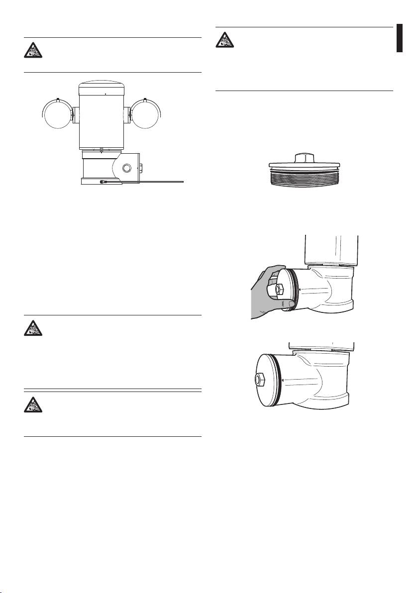
6.1.19 Earth wiring connection
If you suspect that any kind of thread
The positioning unit must be connected to
damaging has occurred, suspend the
Instructions manual - English - EN
an equipotential earth by the threaded M5
installation: the device could be no longer
hole on the base.
safe for the installation on a potentially
explosive atmosphere: in this case contact
Videotec technical support.
Verify that in the cap there isn’t dirt or debris.
Lubricate the threaded part of the lid, of the junction
box and the seal with technical vaseline oil lubricant.
Arrange the cables so that there is no interference
when closing the lid of the junction box.
Fig. 45
Fig. 46
The ring terminal for external bonding connection is
Screw by hand the threaded cap of the junction box
provided by the manufacturer.
till the OR gasket reaches the tube.
The earthing conductor on the external of the unit
must have an actual cross section at least 4mm²
(AWG11).
This is for supplementary bonding connection
required by law. In any case, protective earthing
conductor must be applied to J1 inside connector (
6.1.5 Connection of the power supply, page19).
6.1.20 Junction box closing
If you can’t turn by hand the threaded
Fig. 47
cap before the OR reaches the tube this
means that there are debris\dirt on the
threads or that the cap is misaligned: in
this case there’s a serious danger of threads
damaging; unscrew the cap and check the
alignement and/or clean the threads.
Never force the rotation of threaded cap
before the OR reaches the tube of the
housing, otherwise thread damage could
Fig. 48
occur.
29
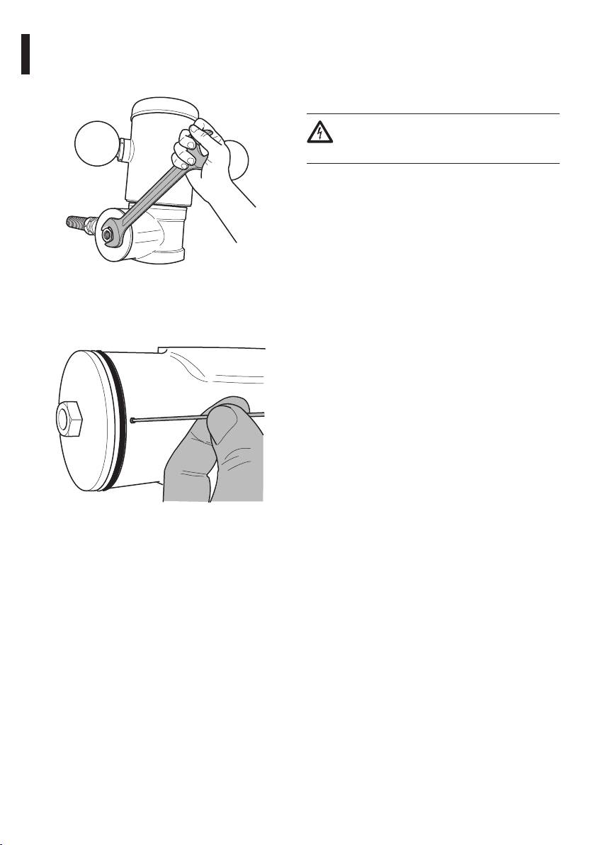
Use a 30mm wrench for tightly closing the threaded
7 Instructions for safe
cap of the junction box. Make sure that there’s no gap
between the threaded cap and the junction box tube
operation
after tightening the cap.
7.1 Safe operation
Before proceeding with the following
operations, make sure that the mains
voltage is correct.
7.1.1 Commissioning
Read the whole of this user’s handbook very carefully
before starting the installation.
EN - English - Instructions manual
Make connections and tests in the laboratory before
carrying out installation on site. Use appropriate tools
for the purpose.
Test system operation for positive results before
Fig. 49
closing the caps and allowing the presence of a
dangerous atmosphere.
Finally tighten the set screw supplied for this purpose
to prevent the unwanted unscrewing of the threaded
Make sure that all the devices are certied for the
cap.
application and for the environment in which they
will be installed.
To reduce the risk of ignition don’t open the device
when a potentially explosive atmosphere is present.
After commissioning the system keep this handbook
in a safe place, available for later consultation.
Fig. 50
30
7.1.2 Safety rules
8 Switching on
Given the considerable weight of the system, use an
appropriate transport and handling system.
The automatic pre-heating (de-ice) process
Instructions manual - English - EN
could be started whenever the device is
Before starting any operation, make sure the power
switched on and the air temperature is
supply is disconnected.
below 0°C. This process is used to ensure
Before powering the system, install an overload
that the device works properly even at
protection device in the electrical equipment for the
low temperatures. The duration ranges
building.
between 60 and 120 minutes, depending
Make sure that all precautions for personal safety
on conditions.
have been taken.
The unit is switched on by simply connecting the
Installation of the electrical equipment must comply
power supply, and switched o by disconnecting the
with the local legislation in force.
power.
The device must be installed only and exclusively by
qualied technical personnel.
8.1 Before powering the device in
7.1.3 Explosion prevention rules
an explosive atmosphere
Use appropriate tools for the area in which you are
Make sure that the unit and other
working.
components of the installation are closed
Always remember that the device must be connected
so that it is impossible to come into contact
to an appropriate earth conductor.
with live parts.
Before doing any technical work or maintenance
on the device, make sure that potentially explosive
Make sure that the junction box cap is
atmosphere is not present.
properly and tightly closed.
Before starting any operation, make sure the power
Make sure (if present) that the sealing of
supply is disconnected.
the seal tting is properly carried out and
Do not open any kind of cap if there is a possibility of
that the sealing compound is completely
your being in a potentially explosive atmosphere.
cured and hardened.
Make all connections, installation and maintenance
work in a non-explosive atmosphere.
Make sure that the device has been
The only cap that the installer have to remove is the
connected to an earth link as described.
junction box cap. Keep any other cap tightly closed.
Make sure that all parts are fastened down
rmly and safely.
31
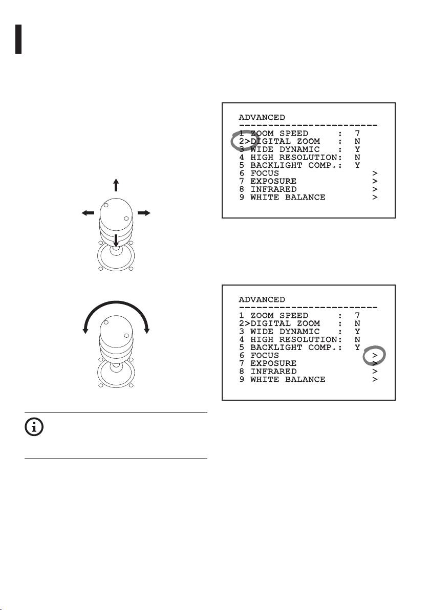
9 Configuration
9.2 How to move around the
menus
9.1 On Screen Menu (OSM)
Each page of the OSM shows a list of parameters or
During the normal operation of the unit it is possible
sub-menus that can be selected by the operator. To
to activate the On Screen Menu in order to set the
scroll through the parameters move the cursor by
advanced functions using the corresponding keys
operating the joystick (up and down).
(for further information, refer to the manual of the
keyboard in use or to Tab. 11, page68).
ADVANCED
Exit the On Screen Menu with Zoom Wide (or Zoom-).
------------------------
1 ZOOM SPEED : 7
9.1.1 How to use the joystick
2>DIGITAL ZOOM : N
All operations in the menus are carried out using the
3 WIDE DYNAMIC : Y
EN - English - Instructions manual
joystick.
4 HIGH RESOLUTION: N
5 BACKLIGHT COMP.: Y
Up
6 FOCUS >
7 EXPOSURE >
8 INFRARED >
9 WHITE BALANCE >
Left Right
Fig. 53
The symbol > at the end of a line indicates the
presence of a specic submenu. To enter the
Down
submenu just conrm the menu item. To exit the
submenu use the Exit function (Zoom Wide).
Fig. 51
ADVANCED
------------------------
1 ZOOM SPEED : 7
2>DIGITAL ZOOM : N
3 WIDE DYNAMIC : Y
Exit Conrm
4 HIGH RESOLUTION: N
5 BACKLIGHT COMP.: Y
6 FOCUS >
7 EXPOSURE >
8 INFRARED >
9 WHITE BALANCE >
Fig. 52
Fig. 54
If using a control keyboard with a dual axis
joystick, use the Zoom Wide and Zoom
Tele keys to carry out the Exit and Conrm
commands.
32
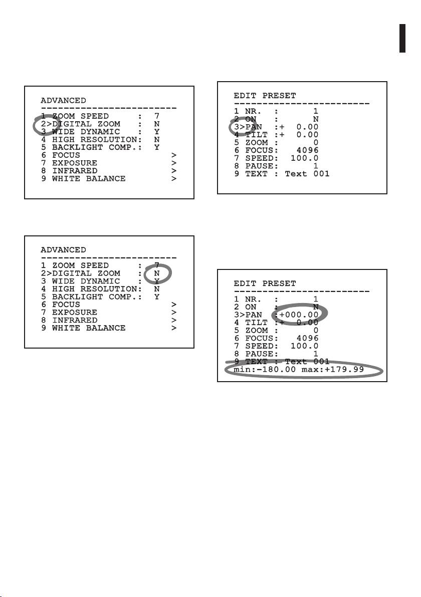
9.3 How to change the settings
9.4 How to change the numeric
Move the cursor to the parameter to be changed and
elds
Instructions manual - English - EN
conrm. The eld will start ashing, indicating that
Move the cursor to the parameter to be changed and
it is in change mode. Operating the joystick (up and
conrm.
down) will show the alternative choices.
EDIT PRESET
ADVANCED
------------------------
------------------------
1 NR. : 1
1 ZOOM SPEED : 7
2 ON : N
2>DIGITAL ZOOM : N
3>PAN :+ 0.00
3 WIDE DYNAMIC : Y
4 TILT :+ 0.00
4 HIGH RESOLUTION: N
5 ZOOM : 0
5 BACKLIGHT COMP.: Y
6 FOCUS: 4096
6 FOCUS >
7 SPEED: 100.0
7 EXPOSURE >
8 PAUSE: 1
8 INFRARED >
9 TEXT : Text 001
9 WHITE BALANCE >
Fig. 57
Fig. 55
The rst digit in the numeric eld to be changed will
After identifying the desired selection, conrm.
ash and the last line of the display will show the
accepted limits for the eld. Move in the eld (left
ADVANCED
and right) and change the sign or the numeric value
------------------------
(up and down).
1 ZOOM SPEED : 7
2>DIGITAL ZOOM : N
3 WIDE DYNAMIC : Y
EDIT PRESET
4 HIGH RESOLUTION: N
------------------------
5 BACKLIGHT COMP.: Y
1 NR. : 1
6 FOCUS >
2 ON : N
7 EXPOSURE >
3>PAN :+000.00
8 INFRARED >
4 TILT :+ 0.00
9 WHITE BALANCE >
5 ZOOM : 0
6 FOCUS: 4096
7 SPEED: 100.0
8 PAUSE: 1
Fig. 56
9 TEXT : Text 001
min:-180.00 max:+179.99
The parameter will stop ashing to conrm the
choice.
Fig. 58
After making the change, conrm. The cursor returns
to the left and the modied gure stops ashing.
The eld will be forced to the minimum or maximum
allowed value if you try to insert a value outside the
limits.
33
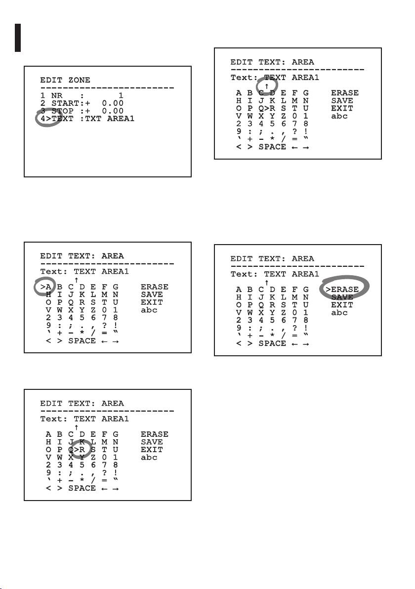
The Conrm command (Zoom Tele) inserts the
9.5 How to change text
desired character.
Move the cursor to the parameter to be changed and
conrm.
EDIT TEXT: AREA
------------------------
Text: TEXT AREA1
EDIT ZONE
↑
------------------------
A B C D E F G ERASE
1 NR : 1
H I J K L M N SAVE
2 START:+ 0.00
O P Q>R S T U EXIT
3 STOP :+ 0.00
V W X Y Z 0 1 abc
4>TEXT :TXT AREA1
2 3 4 5 6 7 8
9 : ; . , ? !
‘ + - * / = “
< > SPACE ← →
EN - English - Instructions manual
Fig. 62
Use:
Fig. 59
• ERASE: To delete the whole text string.
The text editing display will open. The arrow symbol
• SAVE: To store the new text.
will position itself under the character that can be
edited while the cursor > positions itself to the right
• EXIT: To exit the menu.
of the character to be entered.
• abc: To display lower case letters.
EDIT TEXT: AREA
EDIT TEXT: AREA
------------------------
------------------------
Text: TEXT AREA1
Text: TEXT AREA1
↑
↑
>A B C D E F G ERASE
A B C D E F G >ERASE
H I J K L M N SAVE
H I J K L M N SAVE
O P Q R S T U EXIT
O P Q R S T U EXIT
V W X Y Z 0 1 abc
V W X Y Z 0 1 abc
2 3 4 5 6 7 8
2 3 4 5 6 7 8
9 : ; . , ? !
9 : ; . , ? !
‘ + - * / = “
‘ + - * / = “
< > SPACE ← →
< > SPACE ← →
Fig. 60
Fig. 63
You can move inside the menu using the joystick.
To exit the menu you can also use the Zoom Wide
key.
EDIT TEXT: AREA
------------------------
Text: TEXT AREA1
↑
A B C D E F G ERASE
H I J K L M N SAVE
O P Q>R S T U EXIT
V W X Y Z 0 1 abc
2 3 4 5 6 7 8
9 : ; . , ? !
‘ + - * / = “
< > SPACE ← →
Fig. 61
34
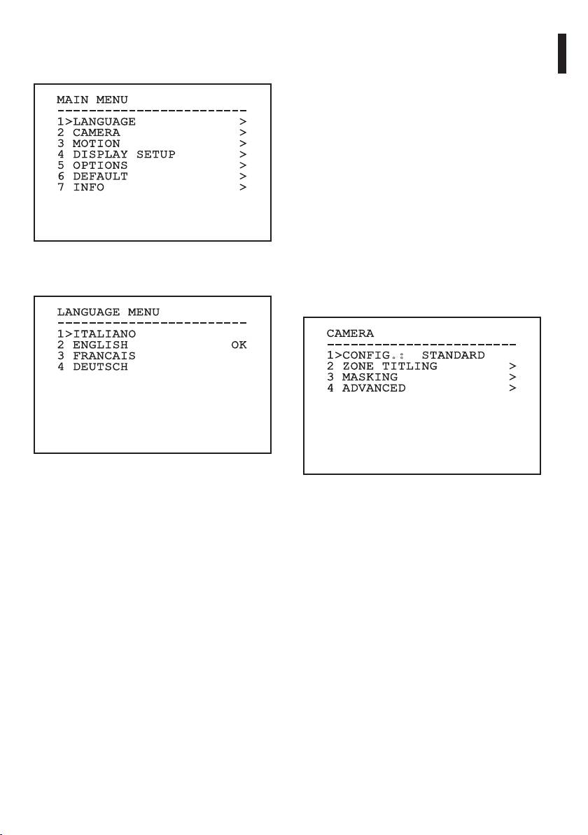
9.6 Conguring the system
9.6.3 Camera menu
1. Conguration: Sets one of the default
9.6.1 Main menu
congurations for the SONY module:
Instructions manual - English - EN
• Standard: Sets the standard operating mode
MAIN MENU
for the camera.
------------------------
1>LANGUAGE >
• Low Light: Sets the operating mode for dimly
2 CAMERA >
lit environments.
3 MOTION >
• Far Mode: Sets the operating mode for large
4 DISPLAY SETUP >
5 OPTIONS >
areas. It enables the proportional zoom and
6 DEFAULT >
the digital zoom.
7 INFO >
• Custom: Signals that the user has manually
selected the parameters of the camera.
2. Area titling: Allows access to the area titling
submenu.
Fig. 64
3. Masking: Allows access to the dynamic masking
submenu.
9.6.2 Language
4. Advanced: Allows access to the advanced
settings submenu of the SONY module.
LANGUAGE MENU
------------------------
1>ITALIANO
CAMERA
2 ENGLISH OK
------------------------
3 FRANCAIS
1>CONFIG.: STANDARD
4 DEUTSCH
2 ZONE TITLING >
3 MASKING >
4 ADVANCED >
Fig. 65
Fig. 66
35
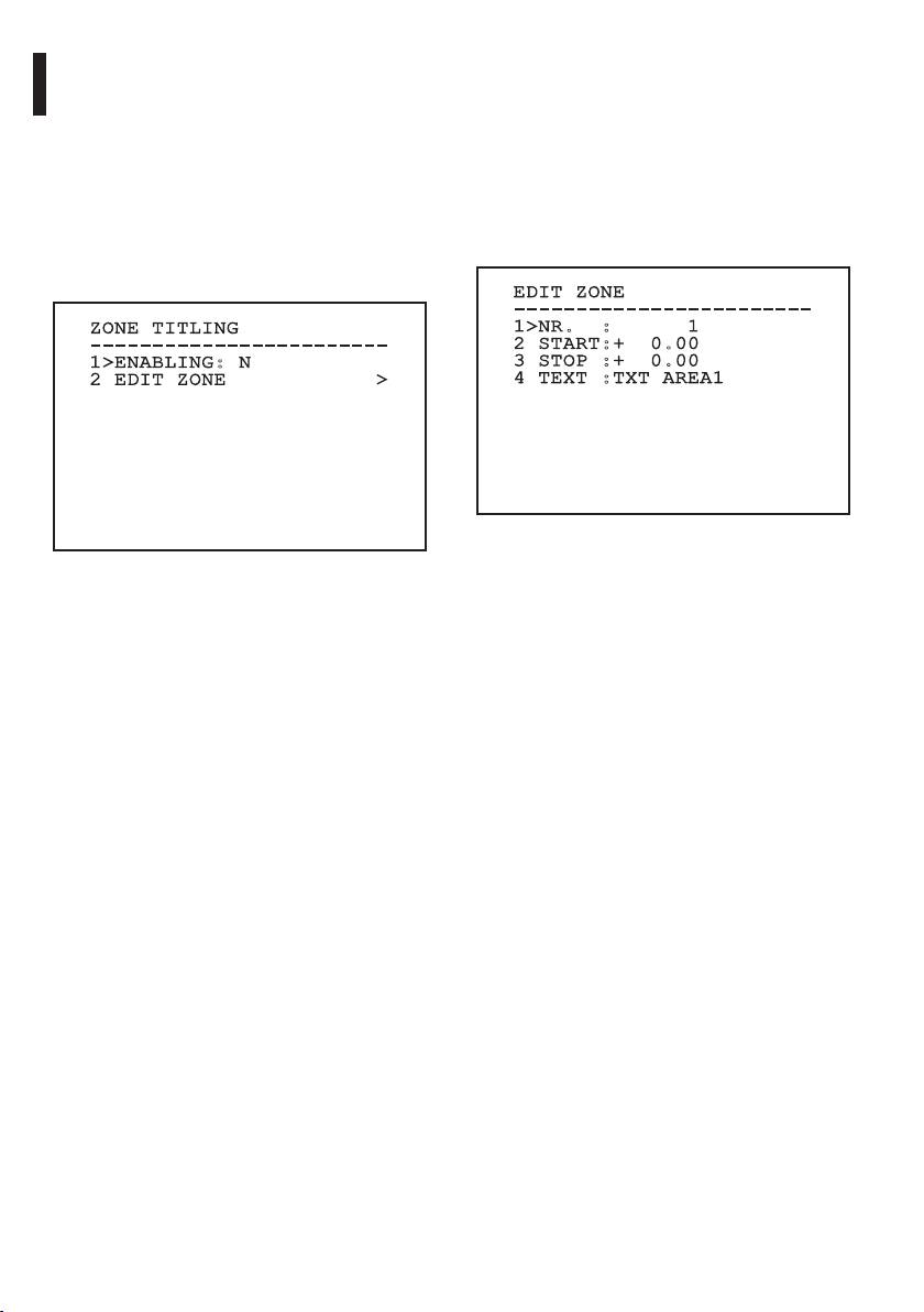
9.6.3.1 Zone Titling Menu
9.6.3.2 Zone Titling Menu (Edit Zone)
This function allows setting up to eight (variable
Once inside the Edit Zone menu it is possible to set
dimension) areas with titling option.
the following parameters.
From the Zone Titling menu it is possible to set the
1. Number: Selects the area to be edited.
following parameters:
2. Start: Sets the initial position of the area.
1. Enabling: To enable onscreen display of the
3. Stop: Sets the nal position of the area.
message associated with the area currently
4. Text: Modies the text which is displayed when
being shown.
moving within the zone.
2. Edit Area: Allows access to the zone parameter
setting submenu .
EDIT ZONE
------------------------
ZONE TITLING
1>NR. : 1
EN - English - Instructions manual
------------------------
2 START:+ 0.00
1>ENABLING: N
3 STOP :+ 0.00
2 EDIT ZONE >
4 TEXT :TXT AREA1
Fig. 68
Example: To enable titling of zone 1 when the device
Fig. 67
is between +15° and +45°, it is necessary to:
• Enable area titling by setting Y as the value of
Enabling under the Area Titling menu.
• Set 1 as the value of parameter Nr under the Edit
Area menu.
• Set +15.00 as the value of parameter Start under
the Edit Zone menu.
• Set +45.00 as the value of parameter Stop under
the Edit Zone menu.
• If necessary, edit the displayed text by selecting
Text under the Edit Zone menu.
36
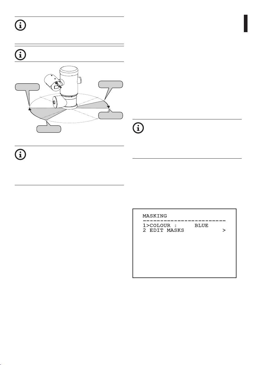
9.6.3.3 Masking Menu
Setting the Start and Stop values of the Edit
Dynamic masking allows the creation of up to a
Zone menu to zero will disable text display.
maximum of 24 masks so as to obtain the masking of
Instructions manual - English - EN
If there are overlapping areas, the area with
certain areas dened by the user.
the highest number will prevail.
Masks are dened in space and take account of the
To dene zones proceed in a clockwise
horizontal, vertical and zoom depth position when
direction, as shown in the gure.
making the settings.
The unit automatically maintains the position and
dimension of the masking, based on the displayed
area.
It is possible to simultaneously display up to 8 masks.
Start1=15°
Stop2=135°
If the device is used at maximum speed, video signal
-90°
0°
updating times become critical and it is necessary to
create masks larger than the object so that it remains
masked for longer during the passage and therefore
cannot be seen.
Stop1=45°
90°-180°
To ensure full functionality, the tilt position
Start2=170°
of the masks must always be between -70
and +70 degrees; in addition , the size of
Fig. 69
the mask must be double the size of the
object to be masked (both height-wise and
The default name and position of the
width-wise).
zones of the pan & tilt refer to the four
cardinal points. The NORTH position can
From the Masking menu it is possible to set the
be modied by means of the Oset Pan
following parameters:
parameter in the movement menu (9.6.4
1. Mask Colour: Allows you to choose the colour
Movement Menu, page44).
of the masks.
2. Edit Masks: Allows access to the Edit Masks
submenu and set the dynamic masking
parameters.
MASKING
------------------------
1>COLOUR : BLUE
2 EDIT MASKS >
Fig. 70
37
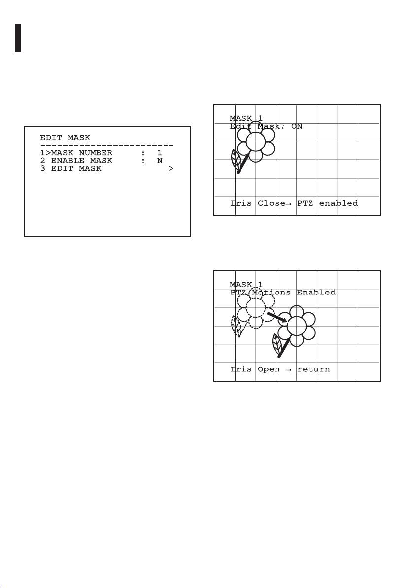
9.6.3.4 Masking Menu (Edit Masks)
9.6.3.5 How to create a new mask
Once inside the Edit Masks menu it is possibile to set
Choose a disabled mask by selecting Mask Number
the following parameters:
from the Edit Masks menu. Select Edit Mask to edit it.
(Fig. 71, page38).
1. Mask Number: Allows you to choose the mask
on which to operate.
In the following example we shall mask a ower.
2. Enable Mask: Enables or disables the selected
• Press the Iris Close button to pass from Masking
mask.
mode to Move Camera mode.
3. Edit Mask: Allows the creation or editing of a
mask.
MASK 1
Edit Mask: ON
EDIT MASK
------------------------
EN - English - Instructions manual
1>MASK NUMBER : 1
2 ENABLE MASK : N
3 EDIT MASK >
Iris Close→ PTZ enabled
Fig. 72
• Operate the joystick on the keyboard to move the
Fig. 71
unit and if necessary operate the zoom to centre
the ower on the screen.
Selecting the option Edit Mask in the menu makes it
possible to set new values for the selected mask.
MASK 1
PTZ Motions Enabled
Iris Open → return
Fig. 73
38
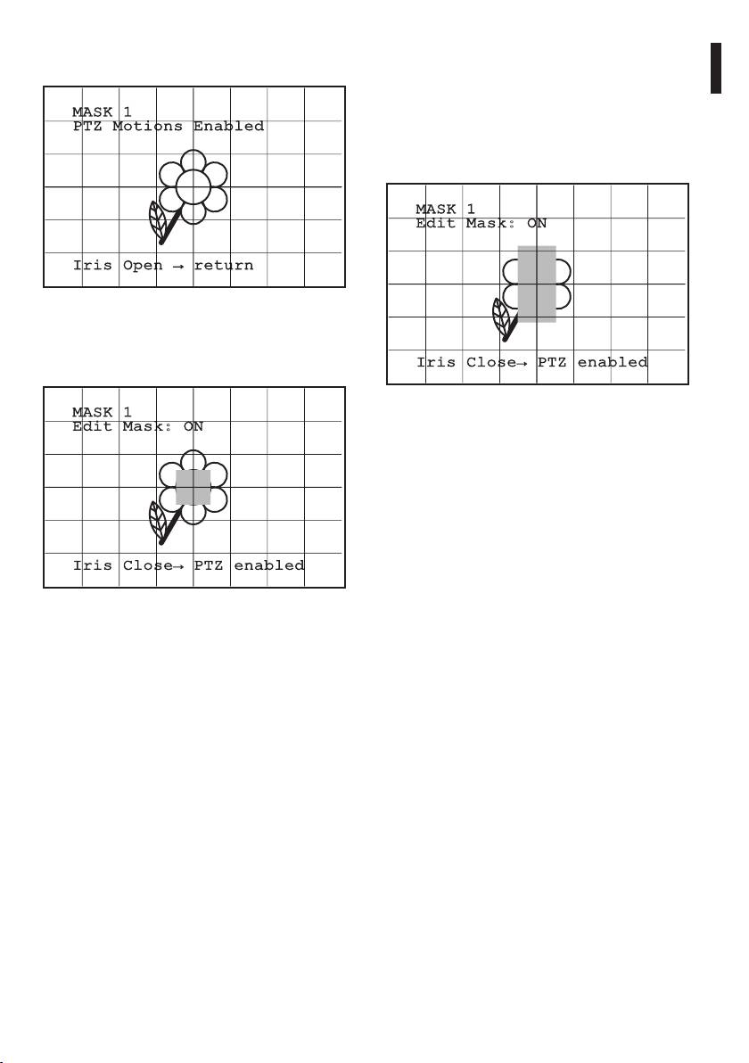
• When the desired result is obtained press the Iris
9.6.3.6 How to modify a mask
Open.
Choose an enabled mask by selecting Mask Number
from the Edit Masks menu (Fig. 71, page38). Select
Instructions manual - English - EN
Edit Mask to edit it.
MASK 1
PTZ Motions Enabled
• Operate the joystick (Pan & Tilt) to enlarge or
reduce the rectangle until the desired eect is
obtained.
MASK 1
Edit Mask: ON
Iris Open → return
Fig. 74
• A small rectangle will appear. Operate the joystick
(Pan & Tilt) to enlarge the rectangle until it covers
Iris Close→ PTZ enabled
the whole ower.
Fig. 76
MASK 1
Edit Mask: ON
• Conrm by turning the zoom to tele.
Iris Close→ PTZ enabled
Fig. 75
• When the desired result is obtained conrm by
turning the zoom to tele.
39
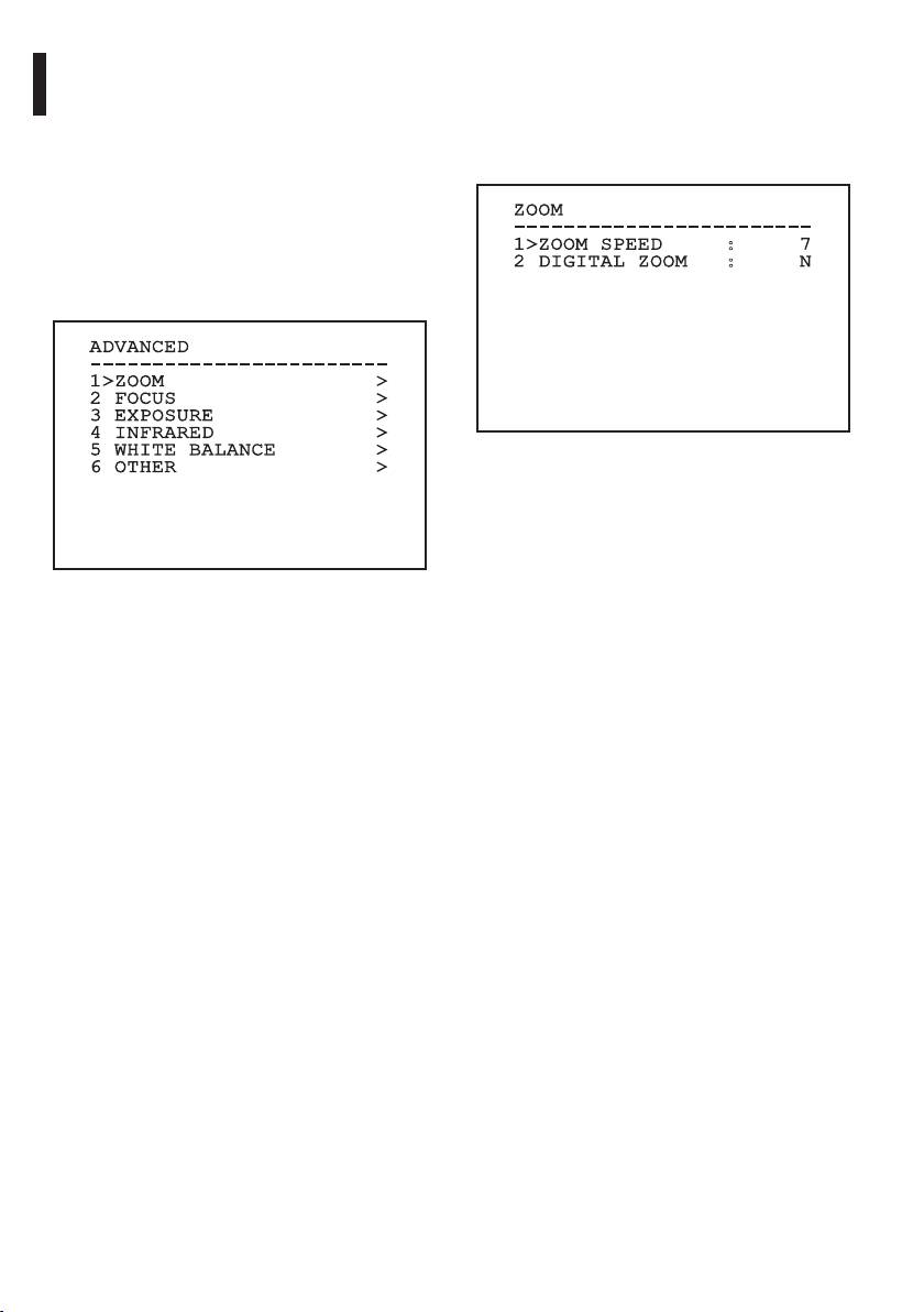
9.6.3.7 Advanced Setting Menu
9.6.3.8 Advanced Setting Menu (Zoom)
This menu is used to congure the SONY module.
1. Zoom Speed: Sets the speed of the zoom. The
speed ranges between 0 (minimum speed) and
1. Zoom: Allows access to the Zoom submenu.
7 (maximum speed).
2. Focus: Allows access to the Focus submenu.
2. Digital Zoom: Enables the digital zoom.
3. Exposure: Allows access to the Exposure.
4. Infrared: Allows access to the Infrared
ZOOM
submenu.
------------------------
5. White Balance: Allows access to the White
1>ZOOM SPEED : 7
2 DIGITAL ZOOM : N
Balance submenu.
6. Other: Allows access to the Other submenu.
EN - English - Instructions manual
ADVANCED
------------------------
1>ZOOM >
2 FOCUS >
3 EXPOSURE >
4 INFRARED >
5 WHITE BALANCE >
Fig. 78
6 OTHER >
Fig. 77
40
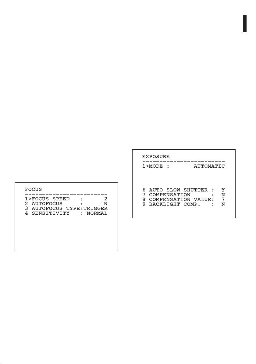
9.6.3.9 Advanced Setting Menu (Focus)
9.6.3.10 Advanced Setting Menu (Exposure)
Once inside the Focus menu it is possible to set the
Once inside the Exposure menu it is possible to set
following parameters:
the following parameters:
Instructions manual - English - EN
1. Focus speed: Sets the speed of the Focus. The
1-5. Mode: Sets the type of exposure control
speed ranges between 0 (minimum speed) and
Automatic, Manual, Shutter, Iris and Bright.
7 (maximum speed).
6. Auto Slowshutter: If enabled, this function
2. Autofocus: Enables or disables the autofocus.
automatically increases the exposure time to
When on, it is to automatically load Autofocus
improve night vision.
at any positioning or movement of the zoom,
7-8. Compensation, Compensation Value: Sets the
depending on the selected operating mode.
exposure compensation.
3. Autofocus Type: Sets the type of Autofocus. The
9. Backlight Compensation: Enables the
possible values are:
Backlight Compensation function. It improves
• Normal: Autofocus is always enabled.
vision of any dark zone in the image.
• Interval: The autofocus function is loaded at
In automatic mode it is possible to enable Backlight
regular intervals of 5 seconds.
compensation. This is a dynamic self-conguration
menu based on the choice made and shows the
• Trigger: Autofocus is loaded at every PTZ
parameters on which it is possible to operate.
movement. This is the recommended
solution.
The chosen exposure operating mode is associated
to all presets.
4. Sensitivity: Sets the level of sensitivity. The
possible values are:
The recommended setting is Automatic.
• Normal: Focusing at the highest possible
speed. This is the recommended solution.
EXPOSURE
------------------------
• Low: Slowed-down focusing. It is useful in
1>MODE : AUTOMATIC
case of dim lighting as it makes the image
more stable.
FOCUS
6 AUTO SLOW SHUTTER : Y
------------------------
7 COMPENSATION : N
1>FOCUS SPEED : 2
8 COMPENSATION VALUE: 7
2 AUTOFOCUS : N
9 BACKLIGHT COMP. : N
3 AUTOFOCUS TYPE:TRIGGER
4 SENSITIVITY : NORMAL
Fig. 80
Fig. 79
41

The following table shows the inserted values with
9.6.3.11 Advanced Setting Menu (Infrared)
the corresponding eects on the SONY module lens.
Once inside the Infrared menu it is possible to set the
CORRESPONDING VALUES/EFFECTS ON THE SONY
following parameters:
MODULE LENS
1. IR Mode: If set to OFF it forces the day mode in
a continuous manner (the switching on of the
illuminator (if present) is carried out by means
of the dusk swtich or by means of the control
on the keyboard); if set to ON it forces the night
mode in a continuous manner; if set to Auto, it
activates the automatic switching of the camera.
Value
Shutter
Iris
Gain
Exposure compen-
sation
2. Night Level: Sets the detection threshold of the
NTSC PAL
light conditions for the night mode switching.
Lower values correspond to lower lighting
EN - English - Instructions manual
0 1/1 1/1 Closed -3db -10,5db
levels.
1 1/2 1/2 F28 0db -9db
2 1/4 1/3 F22 2db -7,5db
3. Night Delay: Sets the detection time of the
darkness conditions, expressed in seconds,
3 1/8 1/6 F19 4db -6db
before switching to night mode.
4 1/15 1/12 F16 6db -4,5db
4. Day Level: Sets the detection threshold of the
5 1/30 1/25 F14 8db -3db
light conditions for the day mode switching.
6 1/60 1/50 F11 10db -1,5db
Lower values correspond to lower lighting
7 1/90 1/75 F9.6 12db 0db
levels.
8 1/100 1/100 F5 14db 1,5db
5. Day Delay: Sets the detection time of the
9 1/125 1/120 F6.8 16db 3db
light conditions, expressed in seconds, before
10 1/180 1/150 F5.6 18db 4.5db
switching to night mode.
11 1/250 1/215 F4.8 20db 6db
12 1/350 1/300 F4 22db 7,5db
13 1/500 1/425 F3.4 24db 9db
14 1/725 1/600 F2.8 26db 10,5db
15 1/1000 1/1000 F2.4 28db
16 1/1500 1/1250 F2
17 1/2000 1/1750 F1.6
18 1/3000 1/2500
19 1/4000 1/3500
20 1/6000 1/6000
21 1/10000 1/10000
Tab. 9
42
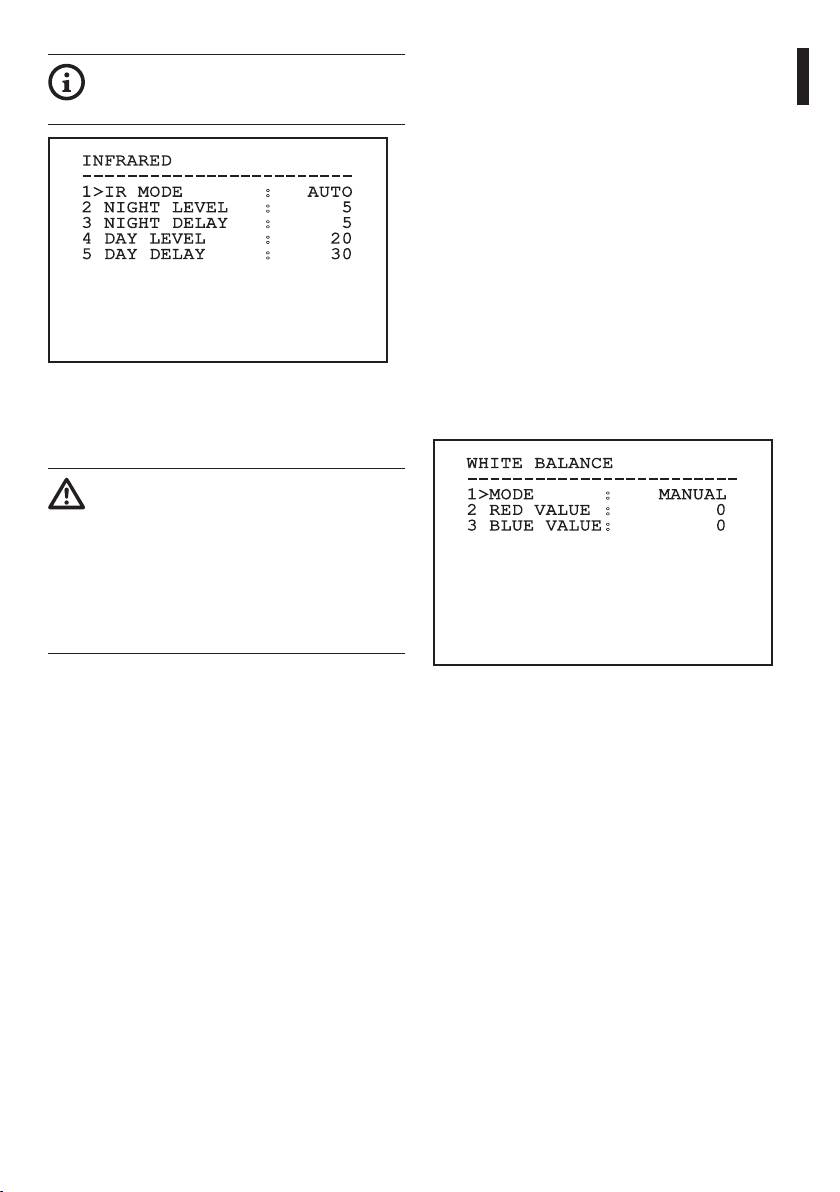
9.6.3.12 Advanced Setting Menu (White
To avoid false switching, we recommend
Balance)
choosing the higher day switching
Once inside the White Balance menu it is possible to
Instructions manual - English - EN
threshold and delay values.
set the following parameters:
1. Mode: Sets the type of control on White
INFRARED
Balance. The possible values are:
------------------------
1>IR MODE : AUTO
• Automatic: Sets automatic white balance.
2 NIGHT LEVEL : 5
This is the recommended setting.
3 NIGHT DELAY : 5
4 DAY LEVEL : 20
• Manual: Enables manual setting of red and
5 DAY DELAY : 30
blue gains.
• Outdoor: Sets xed red and blue gains for
outdoor applications.
• Indoor: Sets xed red and blue gains for
indoor applications.
• ATW: Enables Auto Tracing White Balance.
Fig. 81
2. Red Value: Sets the value of the red gain.
This is a dynamic self-conguration menu based on
3. Blue Value: Sets the value of the blue gain.
the choice made and shows the parameters on which
it is possible to operate.
WHITE BALANCE
------------------------
The automatic Day/Night switching mode
1>MODE : MANUAL
of the module is strongly unadvisable
2 RED VALUE : 0
when swinging is subject to repeated
3 BLUE VALUE: 0
light variations during the night period,
for example during patrol, or due to the
switching on of auxiliary lighting devices.
Those situations can cause numerous
unwanted switching, compromising in this
way the functioning of the module.
Fig. 82
This is a dynamic self-conguration menu based on
the choice made and shows the parameters on which
it is possible to operate.
43
9.6.3.13 Advanced Setting Menu (Other)
• Wind Mode: Sets the movements speed
to adjust them to environments subject to
1. Sharpness: Sets the sharpness value of the
vibrations and/or windblasts.
image.
• High Perf: Establishes that all the movements
2. High Resolution: Enables the High Resolution
are carried out at the maximum possible
function. The output video signal has a higher
speed.
resolution.
• Custom: Signals that the user has manually
3. Wide Dynamic: Enables the Wide Dynamic
selected the movement speeds of the unit.
function. It improves vision when some zones
within the frame are much brighter than others.
2. Oset Pan: The pan & tilt has a mechanically
dened 0° position. The Oset Pan function
4. Stabilizer: Enables the electronic image
allows the denition of a dierent 0° position
stabilization function.
using software.
5. Progressive Scan: Enables the Progressive Scan
EN - English - Instructions manual
3. Manual Control: To access the submenus
function. Gives a more stable image when the
operating the parameters associated with the
Pan & Tilt is connected to a video server.
manual movements of the device.
6. Noise Reduction: Sets the noise reduction
4. Preset: To access the submenus used to to edit
level. Vary the parameter according to the
Preset values.
environmental conditions to obtain a higher
contrast image.
5. Patrol: To access the submenus used to edit
Patrol values.
OTHER
6. Autopan: To access the submenus used to edit
------------------------
Autopan values.
1 SHARPNESS : 6
7. Motions Recall: To access the submenu which
2 HIGH RESOLUTION : N
3 WIDE DYNAMIC : OFF
manages automatic load of the movements.
4 STABILIZER : N
8. Advanced: Allows access to the advanced
5 PROGRESSIVE SCAN: N
settings submenu.
6 NOISE REDUCTION : 2
MOTION
------------------------
1>CONFIG. : STANDARD
2 OFFSET PAN: + 0.00
3 MANUAL CONTROL >
Fig. 83
4 PRESET >
5 PATROL >
9.6.4 Movement Menu
6 AUTOPAN >
7 MOTIONS RECALL >
1. Conguration: Sets one of the default
8 ADVANCED >
congurations of the pan & tilt.
• Standard: Sets the standard movement
speed.
• Low Speed: Sets the Low Speed mode that
Fig. 84
slows down all pan & tilt operating speeds.
44
9.6.4.1 Manual Control Menu
9.6.4.2 Manual Control Menu (Limits)
1. Maximum Speed: Sets the maximum manual
Once inside the Limits menu it is possible to set the
speed.
following parameters:
Instructions manual - English - EN
2. Fast Mode: Enables the Fast mode. When
1. Pan Limits: Enables the limits of Pan.
enabled, this option is used to move fastly the
2. Pan Start: Sets the start limit of Pan.
pan & tilt by moving the joystick to the limit
3. Pan End: Sets the end limit of Pan.
stop.
4. Tilt Limits: Enables the limits of Tilt.
3. Speed With Zoom: Enables the option Speed
with ZOOM. When enabled, this parameter
5. Tilt Start: Sets the start limit of Tilt.
automatically slows down the PAN & TILT speed,
6. Tilt End: Sets the end limit of Tilt.
based on the ZOOM factor.
4. Tilt factor: Sets the reduction factor of the tilt
LIMITS
axis manual speed.
------------------------
1>PAN LIMITS : N
5. Autoip: Enables the autoip function (i.e.
2 PAN START : + 0.00
when the tilt reaches the end of the stroke, it
3 PAN END : + 0.00
automatically rotates the pan & tilt by 180°),
4 TILT LIMITD : N
making it easier to follow the objects along
5 TILT START : + 0.00
6 TILT END : + 0.00
corridors or roads.
6. Movement Limits: To access the Limits menu.
Manual Control
------------------------
1>MAXIMUM SPEED :100.0
Fig. 86
2 FAST MODE : Y
3 VEL. WITH ZOOM : N
9.6.4.3 Preset Menu
4 TILT SCALE FACT.: 2
5 AUTOFLIP : Y
1. Edit Preset: Allows access to Edit Preset menu.
6 MOVEMENT LIMITS >
2. Utilities Conguration: Allows access to
Utilities Conguration menu.
PRESET
------------------------
1>EDIT PRESET >
Fig. 85
2 PRESET UTILITIES >
Fig. 87
45
9.6.4.4 Preset Menu (Edit Preset)
9.6.4.5 Preset Menu (Preset Utilities)
Once inside the Edit Preset menu it is possible to set
Once inside the Utilities Conguration menu it is
the following parameters:
possible to set the following parameters:
1. Number: The Preset number to be edited.
1. Daytime A.Focus: Enables the use of the
autofocus when loading the preset in daytime
2. Enabling: Enabling preset.
mode. To guarantee fast and accurate focusing
3. Pan: Pan position in degrees.
of the image, disable the automatic focus.
4. Tilt: Tilt position in degrees.
2. Night-time A.Focus: Enables the use of the
5. Zoom: Zoom position.
autofocus when loading the preset in night-time
6. Focus: Daytime and night-time position of the
mode. We advise enabling the automatic focus
focus.
when the pan & tilt is tted with an infrared
illuminator, as the focal point varies depending
7. Speed: The speed at which the position is
on whether the light is visible or infrared.
EN - English - Instructions manual
reached when preset is recalled from the Patrol
and Scan function.
3. Scan Speed: This is the reference speed used
when a preset position is recalled by the Scan
8. Pause: Sets the dwell time in seconds before
function.
starting the next movement in Patrol.
4. Default Speed: Changes the default speed
9. Text: The text that is displayed when the preset
of the Presets. This value is used based on the
position is reached.
function Set Speed? to assign the same speed to
all Presets .
EDIT PRESET
5. Default Dwell time: Changes the default pause
------------------------
1>NR. : 1
of the Presets. This value is used based on the
2 ON : N
function Set Dwell Time? to assign all Presets the
3 PAN :+ 0.00
same pause time.
4 TILT :+ 0.00
5 ZOOM : 0
6. Set Speed: To assign all Presets the same default
6 FOCUS: 4096 - 5600
speed.
7 SPEED: 100.0
7. Set Dwell time: To assign all Presets the same
8 PAUSE: 1
9 TEXT : Text 001
default dwell time.
PRESET UTILITIES
------------------------
Fig. 88
1>AUTOFOCUS DAY : N
2 AUTOFOCUS NIGHT: Y
From the menu it is possible to directly store the
3 SCAN SPEED : 200.0
preset by sending the Iris Close command that
4 DEFAULT SPEED : 100.0
enables the pan & tilt movements.
5 DEFAULT DWELL : 3
6 SET SPEED?
7 SET PAUSE?
Fig. 89
46
9.6.4.6 Patrol Menu
9.6.4.8 Motion Recall Menu
1. First Preset: Sets the rst preset of the Patrol
It is possibile to set the unit so that, after a given
sequence.
inactivity interval, it automatically carries out the
Instructions manual - English - EN
movement function set by the operator.
2. Last Preset: Sets the last preset of the Patrol
sequence.
From the menu it is possible to set the following
parameters:
3. Random Mode: Enables random execution. The
sequence is re-calculated on a continuous basis.
1. Movement Type: Choice of type of movement
to be loaded (None, Home, Autopan, Patrol, Tour
1, Tour 2, Tour 3).
PATROL
------------------------
2. Movement Delay: The time (in seconds) that
1>FIRST PRESET : 1
needs to elapse from the state of inactivity of
2 LAST PRESET : 250
the Joystick before loading the set movement.
3 RANDOM MODE : N
MOTION RECALL
------------------------
1>MOVEMENT TYPE : NONE
2 MOVEMENT DELAY: 60
Fig. 90
9.6.4.7 Autopan Menu
1. Preset Outward Movement: Sets the initial
position of the Autopan.
2. Preset Return Movement: Sets the nal
Fig. 92
position of the Autopan.
3. Outward Movement Speed: Sets the speed of
the outward movement of the Autopan.
4. Return Speed: Sets the speed of the return of
the Autopan.
AUTO-PAN
------------------------
1>PRESET OUTWARD: 1
2 PRESET RETURN : 2
3 OUTWARD SPEED : 20.0
4 RETURN SPEED :100.0
Fig. 91
47
9.6.4.9 Advanced Menu
9.6.5 Display Menu
1. Static Control: Enables control of the position
1. PTZ Positions: If not on OFF, it is used to select
only when the pan & tilt is stopped
how the Pan, Tilt and Zoom positions are
displayed on the screen. It is possible to select
2. Dynamic Control: Enables control of the
timed (1 S, 3 S and 5 S) or constant (CONST)
position only when the pan & tilt is moving
display.
3. Cyclic Homing: If other than zero, it sets a new
2. Preset Name: If not on OFF, it is used to select
homing procedure after the specied number of
how the text associated with the last-reached
hours.
Preset position is displayed on the screen. It is
4. Economy Mode: Reduces the motor toque
possibile to select timed (1 S, 3 S and 5 S) or a
when the pan & tilt is not moving. Do not enable
constant (CONST) display.
in presence of strong wind or vibrations.
3. Areas Name: If not on OFF, it is used to select
EN - English - Instructions manual
how the texts associated with active areas are
ADVANCED
displayed. It is possibile to select timed (1 S, 3 S
------------------------
and 5 S) or constant (CONST) display.
1>STATIC CONTROL : Y
2 DYNAMIC CONTROL : Y
4. Pan & Tilt ID: If not on OFF, it shows the ID of
3 CYCLIC HOMING : 0
the pan & tilt.
4 ECO MODE : Y
5. Received Commands: If not on OFF, it is used
to select how the received serial commands are
displayed. It is possibile to select timed (1 S, 3 S
and 5 S) or constant (CONST) display.
6. Horizontal Delta: This moves the menu texts
horizontally, for better centring.
Fig. 93
7. Vertical Delta: This moves the menu texts
vertically for better.
DISPLAY
------------------------
1>PTZ POSITIONS : 1 S
2 PRESET NAME : 3 S
3 AREAS NAME : OFF
4 UNIT ID :CONST
5 RECEIVED COMMAND:CONST
HORIZONTAL DELTA: 3
VERTICAL DELTA : 3
Fig. 94
48
9.6.6 Options Menu
From the Alarms menu it is possible to access one of
the menus (Alarms 1-5) to edit the alarms parameters.
1. Ceiling Mount: When this mode is enabled the
image and the movements controls are turned
From these menus it is possible to set the following
Instructions manual - English - EN
upsidedown.
values:
2. Alarms: Allows access to the Alarms menu.
1. Type: Set the type of contact: normally closed
(N.C.) or normally open (N.O.).
3. Washer: Allows access to the Washer menu.
2. Action: The type of action (Scan, Patrol,
Autopan, Tour 1, Tour 2 and Tour 3) carried out
OPTION
by the unit when the alarm triggers. If O is
------------------------
1>CEILING MOUNT :N
selected, the alarm is disabled.
2 ALARMS >
3. Number: The preset to be reached when the
3 WASHER >
alarm’s type of action is Scan.
4. Text: The message that is displayed when the
alarm is active.
ALARM 1
------------------------
1>TYPE :N.C.
2 ACT. :SCAN
Fig. 95
3 NR. : 1
4 TEXT :ALARM 1
9.6.6.1 Alarms Menu
1-5. Alarms 1-5: Allow access to the menus from
which it is possible to set the parameters of
Alarms 1 to 5.
6. Alarms State: Allows access to the Alarms State
menu.
Fig. 97
ALARM
This is a dynamic self-conguration menu based on
------------------------
the choice made and shows the parameters on which
1>ALARM 1 >
2 ALARM 2 >
it is possible to operate.
3 ALARM 3 >
From the Alarms menu it is possible to access the
4 ALARM 4 >
Alarms State menu where the state of alarms inputs
5 ALARME 5 >
6 ALARMS STATE >
is displayed (CLOSED, contact closed, OPEN, contact
open).
ALARMS STATE
------------------------
ALARM 1 CLOSED
ALARM 2 OPEN
Fig. 96
ALLARME 3 CLOSED
ALLARME 4 CLOSED
If the IR illuminator is tted, alarm 5 is
ALLARME 5 CLOSED
reserved for the external dusk switch and
therefore alarm 5 will not be displayed on
the screen.
Fig. 98
49
9.6.7 Washer Menu
9.6.8 Default Menu
The unit oers the possibility to use a wiper and to
1. Delete Setup: Resets all the parameters except
operate a pump to clean the glass.
the Presets.
To congure the Washer put the lens of the camera in
2. Delete Preset: Deletes all previously stored
front of the nozzle of the Washer.
presets.
Save a preset (XY) that identies this position; the
preset will be recalled by the pan & tilt when the
DEFAULT
WASHER function is enabled.
------------------------
1>DELETE SETUP?
From the menu, set the following parameters:
2 DELETE PRESET?
1. Enable: Enables the Washer function.
2. Nozzle preset: Enter the preset number (XY)
corresponding to the nozzle.
EN - English - Instructions manual
3. Wiper On Delay: Sets the interval between the
enabling of the pump and that of the wiper.
4. Washing length: Sets the length of the
brushing.
5. Wiper O Delay: Sets the length of the
Fig. 100
brushing without water.
The above mentioned operations cause the
loss of all previously stored data (i.g. Preset,
WASHER
Patrol, Autopan, Home…).
------------------------
1>ENABLE : N
2 NOZZLE PRESET : 1
9.6.9 Info Menu
3 WIPER-ON DELAY : 5
The menu is used to check the conguration of the
4 WASHING DURATION : 10
device and the installed rmware version.
5 WIPER-OFF DELAY : 5
INFO
------------------------
Address: 1
Protocol : MACRO
RS485-1:38400 N81 RX
RS485-2:38400 N81 REPEAT
Fig. 99
FW: 0a (Apr 14 2009)
HW: 000-0000
The enabling of the Washer function
Camera : 36x
reserves the use of Relay 2 to the switching
PC: MPX1PVW0000A
SN: 109032220029
on of the pump and does not allow the
association of Relay 2 with an alarm.
Fig. 101
50
9.6.10 Thermal Camera Menu
5. Gain control: Allows access to the gain control
management submenu.
1. Control: Sets the type of control on the thermal
camera.
6. ROI Setup: Allows access to the ROI
Instructions manual - English - EN
management submenu.
• Internal: The camera conguration is
managed by the pan & tilt.
7. Thermal Analysis: Allows access to the thermal
analysis management submenu.
• External: The camera conguration is
managed through the RS485-3 serial line
8. Status: Allows access to the submenu
(only for models with double camera)
containing the technical features of the thermal
camera.
2. Conguration: To set one of the preset
congurations of the thermal camera.
THERMAL CAMERA
• Standard: Sets the standard conguration of
------------------------
the thermal camera.
1>CONTROL : INTERNAL
2 CONFIG. : STANDARD
• High Gain: Sets the conguration for a
3 FLAT FIELD CORRECTION>
higher-resolution image.
4 VIDEO SETUP >
• Isotherm: Sets the conguration for
5 GAIN CONTROL >
6 ROI SETUP >
highlighting objects within a given
7 THERMAL ANALYSIS >
temperature range (9.6.10.8 Thermal Analysis
8 STATUS >
Menu (Isotherm), page56).
• Custom: Signals that the operator has
manually chosen the conguration of the
thermal camera.
Fig. 102
3. Flat Field Correction: Allows access to the Flat
Field correction management submenu.
4. Video Setup: Allows access to the video
conguration management submenu.
51
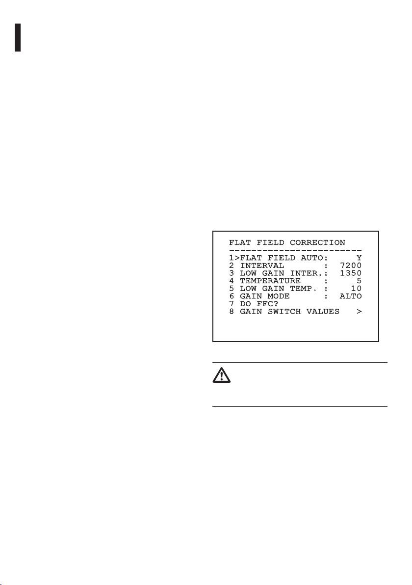
9.6.10.1 Flat Field Correction Menu
6. Gain mode: Allows the setting of dynamic gain
range type:
The thermal camera is tted with an internal
mechanism which periodically improves the quality
• High: This setting aims to maximize the
of the images called Flat Field Correction (FFC). The
contrast and is especially suitable for
parameters which manage this function are:
applications which carry out the video
analysis of images.
1. Flat Field Auto: Enables the automatic
or manual Flat Field correction. When the
• Low: This setting increases the dynamic range
automatic correction is enabled, the camera
of the image and diminishes the contrast. It is
carries out a FFC after a given time or
especially suitable for identifying the hottest
temperature change. Vice versa, when the
elements in an image.
manual correction is set, the FFC operations are
• Auto: This setting allows the camera to switch
carried out when requested by the operator. We
between High and Low modes depending on
advise setting the manual correction at all times.
the type of image currently being displayed.
EN - English - Instructions manual
2. Interval: Sets the time that has to elapse before
The parameters in the Gain Change Values
carrying out a FFC when the dynamic gain range
menu are used to change the behaviour of
is High. The time interval is indicated in frames
this mode (9.6.10.2 Flat Field Correction Menu
(33ms for NTSC and 40ms for PAL).
(Gain Switch Values), page53).
3. Low Gain Interval: Sets the time that has to
7. Do FFC: Carries out a FFC.
elapse before carrying out a FFC when the
8. Gain Switch Values: Allows access to the Gain
dynamic gain range is Low. The time interval is
Switch Values submenu.
indicated in frames (33ms for NTSC and 40ms for
PAL).
FLAT FIELD CORRECTION
4. Temperature: Sets the temperature change
------------------------
after which a FFC has to be carried out when the
1>FLAT FIELD AUTO: Y
2 INTERVAL : 7200
dynamic gain range is High. The temperature
3 LOW GAIN INTER.: 1350
change is indicated in 0.1°C intervals.
4 TEMPERATURE : 5
5. Low Gain Temperature: Sets the temperature
5 LOW GAIN TEMP. : 10
6 GAIN MODE : ALTO
interval after which a FFC has to be carried
7 DO FFC?
out when the dynamic gain range is Low.
8 GAIN SWITCH VALUES >
The temperature change is indicated in 0.1°C
intervals.
Fig. 103
We recommend that you do not change
the default values which have been set
to guarantee high quality images in any
operating condition.
52
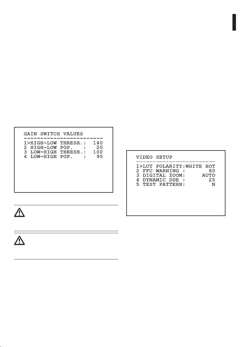
9.6.10.2 Flat Field Correction Menu (Gain
9.6.10.3 Video Setup Menu
Switch Values)
Once inside the Video Conguration menu it is
Once inside the Gain Switch Values menu it is
possible to set one of the following parameters:
Instructions manual - English - EN
possible to set one of the following parameters:
1. Lut polarity: Sets the hue of the image shot by
1. High-Low Threshold: Sets the temperature
the thermal camera.
threshold used by the High-Low Population
2. FFC Warning: Sets the interval for which a
parameter to force the switching in Low Gain
coloured square is displayed on the upper right
mode. The value is indicated in degrees Celsius.
side of the video when a FFC is about to be
2. High-Low Population: Sets the minimum pixel
carried out. The interval is indicated in frames
percentage above which the switching in Low
(33ms for NTSC and 40ms for PAL). A value lower
Gain mode is carried out.
than 15 frames automatically disables the alert.
3. Low-High Threshold: Sets the temperature
3. Digital Zoom: Sets the type of zoom to be
threshold used by the Low-High Population
applied to the video signal (OFF, Auto, 2x, 4x).
parameter to force the switching in High Gain
When using the Auto mode, the zoom of the
mode. The value is indicated in degrees Celsius.
thermal camera automatically adjusts to that of
the SONY module.
4. Low-High Population: Sets the minimum pixel
percentage above which the switching in High
4. Dynamic DDE: Sets the value of the DDE lter,
Gain mode is carried out.
used to improve the sharpness of outline.
Typical values range from 17 and 25. Value 17
disables the lter.
GAIN SWITCH VALUES
------------------------
5. Test Pattern: Enables the pattern test to check
1>HIGH-LOW THRESH.: 140
the camera electronics.
2 HIGH-LOW POP. : 20
3 LOW-HIGH THRESH.: 100
4 LOW-HIGH POP. : 95
VIDEO SETUP
------------------------
1>LUT POLARITY:WHITE HOT
2 FFC WARNING : 60
3 DIGITAL ZOOM: AUTO
4 DYNAMIC DDE : 25
5 TEST PATTERN: N
Fig. 104
We recommend that you do not change
the default values which have been set
to guarantee high quality images in any
Fig. 105
operating condition.
The settings of the Gain Change Values
Menu are eective only if the Gain
mode was set to Auto (9.6.10.1 Flat Field
Correction Menu, page52).
53
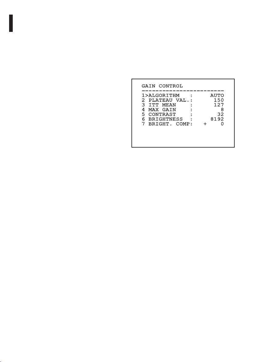
9.6.10.4 Gain Control Menu
2. Plateau value: Sets the maximum pixel value
which can be found in a grey scale.
Once inside the Gain Control Conguration menu it is
possible to set one of the following parameters:
3. ITT Mean: Sets the mean point on a grey scale.
1. Algorithm: Sets the type of automatic gain
4. Max Gain: Sets the maximum gain of the AGC.
control (AGC) to optimize the image. It is
5. Contrast: Sets the contrast level of the image.
possible to choose between the following
6. Brightness: Sets the brightness level of the
algorithms:
image.
• Automatic: Automatically sets the
7. Brightness Compensation: Sets the brightness
contrast and brightness of the image
compensation level of the image.
when environmental conditions change by
equalizing the grey scale histogram. The
image can be modied by changing the value
GAIN CONTROL
------------------------
of the ITT Mean, Max Gain and Plateau Value
EN - English - Instructions manual
1>ALGORITHM : AUTO
parameters. This is the default algorithm
2 PLATEAU VAL.: 150
and it is recommended for normal use of the
3 ITT MEAN : 127
thermal camera.
4 MAX GAIN : 8
5 CONTRAST : 32
• Once Bright: The set brightness level
6 BRIGHTNESS : 8192
represents the mean of the brightness values
7 BRIGHT. COMP: + 0
of the image when this parameter is selected.
The image can be modied by changing the
value of the Contrast parameter.
• Auto Bright: The set brightness level
represents the mean of the brightness values.
Fig. 106
Such level is updated in real-time. The image
This is a dynamic self-conguration menu based on
can be modied by changing the values of
the choice made and shows the parameters on which
the Contrast and Compensation parameters.
it is possible to operate.
• Manual: The contrast and brightness levels
are manually set by the user.
• Linear Histogram: Contrast and brightness
of the image are optimized using one linear
transfer function. The image can be modied
by changing the values of the ITT Mean and
Max Gain parameters.
54
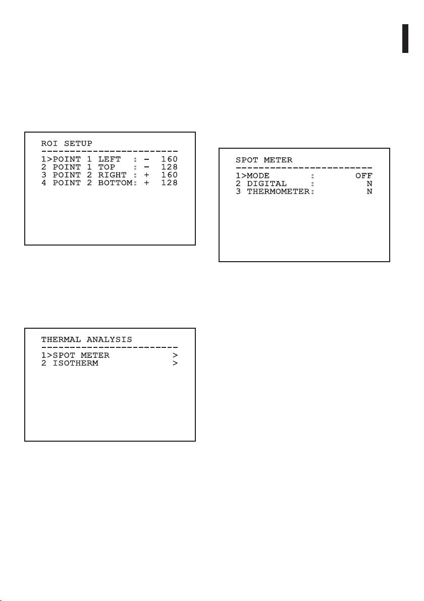
9.6.10.5 ROI Setup Menu
9.6.10.7 Thermal Analysis Menu (Spot Meter)
Once inside the ROI Conguration Menu it is
Once inside the Point Measurement menu it is
possible to change the region of interest (ROI) used
possible to set one of the following parameters:
Instructions manual - English - EN
by the AGC algorithm to calculate the contrast and
1. Mode: Enables the visualization of the taken
brightness levels of the image.
temperature from the 4 pixels to the centre of
1. Point 1 Left: Sets the left limit of the ROI.
the image (in degrees Celsius or Fahrenheit). The
OFF option disables the visualization.
2. Point 1 Top: Sets the upper limit of the ROI.
2. Digital: Enables the visualization of the relative
3. Point 2 Right: Sets the right limit of the ROI.
symbol on the display.
4. Point 2 Bottom: Sets the lower limit of the ROI.
3. Thermometer: Enables the visualization of the
relative symbol on the display.
ROI SETUP
------------------------
1>POINT 1 LEFT : - 160
SPOT METER
2 POINT 1 TOP : - 128
------------------------
3 POINT 2 RIGHT : + 160
1>MODE : OFF
4 POINT 2 BOTTOM: + 128
2 DIGITAL : N
3 THERMOMETER: N
Fig. 107
9.6.10.6 Thermal Analysis Menu
Fig. 109
1. Spot Meter: Allows access to the point
measurement conguration submenu.
2. Isotherm: Allows access to the isotherm
management submenu.
THERMAL ANALYSIS
------------------------
1>SPOT METER >
2 ISOTHERM >
Fig. 108
55
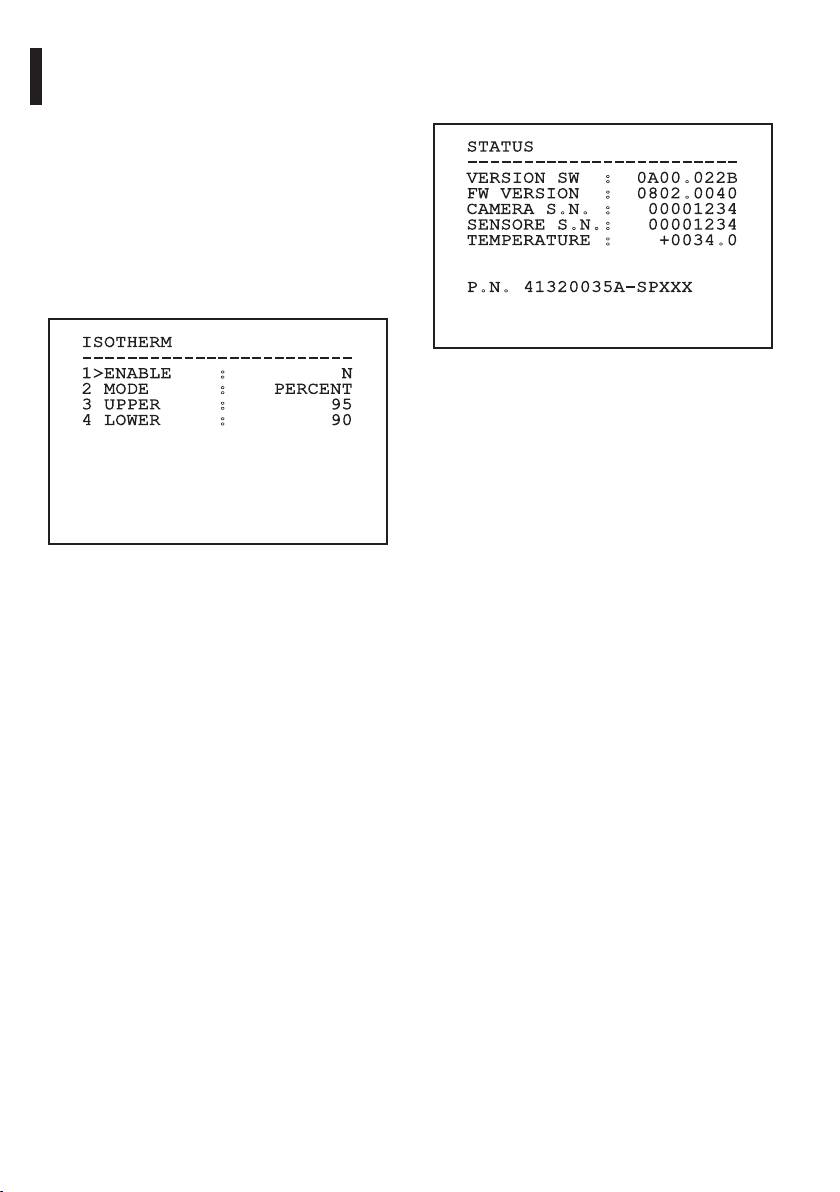
9.6.10.8 Thermal Analysis Menu (Isotherm)
9.6.10.9 Status Menu
Once inside the Isotherm menu it is possible to
Once inside the Status menu it is possible to learn the
enable a special colouring for objects included within
technical features of the thermal camera.
the set temperature interval. The parameters which
manage this function are:
STATUS
1. Enable: Enables the Isotherm function.
------------------------
VERSION SW : 0A00.022B
2. Mode: Selects the way in which the interval is
FW VERSION : 0802.0040
indicated (in percentage or in degrees Celsius).
CAMERA S.N. : 00001234
SENSORE S.N.: 00001234
3. Upper: Sets the upper limit of the Isotherm
TEMPERATURE : +0034.0
function.
4. Lower: Sets the lower limit of the Isotherm
P.N. 41320035A-SPXXX
function.
EN - English - Instructions manual
ISOTHERM
------------------------
1>ENABLE : N
Fig. 111
2 MODE : PERCENT
3 UPPER : 95
4 LOWER : 90
Fig. 110
This is a dynamic self-conguration menu based on
the choice made and shows the parameters on which
it is possible to operate.
56
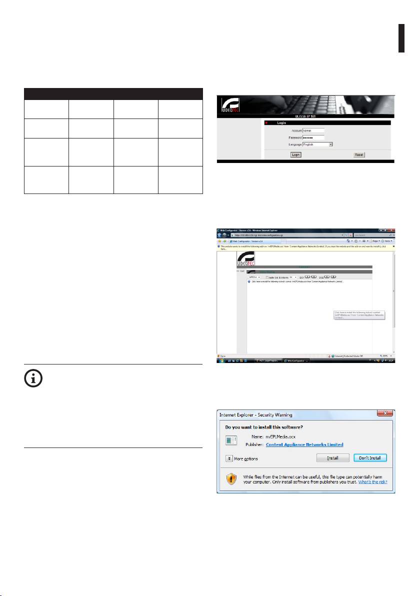
Enter address 192.168.0.100. you will have to log in
9.7 IP Board Conguration
with a password.
9.7.1 Minimum system requirements
The default account name is: Admin (with a capital A).
Instructions manual - English - EN
Choose one of the following congurations,
The default password is: 123456
according to the number of channels to be
When making the settings for the rst time, insert the
controlled.
default account name and password.
CHANNELS CPU MEM HDD
16 Intel Core 2
1GB 250GB
Duo 2.4 GHz
32 Intel Core 2
2GB 250GB
Duo 2.66 GHz
49 Intel Core 2
4GB 250GB
Quad 2.66
GHz
64 Intel Core 2
4GB 250GB
Fig. 112
Quad 2.66
GHz
When installing for the rst time, it will be necessary
to install OCX control in order to have a correct video
Tab. 10
display and then conrm the settings in the following
pop-up menu.
9.7.2 Conguration procedure
Once the pan & tilt has been preset and congured,
start conguring the IP parameters (6.1.8 Connection
of the ethernet cable, page22).
The IP address of the various units should be
congured using a PC with a Microsoft Windows Xp®
service pack 2 or Microsoft Windows Vista® (Business
Edition or Enterprise Edition) OS and Microsoft
Internet Explorer® software.
Set the IP address of the PC as 192.168.0.1 (or
192.168.0.2 etc.).
To congure the unit, connect it physically to the
LAN, power it and run the browser Microsoft Internet
Explorer® version 6.0 or above.
To set the IP address of the various units,
Fig. 113
power them, taking care to connect them
When you have pressed OK/Enter in the pop-up
one at a time to the LAN (switch/hub).
menu, the following window will appear.
Congure the unit and insert the settings
for at least the IP address and host name.
When the unit has all the desired settings,
connect the ethernet cable and go on to
congure the next unit.
Fig. 114
57
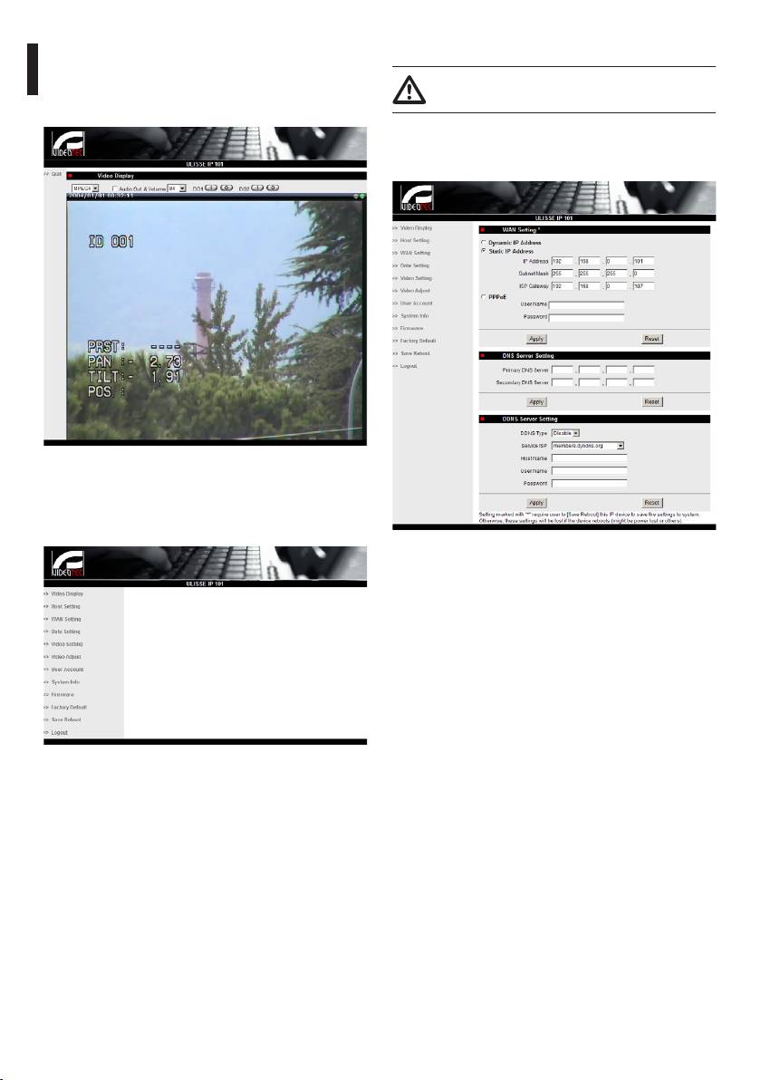
Continue by pressing the Install button. You carry out
9.7.2.1 WAN setting
this procedure once and only once for each PC that is
Keep the account and the password in a
to have access to the device in the network.
secure place.
The Live Video window will then appear.
Next, set the static IP address, which is used to
gain access to the unit that is to be congured. For
example, set a static IP and address 192.168.0.101.
EN - English - Instructions manual
Fig. 115
To make the parameter settings, click on the Quit
button next to the video display. The general
parameter setting menu will then appear.
Fig. 117
Next, click on Apply and then click on Save & Reboot.
Wait about 30 seconds, until the settings have been
saved. Re-connect to the modied address (e.g.
192.168.0.101), inserting the Account Name and
Password (use the default settings if they have not
been changed).
Fig. 116
58
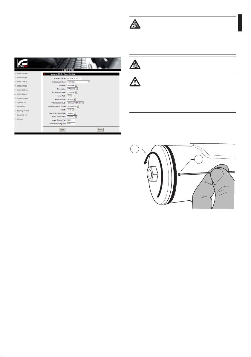
Then edit the other parameters, for example:
Before doing any technical work or
• Date Setting: To set date and time.
maintenance on the device, make sure
Instructions manual - English - EN
• Video Setting: To change resolution (720x576,
that potentially explosive atmosphere is
640x480, 352x288, 176x144) bit rate (setting
not present. To reduce the risk of ignition
between 28kbit and 3 Mbit).
don’t open the device when a potentially
For telemetry, leave the default settings.
explosive atmosphere is present.
Before starting any operation, make sure
the power supply is disconnected.
In extreme cases, when you have forgotten
the password for accessing the unit via the
browser, you can also restore the factory
setting by connecting the reset switch
board situated inside the package and
pressing the Reset button.
For Reset to take eect, you have to disconnect the
power supply to the pan & tilt.
Remove the hexagon set screw and unscrew the
treaded cover of the junction box.
Fig. 118
After all the settings have been inserted, remember
02
to Save & Reboot, so that the changes will take eect.
01
• Factory Default: Used to restore default factory
settings.
Fig. 119
59
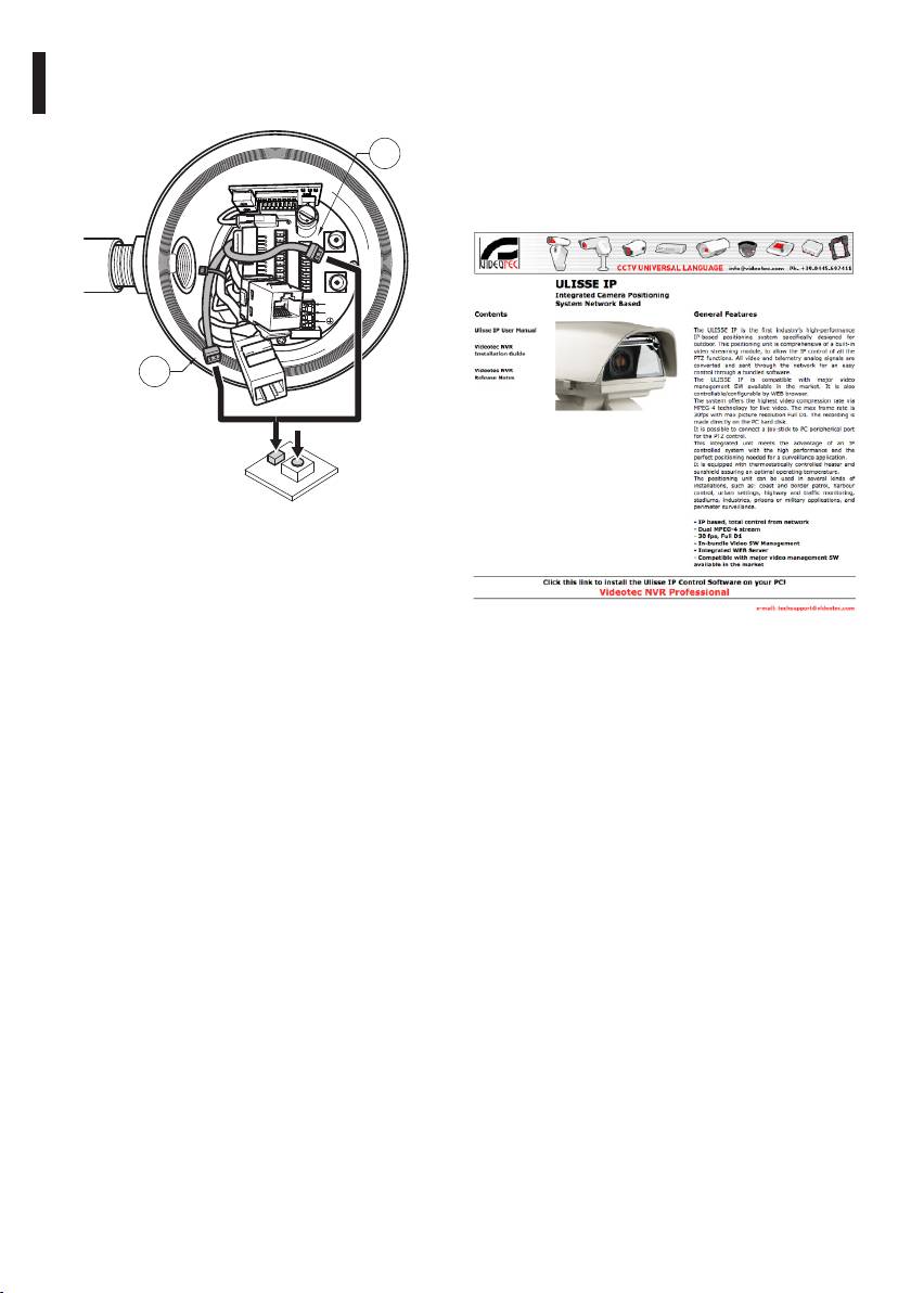
Plug the cable (01), situated in the junction box, in
9.7.3 Installing the NVR software
the reset switch board. Keep pressed the reset button
A CD-ROM containing display and control software is
while reconnecting the power supply.
supplied for controlling the various units. Follow the
instructions below to install the software correctly.
02
Insert the CD-ROM in the player, and after a few
seconds the following introductory display will
F
appear.
U
S
E
J8
J3
FUS2
VIDEO - 1
J2
RL2
RL2
J9
J6
RL1
A
RL1
B
COM
AL5
A
RS485
AL4
B
VIDEO - 2
AL3
GND
AL2
W
J7
AL1
GND
FUS1
VAR1
AC
IN
J1
F
U
S
E
L
N
VAR2
VAR3
100nMBW3
EN - English - Instructions manual
01
Fig. 120
Keep the button pressed for 5 seconds and then
release it. The factory default values of the unit are
restored.
Repeat the procedure with the cable of the thermal
Fig. 121
camera(02), if present.
Select Videotec NVR Professional and follow the
When nished change the O-ring gasket (new O-ring
instructions that appear on the screen.
is in the package), lubricate it and the threads with
technical vaseline oil.
When you have completed installation, and the pan
& tilts have been congured as appropriate (see
Screw the threaded cover of the junction box and
previous section), you can run the NVR software to
x the hexagon set screw proceeding in the reverse
make the initial settings for the system.
order as shown in Fig. 119, page59.
Start the Activemonitor software.
You will have to insert the usual User Name (default:
Admin) and Password (default: 123456)
60
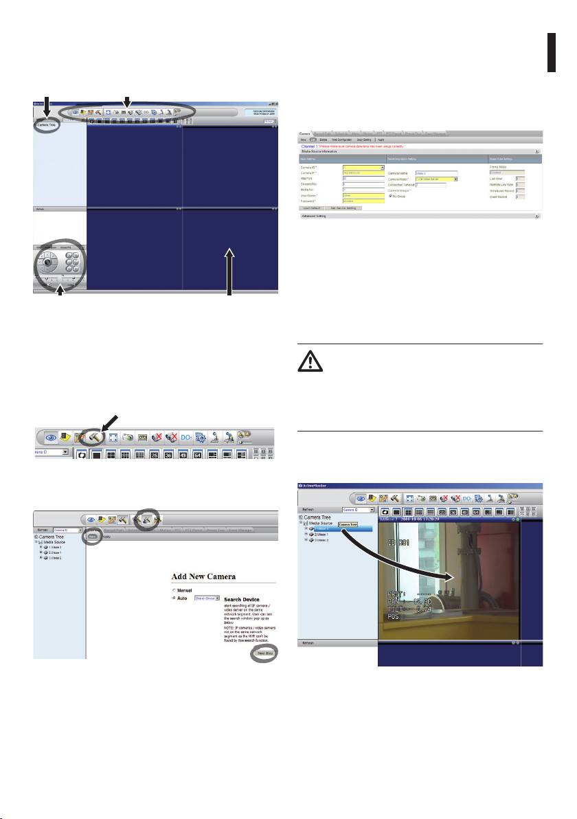
The rst time you run the program, the following
When setting up manually, it is essential (as in
display will appear, with an empty camera list
automatic setup, apart from the IP address) to set the
(Camera Tree).
items marked by an asterisk, i.e.
Instructions manual - English - EN
Camera ID: Consecutively, 1, 2, 3 etc.
Camera tree Tool bar
Camera IP: E.g. 192.168.0.102
Camera Model: Select 1-CH Video Server
Fig. 125
Set the name that will appear in the Camera Tree:
Camera Name: P&T 2 Example
On completion, click on Apply and wait until the
Manual control
Live Video
settings have been saved.
panel
Repeat the procedure for all the other devices
present in the system.
Fig. 122
At this point you need to add the various devices
On completion of this stage, you should
present in the system. Click on the Setup button in
close the NVR program and re-start it so
the control bar.
that the changes take eect. When the
program is restarted, the Camera Tree
Setup button
should contain a list of the units in the
system for which settings have been made.
From the Media Source list, drag & drop the rst unit
into one of the blue windows, and the live video
image should appear.
Fig. 123
Then click on Setup Camera.
Fig. 124
Fig. 126 Example of drag & drop.
Insert the settings manually if you know the IP
Repeat the procedure for the other units.
addresses of the various units present, otherwise do
an automatic setup, which will identify the various
units.
61
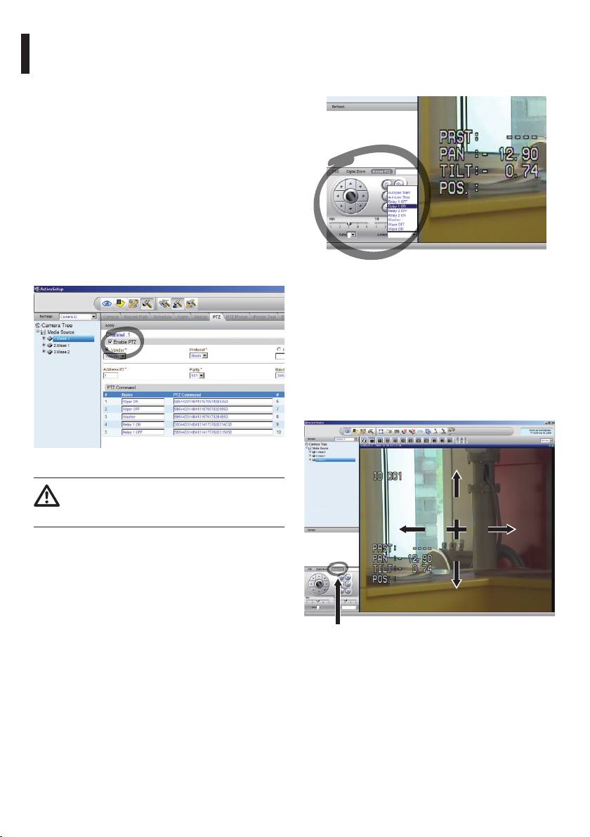
9.7.3.1 Controlling PTZ movements
To control a unit via the control panel, select the unit
to be controlled by clicking with the mouse on the
To set movement control via the control panel or via
corresponding video window, and then operate from
mouse, proceed as follows:
the control panel .
Select the Setup / Setup Camera menu and select the
PTZ tab.
Select the rst unit, or the one you want to congure,
from the Media Source list.
Check the Enable PTZ box.
Click on Apply.
This will automatically set the VIDEOTEC Macro
protocol at 38400 baud.
EN - English - Instructions manual
Repeat the procedure for the other units to be
controlled, directly from the PTZ setup menu ; just
select the other units present in the Media Source list
of the Camera Tree menu, one at a time, and check
Enable PTZ, then click on Apply.
Fig. 128
It is possible to set 5 dierent speeds for pan and tilt
and it is also possible to enable advanced functions
using the Action menu (which contains, for example,
the Autopan, Start, Stop commands etc.). If you want
to control the PTZ using the mouse, directly from
the video window, check Mouse PTZ in the control
panel. You can then use the mouse to control both
movements and zoom (Zoom + and Zoom - are
situated in the centre).
Fig. 127
When the unit settings have been inserted,
quit the NVR programm and re-start it so
that all the changes will be saved.
Mouse PTZ
Fig. 129
62
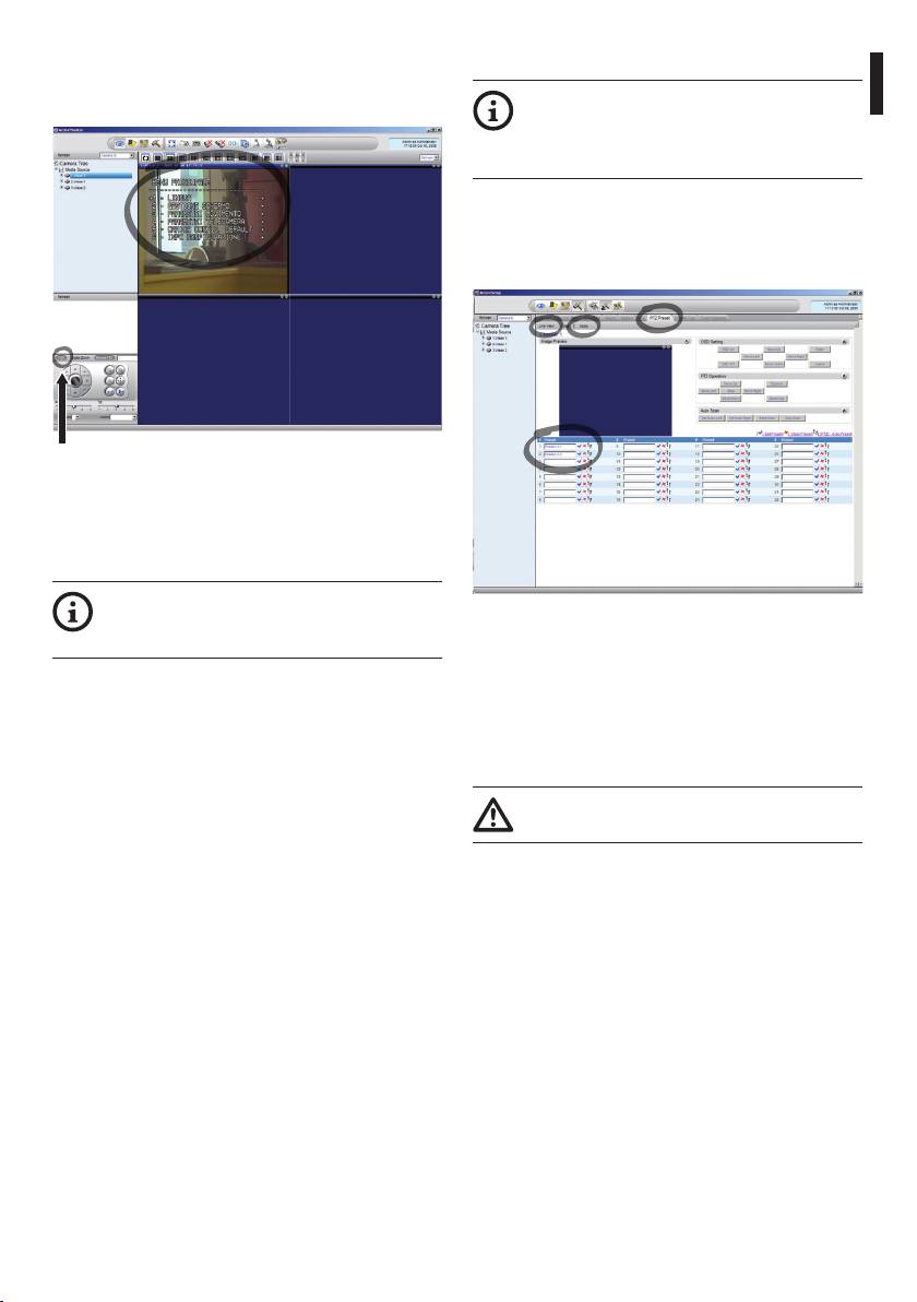
To set the conguration parameters of the pan & tilt
9.7.3.2 Preset and load positions
by means of OSM, enable the corresponding function
Before making these settings, we
using the control panel.
Instructions manual - English - EN
recommend enabling Mouse PTZ control,
so that it is easier to move around in the
position to be saved.
Enter the Setup / Setup Camera Menu and select the
PTZ Preset tab.
Select the desired unit from the Media Source list (e.g.
UNIT 3) and enable the Live View function.
OSD
Fig. 130
To move around within the menu use the up and
down arrow keys, and conrm using the Enter key.
The Leave key is used to quit the submenu/menu.
For a complete description of the functions
that can be set via OSM see 9.6 Conguring
Fig. 131
the system, page35.
Move to the desired position using Mouse control on
the video window.
Edit one of the boxes for the various preset positions
(Enter some text, such as Position No.2) and then
conrm by clicking on the blue button at the side.
Enter other preset positions as required.
On completion, click on Apply.
63
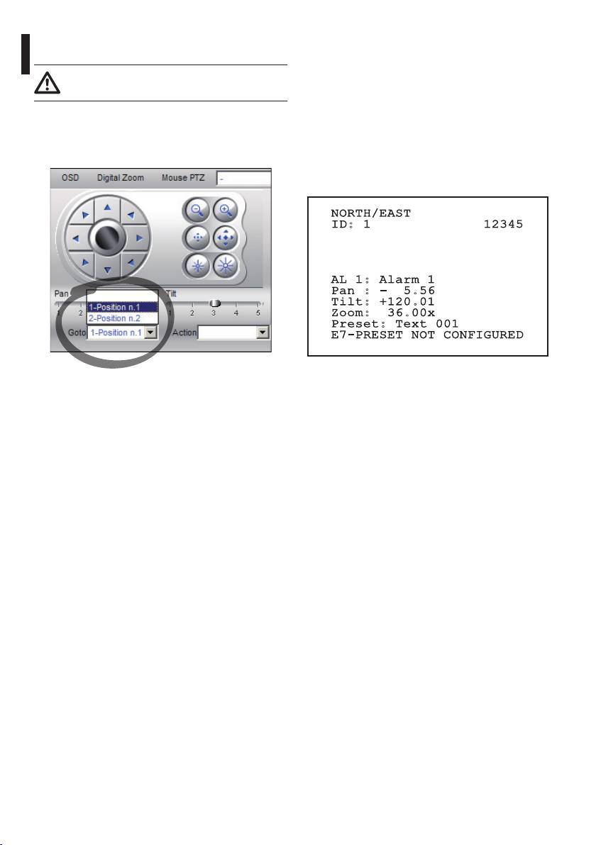
Set the preset positions for the other units in the
10 Instructions for safe
same way.
operation
Close the NVR application and re-start it to
save the settings.
10.1 Visualizing the state of the
When the application is re-started, the preset
pan & tilt
positions can be loaded using the Go To command
on the control panel, and selecting the desired
During normal operation the pan & tilt displays
position.
on screen, at user's choice, the data organized as
illustrated. The visualization can be enabled or
disabled (9.6.5 Display Menu, page48).
NORTH/EAST
EN - English - Instructions manual
ID: 1 12345
AL 1: Alarm 1
Pan : - 5.56
Tilt: +120.01
Zoom: 36.00x
Preset: Text 001
E7-PRESET NOT CONFIGURED
Fig. 133
Fig. 132
NORTH/EAST: Name of the area where one is
To control the other available functions, such as
currently located;
recording on disc, playback and snapshot, and for
ID: 1: Receiver’s address;
other detailed information about using the software,
12345: Complete list of active alarms;
see the manual on the installation CD: NVR User
Manual.
AL 1: Alarm 1: Text regarding the last active alarm;
Pan: - 5.56/Tilt: +120.01/Zoom: 36.00x: Current
position of Pan, Tilt and Zoom;
Preset: Text 001: Name of selected active preset;
E7-PRESET NOT CONFIGURED: The following eld
shows the errors found while the system was running
or the commands received via serial (visualization can
be enabled or disabled only for received commands).
64
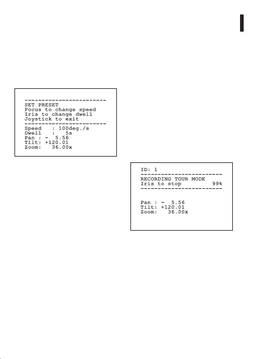
10.2 Saving the current position
10.5 Enabling Autopan Function
(Preset)
Using the control keyboard it is possible to enable the
Instructions manual - English - EN
Autopan (for further information, refer to the manual
10.2.1 Quick save
of the keyboard in use or to Tab. 11, page68).
Using the control keyboard it is possible to save the
Disabling can be carried out by moving the joystick
current position (for further information, refer to the
or by recalling a dierent type of movement.
manual of the keyboard in use).
To congure the Autopan function, refer to 9.6.4.7
During the saving stage, it is possible to change the
Autopan Menu, page47.
speed at which Preset is reached using keys Focus
Far/Focus Near and to change the waiting time using
10.6 Recalling a pattern (Tour)
keys Iris Open/Iris Close.
The Tour functioning mode allows the repetition of a
previously recorded route in a continuous manner.
The pan & tilt can store up to 3 Tours, each lasting no
------------------------
SET PRESET
more than 2 minutes.
Focus to change speed
To save a Tour, enter the special preset of the number
Iris to change dwell
of Tour to be saved using the keyboard (Tab. 11, page
Joystick to exit
------------------------
68).
Speed : 100deg./s
To simplify the recording of the Tour, the pan &
Dwell : 5s
Pan : - 5.56
tilt automatically limits the speed of the Pan & Tilt
Tilt: +120.01
depending on the Zoom factor.
Zoom: 36.00x
While the Tour is being recorded, the remaining
recording time is displayed, as shown in the gure.
Fig. 134
ID: 1
10.2.2 Saving from the Menu
------------------------
RECORDING TOUR MODE
Refer to 9.6.4.3 Preset Menu, page45.
Iris to stop 99%
------------------------
10.3 Recalling a position (Scan)
Using the control keyboard it is possible to recall a
Pan : - 5.56
previously saved position (for further information,
Tilt: +120.01
refer to the manual of the keyboard in use).
Zoom: 36.00x
10.4 Enabling Patrol function
Using the control keyboard it is possible to enable the
automatic patrol (for further information, refer to the
Fig. 135
manual of the keyboard in use or to Tab. 11, page68).
To interrupt recording, press the Iris Open or Iris Close
Disabling can be carried out by moving the joystick
key.
or by recalling a dierent type of movement.
To start the play-back of a Tour, enter the special
To congure the Patrol function, refer to 9.6.4.6 Patrol
preset of the number of Tour to be displayed using
Menu, page47.
the keyboard (Tab. 11, page68).
65

10.7 Recalling the Home position
10.9 Enabling the Washer
Using the control keyboard it is possible to recall
(Washer)
a previously saved Home position (Scan No. 1)
(for further information, refer to the manual of the
Do not use the wiper when the outside
keyboard in use).
temperature is below 0°C or in case of ice.
To enable/disable the Washer refer to the manual of
10.8 Enabling the Wiper (Wiper)
the keyboard or to Tab. 11, page68.
Do not use the wiper when the outside
To congure the Washer, refer to 9.6.7 Washer Menu,
temperature is below 0°C or in case of ice.
page50.
To enable/disable the Wiper refer to the manual of
10.10 Reboot the device
the keyboard or to Tab. 11, page68.
EN - English - Instructions manual
By means of the control keyboard it is possible to
If it is left on, the Wiper automatically
send the device resetting command (for further
disables itself.
information, refer to the manual of the keyboard in
use or to Tab. 11, page68.
66

10.11 Manual correction of a preset focusing
Load the preset whose focus needs to be changed using the Scan command; change the focus using the
Instructions manual - English - EN
appropriate keys Focus Far/Focus Near without changing the Pan/Tilt/Zoom position; then save the preset using
the appropriate Preset command.
The manual correction of the Preset works only if the Daytime/Nigh-time Autofocus elds are
disabled (9.6.4.5 Preset Menu (Preset Utilities), page46).
SPECIAL CONTROLS
Control Protocol
MACRO PELCO D SENSORMATIC ERNITEC PANASONIC
Tour 1 Start
Save Preset 77 Save Preset 77 Save Preset 77 Save Preset 77 Save Preset 77
recording
Save Pattern 2 Start recording
Save Preset 47
pattern 3
Tour 2 Start
Save Preset 78 Save Preset 78 Save Preset 78 Save Preset 78 Save Preset 78
recording
Save Pattern 3
Save Preset 48
Tour 3 Start
Save Preset 79 Save Preset 79 Save Preset 79 Save Preset 79 Save Preset 79
recording
Save Pattern 4
Save Preset 50
Tour 1 Start Save Preset 80 Save Preset 80 Save Preset 80 Save Preset 80 Save Preset 80
Pattern 2 Run pattern 3
Save Preset 51
Tour 2 Start Save Preset 81 Save Preset 81 Save Preset 81 Save Preset 81 Save Preset 81
Pattern 3
Save Preset 52
Tour 3 Start Save Preset 82 Save Preset 82 Save Preset 82 Save Preset 82 Save Preset 82
Pattern 4
Save Preset 53
Tour Record
Iris Open/Close IrisOpen/Close Iris Open/Close Iris Open/Close Iris Open/Close
Stop
Ack Save new pattern
Wiper Start Save Preset 85 Save Preset 85 Save Preset 85 Save Preset 85 Save Preset 85
Aux 3 ON Aux 3 ON Aux 3 ON Aux 3 ON Save Preset 54
Wip+
Wiper Stop Save Preset 86 Save Preset 86 Save Preset 86 Save Preset 86 Save Preset 86
Aux 3 OFF Aux 3 OFF Aux 3 OFF Aux 3 OFF Save Preset 55
Wip-
Washer Save Preset 87 Save Preset 87 Save Preset 87 Save Preset 87 Save Preset 87
Aux 4 ON Aux 4 ON Aux 4 ON Aux 4 ON Save Preset 56
Was+
Night Mode
Save Preset 88 Save Preset 88 Save Preset 88 Save Preset 88 Save Preset 88
on
Save Preset 57
Night Mode
Save Preset 89 Save Preset 89 Save Preset 89 Save Preset 89 Save Preset 89
o
Save Preset 58
67

SPECIAL CONTROLS
Control Protocol
MACRO PELCO D SENSORMATIC ERNITEC PANASONIC
Reboot the
Save Preset 94 Save Preset 94 Save Preset 94 Save Preset 94 Save Preset 94
device
Ini+
Faster+ Zoom out+
Save Preset 61
Focus far+ Iris open
Enabling
Save Preset 95 Save Preset 95 Save Preset 95 Save Preset 95 Save Preset 95
OSM
Men+
Iris open+ Focus+
Save Preset 46
Zoom out
Patrol Start Save Preset 93 Save Preset 93 Save Preset 93 Save Preset 93 Save Preset 93
Pat+ Pattern Run pattern 1 Run patrol Save Preset 60
EN - English - Instructions manual
Patrol Stop Save Preset 92 Save Preset 92 Save Preset 92 Save Preset 92 Save Preset 92
Joystick Joystick Joystick Joystick Joystick
Pat-
Save Preset 59
Autopan
Save Preset 99 Save Preset 99 Save Preset 99 Save Preset 99 Save Preset 99
Start
Apa+ Pattern 1 Run pattern 2 Run autopan Save Preset 63
Autopan
Save Preset 96 Save Preset 96 Save Preset 96 Save Preset 96 Save Preset 96
Stop
Joystick Joystick Joystick Joystick Joystick
Apa-
Save Preset 62
Carry out a
Save Preset 74 Save Preset 74 Save Preset 74 Save Preset 74 Save Preset 74
FFC
Save Preset 43
Video
Save Preset 75 Save Preset 75 Save Preset 75 Save Preset 75 Save Preset 75
2 - thermal
Save Preset 44
camera
Video 2
Save Preset 76 Save Preset 76 Save Preset 76 Save Preset 76 Save Preset 76
integrated
module
Tab. 11
68
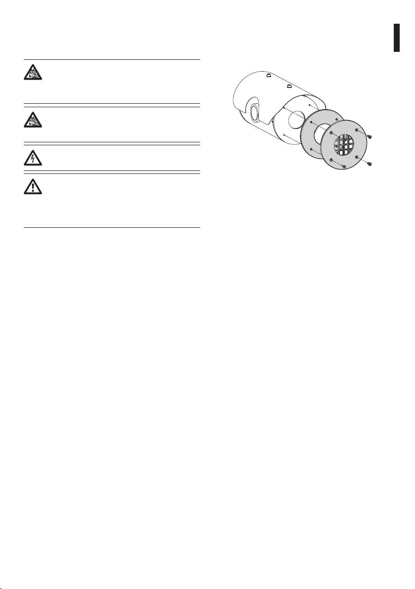
11.2.1.2 Cleaning the germanium window
11 Maintaining and
Remove the protective grid and spacer unscrewing
cleaning
the 4 socket at cap screws on the front of the
Instructions manual - English - EN
enclosure using 2mm no sparking hex wrench.
Before doing any technical work or
maintenance on the device, make sure that
potentially explosive atmosphere is not
present.
To reduce the risk of ignition, don’t open
the device when a potentially explosive
atmosphere is present.
Before doing any technical work on the
device, disconnect the power supply.
Repair of this equipment shall be carried
Fig. 136
out by suitably trained or supervised by
Use neutral soap diluted with water. Take extra care
VIDEOTEC personnel in accordance with
not to scratch or damage the outer surface treated
the applicable code of practice (e.g. IEC/EN
with carbon coating. Damage to this coating could
60079-19).
interfere with the transparency of the surface to
infrared light. Do not use ethyl alcohol, solvents,
11.1 System conguration and
hydrogenated hydrocarbons, strong acids or alkalis.
statistics display
Using these products will irreparably damage the
germanium surface.
When contacting Videotec for assistance please go
Once done cleaning, reassemble the spacer and the
to the conguration and statistic page and send a
grid.
screenshot or serial number and device identication
code.
11.2.1.3 Cleaning the device
This should be done regularly. If a layer of dust
11.2 Maintenance and cleaning
accumulates on the outside of the housing, it should
by users
never be more than 5mm thick. The device should be
cleaned using a damp cloth; compressed air must not
11.2.1 Routine (to be carried out
be used. Maintenance frequency will depend on the
regularly)
type of environment in which the housing is used.
11.2.1.1 Cleaning the glass
11.2.1.4 Inspecting the cables
Water should be used, or a liquid detergent that will
The cables should not show signs of damage or wear,
not generate a hazardous situation.
which could generate hazardous situations. In this
case extraordinary maintenance is necessary.
69
11.2.2 Extraordinary (to be done only
12 Disposal of waste
under particular circumstances)
materials
Any other intervention that is not
comprised in the routine interventions
This symbol mark and recycle system
must be done in absence of potentially
are applied only to EU countries and not
explosive atmosphere.
applied to the countries in the other area of
the world.
For damage to any parts, repair or
Your product is designed and manufactured with
replacement must be done by, or under
high quality materials and components which can be
supervision of VIDEOTEC.
recycled and reused.
Whenever replacing the parts as indicated,
This symbol means that electrical and electronic
EN - English - Instructions manual
always use VIDEOTEC original spare parts
equipment, at their end-of-life, should be disposed of
and meticulously follow the maintenance
separately from your household waste.
instructions supplied with every spare parts
Please dispose of this equipment at your local
kit.
Community waste collection or Recycling centre.
In the European Union there are separate collection
The manufacturer declines all liability for
systems for used electrical and electronic products.
damage to any of the apparatus mentioned
in this handbook, when resulting from
tampering, use of non-original spare parts,
and from installation and maintenance/
repairs performed by non-authorised, non-
skilled personnel.
In all such circumstances, the product
should be sent to the workshop for the
necessary repairs or maintenance.
70
PROBLEM The monitor does not show
13 Troubleshooting
the picture taken but shows
Ask for assistance from skilled personnel if:
an image of the type:
Instructions manual - English - EN
• The unit is damaged after being dropped;
• There is noticeable deterioration in performance
Address : 1
of the unit.
Protocol : MACRO
RS485-1:38400 N81 RX
• The unit does not work properly, even though
RS485-2:38400 N81 REPEAT
all the instructions in this handbook have been
followed.
232 : FW UPGRADE ONLY
FW: 0a (Jun 4 2009)
PROBLEM
The device is o and shows no
HW: 000-0001
signs of life.
DIP1.1: VIEW CONF. ON
CAUSE Wiring error, blown fuse.
SOLUTION Make sure the connections are
correct; check the continuity of the
CAUSE Display Conguration dip-switch
fuses and if one is blown replace it
rocker (DIP1, SW1).
using the size as indicated in the
table. If blown fuses are a frequent
SOLUTION Switch o the pan & tilt, switch
problem, contact your authorised
down the dip-switch (DIP1, SW1).
service centre.
Switch-on the unit again.
PROBLEM
The preset position settings
PROBLEM
During start-up the pan & tilt
do not correspond to the
is disabled and the following
shooting area.
type of message is shown:
CAUSE Loss of absolute position
reference point.
Address : 1
SOLUTION Follow the procedure to calibrate
DE-ICE PROCEDURE
the P&T from the keyboard (see the
IN PROGRESS…
appropriate handbook), or reset the
REMAINING MINUTES:59
apparatus by switching it o and on
again.
CAUSE Environment temperature is very
low.
71

SOLUTION Wait until the end of the pre-heating
PROBLEM Error E3-PATROL WITHOUT
procedure. If the air temperature is
PRESET or error E4-PATROL, 1
too low the unit will remain disabled
PRESET ONLY.
and the following message will be
CAUSE The presets have not been
shown:
programmed.
SOLUTION Program two or more presets and
Address : 1
then update the Patrol conguration
DE-ICE PROCEDURE
menu (10.2 Saving the current
position (Preset), page65 and 9.6.4.6
------------------------
Patrol Menu, page47).
SYSTEM BLOCKED
TEMPERATURE TOO LOW
------------------------
PROBLEM
Error E5-IR TEMP. TOO HIGH or
EN - English - Instructions manual
error E6-IR FAULT.
CAUSE The infrared illuminator is not
working properly.
SOLUTION Seek assistance.
PROBLEM Error E1-AUTOPAN WITHOUT
PROBLEM
Error E7-PRST. NOT
LIMITS.
CONFIGURED.
CAUSE The two presets used as limits
CAUSE Recalling of a non programmed
have not been programmed.
preset.
SOLUTION Program the two presets and then
SOLUTION Save the preset using the relative
update the Autopan conguration
control (10.2 Saving the current
menu (10.2 Saving the current
position (Preset), page65).
position (Preset), page65 and 9.6.4.7
Autopan Menu, page47).
PROBLEM
Error E8-TOUR NOT
CONFIGURED.
PROBLEM
Error E2-WIPER BLOCKED.
CAUSE Recalling of a non congured
CAUSE The wiper is either jammed or
Tour.
broken.
SOLUTION Save the Tour using the relative
SOLUTION Check that the wiper is free to
control (10.6 Recalling a pattern
move; if the problem persists, seek
(Tour), page65).
assistance.
PROBLEM
Error E9-TEMP. TOO LOW.
CAUSE The environment temperature is
too low.
SOLUTION The movements of the P&T unit
is blocked to prevent mechanical
damage.
72

14 Technical data
14.1 MPX
If the equipment is likely to come into contact with
14.1.1 General
Instructions manual - English - EN
aggressive substances, then it is the responsibility of
AISI 316L stainless steel construction
the user to take suitable precautions that prevent it
Passivated and electropolished external surfaces
from being adversely aected, thus ensuring that the
type of protection is not compromised.
RTV silicone rubber
Aggressive substances: Acidic liquids or gases
NBR rotary seals
that may attack metals, or solvents that may aect
Silicone O-ring seals
polymeric materials.
Quick conguration and setup
Suitable precautions: Regular checks as part of
Dynamic positioning control system
routine inspections or establishing from the material’s
data sheet that it is resistant to specic chemicals.
14.1.2 Mechanical
It is the end users responsibility to ensure the
1 3/4" NPT hole for cable glands
materials of construction as detailed are suitable for
Zero backlash
the intended point of installation. If in doubt consult
Horizontal rotation: 360° continous
the manufacturer.
Vertical rotation: -90° to +90°
Variable pan speed: from 0.1° to 100°/s
Variable tilt speed: from 0.1° to 100°/s
Preset accuracy: 0.02°
12mm thick tempered glass window
Integrated Wiper
14.1.3 Electrical/Video
Input voltage:
- 230Vac, 50/60Hz, 120W max
- 24Vac, 50/60Hz, 120W max
- 120Vac, 50/60Hz, 120W max
1 video output 75 Ohm 1Vpp (PAL/NTSC)
Functions: Autopan, Preset, Patrol, Tour (maximum 3),
Autoip
Maximum number of presets:
- VIDEOTEC MACRO Protocol: 250
- ERNITEC protocol: 250
- PANASONIC protocol: 250
- PELCO D Protocol: 99
- AMERICAN DYNAMICS protocol: 95
16-character string for zone and preset titling
I/O alarm card:
- 5 alarm inputs
- 2 relay outputs (1A 30Vac/60Vdc max)
73

IECEx (IEC 60079-0: 2007, IEC 60079-1: 2007, IEC
14.2 Communications
60079-31: 2008)
Conguration through OSD
- Ex d IIC T6 T
a
-40°C to +60°C Gb
2 half-duplex serial RS485 interfaces or full-duplex
- Ex tb IIIC T85°C T
a
-40°C to +60°C Db
RS422
- IP66
Firmware updating from console in remote mode
(only VIDEOTEC MACRO and PELCO D protocols)
14.2.7 Brackets and adapters
Up to 999 units, addressable by means of dip-
MPXWBA AISI 316L stainless steel wall
switches
bracket
Integrated ber optic video/data transceiver
MPXCW AISI 316L stainless steel corner
(optional):
adapter module
- 10bit PCM
MPXCOL AISI 316L stainless steel pole
EN - English - Instructions manual
adapter module
- Half-duplex RS485
MPXWBTA AISI 316L stainless steel
- Multi Mode/Single Mode
parapet or ceiling mounting
IP Streaming Module (optional)
bracket
- MPEG4 compression
14.2.8 Accessories
- Compatible with ONVIF 1.01
OCTEX3/4C Cable gland with gasket EX
- Compatible with VMS Milestone XProtect suite
3/4" NPT, unarmoured cable
- LAN 10/100 Mbit/s RJ45 interface
IECEX-ATEX-GOST
- Resolutions: Full D1 (720x576) @30fps, VGA
OCTEXA3/4C Cable gland with gasket EX
(640x480), CIF (352x288), QCIF (176x144)
3/4" NPT, armoured cable
IECEX-ATEX-GOST
14.2.4 Protocols
OCTEXB3/4C Barrier cable gland 3/4" NPT,
AMERICAN DYNAMICS, ERNITEC, PANASONIC, PELCO
unarmoured cable IECEX-ATEX-
D, VIDEOTEC MACRO*
GOST
The product may be interfaced with devices not manufactured by
VIDEOTEC. It is possible that the interface protocols have changed or
OCTEXBA3/4C Barrier cable gland 3/4" NPT,
are in a dierent conguration from earlier tested units by VIDEOTEC.
armoured cable IECEX-ATEX-
VIDEOTEC recommends a test prior to installation. VIDEOTEC will
GOST
not be liable for any installation costs or lost revenues in the event a
OCTEX3/4 Cable gland with gasket EX
compatibility problem will occur.
3/4" NPT, unarmoured cable
*AMERICAN DYNAMICS, ERNITEC, PANASONIC, PELCO are registered
ATEX
trademarks.
OCTEXA3/4 Cable gland with gasket EX
14.2.5 Environment
3/4" NPT, armoured cable ATEX
Indoor / Outdoor
14.2.9 Package
Operating temperature: -40°C / +60°C (-40°F / +140°F)
Unit weight:
Installation temperature (not operative): -40°C /
MPX 27kg (60lb)
+60°C (-40°F / +140°F)
Surge immunity: up to 2KV line to line, up to 4KV line
to earth (Class 4)
14.2.6 Certications
ATEX (EN 60079-0: 2009, EN 60079-1: 2007, EN 60079-
31: 2009)
-
b
II 2 G Ex d IIC T6 T
a
-40°C to +60°C Gb
-
b
II 2 D Ex tb IIIC T85°C T
a
-40°C to +60°C Db
- IP66
74

14.3 MPXT
14.3.1 General
Instructions manual - English - EN
AISI 316L stainless steel construction
Passivated and electropolished external surfaces
RTV silicone rubber
NBR rotary seals
Silicone O-ring seals
Quick conguration and setup
Dynamic positioning control system
14.3.2 Mechanical
1 3/4" NPT hole for cable glands
Zero backlash
Horizontal rotation: 360° continous
Vertical rotation: -90° to +90°
Variable pan speed: from 0.1° to 100°/s
Variable tilt speed: from 0.1° to 100°/s
Preset accuracy: 0.02°
12mm thick tempered glass window
8mm thick germanium window
Integrated Wiper
14.3.3 Electrical/Video
Input voltage:
- 230Vac, 50/60Hz, 120W max
- 24Vac, 50/60Hz, 120W max
- 120Vac, 50/60Hz, 120W max
2 video outputs 75 Ohm 1Vpp (PAL/NTSC)
Functions: Autopan, Preset, Patrol, Tour (maximum 3),
Autoip
Maximum number of presets:
- VIDEOTEC MACRO Protocol: 250
- ERNITEC protocol: 250
- PANASONIC protocol: 250
- PELCO D Protocol: 99
- AMERICAN DYNAMICS protocol: 95
16-character string for zone and preset titling
I/O alarm card:
- 5 alarm inputs
- 2 relay outputs (1A 30Vac/60Vdc max)
75

IECEx (IEC 60079-0: 2007, IEC 60079-1: 2007, IEC
14.4 Communications
60079-31: 2008)
Conguration through OSD
- Ex d IIC T6 T
a
-40°C to +60°C Gb
2 half-duplex serial RS485 interfaces or full-duplex
- Ex tb IIIC T85°C T
a
-40°C to +60°C Db
RS422
- IP66
Firmware updating from console in remote mode
(only VIDEOTEC MACRO and PELCO D protocols)
14.4.7 Brackets and adapters
Up to 999 units, addressable by means of dip-
MPXWBA AISI 316L stainless steel wall
switches
bracket
Integrated ber optic video/data transceiver
MPXCW AISI 316L stainless steel corner
(optional):
adapter module
- 10bit PCM
MPXCOL AISI 316L stainless steel pole
EN - English - Instructions manual
adapter module
- Half-duplex RS485
MPXWBTA AISI 316L stainless steel
- Multi Mode/Single Mode
parapet or ceiling mounting
IP Streaming Module (optional)
bracket
- MPEG4 compression
14.4.8 Accessories
- Compatible with ONVIF 1.01
OCTEX3/4C Cable gland with gasket EX
- Compatible with VMS Milestone XProtect suite
3/4" NPT, unarmoured cable
- LAN 10/100 Mbit/s RJ45 interface
IECEX-ATEX-GOST
- Resolutions: Full D1 (720x576) @30fps, VGA
OCTEXA3/4C Cable gland with gasket EX
(640x480), CIF (352x288), QCIF (176x144)
3/4" NPT, armoured cable
IECEX-ATEX-GOST
14.4.4 Protocols
OCTEXB3/4C Barrier cable gland 3/4" NPT,
AMERICAN DYNAMICS, ERNITEC, PANASONIC, PELCO
unarmoured cable IECEX-ATEX-
D, VIDEOTEC MACRO*
GOST
The product may be interfaced with devices not manufactured by
VIDEOTEC. It is possible that the interface protocols have changed or
OCTEXBA3/4C Barrier cable gland 3/4" NPT,
are in a dierent conguration from earlier tested units by VIDEOTEC.
armoured cable IECEX-ATEX-
VIDEOTEC recommends a test prior to installation. VIDEOTEC will
GOST
not be liable for any installation costs or lost revenues in the event a
OCTEX3/4 Cable gland with gasket EX
compatibility problem will occur.
3/4" NPT, unarmoured cable
*AMERICAN DYNAMICS, ERNITEC, PANASONIC, PELCO are registered
ATEX
trademarks.
OCTEXA3/4 Cable gland with gasket EX
14.4.5 Environment
3/4" NPT, armoured cable ATEX
Indoor / Outdoor
14.4.9 Package
Operating temperature: -40°C / +60°C (-40°F / +140°F)
Unit weight:
Installation temperature (not operative): -40°C /
MPXT 31kg (68lb)
+60°C (-40°F / +140°F)
Surge immunity: up to 2KV line to line, up to 4KV line
to earth (Class 4)
14.4.6 Certications
ATEX (EN 60079-0: 2009, EN 60079-1: 2007, EN 60079-
31: 2009)
-
b
II 2 G Ex d IIC T6 T
a
-40°C to +60°C Gb
-
b
II 2 D Ex tb IIIC T85°C T
a
-40°C to +60°C Db
- IP66
76

14.5 Electrical rating
ELECTRICAL RATING
Instructions manual - English - EN
Power Supply Normal usage to be specied on product label Short term de-icing cicle. Peak maintaining a mini-
mum internal temp at 5°C
230Vac 0.11A, 50/60Hz, 25.3W 0.52A, 50/60Hz, 120W
24Vac 1.08A, 50/60Hz, 25.9W 5A, 50/60Hz, 120W
120Vac 0.21A, 50/60Hz, 25.2W 1A, 50/60Hz, 120W
Tab. 12
14.6 Cable glands
SELECTION TABLE FOR CABLE GLANDS
Zone, Gas Cable gland
Certication Operating
Cable Cable glands
Diameter of
Under armor
type
temperature
part code
the external
cable diame-
cable (mm)
ter (mm)
IIC, Zone 1 or
Barrier IECEX/ATEX/
-60 / +80°C
Not armored OCTEXB3/4C 13 - 20.2
Zone 2
GOST
(-76°F /
Armored OCTEXBA3/4C 16.9 - 26
IIB or IIA,
+176°F)
Zone 1
IIB or IIA,
With gasket IECEX/ATEX/
-60 / +100°C
Not armored OCTEX3/4C 13 - 20.2
Zone 2
GOST
(-76°F /
Armored OCTEXA3/4C 16.9 - 26 11.1 - 19.7
+212°F)
ATEX -20 / +80°C
Not armored OCTEX3/4 14 - 17
(-4°F / + 176°F)
Armored OCTEXA3/4 18 - 23 14 - 17
Tab. 13
77

14.7 Camera
ANALOGUE CAMERAS AVAILABLE
SONY Day/Night 36x SONY Day/Night 28x High
sensitivity
PAL NTSC PAL NTSC
Optical zoom 36x 28x
Wide Dynamic Range (Fix/Auto) •
True progressive SCAN •
Digital image stabilisation • •
White balance Auto, ATW, Indoor, Outdoor (Fix/
Auto, ATW, Indoor, Outdoor (Fix/
Auto), Sodium Vapor Lamp (Fix/
Auto), Sodium Vapor Lamp (Fix/
Auto)
Auto)
EN - English - Instructions manual
High horizontal resolution Up to 550 TV Lines Up to 550 TV Lines
Day/Night (Auto ICR) • •
Image Sensor 1/4" EXView HAD CCD 1/4" Super HAD CCD II
Number of eective Pixels ~ 440 000 pixel ~ 380 000 pixel ~ 440 000 pixel ~ 380 000 pixel
Min. night Illumination (ICR ON) (typical) 0.01 Lux / 1/3s 0.01 Lux / 1/4s 0.0015 Lux / 1/3s 0.0015 Lux / 1/4s
Min. day Illumination (ICR OFF) (typical) 0.1 Lux / 1/3s 0.1 Lux / 1/4s 0.16 Lux / 1/3s 0.16 Lux / 1/4s
“Shutter Time” automatic increase to improve the night
• •
surveillance
S/N ratio Greater than 50dB Greater than 50dB
AE control Automatic, Shutter priority,
Automatic, Shutter priority,
Diaphragm priority, Brightness
Diaphragm priority, Brightness
priority and Manual
priority and Manual
Back light compensation On/O On/O
Spherical masking (3D) of Privacy zones with automatic
• •
upgrade
Privacy Zone Masking On/O (24 positions) On/O (24 positions)
Maximum number of masking blocks to be displayed 8 8
Resolution of masking blocks 160x120 HxV 160x120 HxV
Masking Up to 15 dierent masking types: 14
Up to 15 dierent masking types: 14
colour types or mosaic
colour types or mosaic
Focusing system Auto (Sensitivity: Normal, Low),
Auto (Sensitivity: Normal, Low),
Trigger PTZ, Manual
Trigger PTZ, Manual
“Smart” lens control SONY Modular Automatic Lens
SONY Modular Automatic Lens
Reset Technology
Reset Technology
High Zoom and Wide Horizontal Field of View Capa-
• •
bility
Optical zoom 36x, f=3.4 (wide) to 122.4mm (tele)
28x, f=3.5 (wide) to 98mm (tele) /
/ F1.6 to F4.5
F1.35 to F3.7
Digital Zoom 12x (432x with optical zoom) 12x (336x with optical zoom)
Angle of view (A) 57.8 degrees (wide) to 1.7 degrees
55.8 degrees (wide) to 2.1 degrees
(tele)
(tele)
Minimum object distance 320mm (12.6in) (wide) to 1500mm
10mm (0.4in) (wide) to 1500mm
(59.1in) (tele)
(59.1in) (tele)
Electronic Iris Speed 1/1 ÷ 1/10 000s 1/1 ÷ 1/10 000s
Tab. 14
78

THERMAL CAMERAS AVAILABLE RESOLUTION 160X120
Lens 19mm Lens 13mm Lens 9mm
PAL NTSC PAL NTSC PAL NTSC
Image sensor Uncooled VOx microbolometer Uncooled VOx microbolometer Uncooled VOx microbolometer
Resolution 160x120 160x120 160x120 160x120 160x120 160x120
Pixel dimensions 25m 25m 25m
Spectral response - long wave infrared (LWIR) from 7.5m to 13.5m from 7.5m to 13.5m from 7.5m to 13.5m
Internal shutter (only for sensor compensation) Video stop < 1sec. Video stop < 1sec. Video stop < 1sec.
Digital Detail Enhancement (DDE) • • •
Digital Zoom 2x, 4x 2x, 4x 2x, 4x
Image updating frequency 8.3fps, 25fps 7.5fps, 30fps 8.3fps, 25fps 7.5fps, 30fps 8.3fps, 25fps 7.5fps, 30fps
Scene temperature range -40°C ÷ +160°C (-40°F ÷ +320°F) -40°C ÷ +160°C (-40°F ÷ +320°F) -40°C ÷ +160°C (-40°F ÷ +320°F)
Horizontal eld of view 12° 17° 25°
Vertical eld of view 10° 14° 20°
F-number F/1.25 F/1.25 F/1.25
Thermal sensitivity (NEdT) < 50mK a f/1.0 < 50mK a f/1.0 < 50mK a f/1.0
Person (detection / recognition / identication) 450m / 112m / 56m (1476ft / 367ft /
300m / 74m / 37m (984ft / 243ft / 121ft) 205m / 52m / 26m (673ft / 171ft / 85ft)
184ft)
Auto (detection / recognition / identication) 1280m / 330m / 165m (4199ft / 1083ft
840m / 215m / 108m (2756ft / 705ft /
590m / 150m / 74m (1936ft / 492ft /
/ 541ft)
354ft)
243ft)
Tab. 15
79
Instructions manual - English - EN

EN - English - Instructions manual
80
THERMAL CAMERAS AVAILABLE RESOLUTION 320X256
Lens 35mm Lens 25mm Lens 19mm Lens 13mm Lens 9mm
PAL NTSC PAL NTSC PAL NTSC PAL NTSC PAL NTSC
Image sensor Uncooled VOx microbo-
Uncooled VOx microbo-
Uncooled VOx microbo-
Uncooled VOx microbo-
Uncooled VOx microbo-
lometer
lometer
lometer
lometer
lometer
Resolution 320x256 320x240 320x256 320x240 320x256 320x240 320x256 320x240 320x256 320x240
Pixel dimensions 25m 25m 25m 25m 25m
Spectral response - long wave infrared
from 7.5m to 13.5m from 7.5m to 13.5m from 7.5m to 13.5m from 7.5m to 13.5m from 7.5m to 13.5m
(LWIR)
Internal shutter (only for sensor compen-
Video stop < 1sec. Video stop < 1sec. Video stop < 1sec. Video stop < 1sec. Video stop < 1sec.
sation)
Digital Detail Enhancement (DDE) • • • • •
Digital Zoom 2x, 4x 2x, 4x 2x, 4x 2x, 4x 2x, 4x
Image updating frequency 8.3fps, 25fps 7.5fps, 30fps 8.3fps, 25fps 7.5fps, 30fps 8.3fps, 25fps 7.5fps, 30fps 8.3fps, 25fps 7.5fps, 30fps 8.3fps, 25fps 7.5fps, 30fps
Scene temperature range -40°C ÷ +160°C (-40°F ÷
-40°C ÷ +160°C (-40°F ÷
-40°C ÷ +160°C (-40°F ÷
-40°C ÷ +160°C (-40°F ÷
-40°C ÷ +160°C (-40°F ÷
+320°F)
+320°F)
+320°F)
+320°F)
+320°F)
Horizontal eld of view 13° 18° 24° 34° 48°
Vertical eld of view 10° 14° 18° 26° 37°
F-number F/1.2 F/1.1 F/1.25 F/1.25 F/1.25
Thermal sensitivity (NEdT) < 50mK a f/1.0 < 50mK a f/1.0 < 50mK a f/1.0 < 50mK a f/1.0 < 50mK a f/1.0
Person (detection / recognition / identi-
780m / 190m / 97m (2.559ft
560m / 140m / 70m (1.837ft
450m / 112m / 56m (1476ft
300m / 74m / 37m (984ft /
205m / 56m / 26m (673ft /
cation)
/ 623ft / 318ft)
/ 459ft / 230ft)
/ 367ft / 184ft)
243ft / 121ft)
184ft / 85ft)
Auto (detection / recognition / identi-
2150m / 560m / 280m
1550m / 400m / 200m
1280m / 330m / 165m
840m / 215m / 108m
590m / 150m / 74m (1936ft
cation)
(7054ft / 1837ft / 919ft)
(5085ft / 1312ft / 656ft)
(4199ft / 1083ft / 541ft)
(2756ft / 705ft / 354ft)
/ 492ft / 243ft)
Tab. 16

THERMAL CAMERAS AVAILABLE RESOLUTION 336X256
Lens 35mm Lens 25mm Lens 19mm Lens 13mm Lens 9mm
PAL NTSC PAL NTSC PAL NTSC PAL NTSC PAL NTSC
Image sensor Uncooled VOx microbo-
Uncooled VOx microbo-
Uncooled VOx microbo-
Uncooled VOx microbo-
Uncooled VOx microbo-
lometer
lometer
lometer
lometer
lometer
Resolution 320x256 320x240 320x256 320x240 320x256 320x240 320x256 320x240 320x256 320x240
Pixel dimensions 17m 17m 17m 17m 17m
Spectral response - long wave infrared
from 7.5m to 13.5m from 7.5m to 13.5m from 7.5m to 13.5m from 7.5m to 13.5m from 7.5m to 13.5m
(LWIR)
Internal shutter (only for sensor compen-
Video stop < 1sec. Video stop < 1sec. Video stop < 1sec. Video stop < 1sec. Video stop < 1sec.
sation)
Digital Detail Enhancement (DDE) • • • • •
Digital Zoom 2x, 4x 2x, 4x 2x, 4x 2x, 4x 2x, 4x
Image updating frequency 8.3fps, 25fps 7.5fps, 30fps 8.3fps, 25fps 7.5fps, 30fps 8.3fps, 25fps 7.5fps, 30fps 8.3fps, 25fps 7.5fps, 30fps 8.3fps, 25fps 7.5fps, 30fps
Scene temperature range -40°C ÷ +160°C (-40°F ÷
-40°C ÷ +160°C (-40°F ÷
-40°C ÷ +160°C (-40°F ÷
-40°C ÷ +160°C (-40°F ÷
-40°C ÷ +160°C (-40°F ÷
+320°F)
+320°F)
+320°F)
+320°F)
+320°F)
Horizontal eld of view 9,3° 13° 17° 25° 35°
Vertical eld of view 7,1° 10° 13° 19° 27°
F-number F/1.2 F/1.1 F/1.25 F/1.25 F/1.25
Thermal sensitivity (NEdT) < 50mK a f/1.0 < 50mK a f/1.0 < 50mK a f/1.0 < 50mK a f/1.0 < 50mK a f/1.0
Person (detection / recognition / identi-
1140m / 280m / 142m
820m / 210m / 104m
570m / 144m / 72m (1870ft
390m / 95m / 47m (1280ft /
250m / 63m / 31m (820ft /
cation)
(3740ft / 919ft / 466ft)
(2690ft / 689ft / 341ft)
/ 472ft / 236ft)
312ft / 154ft)
207ft / 102ft)
Auto (detection / recognition / identi-
3000m / 800m / 200m
2200m / 580m / 290m
1550m / 400m / 200m
1080m / 275m / 140m
720m / 175m / 88m (2362ft
cation)
(9843ft / 2625ft / 656ft)
(7218ft / 1903ft / 951ft)
(5085ft / 1312ft / 656ft)
(3543ft / 902ft / 459ft)
/ 574ft / 289ft)
Tab. 17
81
Instructions manual - English - EN

EN - English - Instructions manual
82
THERMAL CAMERAS AVAILABLE RESOLUTION 640X512
Lens 35mm Lens 25mm Lens 19mm Lens 13mm Lens 9mm
PAL NTSC PAL NTSC PAL NTSC PAL NTSC PAL NTSC
Image sensor Uncooled VOx microbo-
Uncooled VOx microbo-
Uncooled VOx microbo-
Uncooled VOx microbo-
Uncooled VOx microbo-
lometer
lometer
lometer
lometer
lometer
Resolution 640x512 640x480 640x512 640x480 640x512 640x480 640x512 640x480 640x512 640x480
Pixel dimensions 17m 17m 17m 17m 17m
Spectral response - long wave infrared
from 7.5m to 13.5m from 7.5m to 13.5m from 7.5m to 13.5m from 7.5m to 13.5m from 7.5m to 13.5m
(LWIR)
Internal shutter (only for sensor compen-
Video stop < 1sec. Video stop < 1sec. Video stop < 1sec. Video stop < 1sec. Video stop < 1sec.
sation)
Digital Detail Enhancement (DDE) • • • • •
Digital Zoom 2x, 4x 2x, 4x 2x, 4x 2x, 4x 2x, 4x
Image updating frequency 8.3fps, 25fps 7.5fps, 30fps 8.3fps, 25fps 7.5fps, 30fps 8.3fps, 25fps 7.5fps, 30fps 8.3fps, 25fps 7.5fps, 30fps 8.3fps, 25fps 7.5fps, 30fps
Scene temperature range -40°C ÷ +160°C (-40°F ÷
-40°C ÷ +160°C (-40°F ÷
-40°C ÷ +160°C (-40°F ÷
-40°C ÷ +160°C (-40°F ÷
-40°C ÷ +160°C (-40°F ÷
+320°F)
+320°F)
+320°F)
+320°F)
+320°F)
Horizontal eld of view 18° 25° 32° 45° 69°
Vertical eld of view 14° 20° 26° 37° 56°
F-number F/1.2 F/1.1 F/1.25 F/1.25 F/1.4
Thermal sensitivity (NEdT) < 50mK a f/1.0 < 50mK a f/1.0 < 50mK a f/1.0 < 50mK a f/1.0 < 50mK a f/1.0
Person (detection / recognition / identi-
1140m / 280m / 142m
820m / 210m / 104m
570m / 144m / 72m (1870ft
390m / 95m / 47m (1280ft /
300m / 81m / 38m (984ft /
cation)
(3740ft / 919ft / 466ft)
(2690ft / 689ft / 341ft)
/ 472ft / 236ft)
312ft / 154ft)
266ft / 125ft)
Auto (detection / recognition / identi-
3000m / 800m / 400m
2200m / 580m / 290m
1550m / 400m / 200m
1080m / 275m / 140m
820m / 210m / 100m
cation)
(9843ft / 2625ft / 1312ft)
(7218ft / 1903ft / 951ft)
(5085ft / 1312ft / 656ft)
(3543ft / 902ft / 459ft)
(2690ft / 689ft / 328ft)
Tab. 18
15 Technical drawings
The dimensions are in millimetres.
Instructions manual - English - EN
Ø 138Ø 138
N°4 M10N°4 M10
336336
232232
398398
Fig. 137 MAXIMUS MPX.
83
Ø 138Ø 138
N°4 M10N°4 M10
453453
232232
EN - English - Instructions manual
398398
Fig. 138 MAXIMUS MPXT.
84
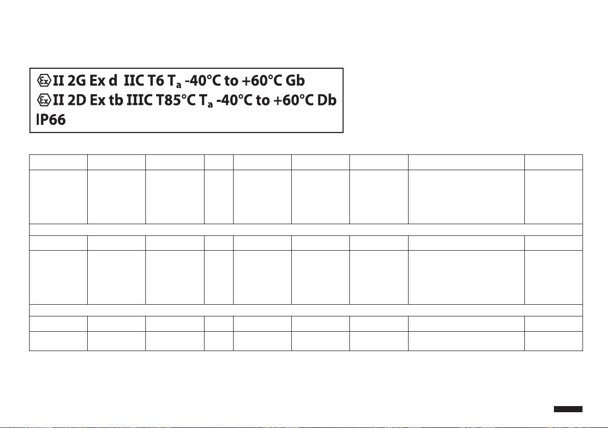
A Appendix - Marking codes
A.1 ATEX Marking
Fig. 139
Ï ÐÐ 2 G Ex d ÐÐC T6 Tfi -40°C to +60°C Gb
Group (surface
Category (high
Gas Explosion-proof
Gas group Gas temperature
Installation temperature range Protection level
device, no mining)
protection degree,
housing for po-
classication
of the equipment
the device in this
tentially explosive
for gas
category can be
environments
installed in zones
1 and 2)
Ï ÐÐ 2 D Ex tb ÐÐÐC T85°C Tfi -40°C to +60°C Db
Group (surface
Category (high
Dusts Dust ignition pro-
Dust group Maximum surface
Installation temperature range Protection level
device, no mining)
protection degree,
tection for zone
temperature for
of the equipment
the device in this
types 21-22
dusts
for dust
category can be
installed in zones
21 and 22)
IP66
IP protection
degree
Tab. 19
85
Instructions manual - English - EN
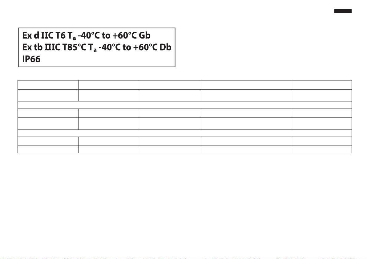
EN - English - Instructions manual
86
A.2 IECEx Mark
Fig. 140
Ex d ÐÐC T6 Tfi -40°C to +60°C Gb
Explosion-proof housing for po-
Gas group Gas temperature classication Installation temperature range Protection level of the equipment
tentially explosive environments
for gas
Ex tb ÐÐÐC T85°C Tfi -40°C to +60°C Db
Dust ignition protection for zone
Dust group Maximum surface temperature
Installation temperature range Protection level of the equipment
types 21-22
for dusts
for dust
IP66
IP protection degree
Tab. 20

A.3 Gas group classication
The table below shows the classication of some gases and vapours, according to the explosion-proof
Instructions manual - English - EN
protection group and the temperature class. For a complete list see IEC/EN 60079-12 and IEC/EN 60079-20.
GAS GROUP CLASSIFICATION
Temperature class (Maximum surface temperature of the housing)
Class T1
T2
T3
T4
T5
T6
450°C (842°F)
300°C (572°F)
200°C (392°F)
135°C (270°F)
100°C
85°C (185°F)
I Methane
IIA Acetone
N-Butane
Petrol
Acetaldehyde
Ethyl nitrate
Ethanol
N-Butyl
Diesel fuel
Ether
Ethyl acetate
Avgas
Ammonia
Heating oil
Pure benzene
N-Hexane
Acetic acid
Carbon monoxide
Methanol
Propane
Toluene
IIB
Ethylene
IIC Hydrogen Acetylene
Carbon disulphide
Tab. 21 The above temperature classes automatically cover the lower classes (T6 is better than T1). Class IIB also covers class IIA. Class
IIC also covers classes IIB and IIA.
TEMPERATURE CLASS T1 T2 T3 T4 T5 T6
Maximum allowed surface temperature (°C) for the housing in the
450 300 200 135 100 85
corresponding class
Tab. 22 Normally referred to the maximum ambient temperature of installation. The lowest ignition temperature of the explosive
atmospheres must be higher than the maximum surface temperature of the housings.
The maximum surface temperature is determined for a 5mm-thick layer of powder and the installation
regulations require a margin of 75K between the surface temperature and the ignition temperature of the
powder under consideration.
87

B Appendix - Flamepath
The maximum constructional gap (ic) is less than that required by Table 2 of EN 60079-1:2007 as detailed below:
MAXIMUM GAP
MINIMUM WIDTH
FLAMEPATH
COMMENT
MM
MM
1. Between component drawings
0.249 25.4 Cylindrical joint sup-
BRT2MPXALBPAN and BRT2MPXTAPINF
ported by bearings
2. Between component drawings
0.245 26.8 Cylindrical joint sup-
BRT2MPXALBTP and BRT2MPXBUT
ported by bearings
3. Between component drawings
0.245 26.8 Cylindrical joint sup-
BRT2MPXALBTS and BRT2MPXBUT
ported by bearings
4. Between component drawings
0.249 25.3 Cylindrical joint sup-
BRT2MPXALWIP and BRT2MPXBUST
ported by bearings
EN - English - Instructions manual
Tab. 23
88


Headquarters Italy Videotec S.p.A.
UK Representative oce
Via Friuli, 6 - I-36015 - Schio (VI) Italy
Tel./Fax +44 01353 775438 (Sales)
Tel. +39 0445 697411 - Fax +39 0445 697414
Tel. +44 0113 815 0047 (Technical support)
Email: info@videotec.com
Tel. +44 0113 815 0031 (Orders/Shipping dept.)
Email: uksales@videotec.com
France Videotec France S.à.r.l.
Asia Pacic Videotec (HK) Ltd
Voie du Futur, Zac des Portes - 27100 - Val-de-Reuil, France
Unit C 24 Floor - Gold King Industrial Building
Tel. +33 2 32094900 - Fax +33 2 32094901
35-41, Tai Lin Pai Road - Kwai Chung, NT, Hong Kong
Email: info@videotec-france.com
Tel. +852 2333 0601 - Fax +852 2311 0026
Email: info@videotec.com.hk
Americas Videotec Security, Inc.
35 Gateway Drive, Suite 100 - Plattsburgh, NY 12901 - U.S.A.
Tel. +1 518 8250020 - Fax +1 425 648 4289
Email: usasales@videotec.com - www.videotec.us
www.videotec.com
MNVCMPXT_1225_EN
