Videotec EXH: инструкция
Раздел: Видеотехника
Тип:
Инструкция к Videotec EXH
EXH
Explosion-proof housing
EN
English - Instructions manual
IT
Italiano - Manuale di istruzioni
FR
Français - Manuel d'instructions
DE
Deutsch - Bedienungslanleitung
RU
Русский - Учебник инструкции


EXH
Explosion-proof housing
EN
English - Instructions manual
ENGLISH

Serial number
Write down the serial number of the product and of any spare part used.
The serial number is given on the label located outside the product packaging and on the metal
j
mark plate.
Code Serial Number

Contents
ENGLISH
EN - English - Instructions manual
1 About this manual ........................................................................................................ 5
1.1 Typographical conventions ................................................................................................................................ 5
2 Notes on copyright and information on trademarks ................................................ 5
3 Safety rules ................................................................................................................... 5
4 Identification ................................................................................................................ 7
4.1 Product description and type designation ................................................................................................... 7
4.1.1 Version for thermal imaging cameras ............................................................................................................................. 7
4.1.2 Version with glass protection device .............................................................................................................................. 7
4.2 Product markings ................................................................................................................................................... 8
5 Preparing the product for use ..................................................................................... 9
5.1 Safety precautions before use ........................................................................................................................... 9
5.2 Contents and unpacking ..................................................................................................................................... 9
6 Installing and assembling ............................................................................................ 9
6.1 Assembly ................................................................................................................................................................... 9
6.1.1 Range of use............................................................................................................................................................................. 9
6.1.2 Specification of maximum values when installing cameras, including lens .................................................... 9
6.2 Installation ..............................................................................................................................................................10
6.2.1 Installing the camera ..........................................................................................................................................................10
6.2.2 Changing the back cover gasket ....................................................................................................................................10
6.3 Operational test ....................................................................................................................................................10
7 Instructions for safe operation ..................................................................................11
7.1 Safe operation .......................................................................................................................................................11
7.1.1 Commissioning .....................................................................................................................................................................11
7.1.2 Safety rules .............................................................................................................................................................................11
7.1.3 Explosion prevention rules ...............................................................................................................................................11
8 Maintaining and cleaning .......................................................................................... 11
8.1 Maintenance and cleaning by users .............................................................................................................. 11
8.1.1 Routine (to be carried out regularly) .............................................................................................................................11
8.1.2 Extraordinary (to be done only under particular circumstances) .......................................................................12
8.2 Spare parts .............................................................................................................................................................. 12
8.3 Repairs ...................................................................................................................................................................... 12
9 Disposal of waste materials .......................................................................................12
10 Technical data ........................................................................................................... 13
10.1 General ..................................................................................................................................................................13
10.2 Mechanical ...........................................................................................................................................................13
10.3 Electrical ................................................................................................................................................................ 13
10.4 Accessories ...........................................................................................................................................................13
10.5 Related products ................................................................................................................................................ 13
10.6 Environment ........................................................................................................................................................13
10.7 Compliance to ..................................................................................................................................................... 14
10.8 Spare parts list .....................................................................................................................................................14
3

10.9 Package .................................................................................................................................................................14
10.10 Cable glands ......................................................................................................................................................14
11 Technical drawings ...................................................................................................15
12 Appendix A - Marking codes ................................................................................... 17
12.1 ATEX Mark .............................................................................................................................................................17
12.2 IECEx Mark ............................................................................................................................................................ 17
12.3 GOST-R Mark ........................................................................................................................................................ 18
12.4 Gas group classification ................................................................................................................................... 18
13 Appendix B - Electrical diagram .............................................................................. 19
14 Appendix C - EXH Declaration ................................................................................. 20
EN - English - Instructions manual
4
1 About this manual
3 Safety rules
Before installing and using this unit, please read this
The manufacturer declines all responsibility
EN - English - Instructions manual
manual carefully. Be sure to keep it handy for later
h
for any damage caused by an improper use
reference.
of the appliances mentioned in this manual.
Furthermore, the manufacturer reserves
1.1 Typographical conventions
the right to modify its contents without any
prior notice. The documentation contained
DANGER!
in this manual has been collected with great
g
High level hazard.
care, the manufacturer, however, cannot
Risk of electric shock; disconnect the
take any liability for its use. The same thing
power supply before proceeding with any
can be said for any person or company
operation, unless indicated otherwise.
involved in the creation and production of
this manual.
DANGER!
o
Explosion hazard.
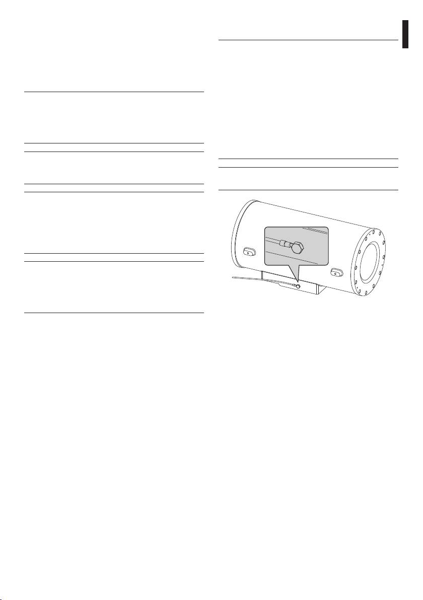
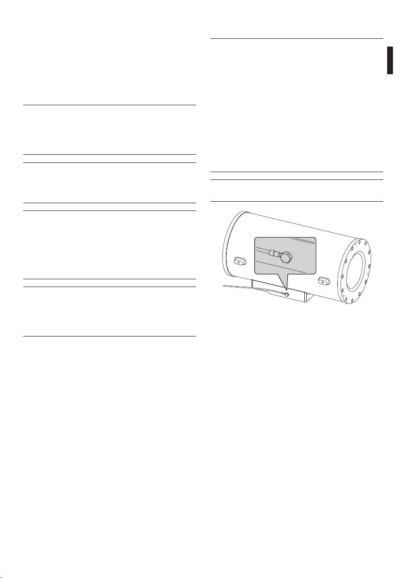
This device must be connected to an earth
Read carefully to avoid danger of explosion.
h
conductor.
WARNING!
h
Medium level hazard.
This operation is very important for the
system to function properly. Please read
the procedure described very carefully and
carry it out as instructed.
INFO
j
Description of system specifications.
We recommend reading this part carefully
in order to understand the subsequent
stages.
Fig. 01 Earth connection.
• Make sure that all the devices are suitable for the
2 Notes on copyright and
application and for the environment in which they
will be installed.
information on trademarks
• Make sure that the connected devices are
completely compatible and suitable for use.
The quoted names of products or companies are
trademarks or registered trademarks.
• Make sure the operating temperatures are
compatible with the devices.
• When installing the devices make sure the system
and installer personnel are absolutely safe.
• Choose an installation site that is strong enough
to sustain the weight of the device, also bearing
in mind particular environmental aspects, such as
exposure to strong winds.
• We strongly recommend using only approved
brackets and accessories during installation.
5

• Make sure that the device is firmly anchored so
• Do not allow children or untrained people to use
that it cannot become detached.
the device.
• Since the user is responsible for choosing the
• The device can only be considered to be switched
surface to which the device is to be anchored,
off when the power supply has been disconnected
we do not supply screws for attaching the device
and the connection cables to other devices have
firmly to the particular surface. The installer is
been removed.
responsible for choosing screws suitable for the
• Before powering the device install an overload
specific purpose on hand.
protection device in the electrical equipment for
• The device must be installed and maintained only
the building.
and exclusively by qualified technical personnel.
• The user must not install any apparatus inside the
• Use appropriate tools for the purpose. The
device if it generates dangerous radiation.
particular nature of the site where the device is to
• For technical services, consult only and exclusively
EN - English - Instructions manual
be installed may mean special tools are required
authorised technicians.
for installation.
• Keep this handbook carefully; it must be available
• Make sure that the installation complies with local
for consultation on the installation site.
regulations and specifications.
• Never, under any circumstances, make any
• This device must be installed out of the reach of
changes or connections that are not shown in this
the user or of anyone who might happen to touch
handbook: improper use of the device can cause
it by chance.
serious hazards, risking the safety of personnel and
• Before doing any technical work on the device,
of the system.
disconnect the power supply.
• Use only VIDEOTEC original spare parts.
• Do not use power supply cables that seem worn
• Before proceeding with installation check the
or old.
supplied material to make sure it corresponds
• Only qualified technical personnel should be
to the order specification by examining the
allowed to open the device, and they should work
identification labels ("4.2 Product markings",
in a non-explosive atmosphere. Tampering with
page 8).
the device will invalidate the guarantee.
6

4.1.2 Version with glass protection
4 Identification
device
4.1 Product description and type
The EXH series of explosion-proof housings has a
EN - English - Instructions manual
version with a glass protection device, installed on
designation
the front opening of the housing. It comprises a
The EXH series explosion-proof housing has been
flange for linking with the housing, a closing flange
designed for use with cameras operating in industrial
and a central, explosion-proof body containing a
environments in which there may be an explosive
strong, transparent glass, a 24Vdc motor, two winders
atmosphere due to gas, vapours, mists, or air or
and transparent Mylar film, installed in front of the
powder mixtures.
glass.
EXH housings comprise solid, cast Anticorodal
The motor uses 4 bevel gears to pilot a winder for
aluminium alloy from the AlSi7Mg EN AB-42000
recovering dirty film, while the other winder issues
group, the exact chemical composition of which is
clean film. The motor is remotely controlled by a two-
defined in the UNI EN 1706 standard.
wire ON-OFF contact (one common and one +24Vdc/
Vdc, Fig. 11, page 19).
Depending on the model, all parts are powder-
painted and oven-cured or treated with special
The control unit for the glass protection
coatings giving excellent resistant to UV light, to salt
h
device is supplied by the customer.
spray and to atmospheric pollutants.
The camera body comprises a cylindrical tube, with
The transparent Mylar film can be fed forward about
a flange that houses a strong, transparent glass;
350 times.
opposite to the glass there is another flange that, as
When the film is dirty the operator starts the motor,
well as closing the cylinder, also supports the plate to
so that the film is fed forward until a clean image is
which the camera is to be attached.
obtained (to completely replace the dirty film in one
The housing has two holes for 3/4" NPT cable glands.
step, about 50mm of clean film should be fed).
The cable glands must be selected according to what
The end of the tape is marked by printing on the last
is indicated by the EN/IEC 60079-14 Standard.
50cm of film.
These cable glands guarantee an IP66 protection
Film feed can also be started automatically by a
level.
timing device if a suitable control system is used (this
is not supplied).
We recommend using VIDEOTEC cable
To change the film, see the Videotec spare part
j
glands or equivalent (Tab. 01, page 14).
handbook (code OEXMYLAR).
4.1.1 Version for thermal imaging
cameras
When using thermal imaging cameras, which are able
to detect heat emission, a special filter on the front
of the housing should be used.This housing differs
in that it has a window made mainly of germanium,
which guarantees the same strength and security
properties as those for standard glass. Range of
application from 7.5 to 14µm.
7
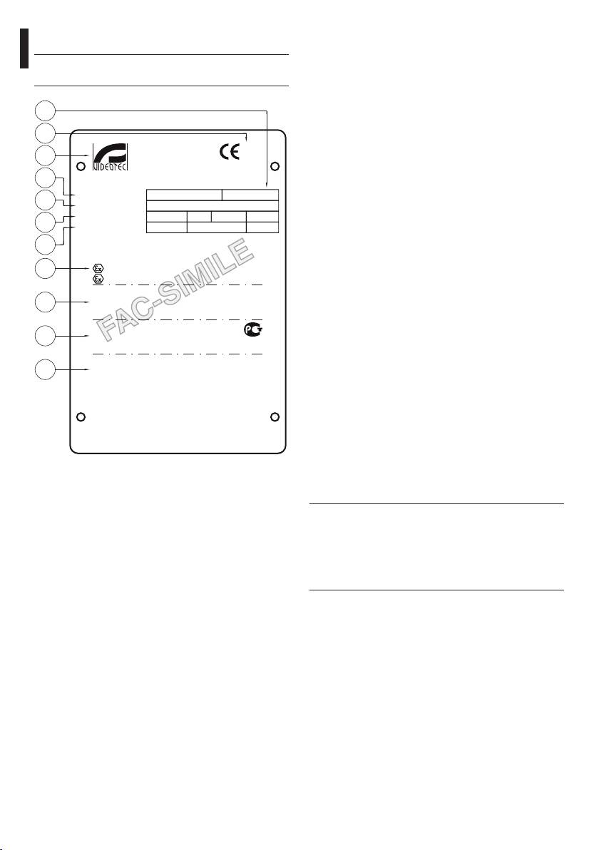
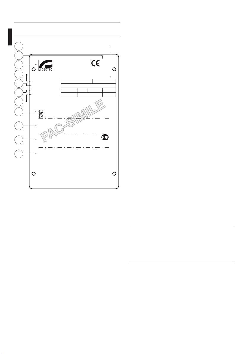
07. Camera:
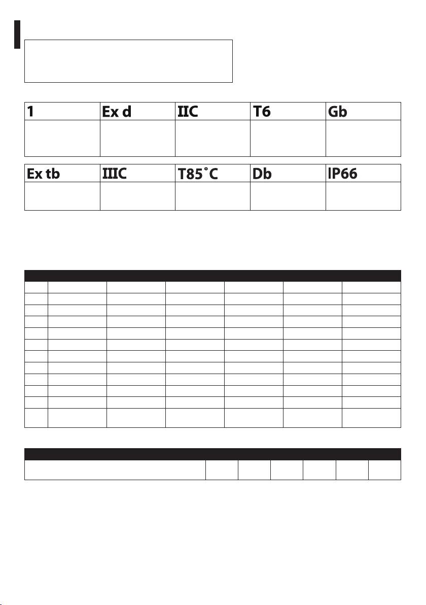
4.2 Product markings
• Power supply voltage (V)
Check the certifications on the data plate of
• Maximum power consumption (W) - (the data
h
the product you have purchased.
for the camera refer to the voltage specification
and maximum allowed power consumption for
04
camera operation)
08. ATEX certification:
01
VIDEOTEC S.p.A.
• ATEX certificate number
Via Friuli, 6
02
36015 Schio (VI)
0044
ITALY
• Classification for zone type, protection method,
www.videotec.com
03
temperature class for which this product may be
used in compliance with the ATEX directive
Model/Модель:
T
amb.
-20/+50 °C
05
Serial N°/Сер. №:
EN - English - Instructions manual
• CE mark and number of notified body that
Housing/Оболочка:
V
A
Hz
W
max
06
carries out production checks
Camera/Камера:
V
W
max
09. IECEx certification:
07
TÜV 04 ATEX 2584
• IECEx certificate number
08
ee 2G Ex d eeC T6 Gb
• Classification for zone type, protection method
ee 2D Ex t eeeC T85˚C Db IP66
and temperature class for which this product
IECEx TUN 05.0016
09
Ex d eeC T6 Gb
may be used in compliance with the IECEx
Ex t eeeC T85˚C Db IP66
standard
РОСС IT.ГБ05.В04259
10
10. GOST-R certification:
1 Ex d eeC T6 Gb
ГБ05
Ex tb eeeC T85˚C Db IP66
• GOST-R certificate number
CNEx 10.3140
11
Ex d eeC T6 Gb
• Classification for zone type, protection method
DIP A21 TA T6
and temperature class for which this product
WARNING - DO NOT OPEN WHEN ENERGIZED
may be used in compliance with the GOST-R
ПРЕДУПРЕЖДЕНИЕ - НЕ ОТКРЫВАТЬ ПРИ ПОДКЛЮЧЕННОМ ПИТАНИИ
CAUTION - USE FASTENERS WITH YIELD STRESS ≥ 700 N/mm^2
STANDARD
ОСТОРОЖНО – СЛЕДУЕТ ИСПОЛЬЗОВАТЬ ВИНТЫ С ПРЕДЕЛОМ ТЕКУЧЕСТИ ≥ 700 N/mm^2
USE STAINLESS STEEL SCREWS, TYPE A2 UNI 5931, DIN 912
ИСПОЛЬЗОВАТЬ ВИНТЫ ИЗ НЕРЖАВЕЮЩЕЙ СТАЛИ, ТИП A2 UNI 5931, DIN 912
11. Chinese certification:
MADE IN ITALY
• CNEx certificate number
• Classification of the type of area, the protection
Fig. 02 Example of data plate.
method and the temperature range the product
01. CE symbol
can be used in according to Chinese standards
02. Manufacturer’s name and address
Before installation, make sure the power
03. Model identification code
h
supply and protection specifications of the
device correspond to those in the original
04. Ambient temperature of use referring to
order. Use of unsuitable appliances can
model identification code
cause serious hazards, risking the safety of
05. Serial number
personnel and of the installation.
06. Housing:
• Power supply voltage (V)
• Absorption current (A)
• Frequency (Hz)
• Housing power consumption (W)
8

5 Preparing the product
6 Installing and
for use
assembling
EN - English - Instructions manual
Any change that is not expressly approved
Only specialised personnel should be
h
by the manufacturer will invalidate both
h
allowed to install and assemble the device.
the guarantee and certification.
6.1 Assembly
No special requirements are demanded
j
from those in charge of handling; therefore
6.1.1 Range of use
follow normal accident prevention
The EXH housing is designed for use in a fixed
regulations when carrying out this
location, for surveillance of areas with class 1-21 or
operation.
class 2-22 potentially explosive atmospheres, using a
camera/lens installed inside the housing by the user.
5.1 Safety precautions before
The EXH housing is made and certified in compliance
with the 94/9/CE ATEX Directive, the IECEx
use
international Standard, GOST-R STANDARDS, and
The following procedures should be carried
Chinese standards, which define the application field
g
out with the power supply disconnected,
and the minimum safety requirements.
unless indicated otherwise. An appropriate
The housings for thermal imaging cameras have been
protection device should be installed in
built and certified in compliance with ATEX directive
the electrical equipment upstream of the
94/9/CE and with the GOST-R STANDARD, which
device.
define the range of application and minimum safety
requirements.
Never exceed performance specifications.
6.1.2 Specification of maximum values
o
Do not replace the housing screws with
when installing cameras, including lens
other kinds of screw. Make all connections
in a non-explosive atmosphere.
The housing and the heating system must
g
use the same power supply.
The device must be installed only
h
and exclusively by qualified technical
The installer should never use devices
personnel. Make connections and tests
h
that do not remain within the specified
in the laboratory before carrying out
maximum values.
installation on site. Use appropriate tools
for the purpose.
• Camera: Analogue or network camera
• Maximum power: 20W
5.2 Contents and unpacking
• Maximum voltage: 240Vac
When the product is delivered, make sure that the
• Usable volume for camera/lens: 2800cm
package is intact and that there are no signs that it
• Minimum distance between the walls of the
has been dropped or scratched.
housing and the camera/lens: 12mm
If there are obvious signs of damage, contact the
supplier immediately.
Keep the packaging in case you need to send the
product for repairs.
Check the contents to make sure they correspond
with the list of materials as below:
• 1 explosion-proof housing
• 1 gasket kit
• 1 instructions manual
9
6.2 Installation
6.2.2 Changing the back cover gasket
If the back cover gasket of the housing is worn it
The installer must not use devices that
should be replaced using the supplied spare or,
h
generate dangerous radiation.
failing that, using only and exclusively a VIDEOTEC
original part.
The back flange of the housing has 12 stainless
When changing the gasket, take care to make sure it
steel A2-type M6 screws. It also has 3 screws at 120°
is properly inserted in its seating.
intervals to facilitate extraction of the flange. When
the M6-thread screws have been unscrewed from
Reconnect the earth wires that had been
the flange, turning the 3 screws at 120° (one turn per
disconnected in order to extract the flange.
screw at a time, in turn) will make it easier to extract
Close the flange properly, using a torque wrench
the flange.
setting of 12.5Nm when tightening the 12 screws.
EN - English - Instructions manual
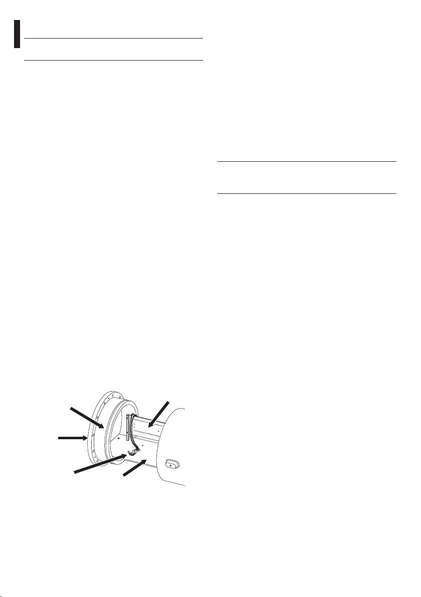
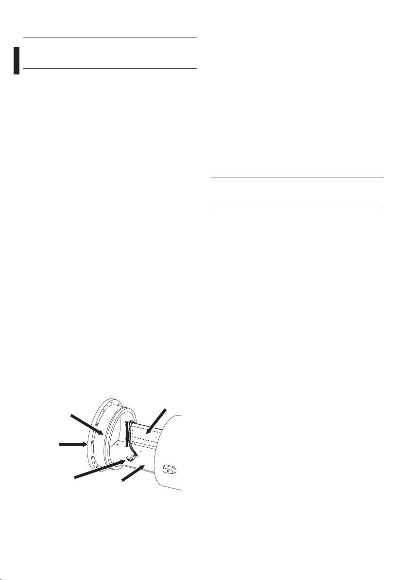
6.2.1 Installing the camera
6.3 Operational test
To install the camera, you have to extract the flange
closing the housing, which also supports the plate to
Before proceeding with the following
which the camera will be attached, and the related
h
operations, make sure that the mains
terminal board. This plate is supported on two guides
voltage is correct.
attached to the housing; when the flange is removed,
the plate slides along the guides, so that it is easy to
To connect the housing to the main power supply
fit and connect the camera and its accessories. During
use cables designed for use in potentially explosive
installation, we strongly recommend insulating the
atmospheres, and proceed as follows:
camera from the support plate using the supplied
• Choose and install cable glands that are suitable
insulating spacers.
for the housing marking and the type of
(To identify the parts, see the illustration below and
atmosphere present (EN/IEC60079-14);
the attached electrical diagram).
• Fasten the cable gland using a torque setting
Before closing the flange, after installing the
which guarantees that at least five threads are
camera, make sure that the 4 earth wires have been
engaged;
connected (back cover, front cover, housing body,
• Use cables that are suitable for the selected cable
terminal board) and make sure they have been
glands;
placed at the same potential.
• Make the connections with the camera and lens;
We recommend a torque wrench setting of 12.5Nm
• Power the unit;
for the 12 screws closing the flange.
• Carry out the operational tests.
The appropriate joint is used to install the housing.
It has 4xM6 holes at 90° intervals, and, where
appropriate, a bracket which is attached using the
4xM8 holes.
Back cover
Terminal board
gasket
Flange
Earth
connection
Fixing plate
Fig. 03
10

7 Instructions for safe
8 Maintaining and cleaning
operation
Before doing any technical work on the
EN - English - Instructions manual
h
device, disconnect the power supply.
7.1 Safe operation
8.1 Maintenance and cleaning
Before proceeding with the following
g
operations, make sure that the mains
by users
voltage is correct.
8.1.1 Routine (to be carried out
7.1.1 Commissioning
regularly)
• Read the whole of this user’s handbook very
• Cleaning the glass: Water should be used, or a
carefully;
liquid detergent that will not generate a hazardous
situation;
• Install the camera and lens correctly;
• Cleaning the germanium window: Use neutral
• Test system operation for positive results;
soap diluted with water; take extra care not to
• Prepare an appropriate power supply line.
scratch or damage the outer surface treated with
7.1.2 Safety rules
carbon coating. Damage to this coating could also
interfere with the transparency of the surface to
• Given the considerable weight of the system, use
infrared light. Do not use ethyl alcohol , solvents,
an appropriate transport and handling system.
hydrogenated hydrocarbons, strong acids or
• Before starting any operation, make sure the
alkalis. Using these products will irreparably
power supply is disconnected;
damage the germanium surface.
• Before powering the system, install an overload
• Cleaning the device: This should be done
protection device in the electrical equipment for
regularly; if a layer of dust accumulates on the
the building.
outside of the housing, it should never be more
• Make sure that all precautions for personal safety
than 5mm thick. The device should be cleaned
have been taken;
using a damp cloth; compressed air must not be
used. Maintenance frequency will depend on the
• Installation of the electrical equipment must
type of environment in which the housing is used.
comply with the local legislation in force.
• Inspecting the cables: The cables should not
7.1.3 Explosion prevention rules
show signs of damage or wear, which could
• Choose a solid, stable support surface;
generate hazardous situations; in this case
• Choose an appropriate support bracket, if used;
extraordinary maintenance is necessary.
• Use appropriate tools for the area in which you are
• Changing the Mylar tape (version with glass
working;
protection device): To carry out this operation,
the minimum safety conditions indicated in "7
• Do not open the housing if there is a possibility of
Instructions for safe operation", page 11 must be
your being in a potentially explosive atmosphere.
ensured. To proceed, loosen the 4 fixing screws on
• Use safe, long-lasting screws or other anchorage
the glass protection cover, then simply remove the
systems.
rollers with the dirty belt and replace them with
the rollers with clean belt.
Always remember that the unit must
o
be connected to an appropriate earth
conductor.
After commissioning the system keep this
h
handbook in a safe place, available for later
consultation.
11

• Opening the housing to change the camera:
8.2 Spare parts
Check the condition of the back cover gasket of
the housing; if it needs changing use only the one
To order the spare parts it is necessary to
supplied with the housing or, failing that, use only
j
provide the serial number of the product on
VIDEOTEC original spare parts ("6.2.2 Changing the
which the intervention is to be carried out
back cover gasket", page 10).
(explosionproof@videotec.com).
8.1.2 Extraordinary (to be done only
8.3 Repairs
under particular circumstances)
• Changing the front unit with glass (or the glass
For any other maintenance intervention the
protection unit when present).
j
housing must be sent to VIDEOTEC, subject
• Changing the inner slide unit with heater wiring
to a request for return authorisation
and electrical connection board, using the
(techsupport@videotec.com).
EN - English - Instructions manual
appropriate spare part for versions with or without
the glass protection device.
9 Disposal of waste
• Hazardous wear or damage to cables.
• Camera or lens failure.
materials
• Explosion in or near the housing.
This symbol mark and recycle system
• Any other situation in which the housing has to be
are applied only to EU countries and not
opened.
n
applied to the countries in the other area of
the world.
For damage to any parts that are not
h
indicated above, repair or replacement
Your product is designed and manufactured with
must be done by VIDEOTEC.
high quality materials and components which can be
recycled and reused.
Whenever replacing the parts as indicated,
This symbol means that electrical and electronic
h
always use VIDEOTEC original spare parts
equipment, at their end-of-life, should be disposed of
and meticulously follow the maintenance
separately from your household waste.
instructions supplied with every spare parts
kit.
Please dispose of this equipment at your local
Community waste collection or Recycling centre.
The manufacturer declines all liability for
In the European Union there are separate collection
h
damage to any of the apparatus mentioned
systems for used electrical and electronic products.
in this handbook, when resulting from
tampering, use of non-original spare parts,
and from installation and maintenance/
repairs performed by non-authorised, non-
skilled personnel.
In all such circumstances, the housing
j
should be sent to the workshop for the
necessary repairs or maintenance.
12

Devices to install inside the housing
10 Technical data
Camera: Analogue or network camera
Camera equipped with lens with maximum total power:
10.1 General
EN - English - Instructions manual
20W
Non-corrosive die-cast aluminium (anticorodal)
Maximum voltage: 240Vac (24Vac or 230Vac versions)
Bicomponent polyurethane enamel with orange peel
3
Usable volume for camera/lens: 2800cm
effect, RAL7032
Minimum distance between the walls of the housing and
Special painting, blue colour RAL7001. Resistant to stress
the camera/lens: 12mm
cracking, adverse weather conditions, detergents, salt-
spray and typical airborne pollutants
10.4 Accessories
10.2 Mechanical
EXHS000 Sunshield 650mm for EXHC
EXHS001 Sunshield 760mm for EXHD
2 holes for cable glands 3/4" NPT
OCTEX3/4C Cable gland with gasket EX
External dimensions
3/4" NPT unarmoured cable
EXHC Ø 210mmx427.5mm
IECEX-ATEX-GOST
(8.2x16.8in)
OCTEXA3/4C Cable gland with gasket EX
EXHD Ø 250x573.5mm (9.8x 22.6in)
3/4" NPT armoured cable
Internal dimensions
IECEX-ATEX-GOST
EXHC Ø 180x380mm (7x14.9in)
OCTEXB3/4C Barrier cable gland EX 3/4"
NPT, anarmoured cable
EXHD Ø 180x460mm (7x 18.1in)
IECEX-ATEX-GOST
Internal usable area
OCTEXBA3/4C Cable gland with gasket EX
EXHC 100x100x280mm
3/4" NPT armoured cable
(3.9x3.9x11in)
IECEX-ATEX-GOST
EXHD 100x100x280mm
OCTEX3/4 Cable gland with gasket EX
(3.9x3.9x11in)
3/4" NPT unarmoured cable
Glass window
ATEX
EXHC Ø 114mm (4.5in)
OCTEXA3/4 Cable gland with gasket EX
3/4" NPT armoured cable
EXHD 70x56mm (2.7x2.2in)
ATEX
Device for the protection of the glass
OEXPLUG3/4 Plug EX 3/4" NPT IECEX-
Device for the protection of the glass Ø 250x140mm
ATEX-GOST
Mylar film 80mm (3.1in) wide and 18m (59ft) length, 350
shifting steps, marks printed on the last 50cm (19in)
10.5 Related products
Wall mount
EXWBJ000 Wall bracket and ball joint
Load rating: 35kg (77lb)
for EXH RAL7032
Length: 455mm (17.9in)
EXWBJ00R Wall bracket and ball joint
for EXH RAL7001
Parapet mount
EXBJ000 Ball joint for EXH RAL7032
Load rating: 35kg (77lb)
EXBJ00R Ball joint for EXH RAL7001
10.3 Electrical
10.6 Environment
Heater Ton 15°C +/-4°C Toff 22°C +/-3°C
Operating temperature with heater: -20°C / +50°C
IN 24Vac, consumption 20W max
Operating temperature with reinforced heater:
IN 230Vac, consumption 20W max (only for EXHC200)
-40°C / +50°C
Reinforced heater Ton 15°C +/-4°C Toff 22°C +/-3°C
Always refer to the temperature in the marking
IN 24Vac, consumption 20W max
3 resistors in the housing, consumption 60W max
Glass protection device
24Vac, consumption 2W max
13
OSLIEX Internal slide complete with
10.7 Compliance to
heater for EXHC
For each version, verify the existing certification:
OSLIEXD Internal slide complete with
IECEx (TUV Nord Certification), protocols IEC 60079-
heater for EXHD
0:2007, IEC 60079-1:2007, IEC 60079-31:2008
10.9 Package
ATEX (TUV Nord Certification), directive 94/9/CE
GOST-R (NANIO CCVE Certification)
Unit Weight:
Chinese certification (CNEx certification)
EXHC 15kg / 33lb
EXHD 24kg / 52.9lb
10.8 Spare parts list
Package Weight:
OEXGOM Gaskets for cable glands Ex
EXHC 17.5kg / 38.6lb
d 3/4" NPT IP66 ATEX not
EXHD 24kg / 52.9lb
armored
EN - English - Instructions manual
Package Dimensions (BxHxL):
OEXVET Front flange complete with
glass for EXHC RAL7032
EXHC 61x32x31cm /
24x12.6x12.2in
OEXDPV Front flange complete with
glass protection device for
EXHD 43x67x67cm /
EXHD RAL 7032
16.9x26.3x26.3in
OEXMYLAR Mylar film replacement kit,
18m (59ft) 350 steps
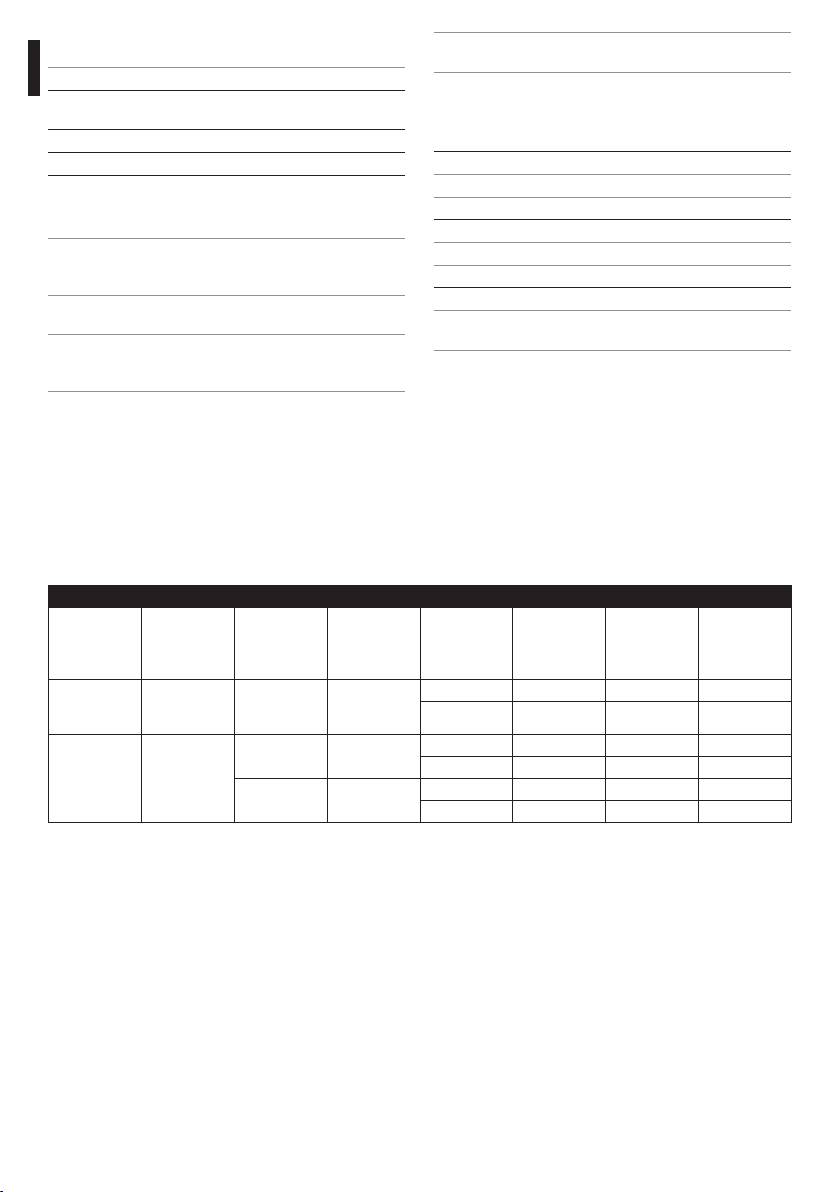
10.10 Cable glands
CABLE GLANDS SELECTION TABLE
Zone - Gas Cable gland
Certification Operating
Cable Cable glands
External
Diameter
type
temperature
part code
diameter
under
(mm)
armour
(mm)
IIC Zone 1 or
Barrier IECEX / ATEX /
-60 / +80°C
Not armored OCTEXB3/4C 13 - 20.2 -
Zone 2
GOST
-76 / 176°F
Armored OCTEXBA3/4C 16.9 - 26 -
IIB or IIA Zone 1
IIB or IIA Zone 2 With gasket IECEX / ATEX /
-60 / +100°C
Not armored OCTEX3/4C 13 - 20.2 -
GOST
-76 / 212°F
Armored OCTEXA3/4C 16.9 - 26 11.1 - 19.7
ATEX -20 / +80°C
Not armored OCTEX3/4 14 - 17 -
-4 / 176°F
Armored OCTEXA3/4 18 - 23 14 - 17
Tab. 01
14
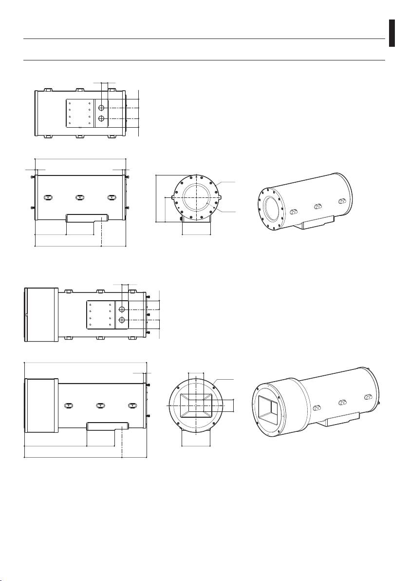
11 Technical drawings
The values are in millimeters.
EN - English - Instructions manual
j
30
41 50 41
428
12 12
Ø 210
220
Ø 114
115
147
130
132
312
116
Fig. 04 EXHC
30
5041 41
574
12
70
Ø 250
56
293
130
132
458
116
Fig. 05 EXHD
15
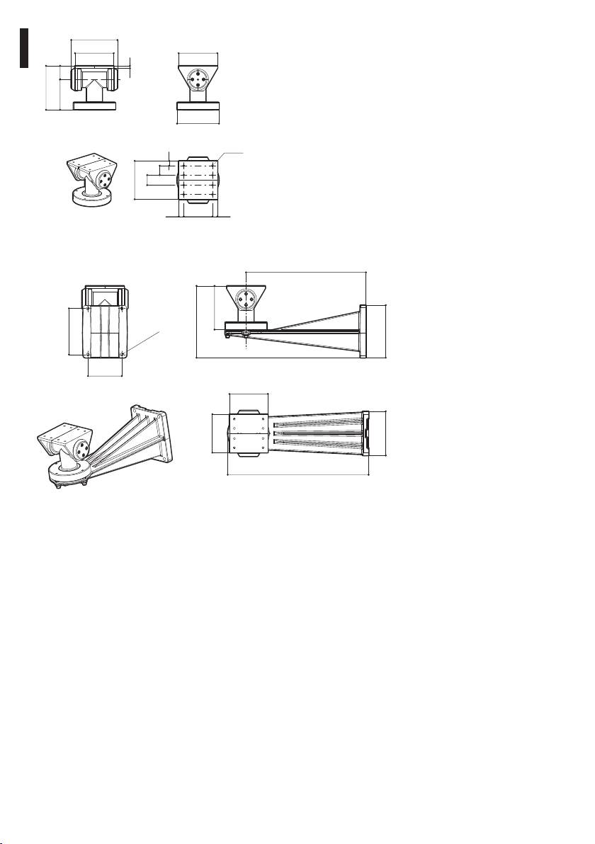
150
125
125
8
4498
142
Ø 135
Ø 6.4
16
30
125
33
EN - English - Instructions manual
16 1693
Fig. 06 EXBJ
390
142
233
150
Ø 11
170
110
125
125
144
458
Fig. 07 EXWBJ
16
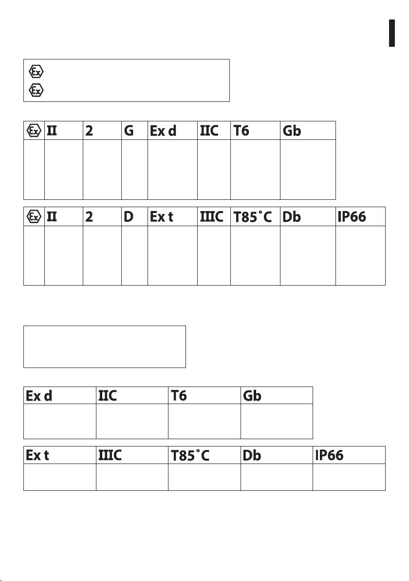
12 Appendix A - Marking codes
12.1 ATEX Mark
EN - English - Instructions manual
ee
2G Ex d eeC T6 Gb
ee
2D Ex t eeeC T85°C Db IP66
Fig. 08
Group (surface
Category (high
Gas Explosion-proof
Gas group Gas temperature
Protection level of the
device, no
protection
housing for potentially
classification
equipment for gas
mining)
degree, the
explosive environments
device in this
category can be
installed in zones
1 and 2)
Group (surface
Category (high
Dust Dust ignition protection
Dust group Maximum surface
Protection level of the
IP protection degree
device, no
protection
for zone types 21-22
temperature for dusts
equipment for dust
mining)
degree, the
device in this
category can be
installed in zones
21 and 22)
Tab. 02
12.2 IECEx Mark
Ex d eeC T6 Gb
Ex t eeeC T85°C Db IP66
Fig. 09
Explosion-proof
Gas group Gas temperature
Protection level of the
housing for
classification
equipment for gas
potentially explosive
environments
Dust ignition
Dust group Maximum surface
Protection level of the
IP protection degree
protection for zone
temperature for dusts
equipment for dust
types 21-22
Tab. 03
17
12.3 GOST-R Mark
1 Ex d eeC T6 Gb
Ex tb eeeC T85˚C Db IP66
Fig. 10
Protection level Explosion-proof
Gas group Gas temperature
Protection level of the
housing for
classification
equipment for gas
potentially explosive
EN - English - Instructions manual
environments
Dust ignition
Dust group Maximum surface
Protection level of the
IP protection degree
protection for zone
temperature for dusts
equipment for dust
types 21-22
Tab. 04
12.4 Gas group classification
The table below shows the classification of some gases and vapours, according to the explosion-proof
protection group and the temperature class. For a complete list see IEC/EN 60079-12 and IEC/EN 60079-20.
T1 T2 T3 T4 T5 T6
IIA Acetone N-Butane Petrol Acetaldehyde Ethyl nitrate
Ethanol N-Butyl Diesel fuel Ether
Ethyl acetate Avgas
Ammonia Heating oil
Pure benzene N-Hexane
Acetic acid
Carbon monoxide
Methanol
Propane
Toluene
IIB Ethylene
IIC Hydrogen Acetylene Carbon
disulphide
Tab. 05 The above temperature classes automatically cover the lower classes (T6 is better than T1).
Class IIB also covers class IIA. Class IIC also covers classes IIB and IIA.
TEMPERATURE CLASS T1 T2 T3 T4 T5 T6
Maximum allowed surface temperature (°C) for the
450 300 200 135 100 85
housing* in the corresponding class
Tab. 06 * Normally refers to the maximum ambient temperature of the installation. The lower the ignition temperature of the related
explosive atmosphere, the higher should be the maximum allowed surface temperature of the housing.
The maximum surface temperature is determined for a 5mm-thick layer of powder and the installation
regulations require a margin of 75K between the surface temperature and the ignition temperature of the
powder under consideration.
18
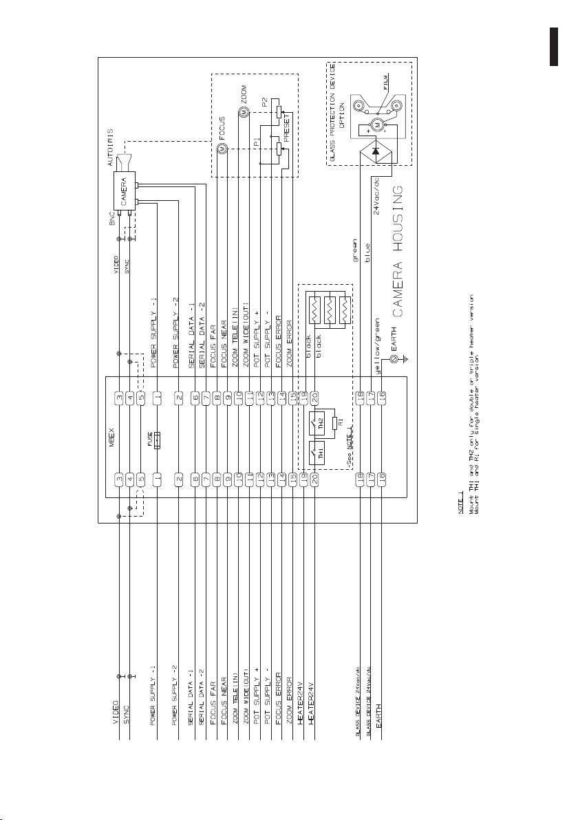
13 Appendix B - Electrical diagram
EN - English - Instructions manual
Fig. 11
19

14 Appendix C - EXH Declaration
EN - English - Instructions manual
20


VIDEOTEC S.p.A.
www.videotec.com
Printed in Italy
MNVCEXH_1307_EN
EXH
Custodia antideflagrante
IT
Italiano - Manuale di istruzioni
ITALIANO

Numero seriale
Trascrivere il numero di serie del prodotto e degli eventuali ricambi utilizzati.
Il numero seriale è riportato nell'etichetta presente all'esterno dell'imballo del prodotto e sulla
j
targhetta metallica di marcatura.
Codice Numero seriale

Sommario
ITALIANO
1 Informazioni sul presente manuale ............................................................................ 5
1.1 Convenzioni tipografiche .................................................................................................................................... 5
IT - Italiano - Manuale di istruzioni
2 Note sul copyright e informazioni sui marchi commerciali ...................................... 5
3 Norme di sicurezza ....................................................................................................... 5
4 Identificazione .............................................................................................................. 7
4.1 Descrizione e designazione del prodotto ..................................................................................................... 7
4.1.1 Versione per telecamere termiche ................................................................................................................................... 7
4.1.2 Versione con dispositivo protezione vetro ................................................................................................................... 7
4.2 Marcatura del prodotto ........................................................................................................................................ 8
5 Preparazione del prodotto per l'utilizzo .................................................................... 9
5.1 Precauzioni di sicurezza prima dell'utilizzo................................................................................................... 9
5.2 Contenuto e disimballaggio ............................................................................................................................... 9
6 Installazione e assemblaggio ...................................................................................... 9
6.1 Assemblaggio .......................................................................................................................................................... 9
6.1.1 Campo di utilizzo .................................................................................................................................................................... 9
6.1.2 Specifiche massime delle telecamere comprese di ottica installabili ................................................................. 9
6.2 Installazione ...........................................................................................................................................................10
6.2.1 Installazione della telecamera ......................................................................................................................................... 10
6.2.2 Sostituzione guarnizione fondo posteriore ................................................................................................................ 10
6.3 Verifica di funzionamento .................................................................................................................................10
7 Istruzioni di funzionamento in sicurezza .................................................................11
7.1 Funzionamento in condizioni di sicurezza .................................................................................................. 11
7.1.1 Messa in servizio ................................................................................................................................................................... 11
7.1.2 Prescrizioni di sicurezza .....................................................................................................................................................11
7.1.3 Prescrizioni di prevenzione di esplosione ................................................................................................................... 11
8 Manutenzione e pulizia.............................................................................................. 11
8.1 Manutenzione e pulizia da parte degli utilizzatori ...................................................................................11
8.1.1 Ordinaria (da eseguire periodicamente) ......................................................................................................................11
8.1.2 Straordinaria (da eseguire solo in casi particolari) ...................................................................................................12
8.2 Ricambi ....................................................................................................................................................................12
8.3 Riparazioni ..............................................................................................................................................................12
9 Smaltimento dei rifiuti ...............................................................................................12
10 Dati tecnici ................................................................................................................13
10.1 Generale ................................................................................................................................................................ 13
10.2 Meccanica ............................................................................................................................................................. 13
10.3 Elettrico .................................................................................................................................................................13
10.4 Accessori ...............................................................................................................................................................13
10.5 Prodotti Correlati ................................................................................................................................................13
10.6 Ambiente ..............................................................................................................................................................13
10.7 Conformità ...........................................................................................................................................................14
10.8 Lista Ricambi ........................................................................................................................................................14
3

10.9 Imballaggio .......................................................................................................................................................... 14
10.10 Pressacavi ...........................................................................................................................................................14
11 Disegni tecnici .......................................................................................................... 15
12 Appendice A - Codifica della marcatura .................................................................17
12.1 Marcatura ATEX ...................................................................................................................................................17
12.2 Marcatura IECEx .................................................................................................................................................. 17
12.3 Marcatura GOST-R ..............................................................................................................................................18
12.4 Classificazione gruppi gas ..............................................................................................................................18
13 Appendice B - Schema elettrico ..............................................................................19
14 Appendice C - Dichiarazione EXH ............................................................................20
IT - Italiano - Manuale di istruzioni
4
1 Informazioni sul presente
3 Norme di sicurezza
manuale
Il produttore declina ogni responsabilità
h
per eventuali danni derivanti da un
Prima di installare e utilizzare questa unità, leggere
uso improprio delle apparecchiature
attentamente questo manuale. Conservare questo
menzionate in questo manuale. Si
IT - Italiano - Manuale di istruzioni
manuale a portata di mano come riferimento futuro.
riserva inoltre il diritto di modificarne il
contenuto senza preavviso. Ogni cura é
1.1 Convenzioni tipografiche
stata posta nella raccolta e nella verifica
PERICOLO!
della documentazione contenuta in questo
g
Pericolosità elevata.
manuale, tuttavia il produttore non può
Rischio di scosse elettriche. Togliere
assumersi alcuna responsabilità derivante
l'alimentazione prima di procedere con le
dall’utilizzo della stessa. Lo stesso dicasi
operazioni, salvo diversa indicazione.
per ogni persona o società coinvolta nella
creazione e nella produzione di questo
manuale.
PERICOLO!
o
Pericolo di esplosione.
Leggere attentamente per evitare pericoli
Questo dispositivo deve essere collegato a
di esplosione.
h
terra.
ATTENZIONE!
h
Pericolosità media.
L'operazione è molto importante per il
corretto funzionamento del sistema. Si
prega di leggere attentamente la procedura
indicata e di eseguirla secondo le modalità
previste.
INFO
j
Descrizione delle caratteristiche del
sistema.
Fig. 01 Messa a terra.
Si consiglia di leggere attentamente per
• Assicurarsi che tutti i dispositivi siano adatti per
comprendere le fasi successive.
l’applicazione e l’ambiente per cui sono stati
progettati.
2 Note sul copyright e
• Assicurarsi che i dispositivi collegati siano
completamente compatibili e adatti all’uso.
informazioni sui marchi
• Controllare che le temperature di esercizio siano
commerciali
compatibili con i dispositivi.
I nomi di prodotto o di aziende citati sono marchi
• Accertarsi di installare i dispositivi in maniera
commerciali o marchi commerciali registrati
tale da garantire la sicurezza dell’impianto e del
appartenenti alle rispettive società.
personale addetto all’installazione.
• Scegliere la postazione di installazione in modo
che sia sufficientemente solida da sostenere il
peso del dispositivo, considerando anche aspetti
ambientali particolari come esposizione a vento
forte.
• Si raccomanda di utilizzare solo staffe o accessori
consigliate per l’installazione.
5

• Accertarsi che il dispositivo sia fissato in maniera
• Non permettere l’uso dell’apparecchio a bambini
solida ed affidabile.
o incapaci.
• Dato che la scelta della superficie di montaggio
• L’apparecchio si considera disattivato soltanto
è a cura dell’utente non si forniscono viti per il
quando l’alimentazione é disinserita e i cavi di
fissaggio sicuro del dispositivo alla superficie. È
collegamento con altri dispositivi sono stati
responsabilità dell’installatore utilizzare viti adatte
rimossi.
allo scopo specifico richiesto.
• Prima dell’alimentazione del dispositivo installare
• L’installazione e la manutenzione del dispositivo
un dispositivo di protezione nell’impianto elettrico
deve essere eseguita solo da personale tecnico
dell’edificio.
qualificato.
• Si raccomanda all’utente di non installare
• Utilizzare degli utensili adeguati. Degli utensili
all’interno del dispositivo qualsiasi apparecchiatura
specifici possono essere richiesti, per motivi
che generi radiazioni pericolose.
di installazione, in relazione al luogo in cui il
• Per l’assistenza tecnica rivolgersi esclusivamente al
dispositivo viene installato.
personale tecnico autorizzato.
• Assicurarsi che l’installazione soddisfi le specifiche
• Conservare con cura il presente manuale; deve
IT - Italiano - Manuale di istruzioni
locali.
essere a disposizione per eventuali consultazioni
• Questo dispositivo deve essere installato fuori dalla
nel luogo in cui viene eseguita l’installazione.
portata dell’utente o di chiunque ne possa entrare
• Non effettuare per nessun motivo alterazioni o
a contatto casualmente.
collegamenti non previsti in questo manuale:
• Prima di effettuare interventi tecnici
l’uso di apparecchi non idonei può portare a
sull’apparecchio togliere l’alimentazione elettrica.
gravi pericoli per la sicurezza del personale e
dell’impianto.
• Non utilizzare cavi di alimentazione con segni di
usura o invecchiamento.
• Utilizzare solo parti di ricambio VIDEOTEC.
• L’apparecchio deve essere aperto soltanto da
• Prima di procedere con l'installazione controllare
personale tecnico qualificato e in atmosfera non
che il materiale fornito corrisponda alle specifiche
esplosiva. La manomissione dell’apparecchio fa
richieste esaminando le etichette di marcatura ("4.2
decadere i termini di garanzia.
Marcatura del prodotto", pagina 8).
6

4.1.2 Versione con dispositivo
4 Identificazione
protezione vetro
4.1 Descrizione e designazione
Esiste una versione di custodia antideflagranti
della serie EXH con dispositivo di protezione vetro,
del prodotto
installato sull’apertura frontale della custodia.
La custodia antideflagrante della serie EXH è stata
Esso è costituito da una flangia di raccordo con
IT - Italiano - Manuale di istruzioni
progettata per consentire l’utilizzo di telecamere
la custodia, una flangia di chiusura e da un corpo
operanti in ambienti industriali in cui vi è la
centrale antideflagrante contenente un robusto
probabilità che si manifestino atmosfere esplosive
vetro trasparente, un motore in corrente continua
dovute a gas, vapori, nebbie o miscele di aria o
alimentato a 24Vdc, due avvolgitori ed una pellicola
polveri.
trasparente in Mylar, installata di fronte al vetro.
Le custodie EXH sono realizzate in massiccia fusione
Il motore, attraverso 4 pignoni conici dentati, pilota
in lega di alluminio Anticorodal del gruppo AlSi7Mg
un avvolgitore per il recupero della pellicola sporca,
EN AB-42000 la cui composizione chimica è definita
mentre l’altro avvolgitore rilascia la pellicola pulita.
dalla norma UNI EN 1706.
Il motore è controllato remotamente tramite un
contatto ON-OFF a due fili (un comune ed un +24Vac/
Secondo il modello, tutti gli elementi sono verniciati
Vdc, Fig. 11, pagina 19).
con polveri in forno o trattati con particolari
rivestimenti che offrono un’eccellente resistenza ai
L’unità di controllo del dispositivo
raggi ultravioletti, alla nebbia salina e agli agenti
h
protezione vetro è fornita dal cliente.
inquinanti presenti nell’atmosfera.
II corpo camera è costituito da un tubo cilindrico,
La pellicola di Mylar trasparente consente circa 350
dotato di flangia che alloggia un robusto vetro
passi di avanzamento.
trasparente; dalla parte opposta al vetro é presente
Infatti quando è sporca l’operatore attiverà il motore,
un’ulteriore flangia che, oltre a chiudere il cilindro,
facendo avanzare la pellicola sino ad ottenere
sostiene la piastra per il fissaggio della telecamera.
un’immagine pulita (il passo per consentire lo
La custodia presenta due fori per pressacavi 3/4" NPT.
scorrimento completo della pellicola sporca è di circa
50mm).
La scelta del pressacavo deve essere fatta secondo
quanto previsto dalla norma EN/IEC 60079-14.
La fine del nastro viene segnalata mediante
contrassegni stampati sugli ultimi 50cm di pellicola.
Tali pressacavi assicureranno il grado di protezione
IP66.
L’avanzamento della pellicola potrà avvenire anche
automaticamente in maniera temporizzata tramite
Si consiglia l'utilizzo di pressacavi
un opportuno sistema di controllo (escluso dalla
j
VIDEOTEC o equivalenti (Tab. 01,
fornitura).
pagina 14).
Per sostituire la pellicola fare riferimento al manuale
d'uso del ricambio Videotec (codice OEXMYLAR).
4.1.1 Versione per telecamere termiche
L’impiego di telecamere termiche, in grado di rilevare
l’emissione di calore, richiede l’utilizzo di uno speciale
filtro sul frontale della custodia. Questa custodia si
differenzia per la presenza di una finestra composta
in prevalenza da Germanio; esso garantisce le stesse
caratteristiche di resistenza e di sicurezza del vetro
standard. Campo di applicazione da 7.5 a 14µm.
7
07. Telecamera:
4.2 Marcatura del prodotto
• Tensione d’alimentazione (V)
Verificare le certificazioni nella targhetta
• Consumo massimo (W) – (i dati riportati per la
h
del prodotto acquistato.
telecamera si riferiscono alle caratteristiche di
tensione e consumo massimo ammesso per il
04
funzionamento della stessa)
08. Certificazione ATEX:
01
VIDEOTEC S.p.A.
• Numero del certificato ATEX
Via Friuli, 6
02
36015 Schio (VI)
0044
ITALY
• Classificazione del tipo di zona, metodo di
www.videotec.com
03
protezione, classe di temperatura per le quali è
ammesso l’impiego di questo prodotto secondo
Model/Модель:
T
amb.
-20/+50 °C
05
Serial N°/Сер. №:
la direttiva ATEX
Housing/Оболочка:
V
A
Hz
W
max
06
• Marcatura CE e numero dell’organismo
Camera/Камера:
V
W
max
notificato che effettua il controllo sulla
07
IT - Italiano - Manuale di istruzioni
produzione
TÜV 04 ATEX 2584
08
ee 2G Ex d eeC T6 Gb
09. Certificazione IECEx:
ee 2D Ex t eeeC T85˚C Db IP66
• Numero del certificato IECEx
IECEx TUN 05.0016
09
Ex d eeC T6 Gb
• Classificazione del tipo di zona, metodo di
Ex t eeeC T85˚C Db IP66
protezione e classe di temperatura per le quali è
РОСС IT.ГБ05.В04259
ammesso l’impiego di questo prodotto secondo
10
1 Ex d eeC T6 Gb
ГБ05
la normativa IECEx
Ex tb eeeC T85˚C Db IP66
CNEx 10.3140
10. Certificazione GOST-R:
11
Ex d eeC T6 Gb
DIP A21 TA T6
• Numero del certificato GOST-R
WARNING - DO NOT OPEN WHEN ENERGIZED
• Classificazione del tipo di zona, metodo di
ПРЕДУПРЕЖДЕНИЕ - НЕ ОТКРЫВАТЬ ПРИ ПОДКЛЮЧЕННОМ ПИТАНИИ
CAUTION - USE FASTENERS WITH YIELD STRESS ≥ 700 N/mm^2
protezione e classe di temperatura per le quali è
ОСТОРОЖНО – СЛЕДУЕТ ИСПОЛЬЗОВАТЬ ВИНТЫ С ПРЕДЕЛОМ ТЕКУЧЕСТИ ≥ 700 N/mm^2
USE STAINLESS STEEL SCREWS, TYPE A2 UNI 5931, DIN 912
ИСПОЛЬЗОВАТЬ ВИНТЫ ИЗ НЕРЖАВЕЮЩЕЙ СТАЛИ, ТИП A2 UNI 5931, DIN 912
ammesso l’impiego di questo prodotto secondo
MADE IN ITALY
gli STANDARD GOST-R
11. Certificazione cinese:
Fig. 02 Esempio di targa.
• Numero del certificato CNEx
01. Simbolo CE
• Classificazione del tipo di zona, metodo di
protezione e classe di temperatura per le quali è
02. Nome e indirizzo del costruttore
ammesso l’impiego di questo prodotto secondo
03. Codice di identificazione del modello
gli standard cinesi
04. Temperatura ambiente di utilizzo riferita al
Prima dell’installazione controllare se
codice di identificazione del modello
h
le caratteristiche di alimentazione e
05. Numero di serie
protezione del dispositivo corrispondono
06. Custodia:
a quelle richieste. L’uso di apparecchi non
• Tensione d’alimentazione (V)
idonei può portare a gravi pericoli per la
sicurezza del personale e dell’impianto.
• Corrente assorbita (A)
• Frequenza (Hz)
• Consumo custodia (W)
8

5 Preparazione del
6 Installazione e
prodotto per l'utilizzo
assemblaggio
Qualsiasi cambiamento non espressamente
L’installazione e l’assemblaggio vanno
h
approvato dal costruttore fa decadere la
h
eseguiti solo da personale specializzato.
IT - Italiano - Manuale di istruzioni
garanzia e la certificazione.
6.1 Assemblaggio
Per la movimentazione non sono richiesti
j
particolari requisiti da parte del personale
6.1.1 Campo di utilizzo
addetto, pertanto, si raccomanda di
L’impiego della custodia EXH è definito per l’utilizzo
effettuare tale operazione osservando le
in postazione fissa per la sorveglianza di zone con
comuni norme di antinfortunistica.
atmosfera potenzialmente esplosiva classificate
1-21 o 2-22, mediante telecamera/ottica installata
5.1 Precauzioni di sicurezza
dall’utente al suo interno.
La custodia EXH è costruita e certificata in accordo
prima dell'utilizzo
con la direttiva 94/9/CE ATEX, allo standard
Le seguenti procedure sono da effettuare
internazionale IECEx, gli STANDARD GOST-R e gli
g
in assenza di alimentazione, se non
standard cinesi, che ne definiscono il campo di
diversamente indicato. Un dispositivo
applicazione ed i requisti minimi di sicurezza.
di protezione adeguato deve essere
Le custodie per telecamere termiche sono costruite e
installato nell’impianto elettrico prima del
certificate in accordo con la direttiva 94/9/CE ATEX e
dispositivo.
gli STANDARD GOST-R che ne definiscono il campo di
applicazione ed i requisiti minimi di sicurezza.
Non superare le prestazioni specificate. Non
6.1.2 Specifiche massime delle
o
sostituire le viti della custodia con altre di
telecamere comprese di ottica
tipo diverso. Eseguire tutte le connessioni
in atmosfera non esplosiva.
installabili
L’alimentazione della custodia deve
La fase di installazione deve essere
g
essere la stessa utilizzata per il sistema di
h
effettuata solo da personale tecnico
riscaldamento.
qualificato. Effettuare i collegamenti e
prove in laboratorio prima dell’installazione
Si raccomanda all’installatore di non
nel sito. Utilizzare degli utensili adeguati.
h
utilizzare dispositivi che eccedano dalle
specifiche.
5.2 Contenuto e disimballaggio
• Telecamera: Analogica o network camera
Alla consegna del prodotto verificare che l’imballo
sia integro e non abbia segni evidenti di cadute o
• Potenza massima: 20W
abrasioni.
• Tensione massima: 240Vac
In caso di evidenti segni di danno all’imballo
• Volume utile per telecamera/ottica: 2800cm
contattare immediatamente il fornitore.
• Distanza minima tra le pareti della custodia e la
Conservare l’imballo nel caso sia necessario inviare il
telecamera/ottica: 12mm
prodotto in riparazione.
Controllare che il contenuto sia rispondente alla lista
del materiale sotto indicata:
• 1 custodia antideflagrante
• 1 dotazione guarnizioni
• 1 manuale di istruzioni
9
6.2 Installazione
6.2.2 Sostituzione guarnizione fondo
posteriore
Si raccomanda all’installatore di non
In caso di deterioramento della guarnizione presente
h
utilizzare dispositivi che generino
nel fondo posteriore della custodia sostituirla
radiazioni pericolose.
utilizzando solo la guarnizione fornita in dotazione
o in mancanza di essa utilizzare solo ricambio
La flangia posteriore sulla custodia è dotata di 12 viti
VIDEOTEC.
M6 in acciaio inox tipo A2. Inoltre è dotata di 3 viti
disposte a 120° per facilitare l’estrazione della flangia
Sostituire la guarnizione prestando attenzione ad
stessa. Infatti una volta svitate dalla flangia le viti con
inserirla correttamente nell’apposita sede.
filetto M6, avvitando le 3 viti a 120° (un giro alla volta,
Ricollegare i cavi di terra precedentemente scollegati
a rotazione) si agevola l’estrazione della stessa.
per estrarre la flangia.
6.2.1 Installazione della telecamera
Chiudere correttamente la flangia con coppia di
serraggio delle 12 viti di chiusura pari a 12.5Nm.
Per installare la telecamera occorre estrarre la flangia
di chiusura della custodia, che supporta anche la
6.3 Verifica di funzionamento
IT - Italiano - Manuale di istruzioni
piastra di fissaggio della telecamera con la relativa
morsettiera. Questa piastra é appoggiata su due
Prima di effettuare le seguenti operazioni
guide fissate alla custodia; togliendo la flangia la
h
assicurarsi che la tensione della linea sia
piastra scorre sulle guide, consentendo di montare
corretta.
e collegare agevolmente la telecamera ed i suoi
componenti accessori. In fase di installazione si
Per effettuare il collegamento della custodia alla
raccomanda di isolare la telecamera dalla piastra di
linea utilizzare cavi adatti all’impiego in atmosfere
supporto utilizzando gli appositi distanziali isolanti
potenzialmente esplosive, eseguire le seguenti
forniti a corredo.
operazioni:
(Per i particolari fare riferimento all’immagine
• Scegliere e installare i pressacavi adeguati alla
riportata di seguito e allo schema elettrico in
marcatura della custodia e al tipo di atmosfera
appendice).
presente (EN/IEC60079-14);
Prima di chiudere la flangia, dopo l'installazione della
• Fissare il pressacavo con una coppia di serraggio
telecamera, verificare di aver collegato i 4 cavi di terra
tale da garantire un numero minimo di filetti in
(fondo posteriore, fondo anteriore, corpo custodia,
presa pari a cinque;
morsettiera) e assicurarsi che siamo posti allo stesso
• Utilizzare cavi adeguati ai pressacavi scelti;
potenziale.
• Effettuare i collegamenti con la telecamera e ottica;
Si raccomanda una coppia di serraggio delle 12 viti di
chiusura pari a 12.5Nm.
• Dare alimentazione all’unità;
Per installare la custodia viene utilizzato l’apposito
• Eseguire prove di funzionamento.
snodo, dotato di 4 fori M6 disposti a 90°, ed
eventualmente la staffa, che si fissa mediante 4 fori
M8.
Guarnizione
Morsettiera
fondo
Flangia
Messa
a terra
Piastra di fissaggio
Fig. 03
10

7 Istruzioni di
8 Manutenzione e pulizia
funzionamento in sicurezza
Prima di effettuare interventi tecnici
h
sull’apparecchio togliere l’alimentazione
7.1 Funzionamento in condizioni
elettrica.
IT - Italiano - Manuale di istruzioni
di sicurezza
8.1 Manutenzione e pulizia da
Prima di effettuare le seguenti operazioni
parte degli utilizzatori
g
assicurarsi che la tensione della linea sia
corretta.
8.1.1 Ordinaria (da eseguire
periodicamente)
7.1.1 Messa in servizio
• Pulizia del vetro: Deve essere fatta con acqua o
• Leggere attentamente e completamente il
con altro liquido detergente che non crei situazioni
presente manuale d’uso;
di pericolo.
• Installare correttamente la telecamera e ottica;
• Pulizia finestra Germanio: Deve essere
• Controllare il funzionamento del sistema con esito
fatta con sapone neutro diluito con acqua;
positivo;
prestare attenzione a non graffiare o rigare la
• Predisporre una linea di alimentazione adeguata.
superficie esterna trattata con carbon coating.
Danneggiando tale rivestimento c'è il rischio di
7.1.2 Prescrizioni di sicurezza
compromettere la trasparenza all’infrarosso della
• Dato il peso considerevole del sistema è necessario
superficie. Sono da evitare alcool etilico, solventi,
utilizzare un adeguato sistema di trasporto e
idrocarburi idrogenati, acidi forti e alcali. L’utilizzo
movimentazione;
di detti prodotti danneggia in modo irreparabile la
superficie del germanio.
• Assicurarsi di avere scollegato l’alimentazione
prima di eseguire qualsiasi operazione;
• Pulizia dell’apparecchio: Deve essere eseguita
periodicamente; non ci deve essere mai depositato
• Prima dell’alimentazione del sistema, installare un
nella custodia un accumulo di polvere superiore
dispositivo di protezione nell’impianto elettrico
ai 5mm sulla superficie esterna. La pulizia deve
dell’edificio;
essere effettuata con un panno umido e senza
• Assicurarsi di aver preso tutte le prescrizioni di
l’utilizzo di aria compressa. La frequenza di
sicurezza riguardo l’incolumità del personale;
interventi di manutenzione dipende dalla tipologia
• L’installazione elettrica dell’impianto deve essere
dell’ambiente in cui è utilizzata la custodia.
conforme alle norme locali vigenti.
• Controllo dei cavi: I cavi non devono presentare
7.1.3 Prescrizioni di prevenzione di
segni di usura o deterioramento tali da creare
situazioni di pericolo, in questo caso si deve
esplosione
eseguire una manutenzione straordinaria.
• Scegliere una superficie di appoggio solida e
• Sostituzione del nastro in Mylar (versione con
stabile;
dispositivo di protezione vetro): Deve essere
• Scegliere una adeguata staffa di sostegno, se
eseguita nelle minime condizioni di sicurezza
utilizzata;
indicate nel "7 Istruzioni di funzionamento in
• Utilizzare utensili idonei alla zona in cui si opera;
sicurezza", pagina 11. È possibile eseguire questa
operazione svitando le 4 viti di fissaggio del
• Non aprire la custodia se vi è la possibilità di
coperchio della protezione vetro per sostituire i
presenza di atmosfera potenzialmente esplosiva;
rullini con il nastro sporco con quelli con il nastro
• Utilizzare viti o altri sistemi di fissaggio sicuri e
pulito con un semplice sfilamento.
duraturi.
Si ricorda che l’unità deve essere collegata
o
ad una connessione di terra elettrica
adeguata.
Dopo la messa in servizio archiviare il
h
presente manuale d’uso per consultazioni
successive.
11
")