Videotec MAXIMUS WASEX: инструкция
Раздел: Видеотехника
Тип:
Инструкция к Videotec MAXIMUS WASEX
WASEX
Explosion-proof stainless steel wiper and washer pump
for MAXIMUS series
EN
English - Instructions manual
IT
Italiano - Manuale di istruzioni
FR
Français - Manuel d’instructions
DE
Deutsch - Bedienungslanleitung
RU
-
Руководство по эксплуатации
ENGLISHITALIANOFRANÇAISDEUTSCH
РУССКИЙ

ENGLISH
WASEX
Instructions manual - English - EN
Explosion-proof stainless steel wiper and washer pump for MAXIMUS series
1 About this manual
3 Safety rules
Before installing and using this unit, please read this
The manufacturer declines all responsibility
manual carefully. Be sure to keep it handy for later
for any damage caused by an improper use
reference.
of the appliances mentioned in this manual.
Furthermore, the manufacturer reserves
1.1 Typographical conventions
the right to modify its contents without any
prior notice. The documentation contained
DANGER!
in this manual has been collected with great
Explosion hazard.
care, the manufacturer, however, cannot
Read carefully to avoid danger of explosion.
take any liability for its use. The same thing
can be said for any person or company
DANGER!
involved in the creation and production of
High level hazard.
this manual.
Risk of electric shock. Disconnect the
power supply before proceeding with any
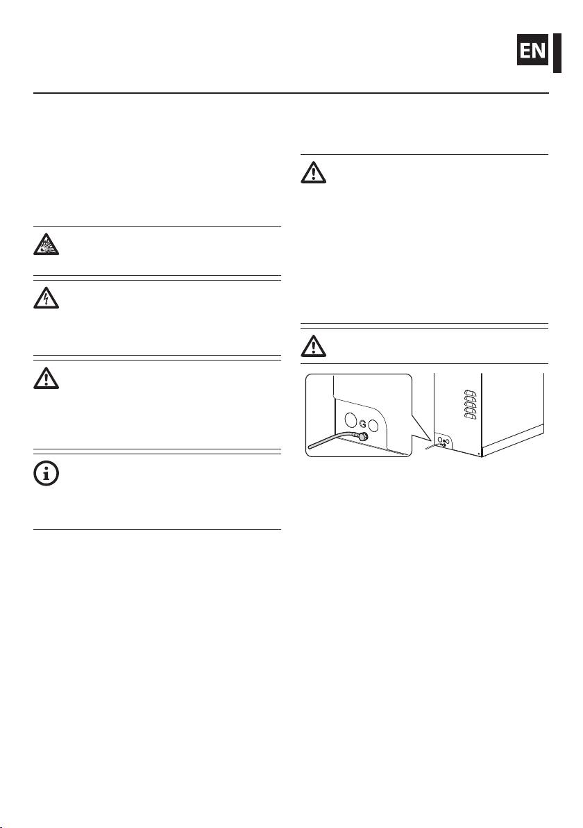
This device must be connected to the
operation, unless indicated otherwise.
ground as shown in the picture.
WARNING!
Medium level hazard.
This operation is very important for the
system to function properly. Please read
the procedure described very carefully and
carry it out as instructed.
INFO
Fig. 1
Description of system specications.
We recommend reading this part carefully
• Read these instructions.
in order to understand the subsequent
• Keep these instructions.
stages.
• Heed all warnings.
• Follow all instructions.
2 Notes on copyright and
• Make sure that all the devices are suitable for the
information on trademarks
application and for the environment in which they
will be installed.
The quoted names of products or companies are
trademarks or registered trademarks.
• Make sure that the connected devices are
completely compatible and suitable for use.
• Make sure the operating temperatures are
compatible with the devices.
1

• When installing the devices make sure the system
• The device can only be considered to be switched
and installer personnel are absolutely safe.
o when the power supply has been disconnected
and the connection cables to other devices have
• Choose an installation site that is strong enough
been removed.
to sustain the weight of the device, also bearing
in mind particular environmental aspects, such as
• Before powering the device install an overload
exposure to strong winds.
protection device in the electrical equipment for
the building.
• We strongly recommend using only approved
brackets and accessories during installation.
• For technical services, consult only and exclusively
authorized technicians.
• Make sure that the device is rmly anchored so
that it cannot become detached.
• Keep this handbook carefully; it must be available
for consultation on the installation site.
• Since the user is responsible for choosing the
surface to which the device is to be anchored,
• Never, under any circumstances, make any
EN - English - Instructions manual
we do not supply screws for attaching the device
changes or connections that are not shown in
rmly to the particular surface. The installer is
this handbook: improper use of the appliance
responsible for choosing screws suitable for the
can cause serious hazards, risking the safety of
specic purpose on hand.
personnel and of the installation.
• The device must be installed only and exclusively
• Use only VIDEOTEC original spare parts.
by qualied technical personnel.
• Before proceeding with installation check the
• Before any technical work on the appliance,
supplied material to make sure it corresponds
disconnect the power supply.
to the order specication by examining the
identication labels (4.2 Product markings, page 3).
• Do not use power supply cables that seem worn
or old.
• Only qualied technical personnel should be
allowed to open the device, and they should work
in a non-explosive atmosphere. Tampering with
the device will invalidate the guarantee.
2
The cable glands must be selected according to what
4 Identification
is indicated by the EN/IEC 60079-14 Standard.
These cable glands guarantee an IP66 protection
Instructions manual - English - EN
4.1 Product description and type
level.
designation
We recommend using VIDEOTEC cable
The WASEX washer pump is built with a stainless
glands or equivalent (Tab. 2, page11).
steel AISI 316L enclosure which guarantees excellent
corrosion resistance both in industrial and seaside
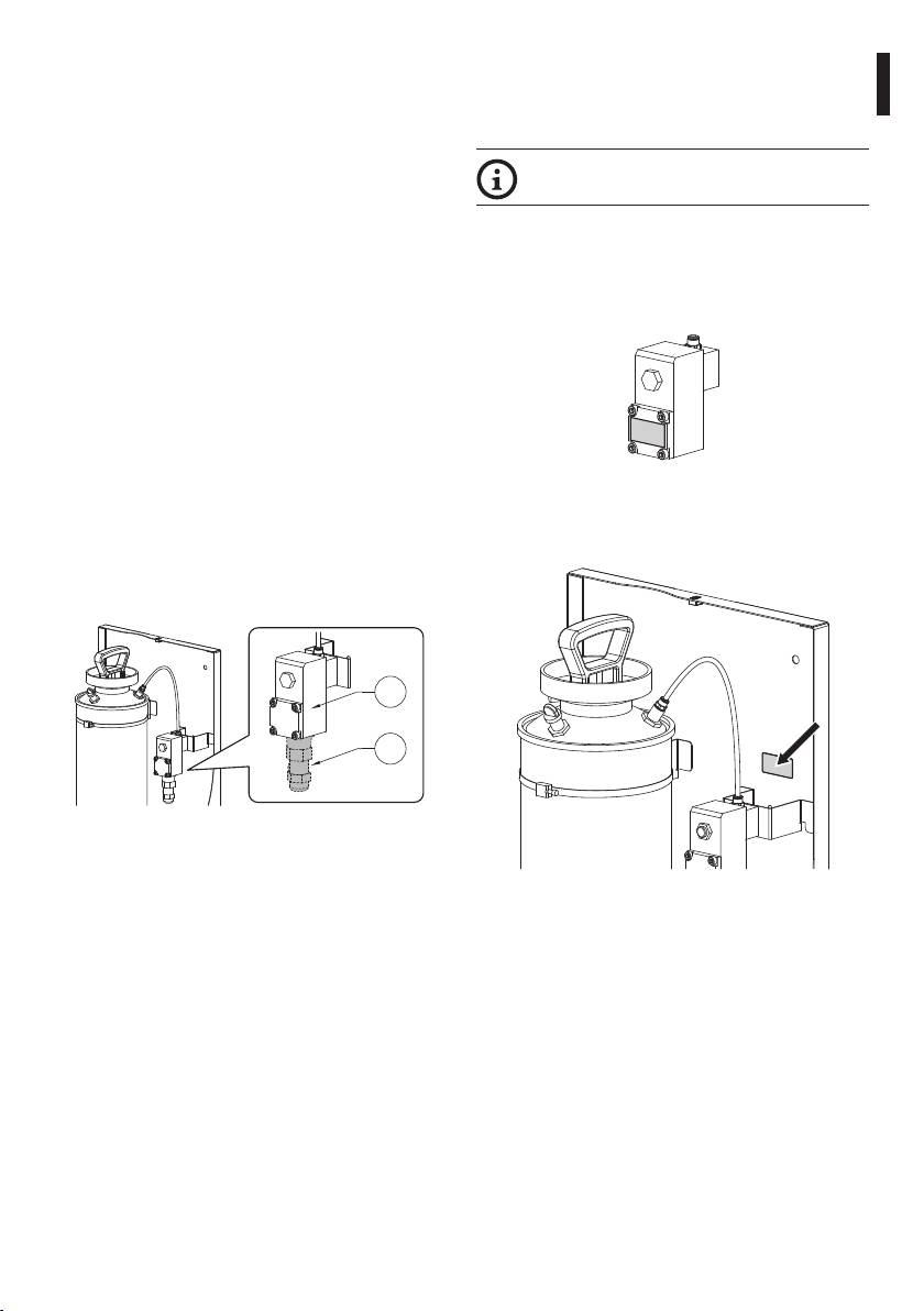
4.2 Product markings
areas.
The marking on the glass washer pump relates to the
The system guarantees complete cleaning of glass on
marking on the solenoid valve. The marking plate is
the MAXIMUS devices.
tted on the solenoid valve.
The articulated nozzle of the pump can be adjusted
in order to associate to a preset, in the desired
position, the wiper and spray functions.
The pump is controlled by an explosion-proof
solenoid-valve which provides liquid passage and
by the MAXIMUS pan & tilt telemetry or by a manual
electric contact.
The tank has a 10 litre capacity and can be lled
Fig. 3
with an integrated hand pump or by means of other
The product serial number is indicated in the label
devices depending on the user's requirements.
positioned as shown in the gure.
The system is available in 24Vac/dc.
The solenoid valve (01) has a hole for a ½” NPT cable
gland (02).
01
02
Fig. 2
Fig. 4
3
5 Preparing the product for
5.2 Unpacking and contents
use
5.2.1 Unpacking
When the product is delivered, make sure that the
Any change that is not expressly approved
package is intact and that there are no signs that it
by the manufacturer will invalidate the
has been dropped or scratched.
guarantee.
If there are obvious signs of damage, contact the
supplier immediately.
No special requirements are demanded
from those in charge of handling; therefore
Keep the packaging in case you need to send the
follow normal accident prevention
product for repairs.
regulations when carrying out this
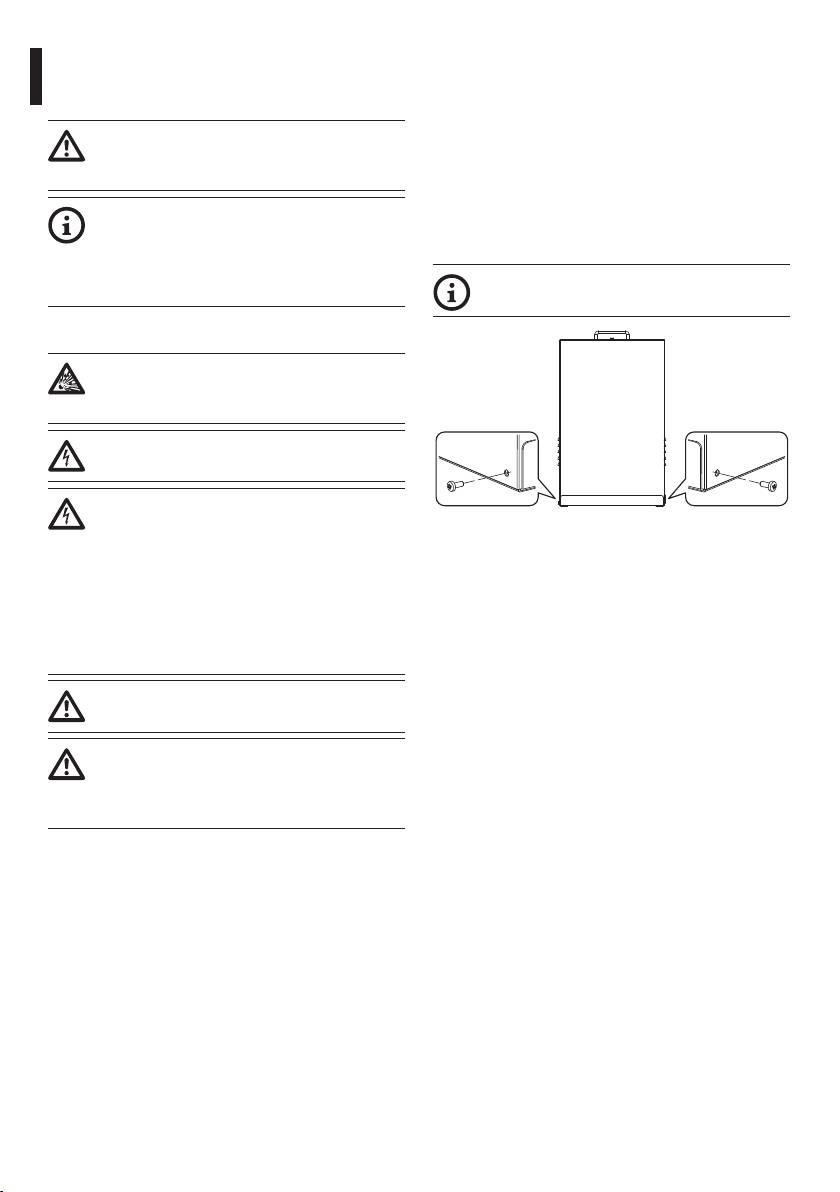
Unscrew the 2 side screws to open the
operation.
cover.
EN - English - Instructions manual
5.1 Safety precautions before use
Never exceed performance specications.
Make all connections in a non-explosive
atmosphere.
Before starting any operation, make sure
the power supply is disconnected.
The electrical system to which the unit is
connected must be equipped with a bipolar
Fig. 5
circuit breaker. The minimum distance
between the contacts must be 3mm (0.1in).
5.2.2 Contents
The circuit breaker must be provided
Check the contents to make sure they correspond
with protection against the fault current
with the list of materials as below:
towards the ground (dierential) and the
• Washer kit
overcurrent (magnetothermal, maximum
15A).
• Washer pipe support
• Locking bracket for pipe support
The assembly and installation must be
• Screws and washers
performed only by skilled personnel.
• Washer pipe (with nozzle)
Make connections and tests in the
• Pipe connector
laboratory before carrying out installation
• Stainless steel clamps
on site. Use appropriate tools for the
• Delivery pipe
purpose.
• Sealing rings
• Instructions manual
• Solenoid valve user and installation manual
4
5.3 Safely disposing of packaging
5.4.2 Assembly of the seal rings
(optional)
material
Instructions manual - English - EN
During assembly, be careful not to damage
The packaging material can all be recycled. The
the rubber and thereby reduce its air-
installer technician will be responsible for separating
tightness.
the material for disposal, and in any case for
compliance with the legislation in force where the
Position the sealing ring against the hole. Grip the
device is to be used.
sealing ring from the outside using pliers or a similar
When returning a faulty product we recommend
tool. Pull it through the hole until the conical part
using the original packaging for shipping.
has come all the way out. The seal ring should adhere
fully to the hole in its nal position.
5.4 Preparatory work before
installation
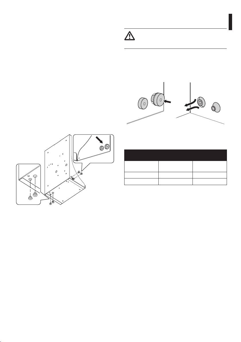
5.4.1 Drilling the box (optional)
The product has 2 holes with seal rings for passing
through the power cord of the solenoid valve and
the delivery pipe. In order to assemble additional seal
rings, it is possible to create other holes on the base
and left-hand side.
Fig. 7
Limits of the cable port hole and the used cables
diameters.
LIMITATIONS OF USE RELATING TO THE DIAMETER OF
THE HOLE AND OF THE CABLES
Sealing ring Ø Cable port hole
Cable Ø limits
(mm/in)
(mm/in)
M16 16.5 5-9
M20 20.5 8-12
Tab. 1
Fig. 6
5
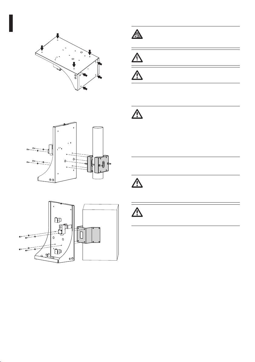
5.4.3 Assembly on supports
6 Assembling and installing
There are holes in the box for wall or oor mounting.
Never exceed performance specications.
Make all connections in a non-explosive
atmosphere.
Before starting any operation, make sure
the power supply is disconnected.
The assembly and installation must be
performed only by skilled personnel.
6.1 Installation
EN - English - Instructions manual
Fig. 8
6.1.1 Installing the pump tank
The box can be also mounted on the pole mount
If using the pump at temperatures below
adapter or the corner adaptor .
3°C (37.4°F) add some antifreeze liquid
to the water. The liquid used must have
an ignition temperature (IEC 60079-4) at
least 50K above the maximum surface
temperature of the equipment. The
liquid used must not cause ignition of the
atmosphere.
6.1.2 Connection of the power supply
line
When commencing installation make sure
that the specications for the power supply
Fig. 9 WASEX+NXCOL.
for the installation correspond with those
required by the device.
Make sure that the power source and
connecting cables are suitable for the
power consumption of the system.
6.1.2.1 Connection of the solenoid valve
Connect the solenoid valve. For further information,
refer to the product use and installation manual.
Fig. 10 WASEX+NXCW.
6
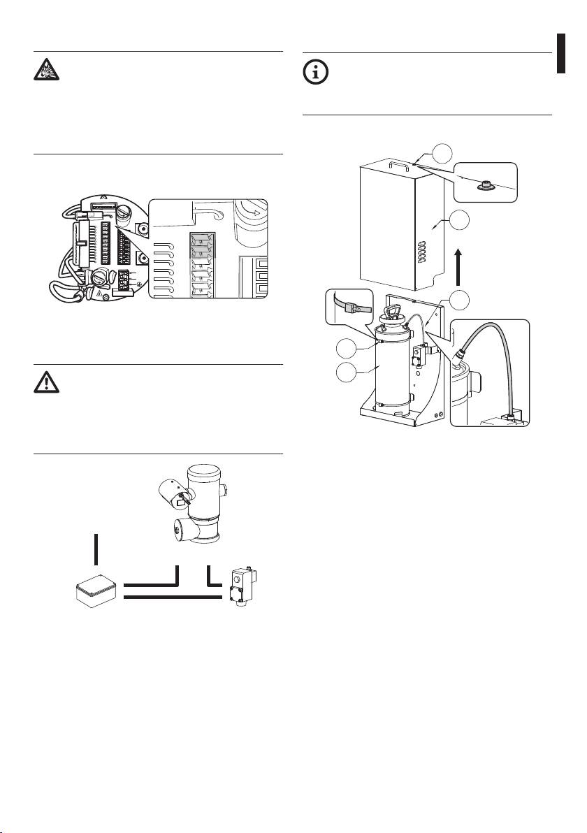
6.1.2.2 Connection to the pan & tilt
6.1.3 Installation of the pump
The electric connections between the
It is possible to install or service the pump
Instructions manual - English - EN
solenoid valve and P&T must be housed
without removing the tank. To remove the
in an explosion-proof junction box.
tank (01), release the metal clamps (02) and
The explosion-proof junction box must
disconnect the connecting pipe (03).
be suitable for the classication of the
Undo the safety screw (04) and lift the guard (05).
explosive atmosphere in the installation
site, according to the regulations in force.
04
Use the RL2 (J3) internal relay to connect to the pan &
tilt, if necessary.
ADDRESS & PROTOCOL
J4
F
U
S
E
J8
J3
FUS2
VIDEO - 1
J2
05
RL2
RL2
J9
J3
RL1
A
J6
FUS2
J8
RL1
B
COM
J2
AL5
A
RS485
AL4
B
VIDEO - 2
RL2
AL3
GND
AL2
W
J7
RL2
AL1
GND
FUS1
VAR1
AC
IN
J1
RL1
F
U
S
E
L
N
RL1
VAR2
VAR3
100nMBW3
COM
03
Fig. 11
Connect and power the solenoid valve with reference
02
to the connection diagram. (Fig. 12, page7).
The RL2 relay in the pan & tilt can withstand
01
a voltage of up to 30Vac. Use only 24Vac
models of solenoid valve powered by safety
transformer Turn o one of the supply
poles of the solenoid valve via the RL2 relay
of the pan & tilt.
Fig. 13
Safety transformer 24Vac
power supply
RL2 RL2
Solenoid valveExplosion-proof junction
box
Fig. 12
7
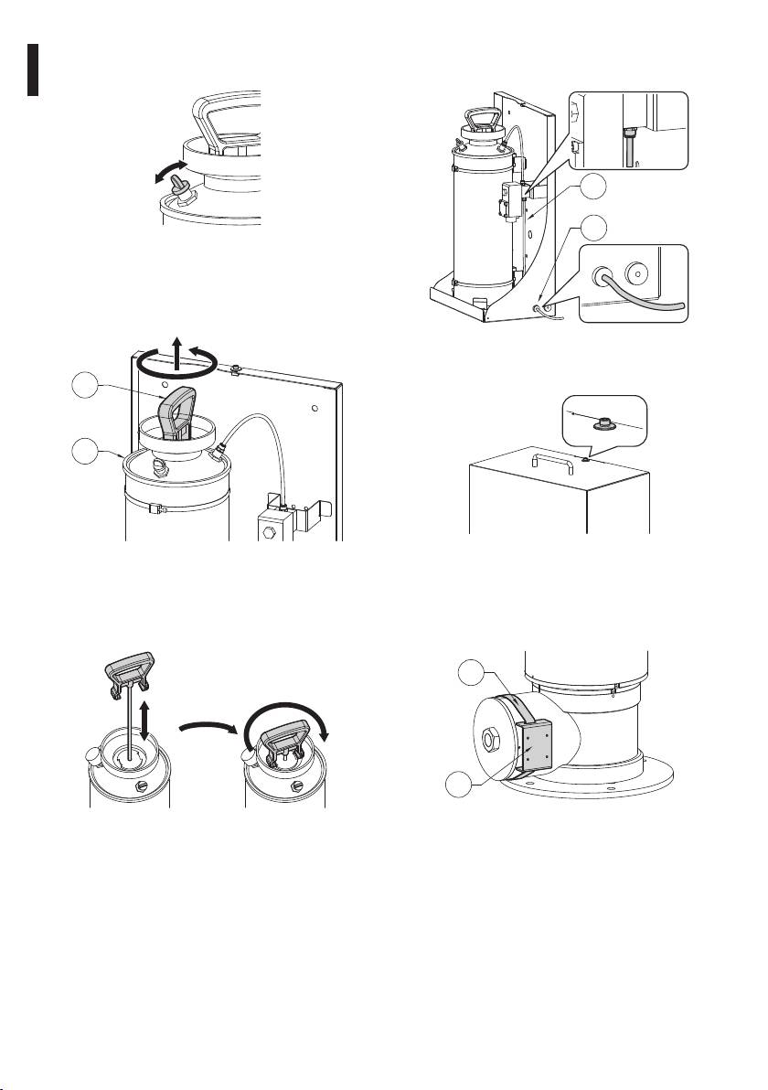
Turn the safety valve to release any residual pressure
Connect the delivery pipe (01), passing it through the
in the tank.
seal ring (02).
01
02
Fig. 14
Undo the top body of the pump (01) by turning it
EN - English - Instructions manual
anti-clockwise and removing it. Fill the tank (02) (10l
max) Re-install the top body of the pump.
Fig. 17
Insert the guard and tighten the safety screw.
01
02
Fig. 18
Fig. 15
6.1.4 Washer installation (pan & tilt)
Pressurize the tank by pumping the top body of the
pump up to a pressure of 3.5Bar. Turn the handle on
Fasten the bracket (01) onto the body of the pan & tilt
the body of the pump to its safety position.
with the metal clamp (02) provided.
02
01
Fig. 19
Fig. 16
8
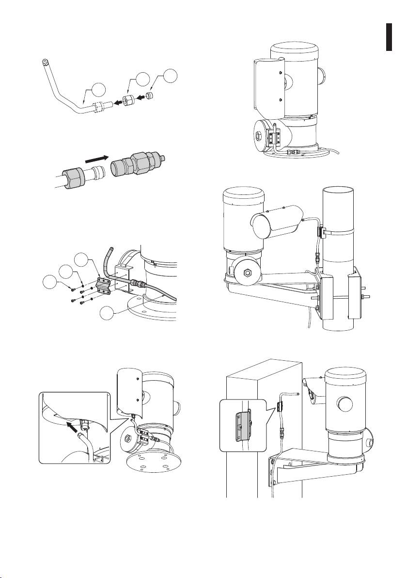
Shorten the washer pipe (01) as needed. Unscrew the
6.1.4.1 Installation examples
nut (02) and slide it along the pipe. Insert the end of
the pipe into the ogive (03).
Instructions manual - English - EN
03
02
01
Fig. 20
Lock the nut to the coupling.
Fig. 24
Fig. 21
Attach the pipe to the washer support using the
bracket (01), the screws (02) and the washers (03)
supplied. Connect the supply pipe (04).
01
03
02
04
Fig. 22
Fig. 25
To calibrate the jet direct the nozzle towards the glass
of the housing.
Fig. 23
To start the washer, refer to the pan & tilt manual.
Fig. 26 Pipe attached to the wall with a plate.
9
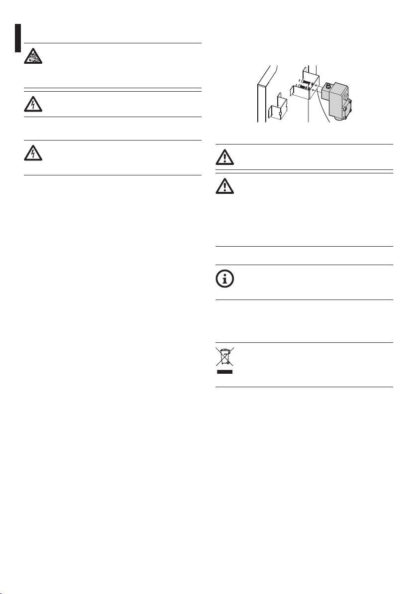
7.1.2 Extraordinary (to be done only
7 Maintaining and cleaning
under particular circumstances)
Before doing any technical work or
Replacing the solenoid valve
maintenance on the device, make sure that
potentially explosive atmosphere is not
present.
Before doing any technical work on the
device, disconnect the power supply.
7.1 Maintaining
Fig. 27
Maintenance must be carried out by
Whenever replacing the parts as indicated,
EN - English - Instructions manual
personnel trained to operate on electrical
always use VIDEOTEC original.
circuits.
The manufacturer declines all liability for
7.1.1 Routine (to be carried out
damage to any of the apparatus mentioned
regularly)
in this handbook, when resulting from
7.1.1.1 Filling the tank
tampering, use of non-original spare parts,
and from installation and maintenance/
Fill the tank with reference to the pump installation
repairs performed by non-authorised, non-
procedure (6.1.3 Installation of the pump, page7).
skilled personnel.
7.1.1.2 Cleaning the device
7.1.3 Spare parts
This should be done regularly. If a layer of dust
accumulates on the outside of the housing, it should
To order the spare parts it is necessary to
never be more than 5mm thick. The device should be
provide the serial number of the product on
cleaned using a damp cloth; compressed air must not
which the intervention is to be carried out.
be used. Maintenance frequency will depend on the
type of environment in which the housing is used.
8 Disposal of waste
7.1.1.3 Inspecting the cables
The cables should not show signs of damage or wear,
materials
which could generate hazardous situations. In this
case extraordinary maintenance is necessary.
This symbol mark and recycle system
are applied only to EU countries and not
applied to the countries in the other area of
the world.
Your product is designed and manufactured with
high quality materials and components which can be
recycled and reused.
This symbol means that electrical and electronic
equipment, at their end-of-life, should be disposed of
separately from your household waste.
Please dispose of this equipment at your local
Community waste collection or Recycling centre.
In the European Union there are separate collection
systems for used electrical and electronic products.
10

9 Technical data
Instructions manual - English - EN
9.1 General
Enclosure in stainless steel AISI 316L
Passivated and electropolished external surfaces
Reservoir capacity: 10l (2.6gal)
Pipe material: Antistatic plastic
9.2 Mechanical
Pressure: 4bar
Delivery head: 20m (66ft)
Dimensions (WxHxL): 429x697x255mm (16.9x27.4x10in)
Unit weight: 18kg (40lb)
9.3 Electrical
Power supply: 24Vac/dc, 50/60Hz
Consumption: 20W max
9.4 Environment
Indoor/Outdoor
Operating temperature: -40 to +60°C (-40°F to 140°F)
IP66 (referring exclusively to the electrovalve)
9.5 Certications
Solenoid valve:
ATEX (EN 60079-0: 2009, EN 60079-1: 2007, EN 60079-31: 2009)
-
b
II 2 GD Exd IIC T4 Gb
Ex tb IIIC T130°C Db
GOST-R
- 1 Exd IIC T4
9.6 Cable glands
1/2" NPT CABLE GLAND SELECTION LAYOUT
Zone, Gas Cable gland
Certication Operating
Cable Cable glands
Diameter of
type
temperature
part code
the external
cable (mm)
IIC, Zone 1 or
Barrier IECEX/ATEX/
-60 / +100°C
Not armored OCTEXB1/2C 3 - 8
Zone 2
GOST
(-76°F / +212°F)
IIB or IIA, Zone 1
IIB or IIA, Zone 2 With gasket IECEX/ATEX/
-60 / +100°C
Not armored OCTEX1/2C 3 - 8
GOST
(-76°F / +212°F)
Not armored OCTEXS1/2C 7.5 - 11.9
Tab. 2
11
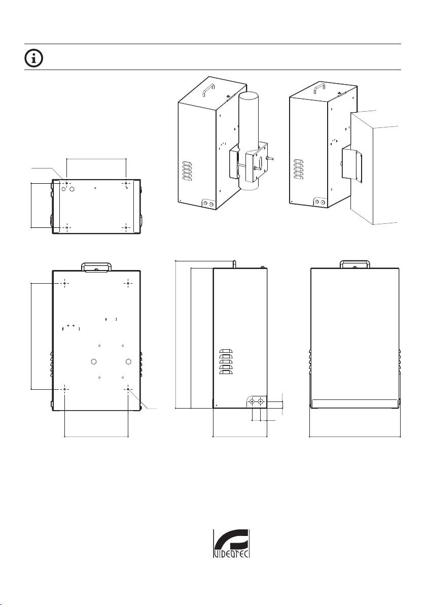
10 Technical drawings
The dimensions of the drawings are in millimetres.
280
WASEX+NXCOL WASEX+NXCW
MNVKWASEX_1245_EN
210
697
662
40
30
255300
429
500
Ø 11
32
Ø 11
Fig. 28 WASEX.
Headquarters Italy Videotec S.p.A.
Via Friuli, 6 - I-36015 - Schio (VI) Italy
Tel. +39 0445 697411 - Fax +39 0445 697414
Email: info@videotec.com
www.videotec.com
