Videotec EXPT: инструкция
Раздел: Видеотехника
Тип:
Инструкция к Videotec EXPT
EXPTC
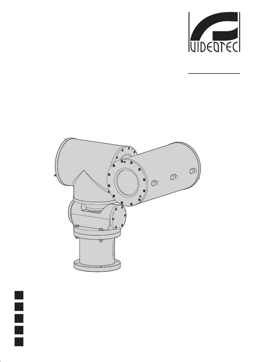
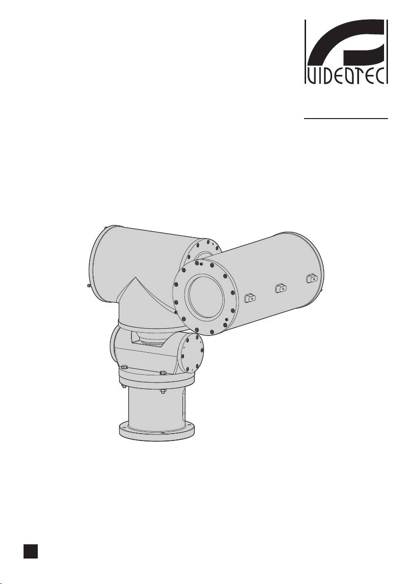
Explosion proof Pan&Tilt with integrated camera housing
EN
English - Instructions manual
IT
Italiano - Manuale di istruzioni
FR
Français - Manuel d'instructions
DE
Deutsch - Bedienungslanleitung
RU
Русский - Учебник инструкции

EXPTC
Explosion proof Pan&Tilt with integrated camera housing
EN
English - Instructions manual
ENGLISH


Contents
ENGLISH
EN - English - Instructions manual
1 About this manual ........................................................................................................ 5
1.1 Typographical conventions ................................................................................................................................ 5
2 Notes on copyright and information on trademarks ................................................ 5
3 Safety rules ................................................................................................................... 5
4 Identification ................................................................................................................ 6
4.1 Product description and type designation ................................................................................................... 6
4.1.1 Version for thermal imaging cameras ............................................................................................................................. 7
4.1.2 Version with glass protection device .............................................................................................................................. 7
4.2 Product markings ................................................................................................................................................... 8
5 Preparing the product for use ..................................................................................... 9
5.1 Safety precautions before use ........................................................................................................................... 9
5.2 Contents and unpacking ..................................................................................................................................... 9
6 Installing and assembling ............................................................................................ 9
6.1 Assembly ................................................................................................................................................................... 9
6.1.1 Range of use............................................................................................................................................................................. 9
6.1.2 Specification of maximum values when installing cameras, including lens .................................................... 9
6.2 Installation ..............................................................................................................................................................10
6.2.1 Installing the camera ..........................................................................................................................................................10
6.2.2 Installing the pan & tilt ....................................................................................................................................................... 10
6.2.3 Connecting the pan & tilt .................................................................................................................................................. 10
6.2.4 Adjusting the limit switches (Autopan version) ........................................................................................................ 11
6.2.5 How use the P&T ..................................................................................................................................................................11
6.2.6 Changing the back cover gasket ....................................................................................................................................11
7 Instructions for safe operation ..................................................................................12
7.1 Safe operation .......................................................................................................................................................12
7.1.1 Commissioning .....................................................................................................................................................................12
7.1.2 Safety rules .............................................................................................................................................................................12
7.1.3 Explosion prevention rules ...............................................................................................................................................12
8 Maintaining and cleaning .......................................................................................... 12
8.1 Maintenance and cleaning by users .............................................................................................................. 12
8.1.1 Routine (to be carried out regularly) .............................................................................................................................12
8.1.2 Extraordinary (to be done only under particular circumstances): ......................................................................13
8.2 Parts ...........................................................................................................................................................................13
8.3 Repairs ..................................................................................................................................................................... 13
9 Disposal of waste materials .......................................................................................13
10 Technical data ........................................................................................................... 14
10.1 General ..................................................................................................................................................................14
10.2 Mechanical ...........................................................................................................................................................14
10.3 Electrical ................................................................................................................................................................ 14
10.4 Accessories ...........................................................................................................................................................14
10.5 Related products ................................................................................................................................................ 14
3

10.6 Environment ........................................................................................................................................................14
10.7 Compliance to ..................................................................................................................................................... 15
10.8 Spare parts list .....................................................................................................................................................15
10.9 Package .................................................................................................................................................................15
11 Technical drawings ...................................................................................................15
12 Appendix A - Marking codes ................................................................................... 17
12.1 ATEX Mark ............................................................................................................................................................. 17
12.2 IECEx Mark ............................................................................................................................................................ 17
12.3 GOST-R Mark ........................................................................................................................................................ 18
12.4 Gas group classification ................................................................................................................................... 18
EN - English - Instructions manual
13 Appendix B - Electrical diagram .............................................................................. 19
14 Appendix C - Connecting EXDTRX3-EXDTRX324 receiver ....................................20
15 Appendix D - EXPT Declaration ............................................................................... 21
4
1 About this manual
3 Safety rules
Before installing and using this unit, please read this
The manufacturer declines all responsibility
EN - English - Instructions manual
manual carefully. Be sure to keep it handy for later
h
for any damage caused by an improper use
reference.
of the appliances mentioned in this manual.
Furthermore, the manufacturer reserves
1.1 Typographical conventions
the right to modify its contents without any
prior notice. The documentation contained
DANGER!
in this manual has been collected with great
g
High level hazard.
care, the manufacturer, however, cannot
Risk of electric shock; disconnect the
take any liability for its use. The same thing
power supply before proceeding with any
can be said for any person or company
operation, unless indicated otherwise.
involved in the creation and production of
this manual.
DANGER!
o
Explosion hazard.
This device must be connected to an earth
Read carefully to avoid danger of explosion.
h
conductor.
WARNING!
h
Medium level hazard.
This operation is very important for the
system to function properly: please read
the procedure described very carefully and
carry it out as instructed.
INFO
j
Description of system specifications.
We recommend reading this part carefully
in order to understand the subsequent
stages.
2 Notes on copyright and
information on trademarks
The quoted names of products or companies are
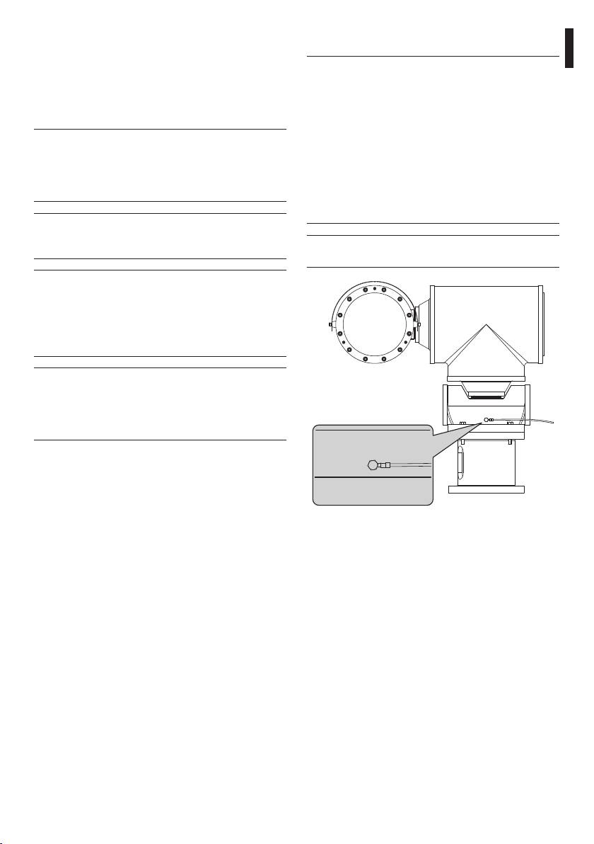
Fig. 01 Earth connection.
trademarks or registered trademarks.
• Make sure that all the devices are suitable for the
application and for the environment in which they
will be installed.
• Make sure that the connected devices are
completely compatible and suitable for use.
• Make sure the operating temperatures are
compatible with the devices.
• When installing the devices take care to be sure
the system and installer personnel are absolutely
safe.
5

• This device is remotely controlled and may change
• Before powering the device install an overload
position at any time. It should be installed so that
protection device in the electrical equipment for
no one can be hit by moving parts. It should be
the building.
installed so that moving parts cannot hit other
• The user must not install any apparatus inside the
objects and create hazardous situations.
device if it generates dangerous radiation.
• Choose an installation site that is strong enough
• For technical services, consult only and exclusively
to sustain the weight of the device, also bearing
authorised technicians.
in mind particular environmental aspects, such as
• Keep this handbook carefully; it must be available
exposure to strong winds.
for consultation on the installation site.
• We strongly recommend using only approved
• Never, under any circumstances, make any
brackets and accessories during installation.
changes or connections that are not shown in this
• Make sure that the device is firmly anchored so
handbook: improper use of the device can cause
EN - English - Instructions manual
that it cannot become detached.
serious hazards, risking the safety of personnel and
• Since the user is responsible for choosing the
of the system.
surface to which the device is to be anchored,
• Use only VIDEOTEC original spare parts.
we do not supply screws for attaching the device
• Before proceeding with installation check the
firmly to the particular surface. The installer is
supplied material to make sure it corresponds
responsible for choosing screws suitable for the
to the order specification by examining the
specific purpose on hand.
identification labels ("4.2 Product markings", page 8).
• The device must be installed and maintained only
and exclusively by qualified technical personnel.
4 Identification
• Use appropriate tools for the purpose. The
particular nature of the site where the device is to
4.1 Product description and type
be installed may mean special tools are required
designation
for installation.
• Make sure that the installation complies with local
The EXPT series explosion-proof pan & tilt (P&T)
regulations and specifications.
devices have been designed to allow movement, on
both a horizontal and a vertical plane, of cameras
• This device must be installed out of the reach of
operating in industrial environments in which there
the user or of anyone who might happen to touch
may be an explosive atmosphere due to gas, vapours,
it by chance.
mists, or air or powder mixtures.
• Before doing any technical work on the device,
EXPT pan & tilt devices, supplied complete with
disconnect the power supply.
camera housing, are made of a solid, cast Anticorodal
• Do not use power supply cables that seem worn
aluminium alloy from the AlSi7Mg EN AB-42000
or old.
group, the exact chemical composition of which is
• Only qualified technical personnel should be
defined in the UNI EN 1706 standard.
allowed to open the device, and they should work
Depending on the model, all parts are powder-
in a non-explosive atmosphere. Tampering with
painted and oven-cured or treated with special
the device will invalidate the guarantee.
coatings giving excellent resistant to UV light, to salt
• Do not allow children or untrained people to use
spray and to atmospheric pollutants.
the device.
The P&T basically consists of a base, a central body
• The device can only be considered to be switched
and a third part designed as a housing for the
off when the power supply has been disconnected
camera. The base contains the connection for the
and the connection cables to other devices have
control cable (multipolar cabling with 29 conductors
been removed.
and 2 coaxial cables); the central body contains the
motors for horizontal and vertical movements; the
third component comprises the camera housing.
6

The central body contains the two potentiometers for
4.1.2 Version with glass protection
the preset option and the indispensable electronic
device
parts for automatic operation, plus the junctions for
The EXPT series of explosion-proof pan & tilt devices
EN - English - Instructions manual
connecting the input cable via an Ex d 3/4" NPT IP66
can be fitted with a glass protection device, installed
barrier armoured cable gland, complying with the
on the front opening of the housing. It comprises a
housing markings.
flange for linking with the housing, a closing flange
The central body contains the motors for horizontal
and a central, explosion-proof body containing a
and vertical movements. The EXPT series P&T use
strong, transparent glass, a 24Vdc motor, two winders
single phase, synchronous AC motors; the motors
and transparent Mylar film, installed in front of the
transmit horizontal and vertical motion via a
glass.
wheel-pinion and link chain, with rotation in both
The motor uses 4 bevel gears to pilot a winder for
directions plus immediate stop and reverse. Inside
recovering dirty film, while the other winder issues
the movement mechanism there is a worm screw /
clean film. The motor is remotely controlled by a two-
crown wheel system to ensure complete absence of
wire ON-OFF contact (one common and one +24Vac/
mechanical play during operation.
Vdc, Fig. 13, page 19).
The housing body also comprises a cylindrical,
aluminium tube, closed by a flange that houses a
The control unit for the glass protection
strong, transparent glass; on the opposite side there
h
device is supplied by the customer.
is another flange that, as well as closing the cylinder,
supports the plate to which the camera is to be
The transparent Mylar film can be fed forward about
attached.
350 times.
The P&T has an IP66 protection degree.
When the film is dirty the operator starts the motor,
so that the film is fed forward until a clean image is
4.1.1 Version for thermal imaging
obtained (to completely replace the dirty film in one
cameras
step, about 50mm of clean film should be fed).
When using thermal imaging cameras, which are able
The end of the tape is marked by printing on the last
to detect heat emission, a special filter on the front
50cm of film.
of the housing should be used. This housing differs
Film feed can also be started automatically by a
in that it has a window made mainly of germanium,
timing device if a suitable control system is used (this
which guarantees the same strength and security
is not supplied).
properties as those for standard glass. Range of
To change the film, see the Videotec spare part
application from 7.5 to 14µm.
handbook (code OEXMYLAR).
7
07. Camera:
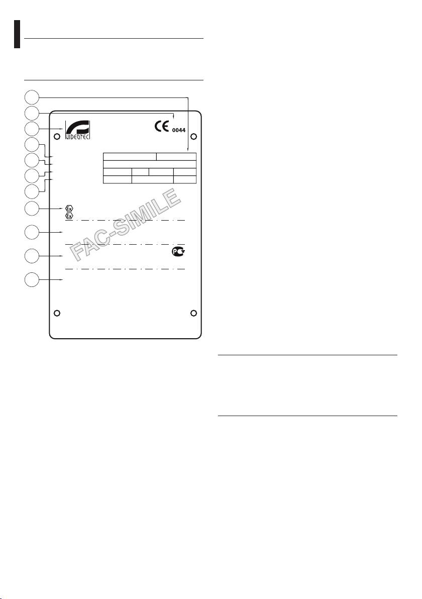
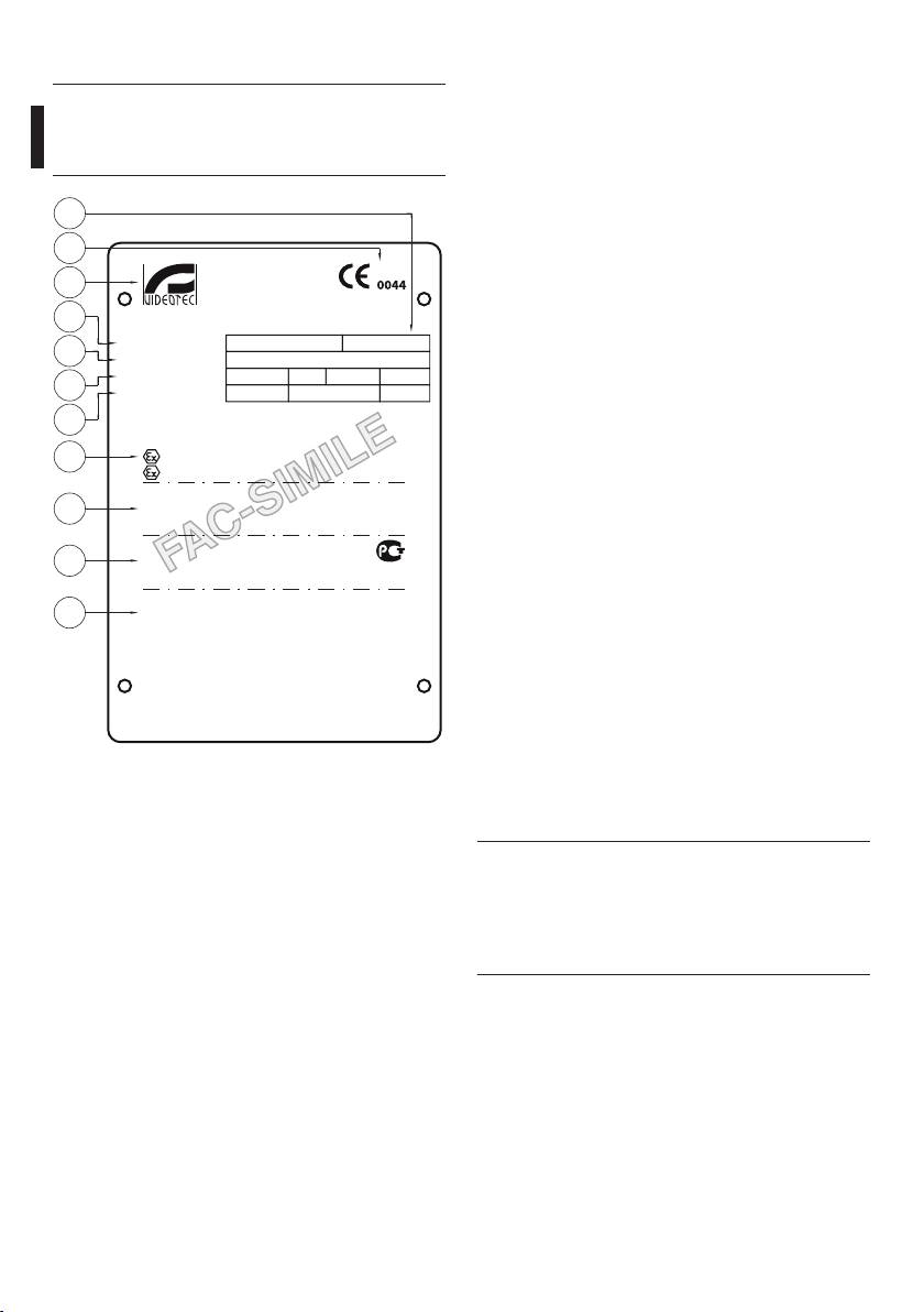
4.2 Product markings
• Power supply voltage (V)
The versions with the germanium window
• Maximum power consumption (W) - (the data
h
are ATEX- and GOST- certified. (Check
for the camera refer to the voltage specification
the certifications on the data plate of the
and maximum allowed power consumption for
product you have purchased).
camera operation)
08. ATEX certification:
04
• ATEX certificate number
01
• Classification for zone type, protection method,
VIDEOTEC S.p.A.
Via Friuli, 6
temperature class for which this product may be
02
36015 Schio (VI)
0044
ITALY
used in compliance with the ATEX directive
www.videotec.com
03
EN - English - Instructions manual
• CE mark and number of notified body that
Model/Модель:
T
amb.
-20/+50 °C
carries out production checks
05
Serial N°/Сер. №:
Pan & Tilt/Поворотное
09. IECEx certification:
устройство:
V
A
Hz
W
max
06
Camera/Камера:
V
W
max
• IECEx certificate number
07
• Classification for zone type, protection method
TÜV 04 ATEX 2585
and temperature class for which this product
08
ee 2G Ex d eeC T6 Gb
may be used in compliance with the IECEx
ee 2D Ex t eeeC T85˚C Db IP66
standard
IECEx TUN 05.0016
09
Ex d eeC T6 Gb
10. GOST-R certification:
Ex t eeeC T85˚C Db IP66
РОСС IT.ГБ05.В04259
• GOST-R certificate number
10
1 Ex d eeC T6 Gb
ГБ05
• Classification for zone type, protection method
Ex tb eeeC T85˚C Db IP66
and temperature class for which this product
CNEx 10.3142
11
Ex d eeC T6 Gb
may be used in compliance with the GOST-R
DIP A21 TA T6
STANDARD
WARNING - DO NOT OPEN WHEN ENERGIZED
11. Chinese certification:
ПРЕДУПРЕЖДЕНИЕ - НЕ ОТКРЫВАТЬ ПРИ ПОДКЛЮЧЕННОМ ПИТАНИИ
CAUTION - USE FASTENERS WITH YIELD STRESS ≥ 700 N/mm^2
ОСТОРОЖНО – СЛЕДУЕТ ИСПОЛЬЗОВАТЬ ВИНТЫ С ПРЕДЕЛОМ ТЕКУЧЕСТИ ≥ 700 N/mm^2
• CNEx certificate number
USE STAINLESS STEEL SCREWS, TYPE A2 UNI 5931, DIN 912
ИСПОЛЬЗОВАТЬ ВИНТЫ ИЗ НЕРЖАВЕЮЩЕЙ СТАЛИ, ТИП A2 UNI 5931, DIN 912
MADE IN ITALY
• Classification of the type of area, the protection
method and the temperature range the product
can be used in according to Chinese standards
Fig. 02 Example of data plate.
Before installation, make sure the power
01. CE symbol
h
supply and protection specifications of the
02. Manufacturer’s name and address
device correspond to those in the original
03. Model identification code
order. Use of unsuitable appliances can
cause serious hazards, risking the safety of
04. Ambient temperature of use referring to
personnel and of the installation.
model identification code
05. Serial number
06. Pan & tilt:
• Power supply voltage (V)
• Absorption current (A)
• Frequency (Hz)
• Housing power consumption (W)
8

5 Preparing the product
6 Installing and
for use
assembling
EN - English - Instructions manual
Any change that is not expressly approved
Only specialised personnel should be
h
by the manufacturer will invalidate both
h
allowed to install and assemble the device.
the guarantee and certification.
6.1 Assembly
5.1 Safety precautions before
6.1.1 Range of use
use
The EXPT pan & tilt is designed for use in a fixed
location, for surveillance of areas with class 1-21 or
The following procedures should be carried
class 2-22 potentially explosive atmospheres, using a
g
out with the power supply disconnected,
camera/lens installed inside the device by the user.
unless indicated otherwise. An appropriate
protection device should be installed in
The EXPT pan & tilt has been built and certified
the electrical equipment upstream of the
in compliance with ATEX directive 94/9/EC, with
device.
the international IECEx standard, with the GOST-R
STANDARDS and Chinese standards, which define
Never exceed performance specifications.
its range of application and minimum safety
o
Do not replace the housing screws with
requirements.
other kinds of screw. Make all connections
The P&T for thermal imaging cameras have been
in a non-explosive atmosphere.
built and certified in compliance with ATEX directive
94/9/CE and with the GOST-R STANDARD, which
The device must be installed only
define the range of application and minimum safety
h
and exclusively by qualified technical
requirements.
personnel. Make connections and tests
6.1.2 Specification of maximum values
in the laboratory before carrying out
when installing cameras, including lens
installation on site. Use appropriate tools
for the purpose.
The installer should never use devices
h
that do not remain within the specified
5.2 Contents and unpacking
maximum values.
When the product is delivered, make sure that the
• Maximum power - 20W
package is intact and that there are no signs that it
• Maximum voltage - 24Vac
has been dropped or scratched.
• Usable volume for camera/lens: 2800cm
If there are obvious signs of damage, contact the
supplier immediately.
• Minimum distance between the walls of the
housing and the camera/lens: 12mm
Keep the packaging in case you need to send the
product for repairs.
Check the contents to make sure they correspond
with the list of materials as below:
• 1 explosion-proof pan & tilt device
• 1 gasket kit
• 1 user’s handbook
9
6.2 Installation
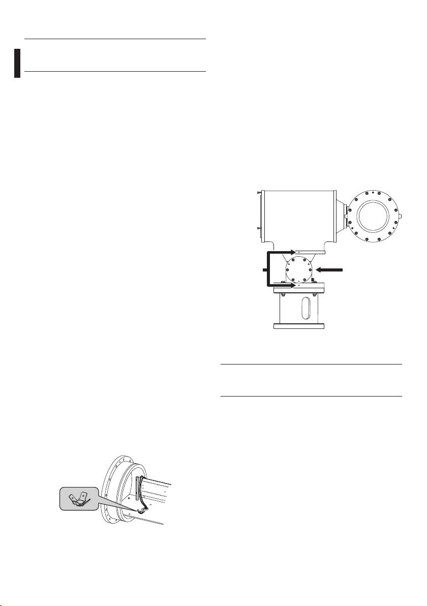
6.2.2 Installing the pan & tilt
For a wall-mounted P&T, the special bracket is used:
The installer must not use devices that
this is attached using the 4 holes, diameter 11mm.
h
generate dangerous radiation.
For a parapet mounting, on the other hand, it is
possible to make use of the supporting disc on the
One of the most important features of the EXPT
base, which has 4 holes, 8.5mm diameter, at 90°
series P&T is the complete absence of rotation cables,
intervals.
whether for controlling the P&T or for controlling the
As regards this, to make sure the P&T is able to move
camera. This means that installation and maintenance
through its whole range, the bottom flange of the
of the P&T are simple.
central body and the support disc on the base have
The multipolar cable supplied is already connected
two red vertically aligned marks.
and leaves the base via the Ex d 3/4" NPT IP66
When the P&T has been installed, these marks should
armoured barrier cable gland.
EN - English - Instructions manual
face the installer, because they represent the point
The two flanges on the housing and the three flanges
of reference for horizontal movement over the whole
on the central body each have 12 screws, while the
range of ±180° with respect to the installation point.
two flanges on the base each have 6 screws. All the
screws have a hexagonal head and a M6 thread. In
addition, each flange has 3 screws at 120° intervals to
facilitate extraction of the flange itself. When the M6-
thread screws have been unscrewed from the flange,
turning the 3 screws at 120° intervals (one turn per
screw at a time, in turn) will make it easier to extract
the flange.
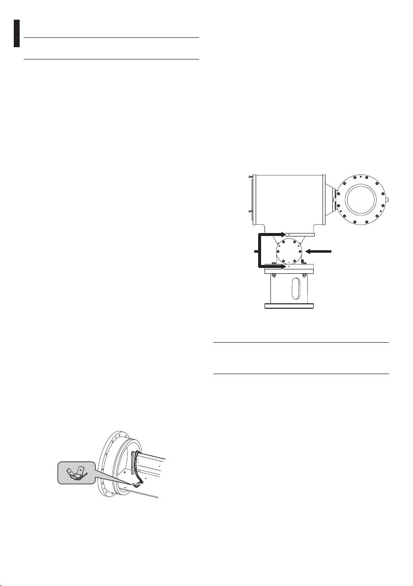
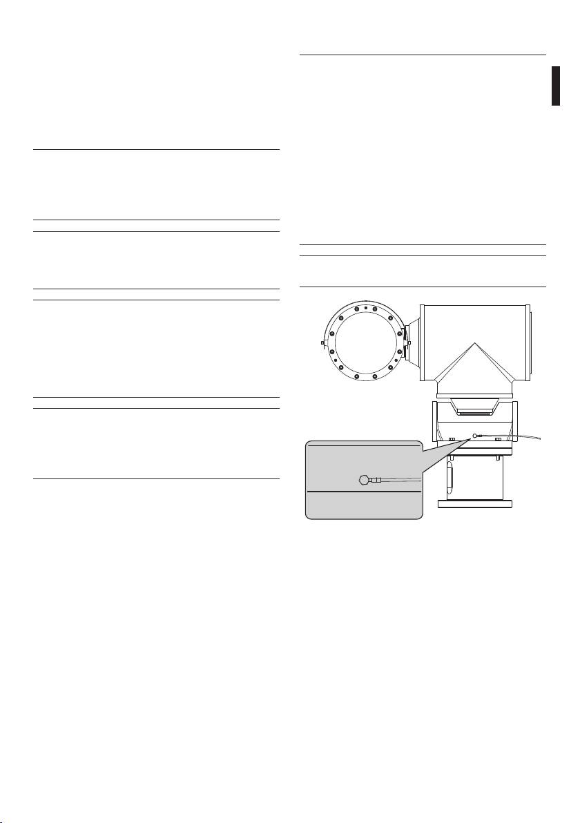
6.2.1 Installing the camera
Marks
Flange
(other side)
To install the camera, you have to extract the flange
closing the housing, which also supports the plate to
which the camera will be attached, and the related
terminal board. This plate is supported on two guides
attached to the housing; when the flange is removed,
the plate slides along the guides, so that it is easy to
Fig. 04
fit and connect the camera and its accessories. During
installation, we strongly recommend insulating the
6.2.3 Connecting the pan & tilt
camera from the support plate using the supplied
insulating spacers.
Before proceeding with the following
h
operations, make sure that the P&T control
Before closing the flange, after installing the
unit voltage is correct.
camera, make sure that the 4 earth wires have been
connected (back cover, front cover, housing body,
To connect the pan & tilt to the control unit, use the
terminal board) and make sure they have been
supplied multipolar cable. Refer to the electrical
placed at the same potential.
diagram attached to this handbook and carry out the
We recommend a torque wrench setting of 12.5Nm
following operations:
for the 12 screws closing the flange.
• Disconnect the control unit from the power supply;
• Make the connections with the P&T (motors,
camera, lens etc.);
• Power the unit;
• Carry out the operational tests.
Fig. 03
10
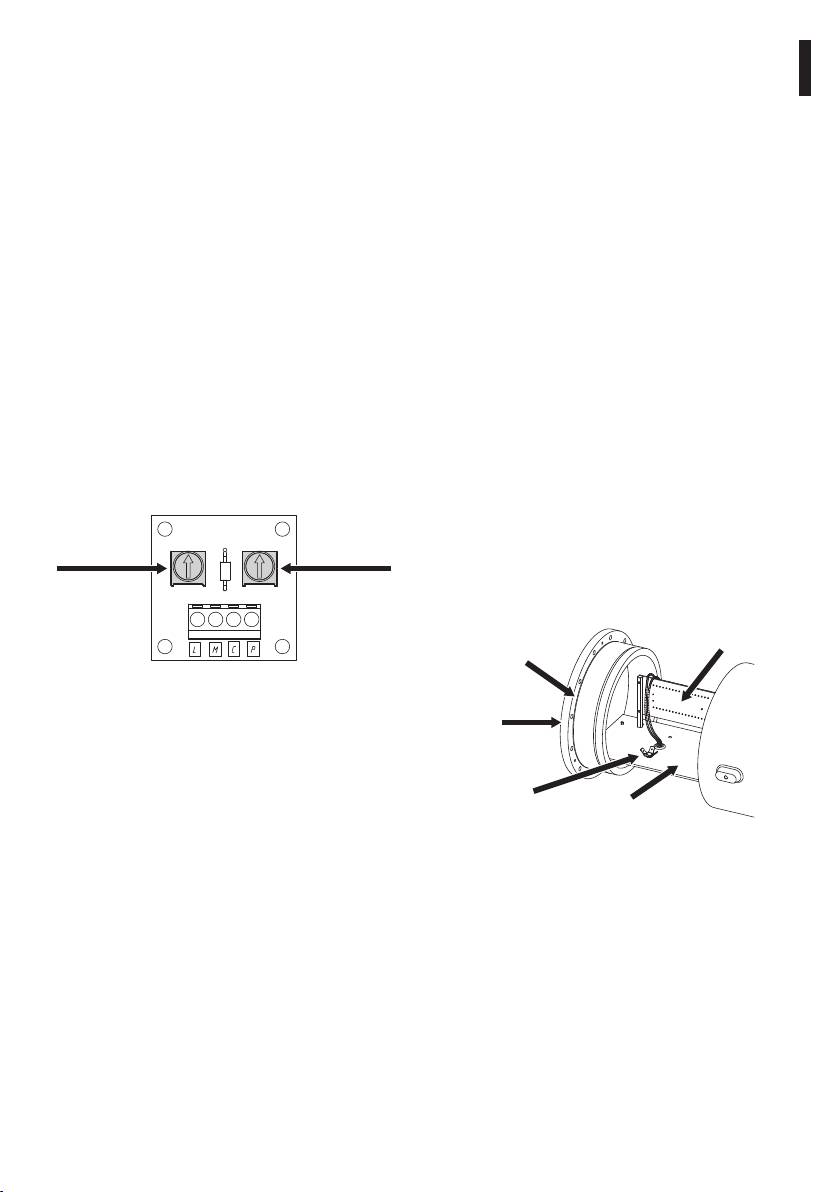
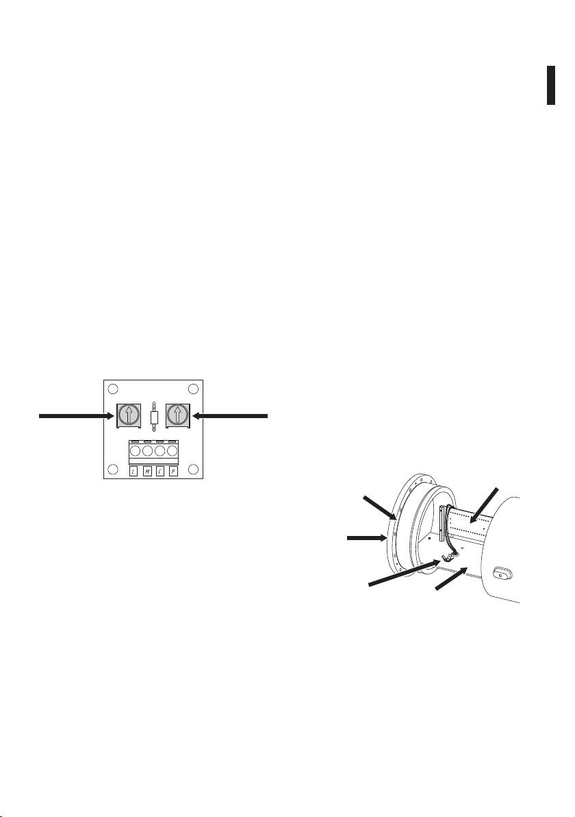
6.2.4 Adjusting the limit switches
6.2.5 How use the P&T
(Autopan version)
Remote control of the pan & tilt can be achieved in
the following ways:
To adjust the potentiometers for the electronic limit
EN - English - Instructions manual
switches controlling automatic cyclical panning,
• Manual - By directly piloting the motors via a
take out the base flange that is opposite to the
control console, with immediate start, stop and
flange with the red mark. The PCB containing the
reverse on both a horizontal plane (max 360°) and
two potentiometers, RV1 and RV2, is attached to
a vertical plane (max -90°/+90°); there are two
this flange.Take out the flange and keep it facing the
mechanical limit stops at the ends of the maximum
installer. The RV1 potentiometer (horizontal angle)
allowed rotation range, to prevent further rotation
will be on the right, and is used to regulate the size
if the electronic limit switches (microswitches) do
of the required angle during automatic horizontal
not work.
rotation. Potentiometer RV2, on the left (autopan
• Autopan - Only for rotation on a horizontal plane,
position) is used to position the angle fixed with
over a cyclical range in both directions, for a
potentiometer RV1, in the required area over the
maximum angle of 270°. The limits are set by the
whole 360° range, by turning the knob clockwise or
two potentiometers (RV1 and RV2) situated on the
anti-clockwise until the desired position is reached.
PCB inside the base (autopan option).
As regards potentiometer RV1, when it is turned anti-
• Automatic to preset points - Using the two
clockwise as far as it will go, the minimum angle will
potentiometers (P1 and P2) situated on the axes of
be obtained (30°), while turning it clockwise as far as
rotation and mechanically connected to horizontal
it will go will obtain the maximum angle (270°).
and vertical movements; with this operating mode
Intermediate values can be obtained by turning the
it is possible to store the angular position of the P
knob partially in either direction until the desired
&T using special external control circuits (preset
angle is reached.
option).
RV2
RV1
6.2.6 Changing the back cover gasket
Autopan
Pan
If the back cover gasket of the housing is worn it
position
angle
should be replaced using the supplied spare or,
failing that, using only and exclusively a VIDEOTEC
original part.
Back cover
Terminal board
gasket
Fig. 05 Trimmer diagram.
To reach the connections (made by soldered joins)
Flange
of the multipolar input cable, it is necessary to
extract the base flange corresponding to the mark.
Two wires spiral out from the joins, one of which
terminates on the PCB terminal board situated in
Earth
connection
the central body, while the other terminates on the
Fixing plate
camera control terminal board inside the housing.
Fig. 06
Since the input cable is already connected when the
device is supplied (as explained earlier), access to
When changing the gasket, take care to make sure it
these connections is unnecessary during installation
is properly inserted in its seating.
of the P&T, but access has been made possible for
Reconnect the earth wires that had been
maintenance purposes.
disconnected in order to extract the flange.
Close the flange properly, using a torque wrench
setting of 12.5Nm when tightening the 12 screws.
11

Always remember that the unit must
7 Instructions for safe
o
be connected to an appropriate earth
conductor.
operation
7.1 Safe operation
After commissioning the system keep this
h
handbook in a safe place, available for later
Before proceeding with the following
consultation.
g
operations, make sure that the mains
voltage is correct.
8 Maintaining and cleaning
7.1.1 Commissioning
Before doing any technical work on the
• Read the whole of this user’s handbook very
h
device, disconnect the power supply.
EN - English - Instructions manual
carefully;
• Install the camera and lens correctly;
8.1 Maintenance and cleaning
• Test system operation for positive results;
by users
• Prepare an appropriate power supply line;
8.1.1 Routine (to be carried out
• Connect the control unit correctly to the P&T.
regularly)
7.1.2 Safety rules
• Cleaning the glass - Water should be used, or a
• Given the considerable weight of the system, use
liquid detergent that will not generate a hazardous
an appropriate transport and handling system;
situation.
• Before starting any operation, make sure the
• Cleaning the germanium window - Use neutral
power supply is disconnected;
soap diluted with water; take extra care not to
• Before powering the system, install an overload
scratch or damage the outer surface treated with
protection device in the electrical equipment for
carbon coating. Damage to this coating could
the building;
interfere with the transparency of the surface to
infrared light. Do not use ethyl alcohol, solvents,
• Make sure that all precautions for personal safety
hydrogenated hydrocarbons, strong acids or
have been taken;
alkalis. Using these products will irreparably
• Installation of the electrical equipment must
damage the germanium surface.
comply with the local legislation in force.
• Cleaning the device - This should be done
7.1.3 Explosion prevention rules
regularly; if a layer of dust accumulates on the
• Choose a solid, stable support surface;
outside of the housing, it should never be more
than 5mm thick. The device should be cleaned
• Choose an appropriate support bracket, if used;
using a damp cloth; compressed air must not be
• Use appropriate tools for the area in which you are
used. Maintenance frequency will depend on the
working;
type of environment in which the pan & tilt is used.
• Do not open the housing if there is a possibility of
your being in a potentially explosive atmosphere;
• Use safe, long-lasting screws or other anchorage
systems.
12

• Inspecting the cables - The cables should not
The manufacturer declines all liability for
show signs of damage or wear, which could
h
damage to any of the apparatus mentioned
generate hazardous situations; in this case
in this handbook, when resulting from
EN - English - Instructions manual
extraordinary maintenance is necessary.
tampering, use of non-original spare parts,
and from installation and maintenance/
• Changing the Mylar tape (version with glass
repairs performed by non-authorised, non-
protection device) - This should be done in the
skilled personnel.
presence of the minimum safety conditions as
indicated in the instructions for safe operation. To
carry out the operation, unscrew the four screws
In all such circumstances, the housing
fastening the glass protection cover in order to
j
should be sent to the workshop for the
replace the set of reels holding the dirty tape by
necessary repairs or maintenance.
those with the clean tape, by simply sliding them
out.
8.2 Parts
• Opening the housing to change the camera -
Check the condition of the back cover gasket; if it
It is necessary to provide the series number
needs changing use only the one supplied with the
j
of the product requiring assistance, so that
housing or, failing that, use only VIDEOTEC original
parts may be ordered (ex@videotec.com).
spare parts (see the instructions for Changing the
back cover gasket.
8.3 Repairs
8.1.2 Extraordinary (to be done only
For any other maintenance operation
under particular circumstances):
j
the housing must be sent to VIDEOTEC,
• Changing the front unit with glass (or the glass
upon request for authorisation to return it
protection unit when present);
(techsupport@videotec.com).
• Changing the inner slide unit with heater wiring
and electrical connection board, using the
9 Disposal of waste
appropriate spare part for versions with or without
the glass protection device;
materials
• Hazardous wear or damage to cables;
This symbol mark and recycle system
• Pan & tilt failure;
are applied only to EU countries and not
• Camera or lens failure;
n
applied to the countries in the other area of
• Explosion in or near the P&T;
the world.
• Any other situation in which the P&T or control
Your product is designed and manufactured with
unit has to be opened.
high quality materials and components which can be
For damage to any parts that are not
recycled and reused.
h
indicated above, repair or replacement
This symbol means that electrical and electronic
must be done by VIDEOTEC.
equipment, at their end-of-life, should be disposed of
separately from your household waste.
Whenever replacing the parts as indicated,
Please dispose of this equipment at your local
h
always use VIDEOTEC original spare parts
Community waste collection or Recycling centre.
and meticulously follow the maintenance
In the European Union there are separate collection
instructions supplied with every spare parts
systems for used electrical and electronic products.
kit.
13

10 Technical data
10.3 Electrical
Power supply IN 24Vac, 50/60Hz
10.1 General
Horizontal and vertical motor consumption: 50W max
Non-corrosive die-cast aluminium (anticorodal)
Standard vertical and horizontal preset potentiometers
Bicomponent polyurethane enamel with orange peel
Heater Ton 10°C +/-4°C Toff 25°C +/-3°C
effect, RAL7032
IN 24Vac, consumption 20W max
Special painting, blue colour RAL7001. Resistant to stress
Reinforced heater Ton 10°C +/-4°C Toff 25°C +/-3°C
cracking, adverse weather conditions, detergents, salt-
spray and typical airborne pollutants
3 resistors in the housing
2 resistors in the P&T (one for each motor)
10.2 Mechanical
Consumption 100W max
0-360° horizontal movement
Glass protection device
EN - English - Instructions manual
Horizontal speed: 6°/s
24Vac/Vdc, consumption 2W max
Horizontal Torque: 2.5kgm
Devices to install inside the housing
+/-90° vertical movement
Camera equipped with lens with maximum total power:
20W
Vertical speed: 2.4°/s
Maximum voltage: 24Vac
Vertical torque: 6kgm
Available volume for camera/lens: 2800cm
Horizontal limit switch adjustable only for the Autopan
function
Minimum distance between the walls of the housing and
the camera/lens: 12mm
1 cable gland Ex d 3/4" NPT IP66 for armoured cables in
the base of the P&T according the housing marking
10.4 Accessories
One multiconductors armoured cable normally supplied
7.5m (24ft) length, diameter 20.8mm (0.8in): 25 poles
EXPTS000 Sunshield 650mm (25.6in)
0.5mm, 4 poles 1mm, 2 RG175, 75 Ohm
for EXPTC
External dimensions
EXPTS001 Sunshield 760mm (29.9in)
EXPTC 427.5x571.4x560mm
for EXPTD
(16.8x322.5x22in)
10.5 Related products
EXPTD 573.5x581x580mm
(22.6x22.9x22.8in)
EXPTWB000 Bracket for EXPT RAL7032
Internal dimensions
EXPTWB00R Bracket for EXPT RAL7001
EXPTC Ø 180x380mm (7x14.9in)
EXDTRX3 Telemetry receiver 17
EXPTD Ø 180x460mm (7x18.1in)
functions, 230Vac
Internal usable area
EXDTRX324 Telemetry receiver 17
functions, 24Vac
EXPTC 100x100x280mm
(3.9x3.9x11in)
10.6 Environment
EXPTD 100x100x280mm
(3.9x3.9x11in)
Operating temperature with heater: -20°C / +50°C
Window
Operating temperature with reinforced heater:
-40°C / +50°C
EXPTC Ø 114mm (4.5in)
Always refer to the temperature in the marking
EXPTD 70x56mm (2.7x2.2in)
Glass protection device
Glass protection device: Ø 250x140mm (9.8x5.5in)
Mylar film 80mm (3.1in) wide and 18m (59ft) length, 350
shifting steps, marks printed on the last 50cm (19in)
Wall Bracket
Load rating: 100kg (220lb)
Length: 676mm (26.6in)
14
10.9 Package
Unit Weight:
EN - English - Instructions manual
EXPTC 56.5kg / 124.5lb
EXPTD 62kg / 136.9lb
EXPTWB 11kg / 24.2lb
Package Weight:
EXPTC 61.2kg / 134.9lb
EXPTD 66kg / 145.5lb
EXPTWB 11kg / 24.3lb
Package Dimensions (BxHxL):
EXPTC 76x 41x67cm /
29.9x16.1x26.4in
EXPTD 76x 41x67cm /
29.9x16.1x26.4in
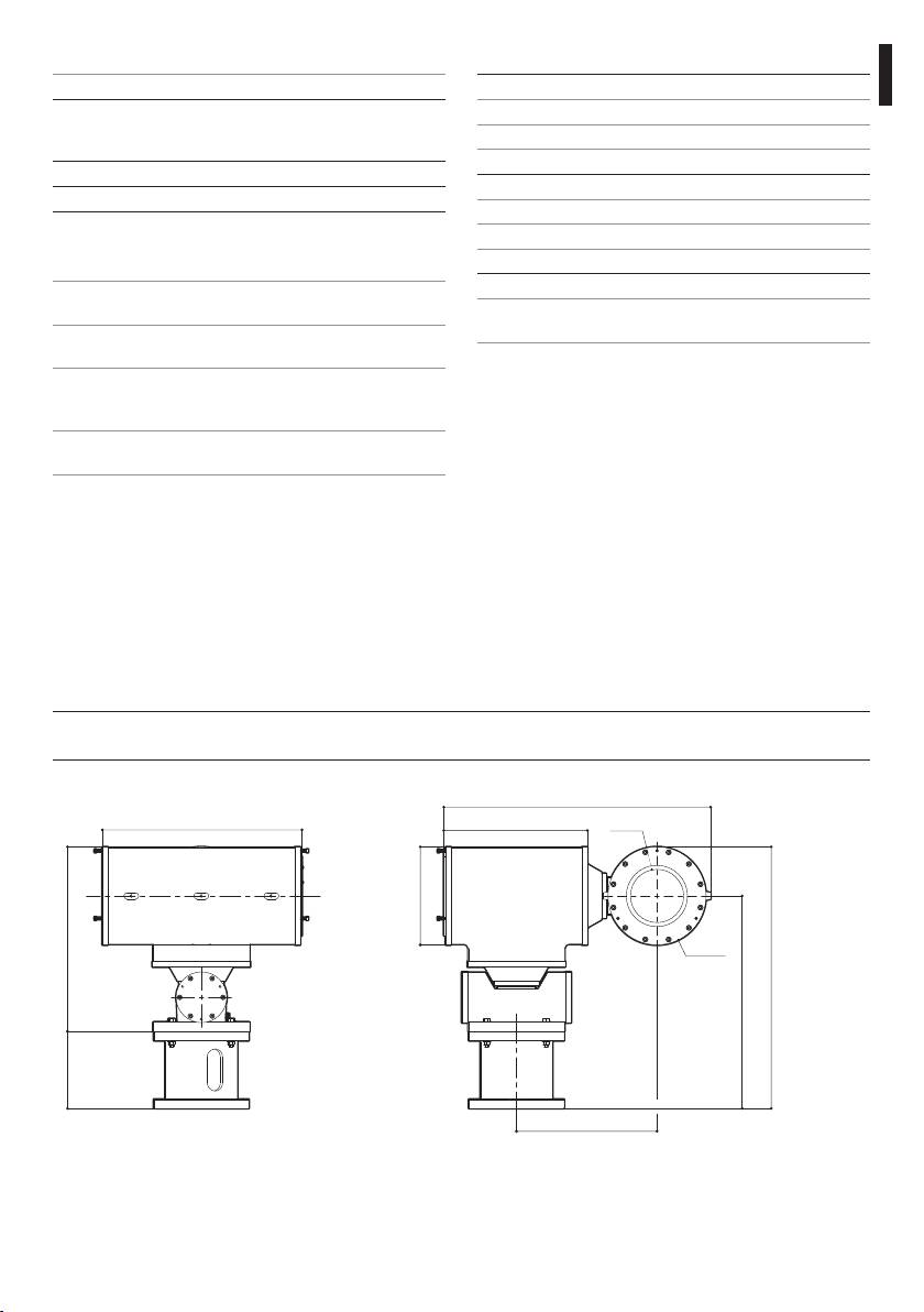
11 Technical drawings
The values are in millimeters.
j
428
308
Ø 210
15
571
Ø 114
Ø 210
560
455
301
395
165
10.7 Compliance to
For each version, verify the existing certification:
IECEx (TUV Nord Certification), protocols IEC 60079-
0:2007 Edition 5.0, IEC 60079-1:2007 Edition 6.0, IEC
60079-0:2008 Edition 1.0
ATEX (TUV Nord Certification), directive 94/9/CE
GOST-R (NANIO CCVE Certification)
Chinese certification (CNEx certification)
10.8 Spare parts list
OEXMYLAR Mylar film replacement kit,
18m (59ft) 350 steps
OEXVET Front flange complete with
glass for EXPTC RAL7032
OEXDPV Front flange complete with
glass protection device for
EXPTD RAL7032
OSLIEX Internal slide complete with
heater for EXPTC
OSLIEXD Internal slide complete with
heater for EXPTD
Fig. 07 EXPTC
574
EN - English - Instructions manual
16
581
308 70
56
580
455
415165
Ø 210
Ø 250
301
676
23
220
180
270
Fig. 08 EXPTD
20
8
230
Ø 11
Ø 206
Ø 8.5
Ø 180
Ø 60
573
Fig. 09 EXPTWB
12 Appendix A - Marking codes
12.1 ATEX Mark
EN - English - Instructions manual
ee
2G Ex d eeC T6 Gb
ee
2D Ex t eeeC T85°C Db IP66
Fig. 10
Group (surface
Category (high
Gas Explosion-proof
Gas group Gas temperature
Protection level of the
device, no
protection
housing for potentially
classification
equipment for gas
mining)
degree, the
explosive environments
device in this
category can be
installed in zones
1 and 2)
Group (surface
Category (high
Dust Dust ignition protection
Dust group Maximum surface
Protection level of the
IP protection degree
device, no
protection
for zone types 21-22
temperature for dusts
equipment for dust
mining)
degree, the
device in this
category can be
installed in zones
21 and 22)
Tab. 01
12.2 IECEx Mark
Ex d eeC T6 Gb
Ex t eeeC T85°C Db IP66
Fig. 11
Explosion-proof
Gas group Gas temperature
Protection level of the
housing for
classification
equipment for gas
potentially explosive
environments
Dust ignition
Dust group Maximum surface
Protection level of the
IP protection degree
protection for zone
temperature for dusts
equipment for dust
types 21-22
Tab. 02
17
12.3 GOST-R Mark
1 Ex d eeC T6 Gb
Ex tb eeeC T85˚C Db IP66
Fig. 12
Protection level Explosion-proof
Gas group Gas temperature
Protection level of the
housing for
classification
equipment for gas
potentially explosive
EN - English - Instructions manual
environments
Dust ignition
Dust group Maximum surface
Protection level of the
IP protection degree
protection for zone
temperature for dusts
equipment for dust
types 21-22
Tab. 03
12.4 Gas group classification
The table below shows the classification of some gases and vapours, according to the explosion-proof
protection group and the temperature class. For a complete list see IEC/EN 60079-12 and IEC/EN 60079-20.
T1 T2 T3 T4 T5 T6
IIA Acetone N-Butane Petrol Acetaldehyde Ethyl nitrate
Ethanol N-Butyl Diesel fuel Ether
Ethyl acetate Avgas
Ammonia Heating oil
Pure benzene N-Hexane
Acetic acid
Carbon monoxide
Methanol
Propane
Toluene
IIB Ethylene
IIC Hydrogen Acetylene Carbon
disulphide
Tab. 04 The above temperature classes automatically cover the lower classes (T6 is better than T1).
Class IIB also covers class IIA. Class IIC also covers classes IIB and IIA.
TEMPERATURE CLASS T1 T2 T3 T4 T5 T6
Maximum allowed surface temperature (°C) for the
450 300 200 135 100 85
housing* in the corresponding class
Tab. 05 * Normally refers to the maximum ambient temperature of the installation. The lower the ignition temperature of the related
explosive atmosphere, the higher should be the maximum allowed surface temperature of the housing.
The maximum surface temperature is determined for a 5mm-thick layer of powder and the installation
regulations require a margin of 75K between the surface temperature and the ignition temperature of the
powder under consideration.
18
13 Appendix B - Electrical diagram
EN - English - Instructions manual
Fig. 13
19

14 Appendix C - Connecting EXDTRX3-EXDTRX324
receiver
TERMINAL BLOCK
TERMINAL BLOCK GROUP
WIRE EXPT WIRE MARKING EXPT
EXDTRX3EXDTRX324
EXDTRX3EXDTRX324
FOCUS FAR S3 FOCUS + LENSES
FOCUS NEAR S4 FOCUS - LENSES
ZOOM TELE S5 ZOOM + LENSES
ZOOM WIDE S6 ZOOM - LENSES
POT SUPPLY + S7 VCC PRESET
POT SUPPLY - S8 GND PRESET
EN - English - Instructions manual
FOCUS ERROR S9 FOCUS PRESET
ZOOM ERROR S10 ZOOM PRESET
GLASS DEVICE S13 LINE WASHER
GLASS DEVICE S14 AC WASHER
EARTH S15 EARTH WASHER
COMMON S16 COM PAN/TILT
LEFT S17 LEFT PAN/TILT
RIGHT S18 RIGHT PAN/TILT
AUTOPAN S19 AUTO PAN/TILT
DOWN S20 DOWN PAN/TILT
UP S21 UP PAN/TILT
HORIZ. ERROR S22 PAN PRESET
VERT. ERROR S23 TILT PRESET
POT SUPPLY + S24 VCC PRESET
POT SUPPLY - S25 GND PRESET
Tab. 06
20

15 Appendix D - EXPT Declaration
EN - English - Instructions manual
21

VIDEOTEC S.p.A.
www.videotec.com
Printed in Italy
MNVCEXPT_1307_EN
EXPT
Brandeggio antideflagrante con custodia integrata
IT
Italiano - Manuale di istruzioni
ITALIANO


Sommario
ITALIANO
1 Informazioni sul presente manuale ............................................................................ 5
1.1 Convenzioni tipografiche .................................................................................................................................... 5
IT - Italiano - Manuale di istruzioni
2 Note sul copyright e informazioni sui marchi commerciali ...................................... 5
3 Norme di sicurezza ....................................................................................................... 5
4 Identificazione .............................................................................................................. 6
4.1 Descrizione e designazione del prodotto ..................................................................................................... 6
4.1.1 Versione per telecamere termiche ................................................................................................................................... 7
4.1.2 Versione con dispositivo protezione vetro ................................................................................................................... 7
4.2 Marcatura del prodotto ........................................................................................................................................ 8
5 Preparazione del prodotto per l'utilizzo .................................................................... 9
5.1 Precauzioni di sicurezza prima dell'utilizzo................................................................................................... 9
5.2 Contenuto e disimballaggio ............................................................................................................................... 9
6 Installazione e assemblaggio ...................................................................................... 9
6.1 Assemblaggio .......................................................................................................................................................... 9
6.1.1 Campo di utilizzo .................................................................................................................................................................... 9
6.1.2 Specifiche massime delle telecamere comprese di ottica installabili ................................................................. 9
6.2 Installazione ...........................................................................................................................................................10
6.2.1 Installazione della telecamera ......................................................................................................................................... 10
6.2.2 Installazione del brandeggio ...........................................................................................................................................10
6.2.3 Collegamento del brandeggio ........................................................................................................................................10
6.2.4 Regolazione fine corsa (versione con Autopan) .......................................................................................................11
6.2.5 Modi di utilizzo ......................................................................................................................................................................11
6.2.6 Sostituzione guarnizione fondo posteriore ................................................................................................................ 11
7 Istruzioni di funzionamento in sicurezza .................................................................12
7.1 Funzionamento in condizioni di sicurezza .................................................................................................. 12
7.1.1 Messa in servizio ................................................................................................................................................................... 12
7.1.2 Prescrizioni di sicurezza .....................................................................................................................................................12
7.1.3 Prescrizioni di prevenzione di esplosione ................................................................................................................... 12
8 Manutenzione e pulizia.............................................................................................. 12
8.1 Manutenzione e pulizia da parte degli utilizzatori ...................................................................................12
8.1.1 Ordinaria (da eseguire periodicamente) ......................................................................................................................12
8.1.2 Straordinaria (da eseguire solo in casi particolari): ..................................................................................................13
8.2 Ricambi ....................................................................................................................................................................13
8.3 Riparazioni ..............................................................................................................................................................13
9 Smaltimento dei rifiuti ...............................................................................................13
10 Dati tecnici ................................................................................................................14
10.1 Generale ................................................................................................................................................................ 14
10.2 Meccanica ............................................................................................................................................................. 14
10.3 Elettrico .................................................................................................................................................................14
10.4 Accessori ...............................................................................................................................................................14
10.5 Prodotti correlati ................................................................................................................................................14
3

10.6 Ambiente ..............................................................................................................................................................14
10.7 Conformità ...........................................................................................................................................................15
10.8 Lista ricambi .........................................................................................................................................................15
10.9 Imballaggio .......................................................................................................................................................... 15
11 Disegni tecnici .......................................................................................................... 15
12 Appendice A - Codifica della marcatura .................................................................17
12.1 Marcatura ATEX ...................................................................................................................................................17
12.2 Marcatura IECEx .................................................................................................................................................. 17
12.3 Marcatura GOST-R ..............................................................................................................................................18
12.4 Classificazione gruppi gas ..............................................................................................................................18
13 Appendice B - Schema elettrico ..............................................................................19
14 Appendice C - Collegamento al ricevitore EXDTRX3-EXDTRX324 ........................20
IT - Italiano - Manuale di istruzioni
15 Appendice D - Dichiarazione EXPT .........................................................................21
4
1 Informazioni sul presente
3 Norme di sicurezza
manuale
Il produttore declina ogni responsabilità
h
per eventuali danni derivanti da un
Prima di installare e utilizzare questa unità, leggere
uso improprio delle apparecchiature
attentamente questo manuale. Conservare questo
menzionate in questo manuale. Si
IT - Italiano - Manuale di istruzioni
manuale a portata di mano come riferimento futuro.
riserva inoltre il diritto di modificarne il
contenuto senza preavviso. Ogni cura é
1.1 Convenzioni tipografiche
stata posta nella raccolta e nella verifica
PERICOLO!
della documentazione contenuta in questo
g
Pericolosità elevata.
manuale, tuttavia il produttore non può
Rischio di scosse elettriche. Togliere
assumersi alcuna responsabilità derivante
l'alimentazione prima di procedere con le
dall'utilizzo della stessa. Lo stesso dicasi
operazioni, salvo diversa indicazione.
per ogni persona o società coinvolta nella
creazione e nella produzione di questo
manuale.
PERICOLO!
o
Pericolo di esplosione.
Leggere attentamente per evitare pericoli
Questo dispositivo deve essere collegato a
di esplosione.
h
terra.
ATTENZIONE!
h
Pericolosità media.
L'operazione è molto importante per il
corretto funzionamento del sistema. Si
prega di leggere attentamente la procedura
indicata e di eseguirla secondo le modalità
previste.
INFO
j
Descrizione delle caratteristiche del
sistema.
Si consiglia di leggere attentamente per
comprendere le fasi successive.
2 Note sul copyright e
informazioni sui marchi
Fig. 01 Messa a terra.
commerciali
• Assicurarsi che tutti i dispositivi siano adatti per
l’applicazione e l’ambiente per cui sono stati
I nomi di prodotto o di aziende citati sono marchi
progettati.
commerciali o marchi commerciali registrati
appartenenti alle rispettive società.
• Assicurarsi che i dispositivi collegati siano
completamente compatibili e adatti all’uso.
• Controllare che le temperature di esercizio siano
compatibili con i dispositivi.
• Accertarsi di installare i dispositivi in maniera
tale da garantire la sicurezza dell’impianto e del
personale addetto all’installazione.
5

• Questa apparecchiatura è soggetta a controllo
• Prima dell’alimentazione del dispositivo installare
remoto e può spostarsi in qualsiasi momento. Deve
un dispositivo di protezione nell’impianto elettrico
essere installata in modo che le parti in movimento
dell’edificio.
non abbiano da colpire nessuna persona. Deve
• Si raccomanda all’utente di non installare
essere installata in modo che le parti in movimento
all’interno del dispositivo qualsiasi apparecchiatura
non abbiano da colpire altri oggetti da creare
che generi radiazioni pericolose.
situazioni di pericolo.
• Per l’assistenza tecnica rivolgersi esclusivamente al
• Scegliere la postazione di installazione in modo
personale tecnico autorizzato.
che sia sufficientemente solida da sostenere il
• Conservare con cura il presente manuale; deve
peso del dispositivo, considerando anche aspetti
essere a disposizione per eventuali consultazioni
ambientali particolari come esposizione a vento
nel luogo in cui viene eseguita l’installazione.
forte.
• Non effettuare per nessun motivo alterazioni o
• Si raccomanda di utilizzare solo staffe o accessori
collegamenti non previsti in questo manuale:
consigliate per l’installazione.
l’uso di apparecchi non idonei può portare a
• Accertarsi che il dispositivo sia fissato in maniera
gravi pericoli per la sicurezza del personale e
IT - Italiano - Manuale di istruzioni
solida ed affidabile.
dell’impianto.
• Dato che la scelta della superficie di montaggio
• Utilizzare solo parti di ricambio VIDEOTEC.
è a cura dell’utente non si forniscono viti per il
• Prima di procedere con l'installazione controllare
fissaggio sicuro del dispositivo alla superficie. È
che il materiale fornito corrisponda alle specifiche
responsabilità dell’installatore utilizzare viti adatte
richieste esaminando le etichette di marcatura ("4.2
allo scopo specifico richiesto.
Marcatura del prodotto", pagina 8).
• L’installazione e la manutenzione del dispositivo
deve essere eseguita solo da personale tecnico
4 Identificazione
qualificato.
• Utilizzare degli utensili adeguati. Degli utensili
4.1 Descrizione e designazione
specifici possono essere richiesti, per motivi
del prodotto
di installazione, in relazione al luogo in cui il
dispositivo viene installato.
I brandeggi antideflagranti della serie EXPT sono
• Assicurarsi che l’installazione soddisfi le specifiche
stati progettati per consentire lo spostamento,
locali.
sia sul piano orizzontale che su quello verticale,
di telecamere o altre apparecchiature operanti in
• Questo dispositivo deve essere installato fuori dalla
ambienti industriali in cui vi è la probabilità che si
portata dell’utente o di chiunque ne possa entrare
manifestino atmosfere esplosive dovute a gas, vapori,
a contatto casualmente.
nebbie o miscele di aria o polveri.
• Prima di effettuare interventi tecnici
I brandeggi EXPT, forniti completi di custodia per
sull’apparecchio togliere l’alimentazione elettrica.
telecamera, sono realizzati in massiccia fusione in
• Non utilizzare cavi di alimentazione con segni di
lega di alluminio Anticorodal del gruppo AlSi7Mg EN
usura o invecchiamento.
AB-42000 la cui composizione chimica è definita dalla
• L’apparecchio deve essere aperto soltanto da
norma UNI EN 1706.
personale tecnico qualificato e in atmosfera non
Secondo il modello, tutti gli elementi sono verniciati
esplosiva. La manomissione dell’apparecchio fa
con polveri in forno o trattati con particolari
decadere i termini di garanzia.
rivestimenti che offrono un’eccellente resistenza ai
• Non permettere l’uso dell’apparecchio a bambini
raggi ultravioletti, alla nebbia salina e agli agenti
o incapaci.
inquinanti presenti nell’atmosfera.
• L’apparecchio si considera disattivato soltanto
II brandeggio è essenzialmente costituito da un corpo
quando l’alimentazione é disinserita e i cavi di
di base, un corpo centrale e da un terzo corpo adibito
collegamento con altri dispositivi sono stati
a custodia per la telecamera. II corpo di base ospita il
rimossi.
collegamento del cavo dei comandi (cavo multipolare
cablato da 29 conduttori e due coassiali), il corpo
centrale ospita i motori per i movimenti orizzontale
e verticale, iI terzo corpo costituisce la custodia per
l’alloggiamento della telecamera.
6

II corpo centrale contiene i due potenziometri di
4.1.2 Versione con dispositivo
preset e le parti elettroniche indispensabili per il
protezione vetro
funzionamento in automatico e le giunzioni per
I brandeggi antideflagranti della serie EXPT possono
la connessione del cavo di ingresso attraverso un
essere equipaggiati con il dispositivo di protezione
pressacavo a barriera armato Ex d 3/4" NPT IP66,
vetro, installato sull’apertura frontale della custodia.
conforme alla marcatura della custodia.
Esso è costituito da una flangia di raccordo con
IT - Italiano - Manuale di istruzioni
II corpo centrale contiene i motori per il movimento
la custodia, una flangia di chiusura e da un corpo
orizzontale e quello verticale. I brandeggi della serie
centrale antideflagrante contenente un robusto
EXPT utilizzano motori sincroni in corrente alternata
vetro trasparente, un motore in corrente continua
monofase; i motori, tramite ruota-pignone e catena
alimentato a 24Vdc, due avvolgitori ed una pellicola
a maglie, trasmettono i movimenti orizzontale e
trasparente in Mylar, installata di fronte al vetro.
verticale che consentono la rotazione nei due sensi
Il motore, attraverso 4 pignoni conici dentati, pilota
con arresto e inversione immediati. All’interno
un avvolgitore per il recupero della pellicola sporca,
la meccanica del movimento è costituita da un
mentre l’altro avvolgitore rilascia la pellicola pulita.
sistema vite senza fine-corona dentata che assicura
Il motore è controllato remotamente tramite un
l’assoluta assenza di giochi meccanici durante il
contatto ON-OFF a due fili (un comune ed un +24Vac/
funzionamento.
Vdc, Fig. 13, pagina 19).
II corpo custodia è anch’esso costituito da un tubo
cilindrico di alluminio, chiuso da una flangia che
L’unità di controllo del dispositivo
alloggia un robusto vetro trasparente; dalla parte
h
protezione vetro è fornita dal cliente.
opposta è presente un’ulteriore flangia che, oltre a
chiudere il cilindro, supporta la piastra per il fissaggio
La pellicola di Mylar trasparente consente circa 350
della telecamera.
passi di avanzamento.
Il grado di protezione del brandeggio è IP66.
Infatti quando è sporca l’operatore attiverà il motore,
facendo avanzare la pellicola sino ad ottenere
4.1.1 Versione per telecamere termiche
un’immagine pulita (il passo per consentire lo
L’impiego di telecamere termiche, in grado di rilevare
scorrimento completo della pellicola sporca è di circa
l’emissione di calore, richiede l’utilizzo di uno speciale
50mm).
filtro sul frontale della custodia. Questa custodia si
La fine del nastro viene segnalata mediante
differenzia per la presenza di una finestra composta
contrassegni stampati sugli ultimi 50cm di pellicola.
in prevalenza da Germanio; esso garantisce le stesse
L’avanzamento della pellicola potrà avvenire anche
caratteristiche di resistenza e di sicurezza del vetro
automaticamente in maniera temporizzata tramite
standard. Campo di applicazione da 7.5 a 14µm.
un opportuno sistema di controllo (escluso dalla
fornitura).
Per sostituire la pellicola fare riferimento al manuale
d'uso del ricambio VIDEOTEC (codice OEXMYLAR).
7
07. Telecamera:
4.2 Marcatura del prodotto
• Tensione d’alimentazione (V)
Le versioni con la finestra al Germanio
• Consumo massimo (W) – (i dati riportati per la
h
sono certificate ATEX e GOST. (Verificare le
telecamera si riferiscono alle caratteristiche di
certificazioni nella targhetta del prodotto
tensione e consumo massimo ammesso per il
acquistato).
funzionamento della stessa)
08. Certificazione ATEX
04
• Numero del certificato ATEX
01
• Classificazione del tipo di zona, metodo di
VIDEOTEC S.p.A.
Via Friuli, 6
protezione, classe di temperatura per le quali è
02
36015 Schio (VI)
0044
ITALY
ammesso l’impiego di questo prodotto secondo
www.videotec.com
03
la direttiva ATEX
Model/Модель:
T
amb.
-20/+50 °C
• Marcatura CE e numero dell’organismo
05
Serial N°/Сер. №:
notificato che effettua il controllo sulla
Pan & Tilt/Поворотное
устройство:
V
A
Hz
W
max
IT - Italiano - Manuale di istruzioni
06
produzione
Camera/Камера:
V
W
max
09. Certificazione IECEx
07
TÜV 04 ATEX 2585
• Numero del certificato IECEx
08
ee 2G Ex d eeC T6 Gb
• Classificazione del tipo di zona, metodo di
ee 2D Ex t eeeC T85˚C Db IP66
protezione e classe di temperatura per le quali è
IECEx TUN 05.0016
09
Ex d eeC T6 Gb
ammesso l’impiego di questo prodotto secondo
Ex t eeeC T85˚C Db IP66
la normativa IECEx
РОСС IT.ГБ05.В04259
10
10. Certificazione GOST-R
1 Ex d eeC T6 Gb
ГБ05
Ex tb eeeC T85˚C Db IP66
• Numero del certificato GOST-R
CNEx 10.3142
11
Ex d eeC T6 Gb
• Classificazione del tipo di zona, metodo di
DIP A21 TA T6
protezione e classe di temperatura per le quali è
WARNING - DO NOT OPEN WHEN ENERGIZED
ammesso l’impiego di questo prodotto secondo
ПРЕДУПРЕЖДЕНИЕ - НЕ ОТКРЫВАТЬ ПРИ ПОДКЛЮЧЕННОМ ПИТАНИИ
CAUTION - USE FASTENERS WITH YIELD STRESS ≥ 700 N/mm^2
gli STANDARD GOST-R
ОСТОРОЖНО – СЛЕДУЕТ ИСПОЛЬЗОВАТЬ ВИНТЫ С ПРЕДЕЛОМ ТЕКУЧЕСТИ ≥ 700 N/mm^2
USE STAINLESS STEEL SCREWS, TYPE A2 UNI 5931, DIN 912
ИСПОЛЬЗОВАТЬ ВИНТЫ ИЗ НЕРЖАВЕЮЩЕЙ СТАЛИ, ТИП A2 UNI 5931, DIN 912
11. Certificazione cinese:
MADE IN ITALY
• Numero del certificato CNEx
• Classificazione del tipo di zona, metodo di
Fig. 02 Esempio di targa
protezione e classe di temperatura per le quali è
01. Simbolo CE
ammesso l’impiego di questo prodotto secondo
gli standard cinesi
02. Nome e indirizzo del costruttore
03. Codice di identificazione del modello
Prima dell’installazione controllare se
h
le caratteristiche di alimentazione e
04. Temperatura ambiente di utilizzo riferita al
protezione del dispositivo corrispondono
codice di identificazione del modello
a quelle richieste. L’uso di apparecchi non
05. Numero di serie
idonei può portare a gravi pericoli per la
06. Brandeggio:
sicurezza del personale e dell’impianto.
• Tensione d’alimentazione (V)
• Corrente assorbita (A)
• Frequenza (Hz)
• Consumo custodia (W)
8

5 Preparazione del
6 Installazione e
prodotto per l'utilizzo
assemblaggio
Qualsiasi cambiamento non espressamente
L'installazione e l'assemblaggio vanno
h
approvato dal costruttore fa decadere la
h
eseguiti solo da personale specializzato.
IT - Italiano - Manuale di istruzioni
garanzia e la certificazione.
6.1 Assemblaggio
5.1 Precauzioni di sicurezza
6.1.1 Campo di utilizzo
prima dell'utilizzo
L’impiego del brandeggio EXPT è definito per
l’utilizzo in postazione fissa per la sorveglianza
Le seguenti procedure sono da effettuare
di zone con atmosfera potenzialmente esplosiva
g
in assenza di alimentazione, se non
classificate 1-21 o 2-22, mediante telecamera/ottica
diversamente indicato. Un dispositivo
installata dall’utente al suo interno.
di protezione adeguato deve essere
installato nell’impianto elettrico prima del
Il brandeggio EXPT è costruito e certificato in
dispositivo.
accordo con la direttiva 94/9/CE ATEX, allo standard
internazionale IECEx, gli STANDARD GOST-R e gli
Non superare le prestazioni specificate. Non
standard cinesi, che ne definiscono il campo di
o
sostituire le viti della custodia con altre di
applicazione ed i requisiti minimi di sicurezza.
tipo diverso. Eseguire tutte le connessioni
Il brandeggio per telecamere termiche è costruito e
in atmosfera non esplosiva.
certificato in accordo con la direttiva 94/9/CE ATEX e
gli STANDARD GOST-R che ne definiscono il campo di
La fase di installazione deve essere
applicazione ed i requisiti minimi di sicurezza.
h
effettuata solo da personale tecnico
6.1.2 Specifiche massime delle
qualificato. Effettuare i collegamenti e
telecamere comprese di ottica
prove in laboratorio prima dell’installazione
nel sito. Utilizzare degli utensili adeguati.
installabili
Si raccomanda all’installatore di non
5.2 Contenuto e disimballaggio
h
utilizzare dispositivi che eccedano dalle
specifiche.
Alla consegna del prodotto verificare che l'imballo
sia integro e non abbia segni evidenti di cadute o
• Potenza massima: 20W
abrasioni.
• Tensione massima: 24Vac
In caso di evidenti segni di danno all'imballo
contattare immediatamente il fornitore.
• Volume utile per telecamera/ottica: 2800cm
Conservare l'imballo nel caso sia necessario inviare il
• Distanza minima tra le pareti della custodia e la
prodotto in riparazione.
telecamera/ottica: 12mm
Controllare che il contenuto sia rispondente alla lista
del materiale sotto indicata:
• 1 brandeggio antideflagrante
• 1 dotazione guarnizioni
• 1 manuale di istruzioni
9
6.2 Installazione
6.2.2 Installazione del brandeggio
Per installare il brandeggio a parete viene utilizzata
Si raccomanda all’installatore di non
l’apposita staffa, che si fissa tramite i 4 fori con
h
utilizzare dispositivi che generino
diametro 11mm, mentre per l’installazione su palo
radiazioni pericolose.
può essere sfruttato il disco di appoggio del corpo di
base, dotato di 4 fori da 8.5mm disposti a 90°.
Una delle caratteristiche principali dei brandeggi
A questo proposito, onde consentire una corretta
della serie EXPT é la totale assenza di cavi in
escursione del brandeggio, sulla flangia inferiore del
rotazione, sia per il comando del brandeggio che per
corpo centrale e sul disco di appoggio del corpo di
il controllo della telecamera. Tale soluzione facilita
base sono evidenziati due contrassegni rossi allineati
l’installazione e la manutenzione del brandeggio.
verticalmente.
Il cavo multipolare fornito a corredo è già collegato
Dopo avere installato il brandeggio, tali contrassegni
e fuoriesce dalla base tramite il pressacavo a barriera
dovranno essere rivolti verso l’installatore, in quanto
armato Ex d 3/4" NPT IP66.
rappresentano il punto di riferimento del movimento
Le due flange sulla custodia e le tre flange sul corpo
orizzontale per una corretta escursione di ±180°
IT - Italiano - Manuale di istruzioni
centrale sono dotate ciascuna di 12 viti, mentre le
rispetto al punto di installazione.
due flange sul corpo di base sono provviste ognuna
di 6 viti, tutte con cavità esagonale e filetto M6.
Inoltre, ciascuna flangia è dotata di 3 viti disposte
a 120° per facilitare l’estrazione della flangia stessa.
Infatti una volta svitate dalla flangia le viti con filetto
M6, avvitando le 3 viti a 120° (un giro alla volta, a
rotazione) si agevola l’estrazione della stessa.
6.2.1 Installazione della telecamera
Contrassegni
Flangia
Per installare la telecamera occorre estrarre la flangia
(opposta)
di chiusura della custodia, che supporta anche la
piastra di fissaggio della telecamera con la relativa
morsettiera. Questa piastra é appoggiata su due
guide fissate alla custodia; togliendo la flangia la
piastra scorre sulle guide, consentendo di montare
e collegare agevolmente la telecamera ed i suoi
Fig. 04
componenti accessori. In fase di installazione si
raccomanda di isolare la telecamera dalla piastra di
6.2.3 Collegamento del brandeggio
supporto utilizzando gli appositi distanziali isolanti
forniti a corredo.
Prima di effettuare le seguenti operazioni
h
assicurarsi che la tensione dell’unità di
Prima di chiudere la flangia, dopo l'installazione della
controllo del brandeggio sia corretta.
telecamera, verificare di aver collegato i 4 cavi di terra
(fondo posteriore, fondo anteriore, corpo custodia,
Per effettuare il collegamento del brandeggio
morsettiera) e assicurarsi che siamo posti allo stesso
all’unità di controllo utilizzare il cavo multipolare
potenziale.
fornito a corredo, fare riferimento allo schema
Si raccomanda una coppia di serraggio delle 12 viti di
elettrico in appendice ed eseguire le seguenti
chiusura pari a 12.5Nm.
operazioni:
• Togliere alimentazione all’unità di controllo;
• Effettuare i collegamenti con il brandeggio (motori,
telecamera, ottica, ecc.);
• Dare alimentazione all’unità;
• Eseguire prove di funzionamento.
Fig. 03
10
6.2.4 Regolazione fine corsa (versione
6.2.5 Modi di utilizzo
con Autopan)
II comando a distanza del brandeggio può essere
effettuato nei seguenti modi:
La regolazione dei potenziometri per i fine corsa
elettronici del movimento automatico ciclico avviene
• Manuale - Pilotando direttamente i motori
estraendo la flangia del corpo di base opposta a
tramite una console di controllo, con avvio,
quella corrispondente al contrassegno, a cui é fissato
arresto e inversione immediati sia nel piano
IT - Italiano - Manuale di istruzioni
il circuito stampato contenente i due potenziometri
orizzontale (max 360°) che in quello verticale (max
RV1 e RV2. Estraendo la flangia e mantenendola
-90°/+90°); due ostacoli meccanici sono posti al
rivolta verso l'installatore, il potenziometro RV1
di là delle escursioni massime consentite, per
di destra (angolo orizzontale) serve per regolare
impedire l'ulteriore rotazione nel caso in cui non
l'ampiezza dell'angolo desiderato per la rotazione
funzionassero i fine corsa elettrici (microswitch).
automatica orizzontale, mentre il potenziometro RV2
• Automatico ciclico - Solo per la rotazione nel
di sinistra (posizione autopan) serve per posizionare
piano orizzontale, con escursione ciclica in
l'angolo fissato con il potenziometro RV1 nella zona
entrambi i sensi entro un angolo massimo di 270°,
desiderata su tutta l'escursione di 360°, ruotandolo
in base ai limiti fissati dai due potenziometri (RV1
in senso orario oppure antiorario fino ad ottenere il
e RV2) posti sul circuito stampato all’interno del
posizionamento voluto.
corpo di base (opzione autopan).
Per quanto riguarda il potenziometro RV1,
• Automatico su punti prefissati - Tramite
ruotandolo completamente in senso antiorario si
due potenziometri (P1 e P2) posti sugli assi
ottiene l'angolo minimo (30°), mentre ruotandolo
di rotazione e collegati meccanicamente ai
completamente in senso orario si ottiene l'angolo
movimenti orizzontale e verticale; questo modo
massimo (270°).
di funzionamento consente di memorizzare la
Valori intermedi potranno essere ottenuti ruotandolo
posizione angolare del brandeggio utilizzando
parzialmente in entrambi i sensi fino ad ottenere gli
degli appositi circuiti di controllo esterni (opzione
angoli desiderati.
preset).
RV2
RV1
6.2.6 Sostituzione guarnizione fondo
Posizione
Angolo
posteriore
autopan
orizzontale
In caso di deterioramento della guarnizione presente
nel fondo posteriore della custodia sostituirla
utilizzando solo la guarnizione fornita in dotazione o
in mancanza di essa utilizzare solo ricambi VIDEOTEC.
Guarnizione
Morsettiera
fondo
Fig. 05 Scheda trimmer.
Per accedere ai collegamenti (effettuati tramite
giunzioni saldate) del cavo multipolare di ingresso,
occorre invece estrarre la flangia del corpo di base
Flangia
in corrispondenza al contrassegno. Dalle giunzioni
si diramano due cavetti a spirale, di cui uno termina
sulla morsettiera del circuito stampato posto nel
Messa
corpo centrale, mentre l'altro finisce sulla morsettiera
a terra
Piastra di fissaggio
per i comandi della telecamera contenuta all'interno
della custodia. Essendo come già detto il cavo di
Fig. 06
ingresso fornito già collegato, non é necessario
Sostituire la guarnizione prestando attenzione ad
accedere a tali collegamenti durante l'installazione
inserirla correttamente nell’apposita sede.
del brandeggio, ma l'accesso é in ogni caso reso
Ricollegare i cavi di terra precedentemente scollegati
disponibile per interventi di manutenzione.
per estrarre la flangia.
Chiudere correttamente la flangia con coppia di
serraggio delle 12 viti di chiusura pari a 12.5Nm.
11

Si ricorda che l’unità deve essere collegata
7 Istruzioni di
o
ad una connessione di terra elettrica
adeguata.
funzionamento in sicurezza
7.1 Funzionamento in condizioni
Dopo la messa in servizio archiviare il
h
presente manuale d’uso per consultazioni
di sicurezza
successive.
Prima di effettuare le seguenti operazioni
g
assicurarsi che la tensione della linea sia
8 Manutenzione e pulizia
corretta.
Prima di effettuare interventi tecnici
7.1.1 Messa in servizio
h
sull’apparecchio togliere l’alimentazione
elettrica.
• Leggere attentamente e completamente il
presente manuale d’uso;
8.1 Manutenzione e pulizia da
• Installare correttamente la telecamera e ottica;
IT - Italiano - Manuale di istruzioni
• Controllare il funzionamento del sistema con esito
parte degli utilizzatori
positivo;
8.1.1 Ordinaria (da eseguire
• Predisporre una linea di alimentazione adeguata;
periodicamente)
• Collegare correttamente l’unità di controllo al
• Pulizia del vetro - Deve essere fatta con acqua o
brandeggio.
con altro liquido detergente che non crei situazioni
7.1.2 Prescrizioni di sicurezza
di pericolo.
• Dato il peso considerevole del sistema è necessario
• Pulizia finestra Germanio - Deve essere
utilizzare un adeguato sistema di trasporto e
fatta con sapone neutro diluito con acqua;
movimentazione;
prestare attenzione a non graffiare o rigare la
• Assicurarsi di avere scollegato l’alimentazione
superficie esterna trattata con carbon coating.
prima di eseguire qualsiasi operazione;
Danneggiando tale rivestimento c’è il rischio di
compromettere la trasparenza all’infrarosso della
• Prima dell’alimentazione del sistema, installare un
superficie. Sono da evitare alcool etilico, solventi,
dispositivo di protezione nell’impianto elettrico
idrocarburi idrogenati, acidi forti e alcali. L’utilizzo
dell’edificio;
di detti prodotti danneggia in modo irreparabile la
• Assicurarsi di aver preso tutte le prescrizioni di
superficie del germanio.
sicurezza riguardo l’incolumità del personale;
• Pulizia dell’apparecchio - Deve essere eseguita
• L’installazione elettrica dell’impianto deve essere
periodicamente; non ci deve essere mai depositato
conforme alle norme locali vigenti.
nella custodia un accumulo di polvere superiore
ai 5mm sulla superficie esterna. La pulizia deve
7.1.3 Prescrizioni di prevenzione di
essere effettuata con un panno umido e senza
esplosione
l’utilizzo di aria compressa. La frequenza di
• Scegliere una superficie di appoggio solida e
interventi di manutenzione dipende dalla tipologia
stabile;
dell’ambiente in cui è utilizzato il brandeggio.
• Scegliere una adeguata staffa di sostegno, se
utilizzata;
• Utilizzare utensili idonei alla zona in cui si opera;
• Non aprire la custodia se vi è la possibilità di
presenza di atmosfera potenzialmente esplosiva;
• Utilizzare viti o altri sistemi di fissaggio sicuri e
duraturi.
12
")