Planet POE-152: 5. Hardware Installation
5. Hardware Installation: Planet POE-152
5. Hardware Installation
English
This section describes the hardware features of PoE Injector. Before
connecting any network device to the PoE Injector,refertothischapter
carefully.
5.1 Before Installation
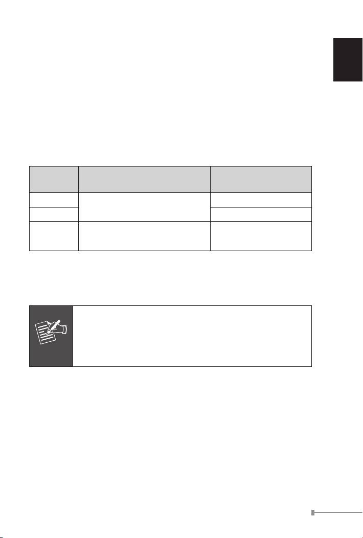
Before your installation, it is recommended to check your network
environment. The PLANET PoE Injector is with an AC-DC adapter and
inject the DC power into the pin of the twisted pair cable follow the IEEE
standard,thepowerandpinassignmentrelationshipisthetablebelow:
Required AC-DC adapter
Model
PoE Pin Assignment
Spec.
POE-151
4/5(+),7/8(-)
Input: 100~240V AC
Output: 48V DC
POE-152 1/2(+),3/6(-)
Input: 100~240C AC
POE-161
4/5(+),7/8(-)
Output: 56V DC
Category 5/5e/6 UTP/STP cable that with 8-wire are required for the
installation. UTP cable with 4-wire (pin 1/2, 3/6) can not work with
POE-151/161 and only can work with POE-152 in 10/100Base-TX
Ethernet.
1-3
Note
PLANET PoE Injector and PLANET PoE Splitter (ex.
POE-151S, POE-152S and POE-162S) can be installed
in pair. Use of third-party device is allowed if the device
complied with IEEE 802.3at or IEEE 802.3af standard.
5.2 PoE Injector Installation
1. Connect a standard network cable from Switch/workstation to
“Ethernet” port of PoE Injector.
2. Connect the long cable that will be used to connect to the remote
device to the port “Ethernet+DC”.
3. Connect the AC adapter to “DC 48V” of POE-151/POE-152. The
power LED will be steady on. Connect the AC adapter to “DC 56V” of
POE-161. The power LED will be steady on.
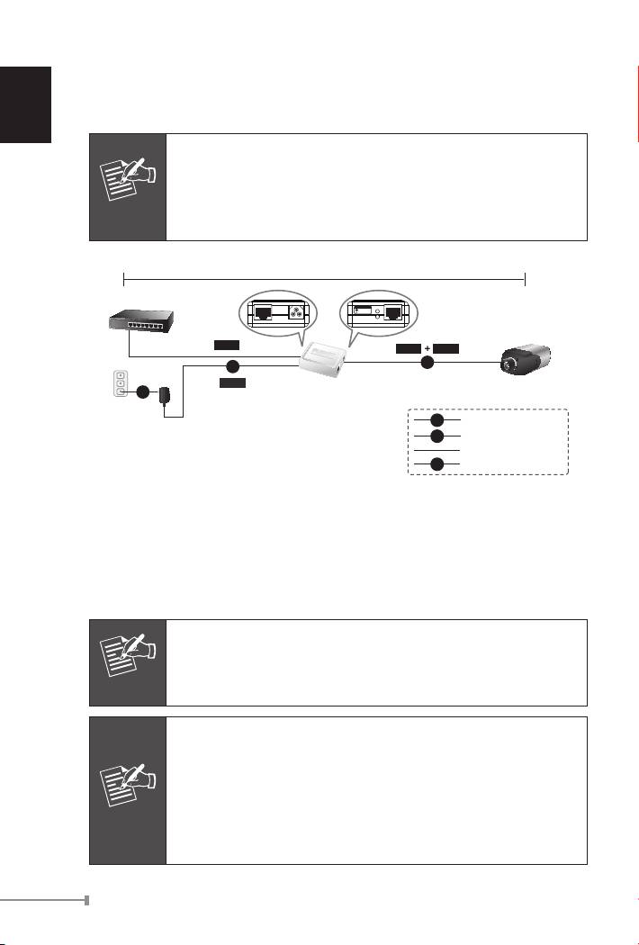
4.Connect with IEEE 802.3af devices. Base on IEEE 802.3af standard,
the POE-151/POE-152 can directly connect with any IEEE 802.3af
end-nodes like wirelessaccess point, VoIP phones and IP camera that
support IEEE 802.3af Power over Ethernet interface.
English
1-4
Note
ForPOE-161,baseonIEEE802.3atstandard,thePOE-161
can directly connect with any IEEE 802.3at end-nodes such
as PTZ (Pan, Tilt & Zoom) IP camera, Speed Dome, high
power consumption wireless LAN access point that support
IEEE 802.3at Power over Ethernet port.
100 meters
Ethernet Switch
PoE-IEEE 802.3af
Ready
PoE
Power in-use
Ethernet
48V DC
PWR
Ethernet+DC
Data
Data
Power
PoE
DC
Power
POE-151/152
PoE IP Camera
AC
PoE Injector
DC
Power Line (DC)
AC
Power Line (AC)
100Base-TX UTP
PoE
100Base-TX UTP with PoE
Figure 3: Connection to IEEE 802.3af Device
5. Once POE-151/POE-152 detects the existence of an IEEE 802.3af
device, the LED indicator will be steady ON to shows it is providing
power. The same to POE-161 that detects the existence of an IEEE
802.3at / af device.
Note
If the connected device is not fully complying with IEEE
802.3af standard, the LED indicator of POE-151/POE-152
will not be steady on.
Note
1. Since the POE-161 PoE port supports 56V DC PoE
power output, please check and assure the Powered
Device (PD) acceptable DC power range is from 52 to
56V DC. Otherwise, it will damage the Powered Device
(PD).
2. If the connected device is not fully complying with IEEE
802.3at / af Power over Ethernet, the LED indicator of
POE-161 will not be steady on.
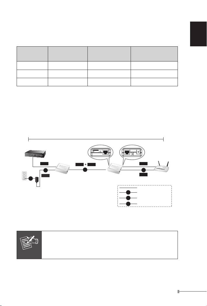
5.3 PoE Injector and PoE Splitter Installation
English
FornonPoEremotedeviceorEthernetequipment,thePoE Injector and
PoE SplittercanrunsinpairtoprovideDCPowerforthosedevices,the
table below shows the model of PLANET PoE Splitters:
Model PoE Standard DC Power Out Pass-thru. Speed
POE-151S IEEE 802.3af 5V / 12V DC 10/100Mbps
POE-152S IEEE 802.3af 5V / 12V DC 10/100/1000Mbps
POE-162S IEEE 802.3at 12V / 24V DC 10/100/1000Mbps
1.Followstep1,step2andstep3ofSection5.2fortheconnection.
2. Connect the UTP cable in the package from “Ethernet” of the PoE
splitter to the RJ-45 port of remote device.
3. Connect proper DC plug from “DC OUT” of PoE Splitter to the remote
device.
1-5
100 meters
Ethernet Switch
PoE-IEEE 802.3af
Ready
PoE
Power in-use
Ethernet+DC
Ethernet
5V 12V
DC OUT
Data
Data
Power
Data
DC
PoE
DC
Power
Power
Wireless AP
POE-151/152
POE-151S
AC
PoE Injector
PoE Splitter
100Base-TX UTP
DC
Power Line (DC)
AC
Power Line (AC)
PoE
100Base-TX UTP with PoE
Figure 4: Connection Architecture via PoE Injector and PoE Splitter
Note
Please ensure the PoE Splitter output voltage is correct
before applying power to remotedevice otherwise, it may
damage the remote device.
Оглавление
- IEEE 802.3at / af Power over Ethernet Injectors Injecteurs Ethernet la norme IEEE 802.3at / af IEEE 802.3at / af Strom über Ethernet Injektoren Power over Ethernet Injectors IEEE 802.3at / af IEEE 802.3at / af Energia para Injectores Ethernet через Power over Ethernet IEEE 802.3at / af Инжекторы Inyectores IEEE 802.3at / af Energía sobre Ethernet POE-151 / POE-152 / POE-161 User’s Manual
- Table of Contents
- 1. Overview
- 3. Product Outlook
- 5. Hardware Installation
- 6.ProductSpecication
- 1. Vue d’ensemble
- 3. Détail du produit
- 5. Installation du matériel
- 6. Caractéristiques du produit
- 1. Überblick
- 3. Produkt Ansicht
- 5. Hardware Installation
- 6.ProduktSpezikation
- 1. Informazioni generali
- 3. Vista del Prodotto
- 5. Installazione
- 6.SpecichedelProdotto
- 1. Apresentação
- 3. Apresentação do Produto
- 5. Instalação do equipamento
- 6.EspecicaçãodoProduto
- 1.Обзор
- 3.Внешнийвидпродукта
- 5.Установкаоборудования
- 6.Характеристикипродукта
- 1. Información general
- 3. Vista general del Producto
- 5. Instalación del hardware
- 6.EspecicacióndeProducto
