BURY AC-5120: F
F: BURY AC-5120
14
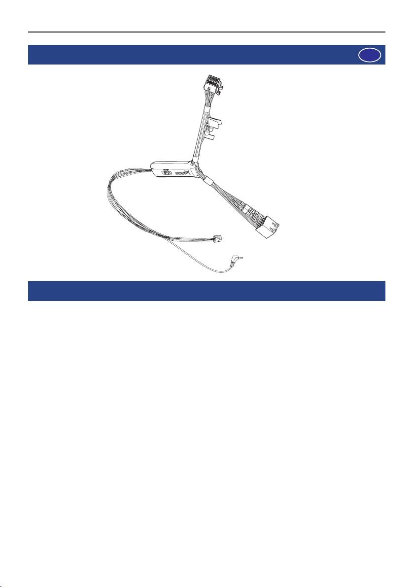
1. Fourniture
2. Mode d’installation
La boîte de commutation AC 5120 pour haut-parleurs vous permet de baisser le volume de votre radio/
lecteur CD etc. pour diffuser la voix de votre correspondant téléphonique sur les haut-parleurs de
votre autoradio. Il n’est ainsi plus nécessaire d’installer un haut-parleur supplémentaire. Si votre radio
est équipée d’une fonction de sourdine, c’est la radio qui coupe le son des haut-parleurs du véhicule
(fonction Mute). Si votre autoradio ne dispose pas d’une telle fonction, c’est la boîte de commutation
pour haut-parleurs qui s‘en charge.
Les bornes de raccordement de l’AC 5120 permettent de l‘utiliser sur les kits mains-libres BURY, qui
garantissent une tension d’alimentation par fiche Molex et possèdent une sortie de haut-parleurs. Lors
d’une conversation téléphonique en mode mains libres, votre autoradio est automatiquement mis en
sourdine (veuillez consulter le mode d’emploi du kit mains libres pour savoir comment l’utiliser). La
boîte de commutation utilise un ou deux haut-parleurs de l’autoradio, même lorsque la radio n’est pas
allumée. Ces fonctions sont automatiquement activées par l’installation de la boîte et ne doivent pas
faire l’objet d’une sélection ou d’un réglage supplémentaire.
Certains téléphones mobiles sont incompatibles avec la fonction de mise en sourdine de l’autoradio.
Pour en apprendre davantage, veuillez lire intégralement le mode d’emploi de votre téléphone mobile.
Pour de plus amples informations, adressez-vous à votre revendeur, consultez le site Internet
www.bury.com ou contactez notre hotline par téléphone.
F

15
Après avoir vérifié que tous les câbles sont de bonne longueur, décidez de l‘endroit où vous pourrez
placer la boîte de commutation. Fixez ensuite la boîte de commutation de manière à ce qu’elle ne
puisse pas tomber ou heurter d’autres objets.
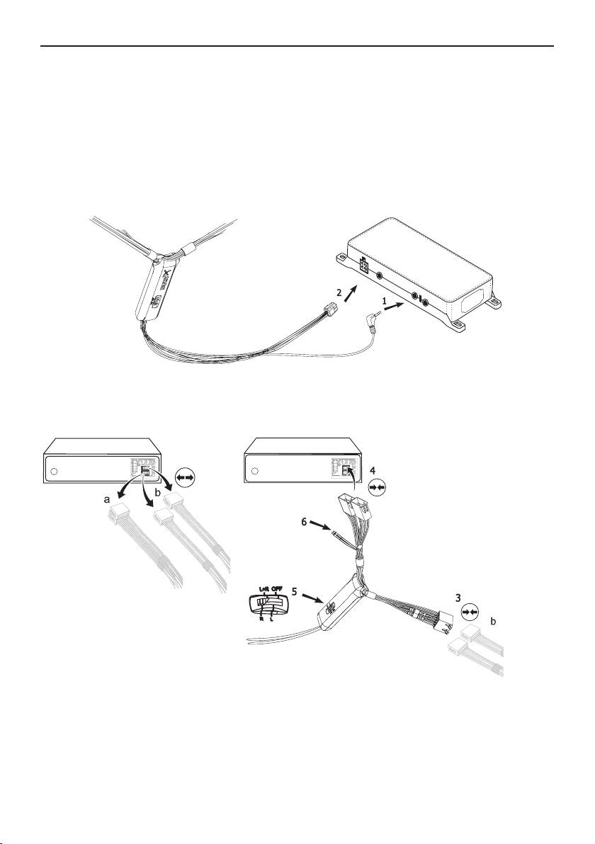
Branchez à présent la fiche à jack de 3,5mm (1) à la boîte électronique (l’autre prise plus petite est
destinée à la fiche à jack du micro). Branchez maintenant le connecteur de sortie d’alimentation de
sortie (blanc) de la boîte de commutation (2) dans la prise d’alimentation de la boîte électronique.
Retirez la fiche de haut-parleurs (a) ou (b) de la prise correspondante à l‘arrière de la radio. Raccordez
cette ou ces fiches à la prise correspondante (3) sur l’AC 5120. Branchez à présent la fiche (4) à la
radio.
En fonction de la position du switcher (5), la voix de l’interlocuteur sera restituée par le haut-parleur
avant droit, le haut-parleur avant gauche ou les deux haut-parleurs avant. Optez pour la position « OFF
» si la boîte de commutation est branchée à la radio via le câble « Phone-IN » (6).
16
Les deux câbles « Phone-In » sont marqués en conséquence et doivent être insérés dans les
fiches (bleu, vert ou jaune) correspondant aux raccords sur la radio. A cet égard, nous vous pri-
ons de tenir compte des descriptions concernant l’attribution des raccords de votre autoradio
dans le mode d’emploi correspondant. Sur de nombreux autoradios, il est possible de régler le
volume (de la voix de l’interlocuteur) via l’entrée Phone-In et la sélection du haut-parleur.
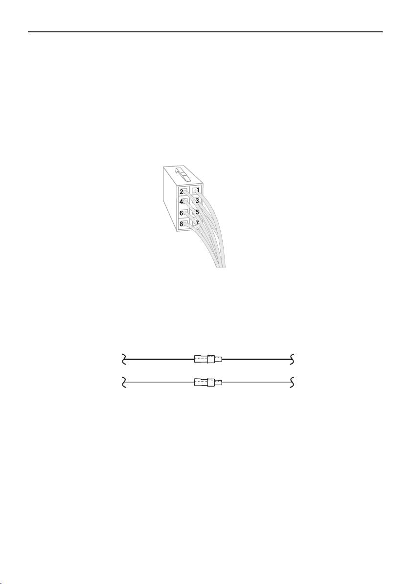
Différents raccordement du connecteur ISO à la radio
L’attribution des broches du connecteur ISO utilisé varie en fonction du modèle de véhicule. Avant
d’utiliser la boîte de commutation, assurez-vous que l’attribution des broches est adaptée afin
d’éviter des dommages.
Configuration I
Si la broche 7 du connecteur ISO est raccordée à l‘alimentation en courant continu et la broche 4 à
l’allumage, veuillez vérifier que le raccordement est identique au schéma représenté ci-dessous.
rouge 7 (rouge)
Boîte de commutation Véhicule
bleu 4 (bleu)

17
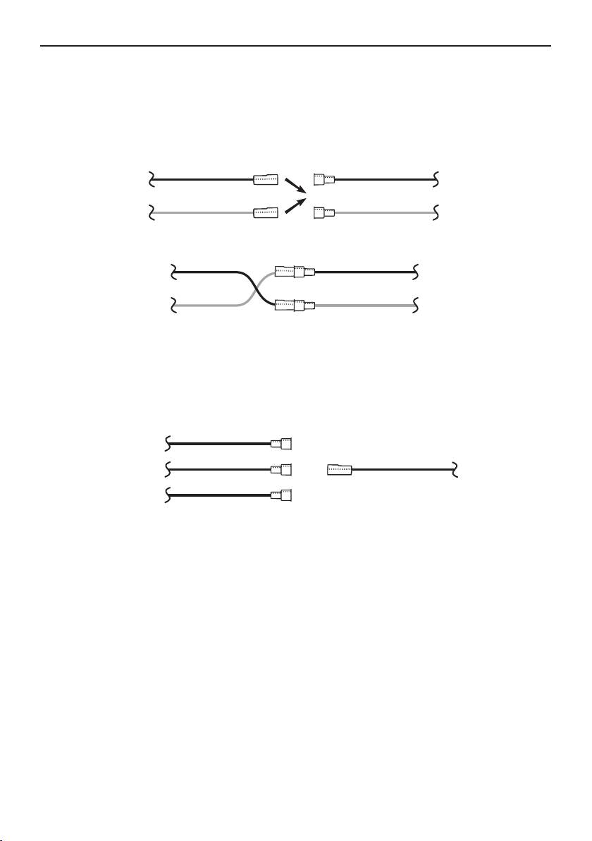
Configuration II
Si la broche 7 du connecteur ISO est raccordée à l’allumage et la broche 4 à l’alimentation en courant
alternatif, veuillez vérifier que le raccordement est identique au schéma représenté ci-dessous.
rouge 7 (rouge)
Boîte de
Véhicule
commutation
bleu 4 (bleu)
rouge 7 (rouge)
Boîte de
Véhicule
commutation
bleu 4 (bleu)
Consultez le mode d’emploi de l’autoradio pour connaître la broche attribuée au signal « sourdine »
(mute). Ce signal peut apparaître à l’un des trois câbles portant les identifications « mute1 »,
« mute2 », « mute3 ».
mute 1
mute (jaune)
mute 2
l’autoradio Boîte de
commutation
mute 3
Raccordez le câble jaune de sourdine de la boîte de commutation au bon câble de l’autoradio :
« mute 1 », « mute 2 » ou « mute 3 ».
ATTENTION :
Les lignes plus et d’allumage sont protégées par des fusibles 3A dans le boîtier de la X
boîte de commutation.

18
1. Toimitusmäärä
2. Asennusohje
Kaiutinvaihtokytkimen AC 5120 avulla on mahdollista vaimentaa radiovastaanottimen / CD-soittimen
jne. ääni ja siirtää puhelu kuulumaan ajoneuvon kaiuttimista. Näin vältytään ylimääräisen kaiuttimen
asentamiselta. Jos radiovastaanottimessa on hiljaiseksikytkemistoiminto, radio huolehtii ajoneuvokai-
uttimien hiljentämisestä (mute-toiminto). Jos autoradiossa ei ole kyseistä toimintoa, signaalit vaimen-
netaan kaiutinvaihtokytkimessä. AC 5120:ä voi käyttää liitäntöjensä ansiosta yhdessä BURY kaiutinto-
imintolisälaitteen kanssa, joka syöttää virtaa molexpistokkeen kautta, ja jossa on kaiutinlähtö.
Kun puhelinkeskustelu toteutetaan kaiutintoiminnolla, autoradio hiljennetään automaattisesti (kaiutin-
toimintolaitteen tarkka käyttö löytyy kaiutintoimintolaitteen käyttöohjeesta). Vaihtokytkin käyttää nyt
yhtä tai kahta autoradion kaiuttimista, vaikkei radio olisi päällekytkettynä. Nämä toiminnot aktivoituvat
asennustavan vuoksi automaattisesti, eivätkä ne tarvitse erillisiä käyttö- tai valintatoimenpiteitä.
Jotkut matkapuhelimet eivät tue radion hiljennystoimintoa. Tarkoitusta varten on syytä lukea matkapu-
helimen käyttöohje. Tarkempia tietoja saa laitekauppiaalta, internetistä osoitteesta www.bury.com tai
puhelimitse Hotline-palvelustamme.
FIN

19
Kaikkien kaapelipituuksien tarkistamisen jälkeen voi päättää, mihin vaihtokytkimen voi asentaa. Tämän
jälkeen vaihtokytkin kiinnitetään siten, että se ei pääse liikkumaan, tai että se ei kolise muita esineitä
vasten.
Tämän jälkeen liitetään 3,5 mm jakkipistoke (1) elektroniikkarasiaan. (Toinen pienemmistä holkeista on
varattu mikrofonin jakkipistokkeelle.) Sitten työnnetään lähtevä, vaihtokytkimen (2) valkoinen virran-
syöttöpistoke elektroniikkarasian virransyöttöholkkiin.
Nyt vedetään (a) tai (b) kovaäänisjohto pois kovaäänispistokkeesta radion takaosassa. Yhdistetään
sopivalla kiinnityksellä (3) varustettu pistoke (pistokkeet) AC 5120:een. Seuraavaksi pistoke (4) yhdis-
tetään radioon.
Kytkinpaikasta riippuen (5) puheluääni kuuluu nyt oikeanpuoleisesta kaiuttimesta edessä, vasemman-
puoleisesta kaiuttimesta edessä tai molemmista etummaisista kaiuttimista. Valitaan ”OFF“ (POIS
PÄÄLTÄ) jos vaihtokytkin liitetään radioon ”Phone-In“ -kaapelilla (6) (puhelin-tulokaapelilla).

20
Kaksi ”Phone-In“ -kaapelia on merkitty, ja ne on liitettävä vastaavasti radion liitäntäpistokkeisiin
(sininen, vihreä tai keltainen). Tässä on otettava huomioon ohjeet autoradion liitännöistä radion
käyttöohjeessa. Monissa autoradioissa kaiutin voidaan valita ja äänenvoimakkuutta voi säätää
(puheluäänen toisto) Phone-In (puhelin sisään) -tuloliitännässä.
Eri ISO-pistokkeen liitäntöjä radiovastaanottimessa
Käytetyn ISO-pistokkeen nastojen liitännät vaihtelevat ajoneuvokohtaisesti. Ennen vaihtokytki-
men käyttöä on vahinkojen välttämiseksi varmistuttava, että liitännät ovat sopivat.
Kokoonpano l
Jos ISO-pistokkeen nasta (7) on liitetty tasavirran syöttöön ja nasta (4) sytytykseen, on tarkis-
tettava onko liitäntä alla olevan piirroksen mukainen.
punainen 7 (punainen)
Vaihtokytkin Ajoneuvo
sininen 4 (sininen)
21
Kokoonpano ll
Jos ISO-pistokkeen nasta (7) on liitetty sytytykseen ja nasta (4) vaihtovirransyöttöön, on tarkistettava
onko liitäntä alla olevan piirroksen mukainen.
punainen
7 (punainen)
Vaihtokytkin
Ajoneuvo
sininen 4 (sininen)
punainen 7 (punainen)
Vaihtokytkin
Ajoneuvo
sininen 4 (sininen)
Radiolaitteen käyttöohjeessa on nastojen kytkentämerkinnät signaalivaimennukselle (mute). Tämä si-
gnaali voi esiintyä yhdessä kaapeleista, jotka on merkitty ”mute1”, ”mute2”, ”mute3”.
mute 1
mute (keltainen)
mute 2
Autoradio Vaihtokytkin
mute 3
Vaihtokytkimen keltainen mute-kaapeli kytketään autoradion oikeaan “mute1”, “mute2” tai “mute3” -
kaapeliin.
HUOMIO:
Plus- ja sytytysjohdot on suojattu 3 A:n varokkeilla vaihtokytkimen kotelossa. X
22
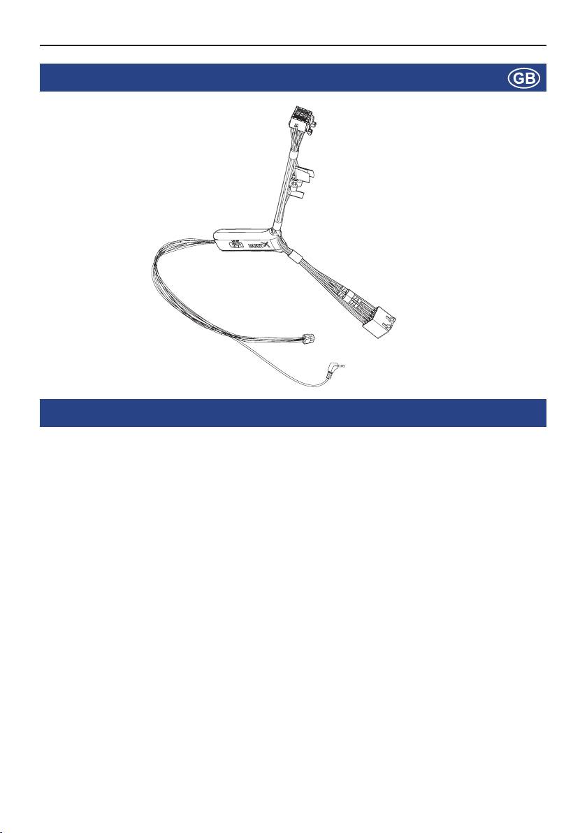
1. Scope of supply
2. Installation instructions
With the AC 5120 speaker switchbox, you get the possibility of being able to mute the feedback of your
car radio / CD player etc. and to transfer the voice output of your conversation partner during a tele-
phone call to your vehicle’s speakers. This means that the installation of additional speakers isn‘t re-
quired. If your radio has a mute function, then the vehicle speakers are turned onto mute using the
radio. If your car radio doesn‘t have this function, then the signals will be suppressed by the speaker
switchbox. You can use the AC 5120 through the connections that your BURY hands free car kit offers,
which guarantee voltage supply via molex plugs and also have a speaker output.
If you want to make a telephone call in the hands-free mode, your car radio will be automatically swit-
ched on to mute (for the exact operation of your hands free car kit, please read your HFCK user ma-
nual). The Audio switchbox now uses one or two loudspeakers in your car for the telephone conversa-
tion, even if your radio is switched off. This function will be automatically activated after the installati-
on of the unit, there are no subsequent manual settings required.
Some mobile phones do not support a radio mute function. Please read your telephone user manual
for more details. You can find out more detailed information at your specialist retailer, in the internet
under www.bury.com, or over our telephone hotline.
23
After checking that all the cable lengths are sufficient, decide where you are able to attach the Audio
switchbox. Now secure the Audio switchbox so that it isn’t able to flap about and/or rattle against other
parts of your vehicle.
Now connect the audio switchbox plug (1) to the hands-free car kit. (The other, smaller box is used by
the audio switchbox plug for the microphone.) Now connect the white power out cable connector (2)
of your Audio switchbox to the power supply socket of your hands-free kit.
Now disconnect the (a) and/or the (b) loudspeaker connector from the speaker socket on the radio at
the back. Connect this connector with the suitable socket (3) on the AC 5120. Now connect the plug
(4) with the radio.
Depending on the switcher position (5), the voice of your conversation partner will be fed back through
either the front right speaker, the front left speaker, or through both of the front loudspeakers. The
‘OFF’ position is to be selected if you connect the switchbox to the radio using the ‘Phone-IN’ cable
(6).

24
The two ‘Phone-In’ cables are marked accordingly and must be plugged into the appropriate con-
nections on the radio (blue, green or yellow). In this regard, please refer to the instructions
concerning the connection configuration of your car radio in your car radio handbook. In lots of
radios, the volume level (feedback of your conversation partner) can be controlled via the phone
input and the selection of the loudspeaker.
Different connections of the ISO plug on the radio
The layout of the pins on the ISO plug used in a car depends on the type of car. Before using the
switchbox, you should make sure that the connections are correct in order to prevent possible
damage to the device.
Configuration I
If the assignment of pin 7 of the ISO plug is connected to the DC Power Supply, and pin 4 is
connected to the ignition, you should check if the connection looks like the connection presented
on the drawing below.
red 7 (red)
Switchbox Vehicle
blue 4 (blue)

25
Configuration II
If the assignment of pin 7 of the ISO plug is connected to the ignition, and pin 4 is connected to the
DC power supply, the connection of the cables should look like the connection presented on the dra-
wing below.
red 7 (red)
Switchbox
Vehicle
blue 4 (blue)
red 7 (red)
Switchbox
Vehicle
blue 4 (blue)
In the operating manual of the radio device, you can find the pin assignment for the “mute” signal. This
signal can occur on one of three cables marked with “mute1”, “mute2”, or “mute3”.
mute 1
mute (yellow)
mute 2
radio device Switchbox
mute 3
Connect the yellow “mute” cable to the switchbox using the correct cable from the car radio: “mute 1”,
“mute 2” or “mute3”.
ATTENTION:
The positive wires and ignition wires are protected in the casing of the switchbox with X
3A fuses.
