HP Designjet 10000s Printer series: Figure 4 3.3.2 IInsert tthe nnew ffilter(s) Figure 5 Figure 6 Figure 7
Figure 4 3.3.2 IInsert tthe nnew ffilter(s) Figure 5 Figure 6 Figure 7: HP Designjet 10000s Printer series
Table of contents
- I Introduction
- II Product ddescription
- III Safety III 11 General iinformation III 22 Use aas iintended III 33 Information oon ssigns aand ssymbols
- III 44 Warnings
- III 55 Warnings ffor mmaintenance III 66 Protective eequipment
- Index
- 1 Installation && FFunction DDescription 1.1 Warnings ffor mmaintenance
- 1.2 Unpacking aand iinstallation 1.3 Box ccontent
- 1.4 Connection oof tthe pprinter 1.5 Power oon tthe AAPS 1.6 Function ddescription
- 2 Operation 2.1 Operating cconditions 2.2 Operation
- 2.3 Test ooperation
- Designation
- Figure 1 Figure 2 Figure 3
- Figure 4 3.3.2 IInsert tthe nnew ffilter(s) Figure 5 Figure 6 Figure 7
- 3.4 Enter tthe ccode oof tthe nnew rreplacement ffilter 3.4.1 HHP DDesignjet 88000s AAir PPurifier SSystem
- 3.4.2 HP DDesignjet 99000s/10000s AAir PPurifier SSystem
- 4 Disposal
- 5 Troubleshooting
- 6 Legal iinformation
- 6.Your exclusive remedies for defective HP products are the following:
- B. Limitations of liability C. Local law
- 7 Regulatory nnotices 7.1 Regulatory mmodel nnumber 7.2 Regulatory sstatements
- 9 Technical ddata
• Grasp the handle of the filter element and pull the
filter element out of the filter housing (Fig. 4) while
it stands securely in the filter housing. You can secu-
rely grasp under filter element with both hands and
then place it down carefully.
Note
: Each filter element weights approx. 16 kg.
Figure 4
Immediately dispose of the used filter element. Used filters capture an organic solvent (ethylene
glycol monobutyl ether acetate, CAS No. 112-07-2) and other chemicals from ink vapors. When
disposing used filter cartridges it is your responsibility to observe all local, state, and federal
regulations related to the handling, use, storage, and disposal of organic solvents.
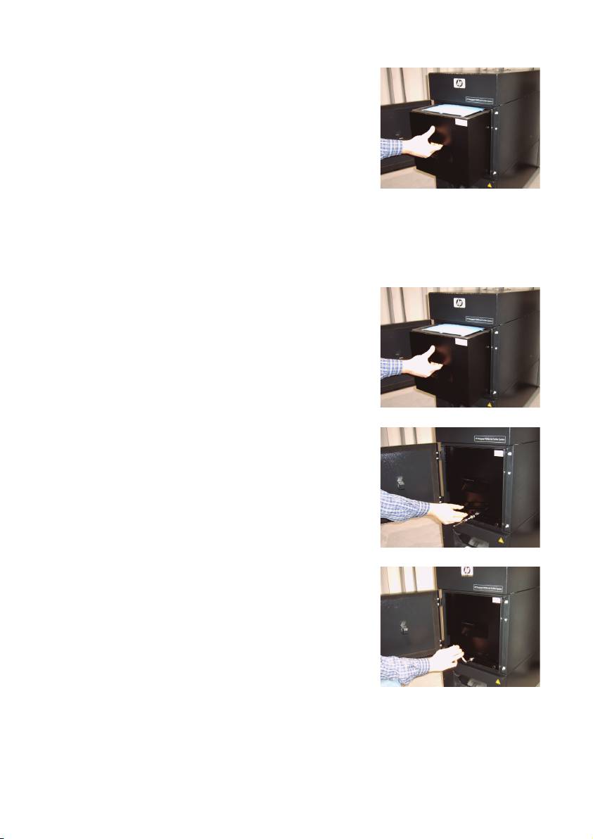
3.3.2 IInsert tthe nnew ffilter(s)
Please, proceed as follows:
• Remove the new filter element(s) from the packaging.
• Store the enclosed flyer with the code in a safe place.
You will need this later to reset the service interval.
• Push the filter element(s) (Fig. 5) into the filter housing
up to the stop. The surrounding gasket on the filter
element must be at the top, and the handle of the fil-
ter element must point towards the service opening.
Figure 5
• Put the filter locking. (Fig.6)
Figure 6
• Tighten the sealing lifting mechanism (Fig. 7) by tur-
ning the adjusting screw until it is completely tight.
• Insert the screwing key into the intake again.
• Close the service door until the latch engages.
Figure 7
Note:
Always pay attention that the surrounding gasket on the filter element(s) and on the pre-filter tray
at the top is pushed into the stop, and the adjusting screw is completely tight. Otherwise, this
can lead to leakages and the extracted gases and dust will not be filtered properly.
17HP Air Purifier System
