HP Designjet 10000s Printer series: 1.2 Unpacking aand iinstallation 1.3 Box ccontent
1.2 Unpacking aand iinstallation 1.3 Box ccontent: HP Designjet 10000s Printer series
Table of contents
- I Introduction
- II Product ddescription
- III Safety III 11 General iinformation III 22 Use aas iintended III 33 Information oon ssigns aand ssymbols
- III 44 Warnings
- III 55 Warnings ffor mmaintenance III 66 Protective eequipment
- Index
- 1 Installation && FFunction DDescription 1.1 Warnings ffor mmaintenance
- 1.2 Unpacking aand iinstallation 1.3 Box ccontent
- 1.4 Connection oof tthe pprinter 1.5 Power oon tthe AAPS 1.6 Function ddescription
- 2 Operation 2.1 Operating cconditions 2.2 Operation
- 2.3 Test ooperation
- Designation
- Figure 1 Figure 2 Figure 3
- Figure 4 3.3.2 IInsert tthe nnew ffilter(s) Figure 5 Figure 6 Figure 7
- 3.4 Enter tthe ccode oof tthe nnew rreplacement ffilter 3.4.1 HHP DDesignjet 88000s AAir PPurifier SSystem
- 3.4.2 HP DDesignjet 99000s/10000s AAir PPurifier SSystem
- 4 Disposal
- 5 Troubleshooting
- 6 Legal iinformation
- 6.Your exclusive remedies for defective HP products are the following:
- B. Limitations of liability C. Local law
- 7 Regulatory nnotices 7.1 Regulatory mmodel nnumber 7.2 Regulatory sstatements
- 9 Technical ddata
1.2 Unpacking aand iinstallation
Note:
When the APS is installed, allow adequate space for exhaust hoses from the printer. Lo-
cate these hoses and the APS so that they do not pose a trip hazard or interfere with the opera-
tion of the printer such as loading and unloading media, replacing Ink Cartridges, inspecting
and replacing the Waste Ink Bottle.
Note:
Allow adequate space around the APS to remove and replace the filter elements.
Note:
Do not install the APS in an area where it receives direct airflow from air conditioners,
heaters, or ventilators.
Note:
Proceed as follows when unpacking and installing the APS:
– Do not lift the APS off the wooden pallet or remove from the transport packaging
until you reach the place of installation. Carefully remove the packaging.
– Check the completeness of the delivery based on the packing list. Also check the
complete delivery for external damages, such as may have occurred in transit.
– Move the APS on its casters until you reach the place of installation
– Install the APS on a level, firm surface.
– Secure the APS against unintended rolling by pressing the brakes on the casters.
– The APS must be placed in such a way that the exhaust grid can lead the filtered
air back into the working room.
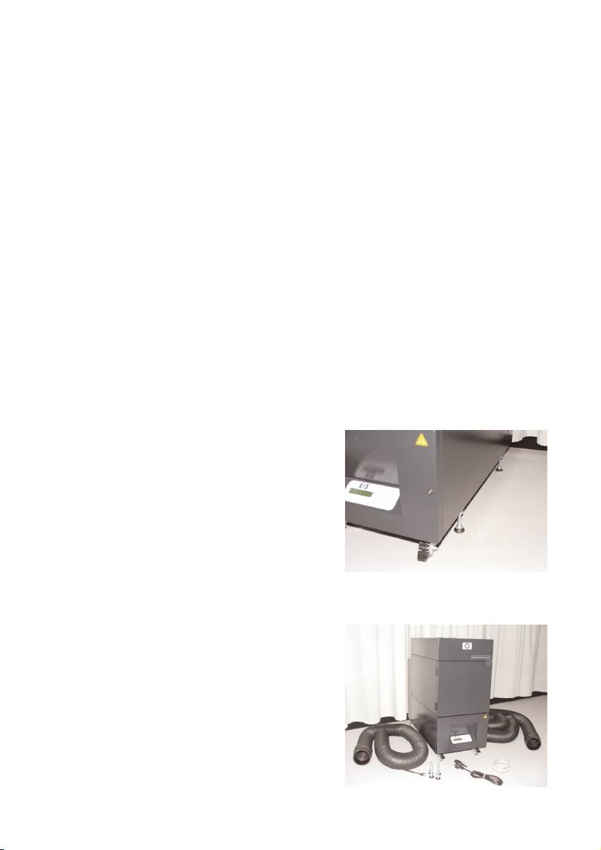
– Secure the APS with placing of the adjustment feet to prevent the APS for uninten-
tional tilting (according EN 60950-1 test of stableness) to the side. In the bottom of
the APS housing, 4 nuts are fastened for placing of the adjustment feet. To be able
to screw the adjustment feet into the 4
nuts it is necessary to remove the 4 exi-
sting screws M10.
The positioning of the adjustment feet has
to be according to the underground in
such a way that the APS is placed on an
even and firm underground and the exi-
sting wheels are not relieved.
1.3 Box ccontent
When you receive the APS please check in detail the box content. The regular scope of delivery
includes:
– APS, complete (with built-in filter ele-
ments);
– Hose set I (4 m hose, 2 m hose; respec-
tively incl. connection stubs and clamping
hoses)
–Power cord
You can receive more than one, please
choose the proper for your need
– 4 adjustment feet M10, length: 85 mm
– 1 open-end wrench
11HP Air Purifier System
