HP Designjet 10000s Printer series: Figure 1 Figure 2 Figure 3
Figure 1 Figure 2 Figure 3: HP Designjet 10000s Printer series
Table of contents
- I Introduction
- II Product ddescription
- III Safety III 11 General iinformation III 22 Use aas iintended III 33 Information oon ssigns aand ssymbols
- III 44 Warnings
- III 55 Warnings ffor mmaintenance III 66 Protective eequipment
- Index
- 1 Installation && FFunction DDescription 1.1 Warnings ffor mmaintenance
- 1.2 Unpacking aand iinstallation 1.3 Box ccontent
- 1.4 Connection oof tthe pprinter 1.5 Power oon tthe AAPS 1.6 Function ddescription
- 2 Operation 2.1 Operating cconditions 2.2 Operation
- 2.3 Test ooperation
- Designation
- Figure 1 Figure 2 Figure 3
- Figure 4 3.3.2 IInsert tthe nnew ffilter(s) Figure 5 Figure 6 Figure 7
- 3.4 Enter tthe ccode oof tthe nnew rreplacement ffilter 3.4.1 HHP DDesignjet 88000s AAir PPurifier SSystem
- 3.4.2 HP DDesignjet 99000s/10000s AAir PPurifier SSystem
- 4 Disposal
- 5 Troubleshooting
- 6 Legal iinformation
- 6.Your exclusive remedies for defective HP products are the following:
- B. Limitations of liability C. Local law
- 7 Regulatory nnotices 7.1 Regulatory mmodel nnumber 7.2 Regulatory sstatements
- 9 Technical ddata
Note
The green LED blinks after an interval period of 700 operating hours as an indication
to order new filters, and also this means the filter elements must be replaced within
100 additional operating hours.
Caution!
When removing or inserting the filter elements it is recommended to use protective glo-
ves (disposable gloves made of polyethylene, latex or Nitrile®) before carrying out the
filters replacement and/or the suction hoses.
With the system "HP Designjet 8000s Air Purifier System" one filter element is used in the filter
unit. With the system "HP Designjet 9000s/10000s Air Purifier System" two filter elements are
placed behind each other in the filter unit. With the filter system "HP Designjet 9000s/10000s
Air Purification System" always replace both filter elements at the same time.
You should proceed as follows when replacing the filter:
3.3.1 Removal oof tthe oold ffilter(s)
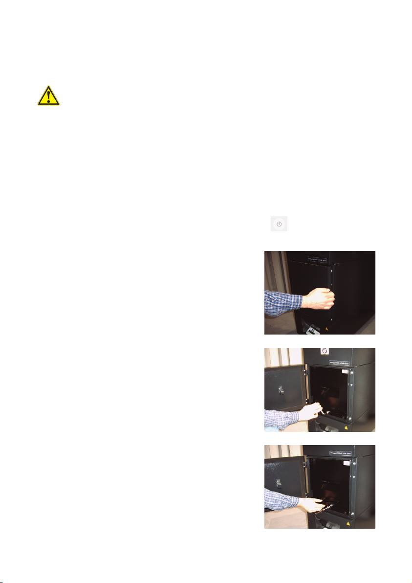
• Switch off the APS at the membrane keyboard using the button.
• Secure the APS against being switched on again unexpectedly, by removing
the power cable from the wall power socket.
• Grasp the rear right of the service flap (Fig.1) with
one hand and open this to the left.
Note:
You must overcome the resistance of the latch!
• Remove the offset screwing key from the intake.
• Slacken the sealing lifting mechanism by turning the
adjusting screw (Fig. 2) using the offset screwing key.
Turn the adjusting screw until the filter element is at
the bottom and can be shifted freely.
• Release the filter locking (Fig. 3)
16 User´s Guide
Figure 1
Figure 2
Figure 3
