Vdo WR X1: инструкция
Раздел: Автотовары
Тип: Крепление для велосипедов
Инструкция к Крепление для велосипедов Vdo WR X1
I F GB D
SERIES-X
X
D Bedienungsanleitung
GB Instruction Manual
F Manuel d‘ Installation et d‘ Utilisation
I Manuale d‘ Installazione e Funzionamento

D GB F I
X1 VDO CYCLECOMPUTING2
I F GB D
www.vdocyclecomputing.com X1 3
Vorwort
Inhaltsverzeichnis
Herzlichen Glückwunsch.
1. Display 4
5. Grundeinstellungen 10
Mit Ihrer Wahl für einen VDO Computer haben Sie sich für ein technisch sehr hochwertiges Gerät entschieden.
5.1 Sprache einstellen 10
Um das Potenzial des Computers optimal ausnutzen zu können, empfehlen wir Ihnen, diese Anleitung
2. Bedienung 6
5.2 Einstellen und Messen
sorgfältig zu lesen. Sie erhalten alle Hinweise zur Bedienung sowie viele weitere nützliche Tips.
der Radgröße 10
3. Informations-Funktionen 6
5.2.1 Einstellen über Reifentabelle 10
Wir wünschen Ihnen viel Freude beim Fahren mit Ihrem VDO Cyclecomputer.
5.2.2 Einstellen über Radumfang 12
Cycle Parts GmbH
4. Installation 8
5.3 Einstellen Uhr 13
4.1 Montage von Sonsor, Magnet
5.4 Einstellen Gesamtkilometer 14
und Lenkerhalterung 8
5.5 Umschalten von Rad 1 auf Rad 2 14
4.2 Batterieeinbau in den Computer 9
5.6 Service-Intervall-Anzeige 15
Verpackungsinhalt
4.3 Einsetzen des Computers
5.7 Sleep-Modus 16
in die Lenkerhalterung 9
5.8 Reset-Funktionen 17
Bitte prüfen Sie zunächst die Vollständigkeit dieser Verpackung:
6. Garantiebedingung 18
1 VDO Computer
1 Universal-Lenkerhalterung
Batterie eingebaut
mit Kabel und Sensor
7. Technische Spezifikationen 18
8. Fehlerbehebung 19
1 Unterleg Gummi
1 Speichenmagnet
Kabelbinder
für Sensor
(Clip-Magnet)
zur Montage der Halterung
„>>> P02“ Verweise am Anfang eines Kapitels
und des Sensors
verweisen auf das entsprechende Bild im
Picturebook!
D GB F I
X1 VDO CYCLECOMPUTING4
I F GB D
www.vdocyclecomputing.com X1 5
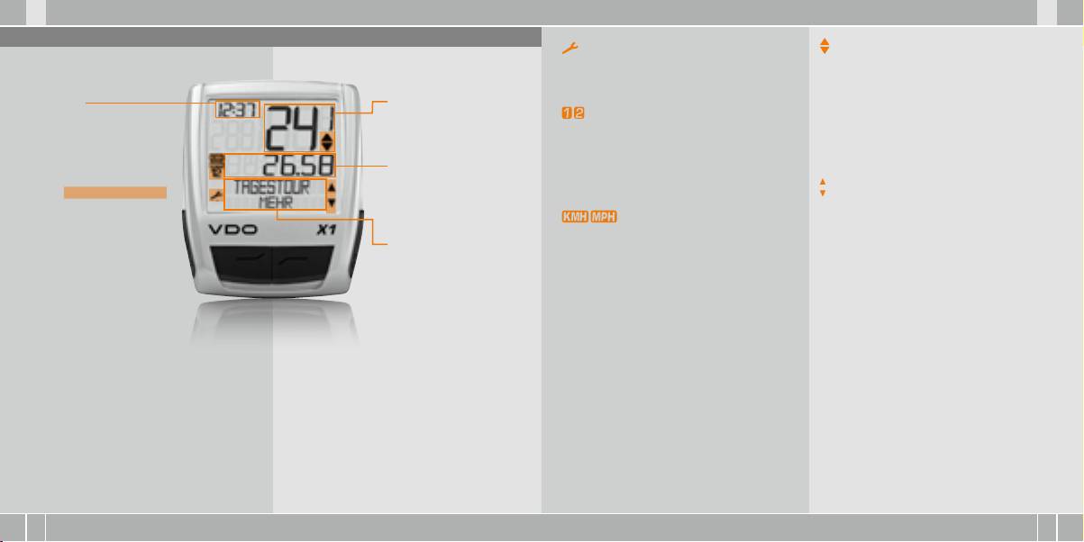
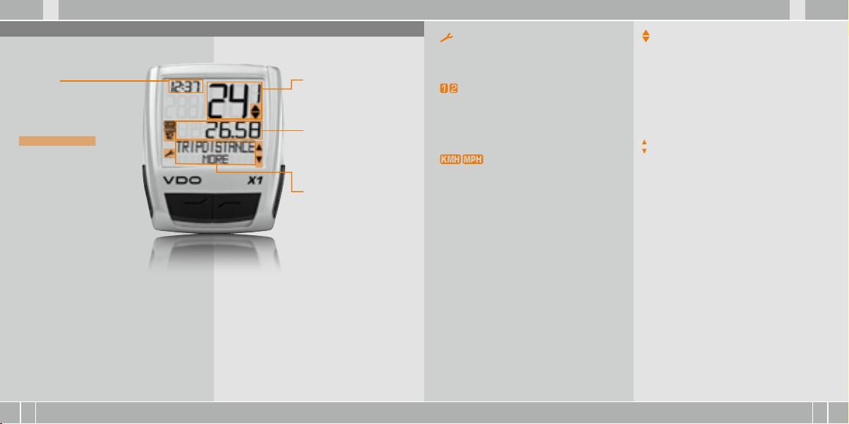
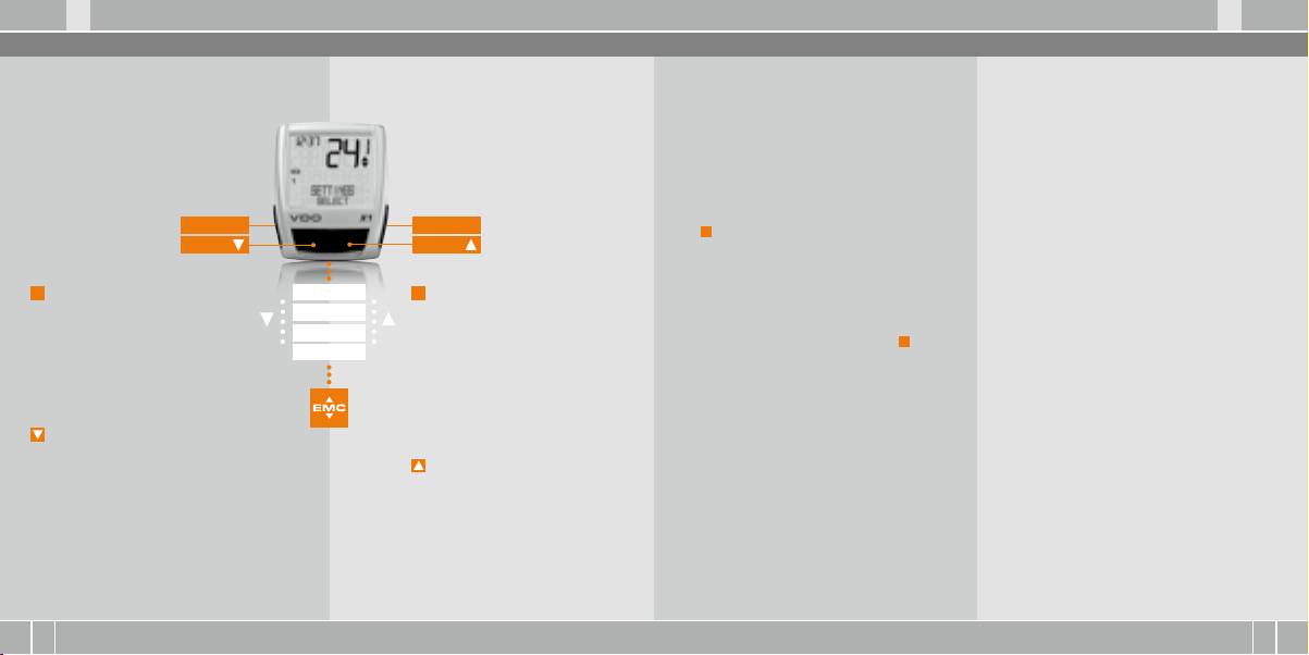
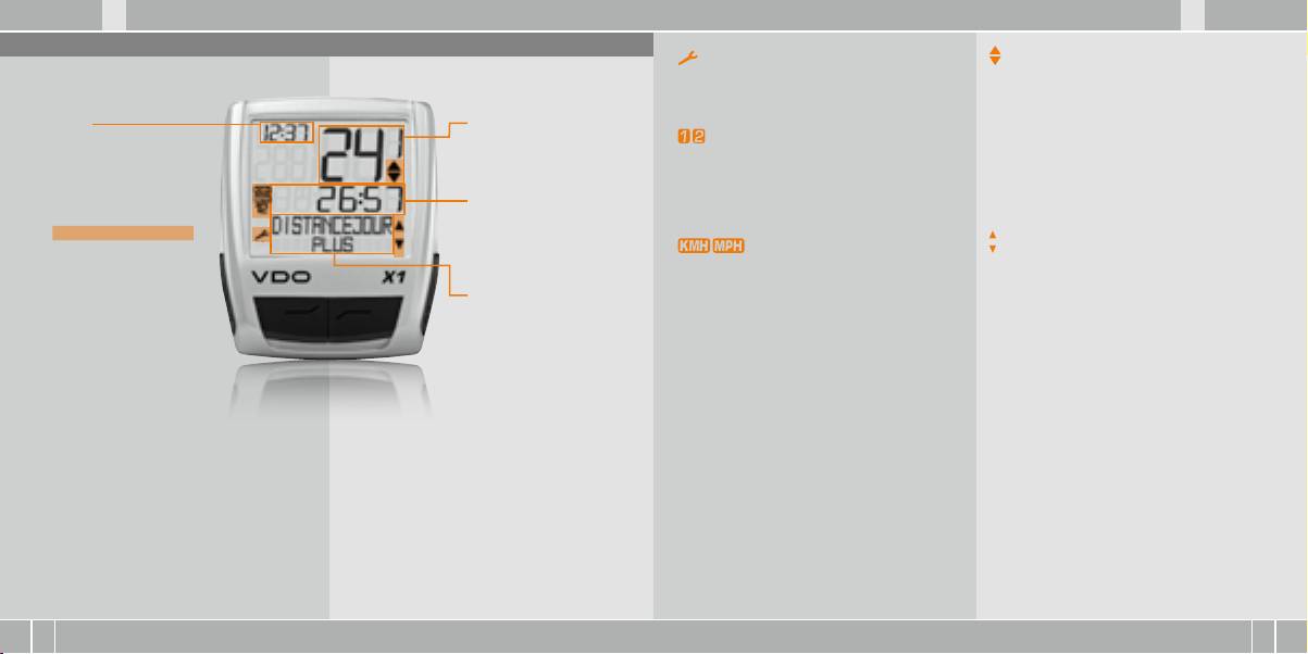
1. Display
Service Indikator
Abweichungsindikator Geschwindigkeit
Das Display kann man in
Zeigt an, dass Ihr Fahrrad zum Service sollte.
(aktuell) zu Geschwindigkeit (Schnitt)
4 Segmente gliedern:
Das Service-Intervall können Sie für Rad 1 und Rad 2
Der Computer vergleicht die aktuelle Geschwin-
individuell festlegen.
digkeit mit der Durchschnittsgeschwindigkeit.
Segment 1
Segment 2
Der Indikator zeigt an
Zeigt immer die
Zeigt die aktuelle
Indikator Rad 1/Rad 2
B
ob die aktuelle Geschwindigkeit über dem
aktuelle Uhrzeit.
Geschwindigkeit.
Der Computer kann mit zwei verschiedenen Ein-
Durchschnitt liegt (+1 km/h)
stellungen für 2 Fahrräder arbeiten. Der Indikator
B
unter dem Durchschnitt liegt (-1 km/h)
zeigt an, welches der beiden Fahrräder Sie zur
B
oder dem Durchschnitt entspricht
Segment 3
Nutzung ausgewählt haben. Die Gesamtkilome-
(Toleranz +/- 1 km/h)
Zusätzlich finden Sie im
Zeigt den Wert der von
ter werden entsprechend für Rad 1 und für Rad 2
Display Indikator-Elemente.
Ihnen gewählten Anzeige-
getrennt gezählt und gespeichert.
Menusteuerungsindikator
Die Beschreibung der einzelnen
Funktion/Information.
Wenn ein Untermenu aufgerufen wurde, blinken
Indikatoren finden Sie auf der
Messeinheit (KMH oder MPH)
diese Indikatoren und zeigen an, dass es noch
rechten Seite.
Der Computer kann sowohl KMH als auch MPH
weitere Auswahlmöglichkeiten gibt oder der Com-
Segment 4
anzeigen. Strecken werden entsprechend in Kilo-
puter auf eine Eingabe wartet (Einstell-Modus).
Zeigt in der oberen Zeile
meter oder Meilen angezeigt. Der Indikator zeigt
(Info-Zeile) die Bezeichnung
die gewählte Messeinheit an.
der gewählten Funktion.
In der zweiten Zeile (Menü-
Zeile) wird angezeigt,
B
ob es weitere Informati-
onen gibt „MEHR“
B
ob es eine weitere
Auswahlmöglichkeit
gibt „AUSWAHL“
D GB F I
X1 VDO CYCLECOMPUTING6
I F GB D
www.vdocyclecomputing.com X1 7
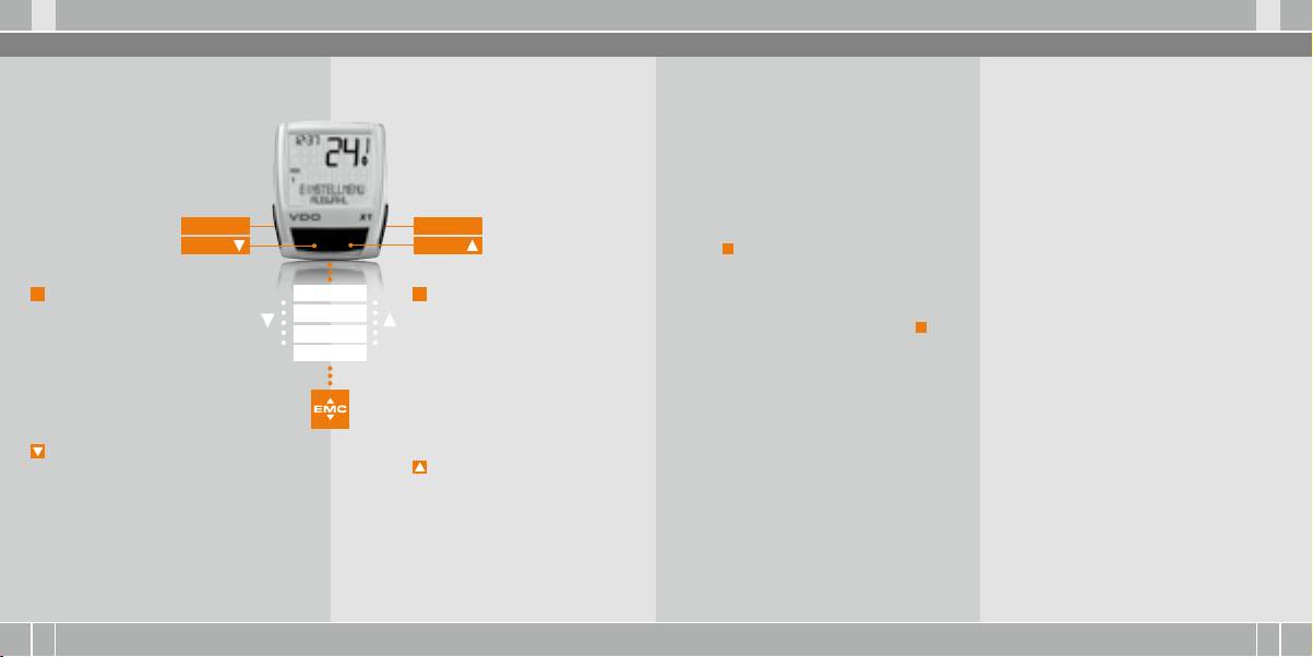
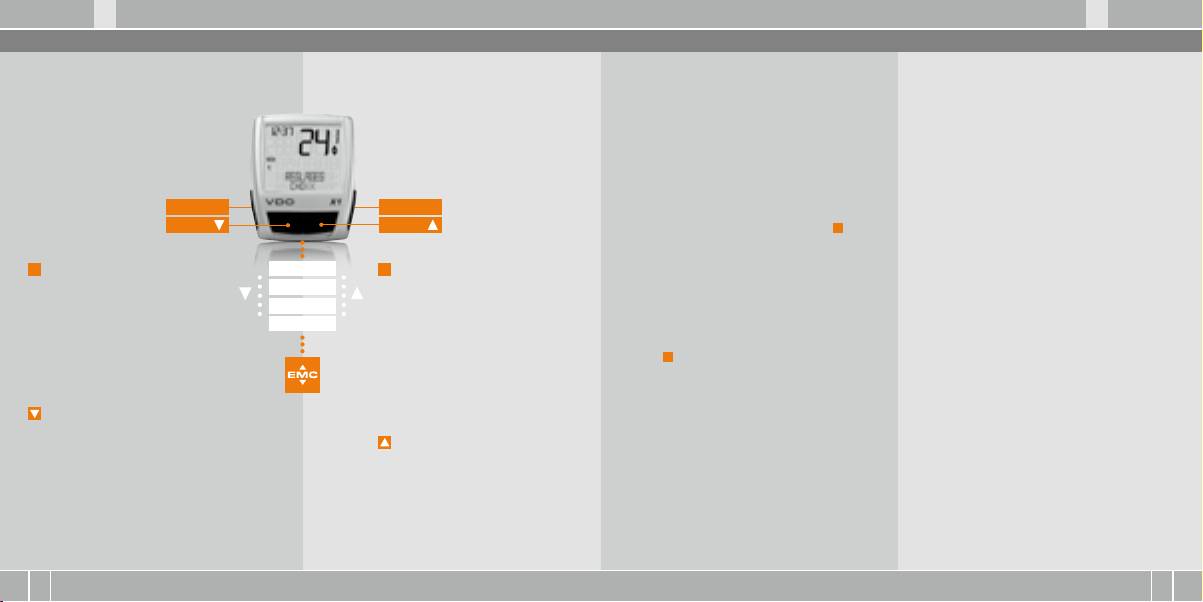
2. Bedienung
3. Informations-Funktionen
Für die einfache Bedienung Ihres Computers haben
Menü-Indikatoren im Display zeigen durch Blinken
TAGESTOUR
DSCHN GSCHW
wir das EMC = Easy Menu Control System entwickelt.
an, dass es weitere Auswahlmöglichkeiten gibt. Im
Zeigt die Strecke der aktuellen Tour seit dem letzten
Zeigt die Durchschnittsgeschwindigkeit, berechnet
Das EMC erleichtert die Bedienung des Computers
Funktions-Modus und im Einstell-Modus erfolgt
Reset. Maximalwert 999,99 km.
aus Tagestour und Fahrzeit, seit dem letzten Reset.
über eine Volltext-Menüführung wie sie
die Bedienung über die 4 Tasten.
Bei Überschreiten des Maximalwertes beginnt der
Genauigkeit: 2 Kommastellen.
bei den meisten Handys verwendet wird.
Zähler wieder bei Null. Gleichzeitig werden die
Die Durchschnittsgeschwindigkeit wird neu berech-
Werte für Fahrzeit und Durchschnittsgeschwin-
net, wenn die Tagestour oder die Fahrzeit den
digkeit auf Null zurückgesetzt.
Maximalwert übersteigt.
TAGESTOUR/MEHR
MAX GSCHW
MEHR zeigt an, dass es zum Hauptmenu TAGES-
Zeigt die Maximalgeschwindigkeit auf der aktuellen
C = CLEAR
M = MENU
TOUR ein Untermenu gibt. Das Untermenu öffnen
Tour seit dem letzten Reset. Genauigkeit: 2 Komma-
DOWN
UP
Sie mit
M
. Im Untermenu finden Sie:
stellen.
B
Gesamtkilometer RAD 1 bis max. 99.999 km
B
Gesamtkilometer RAD 2 bis max. 99.999 km
C
FUNKTION 3
= CLEAR
M
= MENU
B
Totalkilometer Summe für Rad 1 + Rad 2
Im Funktions-Modus:
FUNKTION 4
Im Funktions-Modus:
bis max. 199.999 km
B
Vom Untermenü eine Menüebene
B
Verfügbares Untermenü aufrufen.
Das Untermenu verlassen Sie wieder mit
C
.
FUNKTION 5
zurück springen.
B
Auswahl bestätigen.
FUNKTION 6
Im Einstell-Modus:
Sie erkennen ein Untermenü durch
FAHRZEIT
B
Zurückspringen
die blinkenden Menü-Indikatoren.
Zeigt die Fahrzeit der aktuellen Tagestour seit
zu Funktions-Modus.
Im Einstell-Modus:
dem letzten Reset. Maximal 23:59:59 HH:MM:SS.
B
Eine Eingabe korrigieren.
B
Eine Einstellung auswählen.
Bei überschreiten des Maximalwertes beginnt die
B
Eine Ziffer zurückspringen.
B
Eine gemachte Einstellung bestätigen.
Fahrzeit-Messung bei Null. Gleichzeitig werden
B
Eine getroffene Auswahl bestätigen.
Tagestour und Durchschnittsgeschwindigkeit auf
= DOWN
Null zurückgestellt.
Im Funktions-Modus:
= UP
B
Innerhalb der Funktionen
Im Funktions-Modus:
abwärts blättern.
B
Innerhalb der Funktionen
Im Einstell-Modus:
aufwärts blättern.
B
Innerhalb der Einstell-Modi
Im Einstell-Modus:
abwärts blättern.
B
Innerhalb der Einstell-Modi
B
Eine Ziffer verringern.
aufwärts blättern.
B
Eine Ziffer erhöhen.

D GB F I
X1 VDO CYCLECOMPUTING8
I F GB D
www.vdocyclecomputing.com X1 9
4 Installation
4.2 Batterieeinbau in den Computer >>> P03
4.1 Montage von Sensor, Magnet und Lenkerhalterung >>> P01
Ihr VDO Computer wird mit einer 3V Batterie
TIPP zum Batteriewechsel: VDO empfiehlt einen
(Type 2032) geliefert. Die Batterie ist im Liefer-
jährlichen Batteriewechsel. Kaufen Sie rechtzeitig
Bei Federgabelmontage unbedingt den Federweg
step 4 Kabel vom bereits montiertem Sensor am
status bereits eingebaut. Zum Batteriewechsel
eine neue Batterie, um eine einwandfreie Funkti-
der Gabel beachten. Das Kabel benötigt entsprechen-
Bremskabel entlang zum Lenker verlegen (mit
gehen Sie folgendermaßen vor:
on sicherzustellen.
des Spiel.
beiliegendem Kabelbinder fixieren. Ideal: Sensor-
Beim Batteriewechsel werden alle Grundein-
kabel um das Bremskabel hochwendeln.
step 1 Legen Sie die Batterie mit dem +Pol nach
stellungen des Computers auf Werkseinstellung
ACHTUNG: Kabelrissgefahr.
oben in das Computergehäuse ein.
zurückgesetzt. Notieren Sie deshalb unbedingt
step 5 Entscheiden ob Lenker-oder Vorbau-Mon-
vor dem Entnehmen der alten Batterie die ein-
step 1 Legen sie das Unterleg-Gummi unter den
tage, entsprechend den Fuß der Lenkerhalterung
step 2 Achten Sie darauf, dass sich die Batterie
gegebenen Radgrößen sowie die bisher gefah-
Sensor. Montieren Sie den Sensor auf der Gabel-
um 90° drehen. Dazu die Schrauben in der Halte-
nicht verkantet.
renen Gesamtkilometer für Ihr Rad 1 und Rad 2.
seite, an der Sie später den Computer am Lenker
rung lösen, Fuß herausnehmen und um 90° dre-
Programmieren Sie diese nach dem Einsetzen
montieren wollen (rechts oder links) mit beilie-
hen, einsetzen und Schrauben wieder festdrehen.
step 3 Beachten Sie, dass die Gummidichtung
der neuen Batterie wieder ein.
gendem Kabelbinder (zunächst lose, noch nicht
glatt auf dem Batteriefachdeckel aufliegt.
festziehen). Der Sensor kann je nach Platzver-
ACHTUNG: Schrauben nicht überdrehen.
hältnissen vorne auf die Gabel, innen an der Ga-
step 4 Setzen Sie den Batteriefachdeckel in die
bel oder hinten an der Gabel, montiert werden.
step 6 Kabelbinder durch die Schlitze in der Len-
Öffnung ein und drehen Sie ihn mit einem Geldstück
>>> P02
kerhalterung führen, um den Lenker oder den Vor-
nach rechts bis zum Anschlag fest
bau legen und anziehen (noch nicht festziehen).
(ca. ⅓ Umdrehung).
step 2 Speichenmagnet um eine Außen-Speiche
legen. Der silberne Magnetkern zeigt dabei zum
step 7 Bei Lenkermontage: Neigungswinkel des
Sensor. Magnet an der Sensor- Markierung mit
Computers ausrichten, um optimale Ablesbarkeit
4.3 Einsetzen des Computers in die Lenkerhalterung >>> P04
etwa 1 - 5 mm Abstand ausrichten.
zu erreichen. Kabelbinder jetzt festziehen.
Überstehende Enden mit Zange abknipsen.
Das VDO Twist-Click-System verbindet den Computer
step 3 Zum Herausnehmen den Computer nach
step 3 Sensor und Magnet endgültig ausrichten
sicher mit der Lenkerhalterung.
links drehen (dabei nicht drücken oder ziehen).
und fixieren: Kabelbinder festziehen und Magnet
kräftig zudrücken.
step 1 Computer in 10 Uhr-Position in die Halte-
Gedankenstütze: Rein nach Rechts, Los nach Links
rung einsetzen.
step 2 Computer nach rechts auf 12-Uhr-Position
drehen „twist“ und in das Haltesystem einrasten
„click“.
D GB F I
X1 VDO CYCLECOMPUTING10
I F GB D
www.vdocyclecomputing.com X1 11
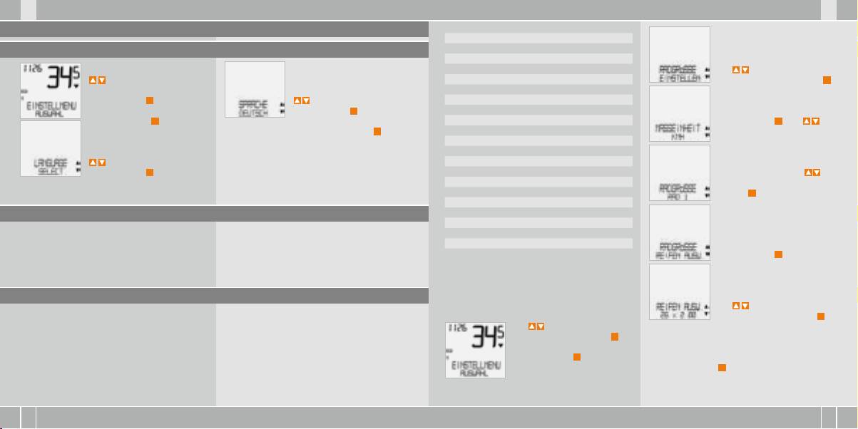
5. Grundeinstellungen
mm-Wert inch-Wert
16 x 1,75 1272 50,1
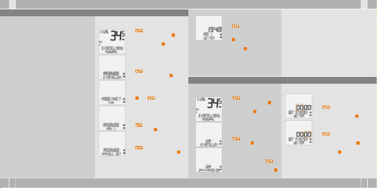
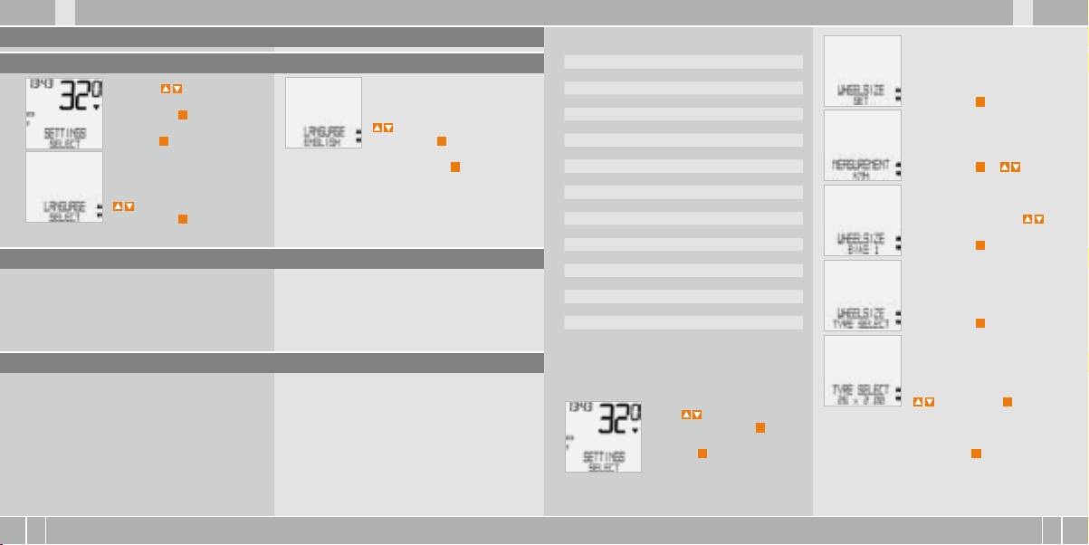
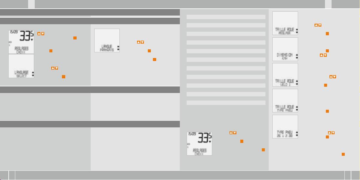
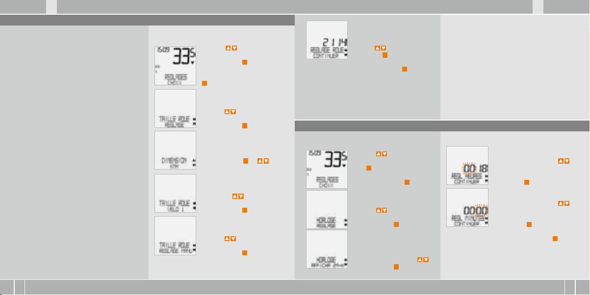
5.1 Sprache einstellen
20 x 1,75 1590 62,6
24 x 1 ⅜ 1948 76,7
Gehen Sie mit den
24 x 1,75 1907 75,1
Mit
zu RADGRÖSSE/
-Tasten zu
26 x 1 1973 77,7
EINSTELLEN. Bestätigen mit
M
.
EINSTELLMENU/AUSWAHL.
26 x 1,5 2026 79,8
Bestätigen mit
M
.
zu SPRACHE DEUTSCH.
26 x 1,6 2051 80,7
Sie befinden sich jetzt im Ein-
Bestätigen mit
M
.
26 x 1,75 2070 81,5
MASSEINHEIT/KMH.
stell-Modus (mit
C
– 3 Sekun-
26 x 1,9 2089 82,2
Bestätigen mit
M
oder
den kommen Sie zurück in den
DEUTSCH AUSWAHL OK? Bestätigen mit
M
.
26 x 2,00 2114 83,2
zum Wechsel zu MPH.
Funktions-Modus).
26 x 2,125 2133 84,0
Rückmeldung des Computers: SPRACHE AUSW
26 x 1 ⅜ 2105 82,9
zu LANGUAGE SELECT.
FERTIG. Der Computer kehrt automatisch zum
26 x ¾ 1954 76,9
Bestätigen mit
M
.
Ausgangsmenu EINSTELLMENU/AUSWAHL zurück.
27 x 1 ¼ 2199 86,6
RADGRÖSSE/RAD 1 (mit zur
28 x 1,5 2224 87,6
Einstellung für Rad 2). Bestäti-
28 x 1,75 2268 89,3
gen mit
M
.
28 x 1 ½ 2265 89,2
5.2 Einstellen und Messen der Radgröße
28 x 1 ⅜ 2205 86,8
30-622 2149 84,6
Damit Ihr VDO Computer korrekt messen kann,
32-622 2174 85,6
müssen Sie die Radgröße (Radabrollumfang) Ihres
37-622 2205 86,8
RADGRÖSSE/REIFEN AUSW.
Rades einstellen. Hier gibt es 2 Möglichkeiten:
40-622 2224 87,6
Bestätigen mit
M
.
5.2.1 Einstellen über Reifentabelle
So stellen Sie die Reifengröße über Auswahl
REIFEN AUSW./WÄHLEN.
des Reifens ein:
Mit wählen Sie jetzt Ihren
In der Reifentabelle sind die gängigen Reifentypen
Diese Werte weichen je nach Reifen-Marke,
Reifen aus. Bestätigen mit
M
.
aufgeführt. Wenn Ihr Reifentyp nicht aufgeführt
Reifenhöhe und Reifenprofil ab. Es kann daher
Mit zu EINSTELLMENU/
ist, empfehlen wir die manuelle Eingabe der Rad-
auch zu Abweichungen der gemessenen Strecke
AUSWAHL. Bestätigen mit
M
.
Es erscheint die Kontrollabfrage: „Reifengröße“/
größe. Die in der Tabelle genannten Werte sind
und der angezeigten Geschwindigkeit kommen.
Sie befinden sich jetzt im Ein-
AUSWAHL OK? Wenn die angezeigte Reifengröße
Näherungswerte.
stell-Modus (mit
C
– 3 Sekun-
mit der von Ihnen gewünschten übereinstimmt,
den kommen Sie zurück in den
bestätigen Sie mit
M
.
Funktions-Modus).
Das Display bestätigt RADGRÖSSE/SET FERTIG.
Automatische Rückkehr zu EINSTELLMENU/AUSWAHL.
D GB F I
X1 VDO CYCLECOMPUTING12
I F GB D
www.vdocyclecomputing.com X1 13
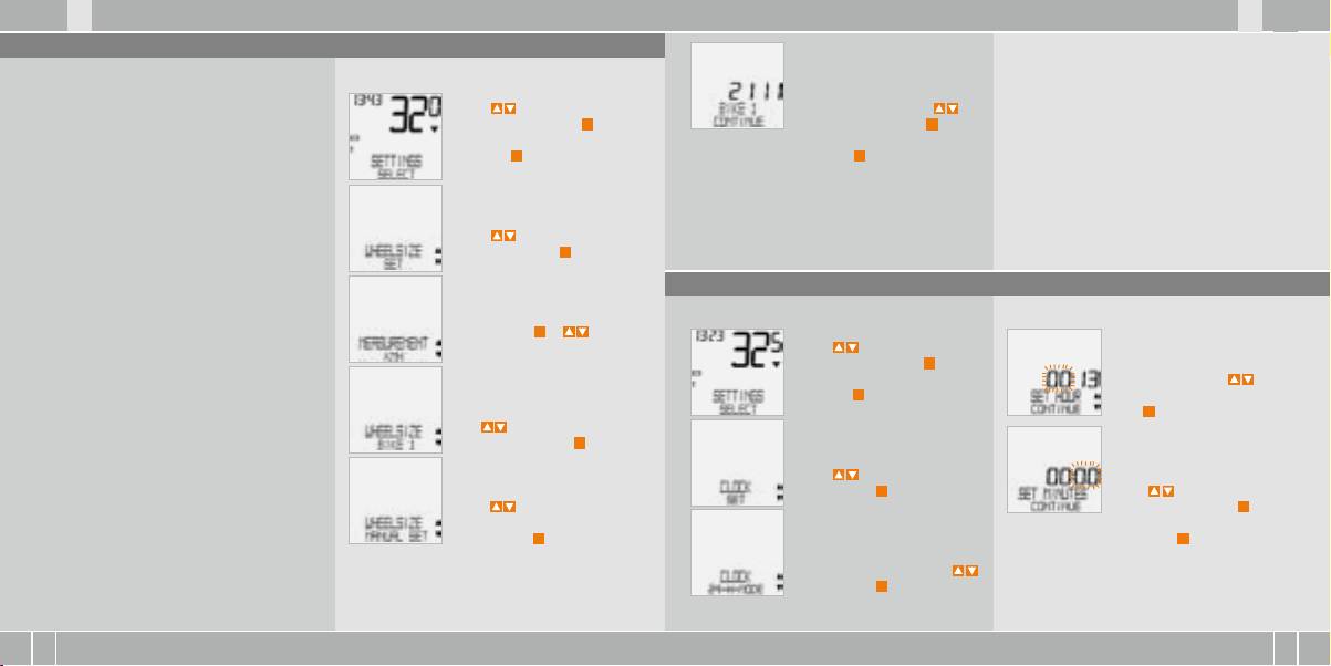
5.2.2 Einstellen über Radumfang >>> P05
Achtung: Die Werkseinstellungen betragen für
Für die manuelle Eingabe der Radgröße müssen Sie
So stellen Sie manuell die Radgröße ein:
RAD 1 …SET UMFANG/WEITER
Rad 1 = 2155 mm und für Rad 2 = 2000 mm. Wenn
zunächst den Radabrollumfang Ihres Rades messen.
Mit stellen Sie jetzt den
Sie keine Radgrößen eingeben, arbeitet der
Mit zu EINSTELLMENU/
gemessenen Radabrollumfang
Computer mit diesen Werkseinstellungen. Die so
Messen der Radabrollumfänge:
AUSWAHL. Bestätigen mit
M
.
ein. Bestätigen Sie die Eingabe
gemessenen Werte für Geschwindigkeit, Strecke
Sie befinden sich jetzt im
mit
M
.
etc. können deutlich von den tatsächlichen Werten
step 1 Ventil des Vorderrades genau senkrecht
Einstell-Modus (mit
C
–
abweichen.
zum Boden ausrichten.
3 Sekunden kommen Sie
RAD 1/SET OK? Bestätigen mit
M
.
zurück zum Funktions-Modus).
step 2 Diese Stelle am Boden mit einem Strich
Das Display bestätigt: RADGRÖSSE/SET FERTIG
(z.B. Kreide) markieren.
Automatische Rückkehr zu EINSTELLMENU/
AUSWAHL.
step 3 Das Rad eine Radumdrehung nach vorn
Mit zu RADGRÖSSE/EIN-
schieben, bis das Ventil erneut senkrecht zum
STELLEN. Bestätigen mit
M
.
Boden steht.
5.3 Einstellen Uhr
step 4 Diese Stelle ebenfalls am Boden markieren.
So stellen Sie die Uhr ein:
MASSEINHEIT/KMH. Bestätigen
step 5 Den Abstand zwischen den beiden Markie-
mit
M
oder zum Wechsel
Mit zu EINSTELLMENU/
rungen messen. Das ist Ihr Radumfang (=Abroll-
zu MPH.
AUSWAHL Bestätigen mit
M
.
UHR…SET STUNDEN/WEITER
Umfang).
Sie befinden sich jetzt im Ein-
Mit stellen Sie die Stun-
stell-Modus (mit
C
– 3 Sekun-
den ein. Bestätigen Sie die
step 6 Geben Sie den so gemessenen Radumfang
den kommen Sie zurück zum
Stundeneinstellung mit
M
.
in Ihren VDO-Computer ein.
RADGRÖSSE/ RAD 1
Funktions-Modus).
(mit zur Einstellung für Rad 2).
ACHTUNG: Wenn Sie KMH–Anzeige gewählt
Bestätigen mit
M
.
UHR…SET MINUTEN/WEITER
haben, müssen Sie den Radumfang in mm ein-
Mit stellen Sie die Minu-
geben (Bei gewählter MPH-Anzeige geben Sie
Mit zu UHR/EINSTELLEN
ten ein. Bestätigen Sie die
den Radumfang in inch ein).
Bestätigen mit
M
.
Minuten-Einstellung mit
M
.
Mit zu RADGRÖSSE/
MANUELL SET. Bestätigen mit
M
.
UHR/SET OK? Bestätigen Sie mit
M
.
UHR/24-H-ANZEIGE (mit
Das Display bestätigt: UHR SET FERTIG. Automati-
können Sie umstellen auf
sche Rückkehr zu EINSTELLMENU/AUSWAHL.
12-H-Anzeige). Bestätigen mit
M
.
D GB F I
X1 VDO CYCLECOMPUTING14
I F GB D
www.vdocyclecomputing.com X1 15
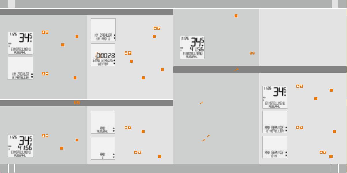
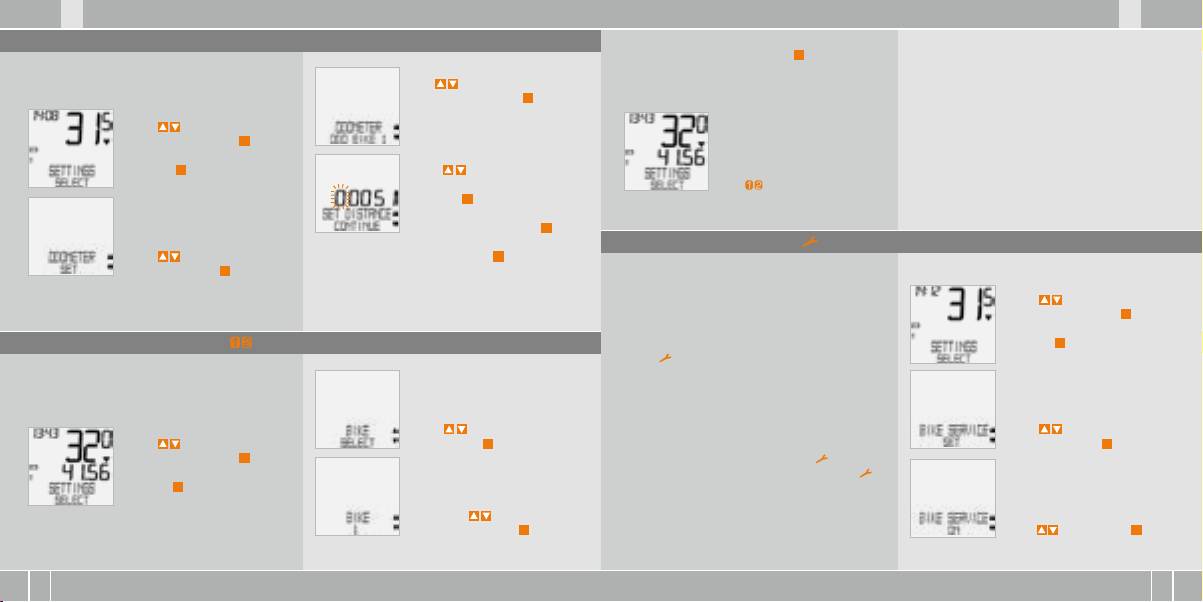
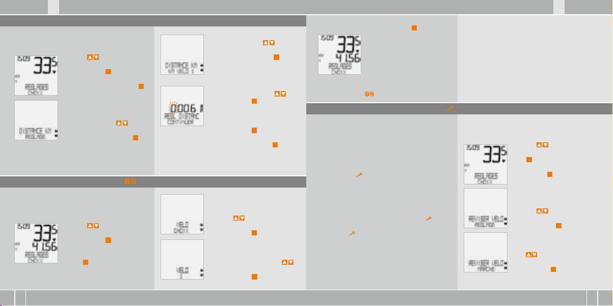
5.4 Einstellen Gesamtkilometer
RAD 1/AUSWAHL OK? Bestätigen mit
M
.
ACHTUNG, wichtiger Hinweis: Beim Wechsel von
Sie können die Werte der Streckenzähler jederzeit
Rad 1 auf 2 oder umgekehrt werden die Daten
(z.B. am Ende einer Saison) programmieren.
Das Display bestätigt RAD/AUSW FERTIG. Automati-
Tagestour, Fahrzeit, Durchschnittsgeschw. und
KM ZÄHLER/RAD 1 (mit
sche Rückkehr zu EINSTELLMENU/AUSWAHL
Max-Geschw. für die letzte Tour auf Null gestellt.
Mit zu EINSTELLMENU/
kommen Sie zur Einstellung für
AUSWAHL. Bestätigen mit
M
.
RAD 2). Bestätigen mit
M
.
Sie befinden sich jetzt im Ein-
stell-Modus (mit
C
– 3 Sekun-
KM RAD 1… EING STRECKE/WEITER
den kommen Sie zurück zum
Die blinkende Ziffer können Sie
Das ausgewählte Rad 1 oder 2
Funktions-Modus).
mit einstellen. Zum Aufruf
wird im Display unten links ( )
der nächsten Ziffer bestätigen
angezeigt.
Sie mit
M
. Wiederholen Sie die
Schritte, bis die letzte, rechte
Ziffer blinkt. Bestätigen mit
M
.
5.6 Service-Intervall-Anzeige
Mit zu KM ZÄHLER/EIN-
STELLEN. Bestätigen mit
M
.
KM RAD 1/SET OK? Bestätigen mit
M
.
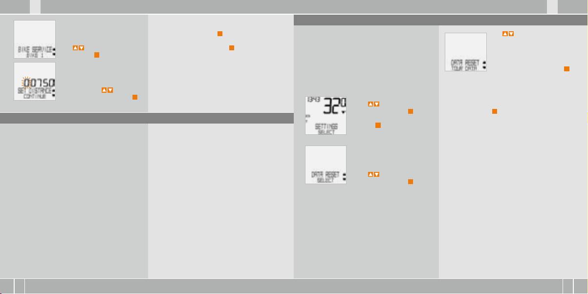
Die VDO Service-Intervall-Anzeige erinnert Sie daran,
So stellen Sie die Service-Intervalle ein:
Ihr Rad in der Werkstatt überprüfen zu lassen.
Das Display bestätigt KM RAD 1 /SET FERTIG.
Sie können das Service-Intervall EIN- oder AUS-
Mit zu EINSTELLMENU/
Automatische Rückkehr zu EINSTELLMENU/
schalten. Sie können individuelle Service-Intervalle
AUSWAHL. Bestätigen mit
M
.
AUSWAHL.
für 2 Räder einstellen. Wenn die eingestellte
Sie befinden sich jetzt im Ein-
Service-Intervall-Strecke gefahren wurde:
stell-Modus (mit
C
– 3 Sekunden
5.5 Umschalten von Rad 1 auf Rad 2
B
Blinkt das -Symbol im Display auf.
kommen Sie zurück zum Funk-
B
In der Informationszeile erscheint
tions-Modus).
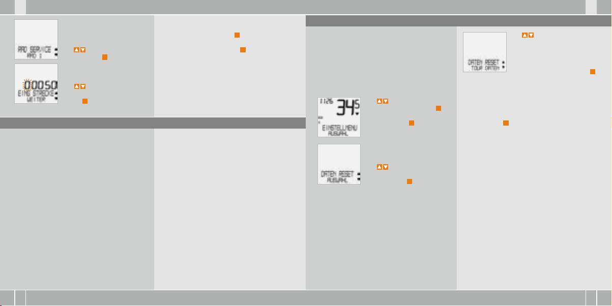
RAD SERVICE/RAD 1
Ihr VDO Computer kann an 2 Fahrrädern verwen-
Jetzt sollten Sie den empfohlenen Radcheck ent-
det werden. Wenn Sie von Rad 1 auf Rad 2 wech-
weder selbst durchführen oder Ihr Rad vom Fach-
seln, müssen Sie den Computer vor der Fahrt auf
händler checken lassen.
das benutzte Rad einstellen:
Mit zu RAD / AUSWAHL.
Drücken Sie eine beliebige Taste. Der Text RAD SER-
Mit zu RADSERVICE/
Bestätigen mit
M
.
VICE verschwindet wieder. Nach weiteren 50 km
EINSTELLEN. Bestätigen mit
M
.
Mit zu EINSTELLMENU/
erlischt auch das -Symbol wieder. Sie können
AUSWAHL. Bestätigen mit
M
.
das blinkende -Symbol auch abschalten. Geben
Sie befinden sich jetzt im Ein-
Sie dazu das Service-Intervall erneut ein.
stell-Modus (mit
C
– 3 Sekunden
kommen Sie zurück zum Funk-
RAD 1 (mit stellen Sie um
RADSERVICE/EIN (mit schalten
tions-Modus).
auf RAD 2). Bestätigen mit
M
.
Sie auf AUS). Bestätigen mit
M
.
D GB F I
X1 VDO CYCLECOMPUTING16
I F GB D
www.vdocyclecomputing.com X1 17
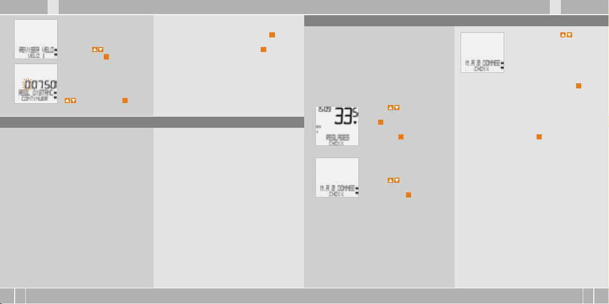
5.8 Reset-Funktionen
Wiederholen Sie die Schritte, bis die letzte, rechte
Ziffer blinkt. Bestätigen mit
M
.
Mit der RESET Funktion stellen Sie wahlweise zurück
Mit zu den Daten, die Sie
RAD SERVICE/RAD 1.
B
TOUR DATEN
zurückstellen wollen:
Mit wechseln Sie zu RAD 2.
RAD 1/SET OK? Bestätigen mit
M
.
B
TOTAL KM
B
DATEN RESET/TOUR DATEN
Bestätigen mit
M
.
Bei den jeweiligen Reset-Modi werden folgende
ODER
Das Display bestätigt: RADSERVICE/SET FERTIG.
Informationen gelöscht:
B
TOTAL KM
RAD 1…EING STRECKE.
Automatische Rückkehr zu EINSTELLMENU/
B
TOUR DATEN: Tagestour, Fahrzeit,
Bestätigen Sie Ihre Auswahl mit
M
.
Die blinkende Ziffer können Sie
AUSWAHL.
Durchschnitts geschw., Max-Geschw.
mit einstellen. Zum Aufruf
B
TOTAL KM: Gesamt km, km Rad 1, km Rad 2
Abfrage. AUSWAHL/RESET?
der nächsten Ziffer bestätigen
Sie mit
M
.
Mit
zu EINSTELLMENU/
ACHTUNG: Dieser Schritt kann nicht rückgängig
AUSWAHL. Bestätigen mit
M
.
gemacht werden.
Sie befinden sich jetzt im Ein-
5.7 Sleep-Modus
stell-Modus (mit
C
– 3 Sekunden
Bestätigen mit
M
, nur wenn Sie die ausgewählten
kommen Sie zurück zum Funk-
Daten löschen wollen. Das Display bestätigt:
Ihr VDO-Computer ist mit einer Sleep-Modus
Der Sleep-Modus (Uhr wird angezeigt) schaltet
tions-Modus).
DATEN RESET/RESET FERTIG. Automatische Rück-
Funktion ausgestattet. Im Sleep-Modus wird ein
sich ein, wenn 5 min. lang keine Geschwindigkeits-
kehr zu EINSTELLMENU/AUSWAHL.
Großteil des Displays ausgeschaltet, um Batterie-
impulse verarbeitet werden und keine Taste betä-
leistung zu sparen. Uhrzeit und Service-Intervall
tigt wurde.
Anzeige werden weiter angezeigt.
Mit zu
Der Sleep-Modus wird beendet, wenn wieder Ge-
DATEN RESET/AUSWAHL.
schwindigkeitsimpulse verarbeitet werden (beim
Bestätigen mit
M
.
Fahren) oder eine Taste betätigt wird.

D GB F I
X1 VDO CYCLECOMPUTING18
I F GB D
www.vdocyclecomputing.com X1 19
6. Garantiebedingungen
Gesamt-KM 1 u. 2 Messbereich:
Radumfang Einstellbereich:
VDO Cycle Parts gewährt für Ihren VDO-Computer
Bitte wenden Sie sich mit allen Reklamationen
bis 99.999 km oder mi
von 100 mm bis 3999 mm (3,9 bis 157,4 inch)
eine Garantie von 5 Jahren ab Kaufdatum. Die
und Garantieansprüchen an Ihren Fachhändler,
Total Kilometer Messbereich:
Garantie erstreckt sich auf Material- und Verar-
bei dem Sie das Gerät gekauft haben. Oder senden
bis 199.999 km or mi
beitungsfehler am Computer selbst, am Sensor/
Sie Ihre Reklamation direkt an:
Sender und an der Lenkerhalterung. Kabel und
Batterien sowie Montagematerialien sind von
Cycle Parts GmbH
8. Fehlerbehebung
der Garantie ausgeschlossen. Die Garantie ist
Große Ahlmühle 33
nur dann gültig, wenn die betroffenen Teile nicht
D-76865 Rohrbach (Germany)
geöffnet wurden (Ausnahme: Batteriefach des
Hier finden Sie eine Liste möglicher Fehler, ihrer Ursachen und was Sie dagegen tun können:
Computers), keine Gewalt angewendet wurde und
Für technische Fragen stehen wir Ihnen jederzeit
keine mutwillige Beschädigung vorliegt.
unter folgender Hotline zur Verfügung:
Fehler Mögliche Ursache Behebung
Bitte bewahren Sie den Kaufbeleg sorgfältig auf,
+49 (0) 63 49 - 96 35 - 10.
da er im Reklamationsfall vorgelegt werden muss.
Halbe Segmente in der Anzeige
Computer-Software läuft nach
Batterie herausnehmen
Bei einer berechtigten Reklamation erhalten Sie
Weitere technischen Informationen erhalten Sie
(z.B. nach einem Batteriewechsel)
Batteriewechsel nicht korrekt
und neu einsetzen
von uns ein vergleichbares Austauschgerät. Ein
unter: www.vdocyclecomputing.com
Anspruch auf Ersatz des identischen Modells
Keine Geschwindigkeits-Anzeige Abstand von Sensor zu Magnet
Position von Sensor und
besteht nicht, wenn durch Modellwechsel die
Im Zuge der Weiterentwicklung behalten wir uns
zu groß
Magnet korrigieren
Produktion des reklamierten Modells eingestellt
technische Änderungen vor.
wurde.
Keine Geschwindigkeits-Anzeige Computerkopf nicht korrekt
Computerkopf in die Lenker-
in der Lenkerhalterung
halterung setzen, bis zum
eingerastet
Anschlag („click“) drehen
7. Technische Spezifikationen
Keine Geschwindigkeits-Anzeige Radumfang ist nicht korrekt
Radumfang einstellen
eingestellt oder steht auf Null
Computer:
Arbeits-Temperatur des Displays:
ca. 45 x 52 x 16 mm, Gewicht: ca. 45 g
-15 °C to +60 °C
Anzeige wird schwach Batterie leer Batterie prüfen, evtl. ersetzen
Lenkerhalterung:
Geschwindigkeits-Bereich:
Gewicht: ca. 15 g
bei Radgröße 2155 mm, min 2.5 km/h,
Anzeige wird schwach Temperaturen unter 5° machen
Bei normalen Temperaturen
Sensor: Gewicht ca. 20 g
max 199.5 km/h
die Anzeige träge
arbeitet die Anzeige wieder
Batterie Computer:
Fahrzeit Messbereich:
normal
3V, Type 2032
bis 23:59:59 HH:MM:SS
Batterie Lebensdauer:
Tagestour-Zähler Messbereich:
1200 Fahr-Stunden, ca.. 24.000 km (15.000 M)
bis 999,99 km oder mi

F I
X1 VDO CYCLECOMPUTING20
I F
www.vdocyclecomputing.com X1 21
DGBD GB
Preface
Table of contents
Congratulations
1. Display 22
5. Basic settings 28
With your selection of a VDO computer you have opted for a technically very high quality appliance.
5.1 Setting the language 28
In order to fully benefit from the potential of the computer, we recommend that you carefully read this
2. Operation 24
5.2 Setting and measuring the wheel size 28
manual. It contains all operating instructions and many other useful tips.
5.2.1 Select from tyre table 28
3. Information functions 25
5.2.2 Setting using wheel circumference 30
We hope you enjoy cycling with your VDO bike computer.
5.3 Setting the CLOCK 31
Cycle Parts GmbH
4. Installation 26
5.4 Setting the total kilometres 32
4.1 Fitting the sensor, magnet
5.5 Switch from Bike1 to Bike2 32
and handlebar holder 26
5.6 Service interval display
33
4.2 Installing the battery in the computer 27
5.7 Sleep mode 34
Pack contents
4.3 Placing the computer into
5.8 Reset functions 35
the handlebar holder 27
Please first check that this pack is complete:
6. Terms of guarantee 36
1 VDO computer
1 universal handlebar holder
7. Technical spezifications 36
Battery installed
with cable and sensor
8. Troubleshooting 37
1 rubber pad
1 spoke magnet
cable ties
„>>> P02“ links at the beginning of a chapter
for sensor
(clip magnet)
for fitting the holder
and sensor
are related to the respective picture in the
picture book!
F I
X1 VDO CYCLECOMPUTING22
I F
www.vdocyclecomputing.com X1 23
DGBD GB
1. Display
Service indicator
Speed difference indicator (current)
The display can be divided
shows that your bike should go for a service.
to speed (average)
into 4 sections:
You can set the service interval individually for
The computer compares the current speed
bike 1 and bike 2
with the average speed.
Section 1
Section 2
The indicator shows
always shows
shows the
Indicator bike 1/bike 2
B
whether the current speed is higher than
the current time.
current speed.
The computer can work with two different set-
the average (+1 KMH)
tings for 2 bikes. The indicator shows which of the
B
below the average (-1 KMH)
two bikes you have chosen to use.
B
or matches the average
You will also find
Section 3
The total distances are accordingly counted and
(tolerance +/- 1 KMH).
indicator elements
shows the value of the
stored separately for bike 1 and bike 2.
on the display
display function/
Menu prompt indicator
You can find the description
information that you
Measurement unit (KMH or MPH)
When a submenu has been accessed, these indi-
of the individual indicators on
selected.
The computer can display both KHM and MPH.
cators flash and show that there are other selec-
the right hand side.
Distances are shown in kilometres or miles
tion options or that the computer is waiting for
Section 4
accordingly.The indicator shows the selected
an entry (setting mode).
shows the description of
measurement unit
the selected function in
the top line (info line). The
second line (menu line)
shows,
B
whether there is more
information „MORE“
B
whether there is
another selection
option „SELECT“
F I
X1 VDO CYCLECOMPUTING24
I F
www.vdocyclecomputing.com X1 25
DGBD GB
2. Operation
3. Information functions in function mode
To make your computer easy to use, we have devel-
Menu indicators on the display flash to show that
TRIPDISTANCE
RIDE TIME
oped the EMC Easy Menu Control system.
there are other selection options.
Shows the distance of the current trip since the
Shows the ride time of the current day‘s trip since
The EMC makes your computer easier to operate
In function mode and setting mode, the computer is
last reset.Maximum value 999.99 km.
the last reset. Maximum 23:59:59 HH:MM:SS
by means of a full text menu guidance,
operated using the 4 buttons.
If the maximum value is exceeded, the counter
If the maximum value is exceeded, the ride time
as is used on most mobile phones.
starts again at zero. At the same time the values for
measurement starts again at zero. At the same
ride time and average speed are set back to zero
time the day‘s tripdistance and average speed are
set back to zero.
TRIPDISTANCE/MORE
MORE shows that there is a submenu for the main
AVG SPEED
menu TRIPDISTANCE. You open the submenu with
Shows the average speed, calculated from the
C = CLEAR
M = MENU
the
M
button. In the submenu you will find:
day‘s tripdistance and ride time, since the last reset
DOWN
UP
B
Total kilometres BIKE 1 ODO BIKE 1 up to a
Accuracy: 2 decimal places.
maximum of 99,999 km.
The average speed is recalculated if the day‘s trip-
B
Total kilometres BIKE 2 ODO BIKE 2 up to a
distance or ride time exceeds the maximum value.
C
FUNCTION 3
= CLEAR
M
= MENU
maximum of 99,999 km.
In function mode:
FUNCTION 4
In function mode:
B
Total kilometres for Bike 1 + Bike 2 ODO TOTAL
MAX SPEED
B
Jump back a menu level from
B
Access available submenu.
up to a maximum of 199,999 km.
Shows the maximum speed on the current trip since
FUNCTION 5
the submenu.
B
Confirm selection.
You leave the submenu by pressing
C
again.
the last reset. Accuracy: 2 decimal places.
FUNCTION 6
In setting mode:
You can recognise a submenu by
B
Jump back to function mode.
the flashing menu indicators.
B
Correct an entry.
In setting mode:
B
Jump back a digit.
B
Select a setting.
B
Confirm a setting.
= DOWN
B
Confirm a selection made.
In function mode:
B
Scroll downwards within
= UP
the functions.
In function mode:
In setting mode:
B
Scroll upwards within
B
Scroll downwards within
the functions
the setting modes.
In setting mode:
B
Decrease a digit.
B
Scroll upwards within
the setting modes.
B
Increase a digit.

F I
X1 VDO CYCLECOMPUTING26
I F
www.vdocyclecomputing.com X1 27
DGBD GB
4 Installation
4.2 Installing the battery in the computer >>> P03
4.1 Fitting the sensor, magnet and handlebar holder >>> P01
Your VDO computer is supplied with a 3V battery
TIP for changing battery: VDO recommends chang-
(type 2032). The battery is already installed
ing the battery once a year. Buy a new battery in
When fitting to suspension forks, it is essential
Step 4 Install cable from sensor already fitted
when supplied. To change the battery, proceed
good time to ensure the function works perfectly.
to bear in mind the spring deflection of the
along brake cable to the handlebars (fasten with
as follows:
When the battery is changed, all basic compu-
forks. The cable requires an appropriate amount
cable ties supplied) Ideally: Coil sensor cable up
ter settings are reset to factory settings. Before
of play.
around the brake cable.
step 1 Place the battery in the computer casing
removing the old battery, it is therefore essential
with the +terminal facing up.
to note down the wheel sizes entered and the
ATTENTION: Risk of broken cable.
Step 5 Decide whether fitting to handlebar or
total kilometres cycled so far for your bike 1 and
stem and turn the base of the handlebar holder
Step 2 Make sure that the battery does not
bike 2. Program these in again after inserting the
Step 1 Place the rubber pad under the sensor.
by 90° accordingly. To do so, undo the screws in
get wedged.
new battery.
Fit the sensor on the same side of the fork where
the holder, take out the foot and turn it 90°, in-
you later want to fit the computer to the handle-
sert and tighten the screws again.
step 3 Take care that the rubber seal lies flat on
bars (right or left) using the cable ties supplied
the battery compartment lid.
(loose at first, do not pull tight just yet).
ATTENTION: Do not over tighten screws.
Depending on the room available, the sensor can
Step 4 Insert the battery compartment lid into the
be fitted at the front of the fork, inner side of the
Step 6 Guide the cable ties through the slot in
opening and turn it with a coin to the right as far
fork or backside of the forks. >>> P02
the handlebar holder, place around the handle
as it will go (approx. 1/3 turn).
bars or the stem and pull (do not pull tight just
Step 2 Place spoke magnet around an outer
yet).
spoke. The silver middle of the magnet points
towards the sensor. Align the magnet to the
Step 7 If fitting to handlebars: Align computer
sensor mark with a gap of about 1 - 5 mm.
angle to achieve optimum readability. Now pull
4.4 Placing the computer into the handlebar holder >>> P04
cable ties tight. Snip off protruding ends with
Step 3 Align sensor and magnet for good and
clippers.
The VDO twist-click system fastens the computer
Step 3 To take the computer out, twist to the left
fasten in place: Pull cable ties tight and push
securely with the handlebar holder.
(do not push or pull).
magnet in firmly.
Step 1 Place computer into the holder in 10 o’clock
How to remember: Rigid to the Right, Loose to the Left
position.
Step 2 Twist computer to the right to 12 o’clock posi-
tion and click into the holder system.
X1 VDO CYCLECOMPUTING28
www.vdocyclecomputing.com X1 29
I F DGBD GB IF
5. Basic settings
mm-value inch-value
5.1 Setting the language
16 x 1,75 1272 50,1
20 x 1,75 1590 62,6
Using up/down go to
Using the buttons, go to
24 x 1 ⅜ 1948 76,7
WHEELSIZE/SET.
SETTINGS/SELECT.
24 x 1,75 1907 75,1
Confirm with
M
.
Confirm with
M
.
26 x 1 1973 77,7
You are now in setting mode
to LANGUAGE ENGLISH.
26 x 1,5 2026 79,8
(pressing
C
for 3 seconds gets
Confirm with
M
.
26 x 1,6 2051 80,7
you back to function mode).
26 x 1,75 2070 81,5
MEASUREMENT/KMH.
ENGLISH SELECT OK? Confirm with
M
.
26 x 1,9 2089 82,2
Confirm with
M
or to
26 x 2,00 2114 83,2
change to MPH.
LANGUAGE SELECT DONE. The computer automati-
26 x 2,125 2133 84,0
to LANGUAGE SELECT.
cally returns to the start menu SETTINGS/SELECT.
26 x 1 ⅜ 2105 82,9
Confirm with
M
.
26 x ¾ 1954 76,9
WHEELSIZE/BIKE 1 (use to
27 x 1 ¼ 2199 86,6
go to setting for bike 2).
28 x 1,5 2224 87,6
Confirm with
M
.
5.2 Setting and measuring the wheel size
28 x 1,75 2268 89,3
28 x 1 ½ 2265 89,2
You must set the wheel size (wheel roll circum-
There are 2 ways of doing this:
28 x 1 ⅜ 2205 86,8
ference) of your bike so that your VDO computer
30-622 2149 84,6
can measure correctly.
32-622 2174 85,6
WHEELSIZE/ TYRE SELECT.
37-622 2205 86,8
Confirm with
M
.
40-622 2224 87,6
5.2.1 Setting using tyre table
How to set the tyre size by selecting the tyre:
TYRE SELECT/SELECT.
The common types of tyres are listed in the tyre
The values given in the table are approximate
Now select your tyres using
table. If your tyre type is not listed, we recommend
values. These values differ according to brand, tyre
. Confirm with
M
.
entering the wheel size manually.
height and tyre profile. This can consequently also
Using go to SETTINGS/
lead to discrepancies in the distance measured
SELECT. Confirm with
M
.
The confirmation question appears “Tyresize“/
and the speed shown.
You are now in setting mode
SELECT OK? When the displayed tyre size matches
(pressing
C
for 3 seconds gets
the one you want, confirm with
M
.
you back to function mode).
The display confirms WHEELSIZE/SET DONE
Automatic return to SETTINGS/SELECT.
F I
X1 VDO CYCLECOMPUTING30
I F
www.vdocyclecomputing.com X1 31
DGBD GB
5.2.2 Setting using wheel circumference >>> P05
ATTENTION: The factory settings for bike 1 = 2155 mm
To enter the wheel size manually, you must first
How to set the wheel size manually:
BIKE 1 ...SET SIZE/CONTINUE
and for bike 2 = 2000 mm. If you do not enter any
measure the wheel roll circumference on your bike.
Now set the wheel roll circum-
wheel sizes, the computer works with these fac-
Using go to SETTINGS/
ference measured using .
tory settings. The values measured in this way
Measuring wheel roll circumferences:
SELECT. Confirm with
M
Confirm the entry with
M
.
for speed, distance etc. can differ widely from
You are now in setting mode
the actual values.
step 1 Precisely align valve on the front wheel
(pressing
C
for 3 seconds gets
BIKE 1/SET OK? Confirm with
M
.
vertically to the ground.
you back to function mode)
The display confirms: WHEELSIZE/SET DONE.
Step 2 Mark this spot on the ground with a line
Automatic return to SETTINGS/SELECT.
(e.g. chalk).
Using go to WHEELSIZE/
step 3 Push the bike forwards one turn of the
SET. Confirm with
M
.
wheel until the valve is vertical to the ground
again.
5.3 Setting the clock
Step 4 Also mark this spot on the ground.
MEASUREMENT/KMH.
How to set the clock:
Confirm with
M
or to
Step 5 Measure the distance between the two
change to MPH.
Using go to SETTINGS/
marks.That is your wheel circumference
SELECT. Confirm with
M
.
CLOCK...SET HOUR/CONTINUE
(=roll circumference).
You are now in setting mode
Set the hours using .
(pressing
C
for 3 seconds gets
Confirm the hour setting
Step 6 Enter the wheel circumference measured
WHEELSIZE/BIKE 1.
you back to function mode)
with
M
.
in this way into your VDO computer.
(use to go to setting for
bike 2) Confirm with
M
.
ATTENTION: If you have selected KMH display,
CLOCK...SET MINUTES/
you must enter the wheel circumference in mm
Using go to CLOCK/SET.
CONTINUE. Set the minutes
(If MPH display is selected, enter the wheel
Confirm with
M
.
using . Confirm the
circumference in inches).
Using go to
minutes setting with
M
.
WHEEL-SIZE/MANUAL SET.
Confirm with
M
.
CLOCK/SET OK? Confirm with
M
.
CLOCK/24-H-MODE (you can
switch to 12-H mode using .
The display confirms: CLOCK/SET DONE.
Confirm with
M
.
Automatic return to SETTINGS/SELECT.
F I
X1 VDO CYCLECOMPUTING32
I F
www.vdocyclecomputing.com X1 33
DGBD GB
5.4 Setting the total kilometres
BIKE 1 /SELECT OK? Confirm with
M
.
ATTENTION, important note: When switching
You can program the values on the distance coun-
ODOMETER/ODO BIKE 1
from bike 1 to 2 or vice versa, the data for day‘s
ter at any time (e.g. at the end of a season).
(use to go to setting for
The display confirms BIKE/SELECT DONE
tripdistance, ride time, average speed and max.
BIKE 2). Confirm with
M
.
Automatic return to SETTINGS/SELECT
speed for the last trip are set to zero.
ODO BIKE 1 ...SET DISTANCE/
Using go to SETTINGS/
CONTINUE.
SELECT. Confirm with
M
.
You are now in setting mode
You can set the flashing digits
The selected bike 1 or 2) is
(pressing
C
for 3 seconds gets
using .
shown on the display bottom
you back to function mode).
To access the next digit, con-
left. ( )
firm with
M
. Repeat the steps
until the last digit on the right
is flashing. Confirm with
M
.
5.6 Service interval display
Using go to ODOMETER/
ODO BIKE 1/SET OK? Confirm with
M
.
SET. Confirm with
M
.
The VDO service interval display reminds you to
How to set the service interval:
The display confirms ODO BIKE 1/SET DONE.
have your bike checked in the workshop.
Automatic return to SETTINGS/SELECT.
You can switch the service interval ON or OFF.
Using go to SETTINGS/
You can set separate service intervals for 2 bikes
SELECT. Confirm with
M
.
When the set service interval distance has been
You are now in setting mode
5.5 Switch from Bike 1 to Bike 2
reached:
(pressing
C
for 3 seconds gets
B
The -symbol flashes on the display.
you back to function mode).
B
The information line displays
Your VDO computer can be used on two bikes.
BIKE SERVICE/BIKE 1
If you switch from bike 1 to bike 2, you must set the
You should now either carry out the recommend-
computer to the bike being used before the ride.
ed bike check yourself or have the bike checked
Using go to BIKE/SELECT
by your dealer.
Using go to BIKE SERVICE/
Using go to SETTINGS/
Confirm with
M
.
Press any button. The text BIKE SERVICE disap-
SET. Confirm with
M
.
SELECT. Confirm with
M
.
pears again. After another 50 km the -also dis-
You are now in setting mode
appears. You can also switch off the flashing
(pressing
C
for 3 seconds gets
symbol. To do so, enter the service interval again.
you back to function mode).
BIKE 1 (use to switch to
BIKE SERVICE/ON (switch to OFF
bike 2). Confirm with
M
.
using ). Confirm with
M
.
F I
X1 VDO CYCLECOMPUTING34
I F GB D
www.vdocyclecomputing.com X1 35
DGBFID GB
5.8 Reset functions
Repeat the steps until the last digit on the right
is flashing. Confirm with
M
.
You use the RESET function to set any of these back
Use to go to the data you
BIKE SERVICE/BIKE 1
B
TOUR DATA
want to reset:
(use to switch to bike 2)
BIKE 1/SET OK? Confirm with
M
.
B
ODO TOTAL
B
DATA RESET/TOUR DATA
Confirm with
M
.
With the respective reset modes, the following
OR
The display confirms: BIKE SERVICE/SET DONE.
information is deleted:
B
DATA RESET/ODO TOTAL
Automatic return to SETTINGS/SELECT.
B
TOUR DATA: Day‘s tripdistance, ride time,
Confirm your selection with
M
.
BIKE 1 ...SET DISTANCE/
average speed, max. speed
CONTINUE. You can set the flash-
B
ODO TOTAL: Total km, km bike 1, km bike 2
Query: SELECTED DATA/RESET?
ing digits using To access
the next digit, confirm with
M
.
ATTENTION: This step cannot be reversed.
Using go to SETTINGS/
SELECT. Confirm with
M
.
Only confirm with
M
, if you want to delete the
5.7 Sleep mode
You are now in setting mode
selected data. The display confirms:
(pressing
C
for 3 seconds gets
DATA RESET/RESET DONE.
Your VDO computer is equipped with a sleep
Sleep mode switches itself on after 5 minutes if
you back to function mode).
Automatic return to SETTINGS/SELECT.
mode function.
no speed impulses are processed and no button
In sleep mode, a large part of the display is switched
is pressed.
off to save battery power. Time and service
interval display continue to be displayed.
Sleep mode is ended when speed impulses are
processed again (when cycling) or a button is
pressed.
Using go to DATA RESET/
SELECT. Confirm with
M
.

D GB F I
X1 VDO CYCLECOMPUTING36
I F GB D
www.vdocyclecomputing.com X1 37
GB DGBD
6. Terms of guarantee
Total KM 1 and 2 measurement range:
Wheel circumference setting range:
VDO Cycle Parts grants a guarantee of 5 years
Please contact the dealer from whom you
up to 99,999 km or mi
from 100 mm to 3999 mm
from the date of purchase for your VDO computer.
purchased the device for all complaints and
Total kilometers measurement range:
(3.9 to 157.4 inches)
The guarantee covers material and processing de-
guarantee claims. Or send your complaint
up to 199,999 km or mi
fects on the computer itself, on the sensor/trans-
directly to:
mitter and on the handlebar holder. Cables and
batteries as well as assembly materials are excluded
Cycle Parts GmbH
from the guarantee. The guarantee is only valid
Große Ahlmühle 33
8. Troubleshooting
if the parts concerned have not been opened
D-76865 Rohrbach (Germany)
(exception: battery compartment on the compu-
Here you can find a list of possible faults, their causes and what you can do about them:
ter), no force has been used and there is
We would be pleased to answer any technical
no sign of wilful damage.
questions you might have at the following
Error Possible cause Correction
Please take care to keep the receipt as it must
hotline number:
be presented in the event of a complaint.
+49 (0) 63 49 - 96 35 - 10.
Half segments on the display
Computer software not running
Take out battery and insert
If the complaint is justified, you will receive a
(e.g. after a battery change)
correctly after battery change
again
comparable replacement appliance from us.
Additional technical information is available at:
You are not entitled to an identical replacement
www.vdocyclecomputing.com
No speed display Distance from sensor to
Correct position of sensor
model if the model in question is no longer in
magnet too big
and magnet
production due to a change of model.
We reserve the right to make technical changes in
the course of further development.
No speed display Computer not properly clicked
Place computer head in the
in the handlebar holder
handlebar holder, twist until
it clicks
7. Technical spezifications
No speed display Wheel circumference is not
Set wheel circumference
correctly set or is at zero
Computer:
Working temperature of the display:
approx. 45 x 52 x 16 mm, weight: approx. 45 g
-15 °C to +60 °C
Display becomes weak Battery dead Check battery, replace if nec.
Handlebar holder:
Speed range:
weight: approx. 15 g
for wheel size 2155 mm, min 2.5 km/h,
Display becomes weak Temperatures under 5° make
At normal temperatures the
Sensor:
max 199.5 km/h
the display sluggish
display will work normally
weight approx. 20 g
Ride time measurement range:
again
Computer battery:
up to 23:59:59 HH:MM:SS
3V, type 2032
Day‘s trip counter measurement range:
Battery life-span:
up to 999.99 km or mi
1200 cycling hours, approx. 24,000 km (15.000 M)

D GB F I
X1 VDO CYCLECOMPUTING38
I F GB D
www.vdocyclecomputing.com X1 39
Préface
Sommaire
Merci !
1. Ecran 40
5. Réglages de base 46
En choisissant un compteur VDO, vous avez choisi un appareil aux qualités techniques élevées. Nous
5.1 Régler la langue 46
vous recommandons de lire attentivement la présente notice d‘utilisation de manière à utiliser au
2. Utilisation 41
5.2 Régler et mesurer la taille de la roue 46
mieux le potentiel de votre compteur. Celle-ci vous fournira toutes les informations nécessaires pour
5.2.1 Sélection dans le tableau de gonflage
l‘utilisation de votre compteur, ainsi que d‘autres astuces utiles.
3. Fonctions d’information en mode 43
des pneumatiques 46
de fonctionnement
5.2.2 Réglage au moyen de
Nous vous souhaitons beaucoup de plaisir lors de toutes vos sorties avec votre compteur Cycle VDO.
la circonférence de la roue 48
Cycle Parts GmbH
4. Installation 44
5.3 Régler l’heure 49
4.1 Montage du capteur, de l’aimant
5.4 Régler le kilométrage total 50
et du support pour guidon 44
5.5 Commutation VELO 1 / VELO 2 50
Contenu de l‘emballage
4.2 Mise en place de la pile
5.6 Affichage des intervalles de service 51
dans le compteur 45
5.7 Mode « Veille » 52
Veuillez tout d‘abord vérifier si l‘emballage contient toutes les pièces requises :
4.3 Mise en place du compteur dans
5.8 Fonction de mise à zéro 53
le support du guidon 45
1 compteur VDO
1 support universel pour guidon
Batterie mise en place
avec câble et capteur
6. Conditions de garantie 54
7. Caractéristiques techniques 54
8. Diagnostic de pannes 55
1 rondelle en caoutchouc
1 aimant pour rayon
ligatures de câbles
pour capteur
(aimant à clipser)
pour le montage du support,
du capteur et du câble
„>>> P02“ au début d’un chapitre renvoie
à la photo concernée dans le livret de photos !
D GB F I
X1 VDO CYCLECOMPUTING40
I F GB D
www.vdocyclecomputing.com X1 41
1. Ecran
Indicateur de service
Indicateur de différence entre la vitesse
L’écran peut être subdivisé en 4 zones :
Indique que votre vélo devrait être révisé.
(actuelle) et la vitesse (moyenne)
L’intervalle de service peut être déterminé indi-
Le compteur compare la vitesse actuelle
viduellement pour la roue 1 et la roue 2.
avec la vitesse moyenne.
La zone 1
La zone 2
L’indicateur indique
indique toujours
indique la vitesse
Indicateur Vélo 1 / Vélo 2
B
si la vitesse actuelle est supérieure
l’heure actuelle.
actuelle.
Le compteur peut être utilisé avec deux réglages
à la moyenne (+ 1 KMH),
différents, pour 2 vélos. L’indicateur indique quel
B
si la vitesse actuelle est inférieure
vélo a été sélectionné. Les kilométrages totaux
à la moyenne (- 1 KMH),
La zone 3
sont comptabilisés et enregistrées indépendam-
B
ou si la vitesse actuelle correspond
L’écran indique également
indique la valeur pour
ment pour le vélo 1 et le vélo 2.
à la moyenne (tolérance de +/- 1 KMH).
des éléments d’indication.
la fonction / l’information
La description des différents
sélectionnée.
Unité de mesure (KMH ou MPH)
Indicateur de commande du menu
indicateurs se trouve sur
Le compteur peut travailler soit en KMH, soit en
Lorsqu’un sous-menu est appelé, ces indicateurs
la page de droite.
MPH. Les distances s’affichent alors en kilomètres
clignotent et indiquent que d’autres possibilités
La zone 4
ou en milles. L’indicateur indique l’unité de mesu-
de sélection existent ou que le compteur attend
indique, dans la ligne
re sélectionnée.
une saisie (mode de réglage).
supérieure (ligne d’infor-
mations), la désignation
de la fonction sélection-
née. La seconde ligne
(ligne de menu) indique
B
« PLUS » si d’autres
informations sont
disponibles.
B
« CHOIX » si une autre
possibilité de sélection
existe.
D GB F I
X1 VDO CYCLECOMPUTING42
I F GB D
www.vdocyclecomputing.com X1 43
2. Utilisation
3. Fonctions d’information en mode de fonctionnement
Le système EMC (= Easy Menu Control) a été développé
téléphones portables. Les indicateurs des menus
DISTANCEJOUR
CHRONO JOUR
afin de faciliter l’utilisation de votre compteur.
à l’écran indiquent par un clignotement qu’il existe
Indique la distance du tour actuel depuis la der-
Indique la durée du tour actuel depuis la dernière
L’EMC facilite l’utilisation du compteur au moyen
d’autres possibilités de sélection.
nière remise à zéro. Valeur maximale : 999,99 km.
remise à zéro. Max. 23:59:59 HH:MM:SS.
d’une navigation en plein texte dans les
En mode de fonctionnement et de réglage,
Le compteur revient à zéro lorsque la valeur
La mesure de la durée revient à zéro lorsque la
menus, identique à celle de la plupart des
l’utilisation se fait au moyen de 4 touches.
maximale est dépassée. Les valeurs pour la durée
valeur maximale est dépassée. Le tour du jour,
du tour et la vitesse moyenne sont alors égale-
ainsi que la vitesse moyenne sont alors également
ment remises à zéro.
remis à zéro.
DISTANCEJOUR / PLUS
VITESSE MOY
PLUS indique qu’un sous-menu existe pour le
Indique la vitesse moyenne, calculé sur base de la
C = CLEAR
M = MENU
menu principal DISTANCEJOUR. Ce sous-menu
distance du tour et de sa durée, depuis la dernière
DOWN
UP
peut être ouvert au moyen de la touche
M
. Dans le
remise à zéro. Précision : 2 décimales. La vitesse
sous-menu se trouvent :
moyenne est à nouveau calculée lorsque la
B
Kilométrage total pour le VELO 1 jusqu’à
distance du tour ou sa durée dépasse la valeur
C
FONCTION 3
= CLEAR
M
= MENU
max. 99 999 km
maximale.
En mode de fonctionnement:
FONCTION 4
En mode de fonctionnement:
B
Kilométrage total pour le VELO 2 jusqu’à
B
Revenir d’un sous-menu à
B
Appeler un sous-menu disponible.
max. 99 999 km
VITESSE MAX
FONCTION 5
un niveau supérieur.
B
Confirmer une sélection.
B
Somme des kilométrages totaux pour VELO 1 +
Indique la vitesse maximale du tour actuel depuis la
FONCTION 6
En mode de réglage :
Vous reconnaissez un sous-menu au
VELO 2, jusqu’à max. 199 999 km
dernière remise à zéro. Précision : 2 décimales.
B
Revenir en mode de
clignotement des indicateurs de menu.
Ce sous-menu peut être quitté au moyen de la
fonctionnement.
En mode de réglage :
touche
C
.
B
Corriger une saisi.
B
Sélectionner un réglage.
B
Revenir en arrière d’un chiffre.
B
Confirmer un réglage auquel.
vous venez de précéder.
= DOWN
B
Confirmer une sélection.
En mode de fonctionnement:
B
Reculer dans les fonctions.
= UP
En mode de réglage :
En mode de fonctionnement:
B
Reculer dans les modes de réglage.
B
Avancer dans les fonctions.
B
Diminuer un chiffre.
En mode de réglage :
B
Avancer dans les modes
de réglage.
B
Augmenter un chiffre.

D GB F I
X1 VDO CYCLECOMPUTING44
I F GB D
www.vdocyclecomputing.com X1 45
4 Installation
4.2 Mise en place de la pile dans le compteur >>> P03
4.1 Montage du capteur, de l’aimant et du support pour guidon >>> P01
Votre compteur VDO est fourni avec une pile 3V
ASTUCE pour le remplacement de la pile : VDO
(type 2032). La pile est déjà mise en place à la
recommande de remplacer la pile chaque année.
livraison. Procéder comme suit pour remplacer
Achetez une nouvelle batterie bien à temps afin de
Respecter impérativement le débattement de
Etape 4 Faire passer le câble du capteur déjà mon-
la pile :
garantir le fonctionnement parfait.
la fourche en cas de montage sur une fourche
té le long du câble de frein, jusqu’au guidon, et
Etape 1 Mettre la pile en place dans le boîtier du
Lorsque vous remplacez la pile, tous les réglages
à ressort. Un jeu équivalent est nécessaire pour
le fixer au moyen d’une ligature de câbles. Idéa-
compteur, pole + vers le haut.
de base du compteur sont rétablis sur les réglages
la fourche.
lement : Enroule le câble du capteur autour du
d’usine. Il est donc impératif de noter les tailles des
câble de frein.
Etape 2 Veiller à ce que la pile ne s’incline pas.
roues, ainsi que les kilométrages déjà parcourus
ATTENTION : Risques de rupture du câble.
pour le vélo 1 et le vélo 2 avant de retirer l’ancienne
Etape 5 Tourner le pied du support pour guidon à
Etape 3 Veiller à ce que le joint en caoutchouc soit
pile. Ceux-ci pourront ainsi être reprogrammés après
Etape 1 Placer la rondelle en caoutchouc sous
90° selon que le compteur doit être monté sur le
bien à plat dans le couvercle du compartiment
la mise en place de la nouvelle pile.
le capteur. Monter le capteur sur la fourche, du
guidon ou le cadre. A cette fin, desserrer les vis du
à batterie.
côté où vous souhaitez monter le compteur (à
support, retirer le pied et le tourner à 90°, le remet-
droite ou à gauche), au moyen d’une ligature de
tre en place et resserrer les vis.
Etape 4 Placer le couvercle du compartiment à bat-
câbles (sans la serrer dans un premier temps.
terie dans l‘ouverture et le faire tourner vers la droite
Attention : Ne pas serrer les vis trop fermement.
au moyen d‘une pièce de monnaie jusqu‘au point de
En fonction de l’espace disponible, le capteur
butée (rotation d‘env. 1/3).
peut être monté à l’avant de la fourche, au centre
Etape 6 Faire passer une ligature de câbles dans
ou à l’arrière de la fourche. >>> P02
la fente du support du guidon pour le placer sur le
guidon ou le cadre et serrer (pas encore totalement).
Etape 2 Placer l’aimant pour rayon autour d’un
4.3 Mise en place du compteur dans le support du guidon >>> P04
rayon extérieur. Le cœur argenté de l’aiment doit
Etape 7 En cas de montage sur le guidon : Déter-
être orienté vers le capteur. Aligner l’aimant sur la
miner l’angle d’inclinaison du compteur en vue de
Le système Twist-Click VDO fixe le compteur en toute
Etape 2 Tourner le compteur vers la droite « twist »
marque du capteur, à une distance de 1 à 5 mm.
garantir une lisibilité parfaite. Serrer alors totale-
sécurité au support pour guidon.
et l‘enclencher, « à midi », dans le système de main-
ment la ligature de câbles.
tien « clic ».
Etape 3 Aligner définitivement le capteur et
Couper les extrémités au moyen d’une pince.
Etape 1 Placer le compteur dans son support,
l’aimant et les fixer : serrer la ligature de câbles et
tourné à « 10 heures ».
Etape 3 Pour retirer le compteur, le tourner vers la
serrer fermement l’aimant.
gauche (sans pousser, ni tirer).
D GB F I
X1 VDO CYCLECOMPUTING46
I F GB D
www.vdocyclecomputing.com X1 47
5. Réglages de base
Val. en mm Val. en pouces
16 x 1,75 1272 50,1
5.1 Régler la langue
20 x 1,75 1590 62,6
24 x 1 ⅜ 1948 76,7
Touches pour accéder à
Utiliser les touches
24 x 1,75 1907 75,1
TAILLE ROUE / REGLAGE.
pour accéder à REGLAGES/
26 x 1 1973 77,7
Confirmer avec
M
.
CHOIX. Confirmer avec
M
.
26 x 1,5 2026 79,8
Vous vous trouvez alors dans
Touches pour accéder
26 x 1,6 2051 80,7
le mode de réglage (enfoncer la
à LANGUE FRANÇAIS.
26 x 1,75 2070 81,5
DIMENSION / KMH
touche
C
pendant 3 secondes
Confirmer avec
M
.
26 x 1,9 2089 82,2
Confirmer avec
M
ou utiliser
pour revenir au mode de fonc-
26 x 2,00 2114 83,2
les touches pour passer
tionnement).
FRANÇAIS CHOIX OK ? Confirmer avec
M
.
26 x 2,125 2133 84,0
à MPH.
26 x 1 ⅜ 2105 82,9
Touches pour accéder
Message du compteur : LANGUE CHOIX OK
26 x ¾ 1954 76,9
à LANGUAGE SELECT.
Le compteur revient alors automatiquement au
27 x 1 ¼ 2199 86,6
TAILLE ROUE / VELO 1
Confirmer avec
M
.
menu de départ REGLAGE / CHOIX.
28 x 1,5 2224 87,6
(utiliser les touches pour
28 x 1,75 2268 89,3
passer au réglage du vélo 2).
28 x 1 ½ 2265 89,2
Confirmer avec
M
.
5.2 Régler et mesurer la taille de la roue
28 x 1 ⅜ 2205 86,8
30-622 2149 84,6
Pour que les mesures de votre compteur VDO
Vous avez 2 possibilités :
32-622 2174 85,6
soient correctes, vous devez tout d‘abord régler
37-622 2205 86,8
la taille de la roue (circonférence de la roue).
40-622 2224 87,6
TAILLE ROUE / TYPE PNEU.
Confirmer avec
M
.
Comment régler la taille de la roue en sélecti-
5.2.1 Sélection dans le tableau de gonflage des pneumatiques
onnant un type de pneu ?
TYPE PNEU / SELECT.
Sélectionner le type de pneu
Les types de pneus courants sont repris dans
Les valeurs données dans le tableau sont des
Touches pour accéder
avec les touches .
le tableau de gonflage des pneumatiques. Si vous
valeurs approximatives. Ces valeurs peuvent varier
à REGLAGES / CHOIX.
Confirmer avec
M
.
n’y trouvez pas votre type de pneus, nous vous
en fonction de la marque, de la hauteur et du
Confirmer avec
M
.
recommandons de saisir manuellement la taille
profil des pneus. Il peut donc exister des écarts
Vous vous trouvez alors en mode
Une demande de contrôle apparaît :
de la roue.
pour la distance mesurée et la vitesse affichée.
de réglage (enfoncer la touche
C
« Taille du pneu » / CHOIX OK ? Si la taille indiquée
pendant 3 secondes pour revenir
correspond à celle souhaitée, confirmer avec
M
.
au mode de fonctionnement)
L’écran confirme avec TAILLE ROUE / REGLAGE OK.
Retour automatique à REGLAGES / CHOIX.
D GB F I
X1 VDO CYCLECOMPUTING48
I F GB D
www.vdocyclecomputing.com X1 49
5.2.2 Réglage au moyen de la circonférence de la roue >>> P05
VELO 1 … REGLAGE ROUE /
ATTENTION : Les réglages d‘usine s‘élèvent à 2155
Pour saisir manuellement la taille de la roue, vous
Comment régler manuellement la taille de la roue ?
CONTINUER. Définir la circon-
mm pour le Vélo 1 et à 2000 mm pour le Vélo 2. Si
devez tout d’abord mesurer la circonférence de
férence mesurée au moyen des
vous ne saisissez pas de circonférences pour les
votre roue.
Touches pour accéder
touches Confirmer la
roues, le compteur utilise les réglages d‘usine.
à REGLAGES / CHOIX.
saisie avec
M
.
Les valeurs mesurées pour la vitesse, la distance,
Mesure de la circonférence de la roue :
Confirmer avec
M
. Vous vous
etc. peuvent être nettement différentes des valeurs
trouvez alors dans le mode de
VELO 1 / REGLAGE OK? Confirmer avec
M
.
réelles.
Etape 1 Aligner la valve de la roue avant précisé-
réglage (enfoncer la touche
ment à la verticale par rapport au sol.
C
pendant 3 secondes pour
L’écran confirme : TAILLE ROUE / REGLAGE OK
revenir au mode de fonction-
Retour automatique à REGLAGES / CHOIX.
Etape 2 Marquer ce point au sol en y traçant
nement).
un trait (par ex. à la craie).
Touches pour accéder à
Etape 3 Faire avancer la roue d‘un tour jusqu‘à ce
TAILLE ROUE / REGLAGE.
que la valve se retrouve à nouveau à la verticale
Confirmer avec
M
.
5.3 Régler l’heure
par rapport au sol.
Comment régler l’heure ?
Etape 4 Marquer également ce point au sol.
DIMENSION / KMH
Touches pour accéder à
HORLOGE … REGL. HEURES /
Etape 5 Mesurer la distance entre les deux
Confirmer avec
M
ou
REGLAGES / CHOIX. Confirmer
CONTINUER. Les touches
marques. Le résultat correspond à la circonfé-
pour passer à MPH.
avec
M
. Vous vous trouvez
permettent de déterminer les
rence de la roue (= circonférence de roulement).
alors dans le mode de réglage
heures. Confirmer l’heure
(enfoncer la touche
C
pendant
réglée avec
M
.
Etape 6 Saisir la circonférence ainsi mesurée dans
TAILLE ROUE / VELO 1 (utiliser
3 secondes pour revenir au
votre compteur VDO.
les touches pour passer
mode de fonctionnement).
HORLOGE … REGL. MINUTES /
au réglage du vélo 2).
CONTINUER. Les touches
ATTENTION : Si vous avez sélectionné l’affichage
Confirmer avec
M
.
Touches pour accéder à
permettent de déterminer les
KMH, vous devez saisir la circonférence de la
HORLOGE / REGLAGE.
minutes. Confirmer les minutes
roue en mm (la circonférence doit être saisie en
Confirmer avec
M
.
réglées avec
M
.
pouces pour l’affichage MPH).
Touches pour accéder à
HORLOGE / REGLAGE OK? Confirmer avec
M
.
TAILLE ROUE / REGLAGE MANU.
HORLOGE / AFFICHA 24-H
Confirmer avec
M
.
(passer à l’affichage « 12 heures
L’écran confirme : HORLOGE / REGLAGE OK.
» au moyen des touches ).
Retour automatique à REGLAGES / CHOIX.
Confirmer avec
M
.
D GB F I
X1 VDO CYCLECOMPUTING50
I F GB D
www.vdocyclecomputing.com X1 51
5.4 Régler le kilométrage total
VELO 1 / CHOIX OK? Confirmer avec
M
.
ATTENTION, remarque importante : Lorsque vous
Vous pouvez à tout moment programme le comp-
DISTANCE KM / KM VELO 1
passez du vélo 1 au vélo 2 ou vice-versa, les données
teur de distance (par ex. à la fin d’une saison).
(utiliser les touches
relatives au tour, à la durée, à la vitesse moyenne et
pour passer au réglage pour
L’écran confirme avec VELO /
à la vitesse max. du dernier tour sont remises à zéro.
Touches pour accéder
VELO 2). Confirmer avec
M
.
CHOIX OK.
à REGLAGES / CHOIX.
KM VELO 1 … REGL DISTANC /
Retour automatique à
Confirmer avec
M
. Vous vous
CONTINUER.
REGLAGES / CHOIX.
trouvez alors dans le mode de
réglage (enfoncer la touche
C
Le chiffre clignotant peut être ré-
Le vélo sélectionné 1 ou 2 s’affiche en bas de
secondes pour revenir au mode
glé au moyen des touches .
l’écran, à gauche. ( )
de fonctionnement).
Confirmer avec
M
pour appeler
le chiffre suivant. Répéter les
5.6 Affichage des intervalles de service
étapes jusqu’à ce que le dernier
Utiliser les touches pour
chiffre de droite clignote.
accéder à DISTANCE KM /
Confirmer avec
M
.
L’affichage des intervalles de service VDO vous rap-
Comment régler l’intervalle de service :
REGLAGE. Confirmer avec
M
.
pelle de faire réviser votre vélo dans un atelier.
KM VELO 1 / REGLAGE OK? Confirmer avec
M
.
Vous pouvez ALLUMER OU ETEINDRE l’intervalle de
Touches pour accéder à
service. Vous pouvez régler des intervalles de ser-
REGLAGES / CHOIX. Confirmer
L’écran confirme : KM VELO 1 / REGLAGE OK
vice individuels pour 2 vélos.Une fois la distance de
avec
M
. Vous vous trouvez alors
Retour automatique à REGLAGES / CHOIX.
l’intervalle de service réglée parcourue :
dans le mode de réglage (enfon-
B
le symbole clignote à l’écran.
cer la touche
C
pendant
5.5 Commutation VELO 1 / VELO 2
B
REVISER VELO / VELO 1 apparaît dans la ligne
3 secondes pour revenir au mode
d’information.
de fonctionnement).
Votre compteur VDO peut être utilisé sur 2 vélos.
La révision du vélo recommandé doit alors être
Lorsque vous passez du vélo 1 au vélo 2, le compteur
effectuée, soit par vous, soit par votre revendeur.
doit être réglé sur le vélo utilisé avant le début du tour.
Enfoncer une touche au choix. Le texte « REVISER
Touches pour accéder à
Touches pour accéder à
VELO » disparaît. Après 50 km, le symbole
REVISER VELO / REGLAGE.
Touches pour accéder à
VELO / CHOIX.
disparaît également à nouveau.
Confirmer avec
M
.
REGLAGES / CHOIX.
Confirmer avec
M
.
Le symbole clignotant peut également être
Confirmer avec
M
.
désactivé. A cette fin, saisissez à nouveau
Vous vous trouvez alors dans
l’intervalle de service.
REVISER VELO / MARCHE (les tou-
le mode de réglage (enfoncer la
ches vous permettent de
touche
C
pendant 3 secondes
VELO 1 (utiliser les touches
désactiver cette fonction).
pour revenir au mode de fonc-
pour choisir le VELO 2).
Confirmer avec
M
.
tionnement).
Confirmer avec
M
.
D GB F I
X1 VDO CYCLECOMPUTING52
I F GB D
www.vdocyclecomputing.com X1 53
5.8 Fonction de mise à zéro
Répéter les étapes jusqu’à ce que le dernier
chiffre de droite clignote. Confirmer avec
M
.
La fonction MISE A ZERO permet, au choix,
Utiliser les touches pour
REVISER VELO / VELO 1 (utiliser
de remettre les données suivantes à zéro :
accéder aux données que vous
les touches passer au VELO 2).
VELO 1 / REGLAGE OK? Confirmer avec
M
.
B
DONNEES JOUR
souhaitez remettre à zéro.
Confirmer avec
M
.
B
TOTAL KM
B
M.A.0 DONNEE /
L’écran confirme : REVISER VELO / REGLAGE OK
Les informations suivantes sont effacées dans les
DONNEES JOUR
Retour automatique à REGLAGES / CHOIX.
différents modes de mise à zéro
OU
VELO 1 … REGL DISTANCE.
B
DONNEES JOUR : tour du jour, durée, vitesse
B
TOTAL KM
Le chiffre clignotant peut être
moyenne, vitesse max.
Confirmer votre choix avec
M
.
réglé au moyen des touches
B
TOTAL KM : km total, km VELO 1, km VELO 2
. Confirmer avec
M
.
Question : CHOIX /MISE A ZERO?
Touches
pour accéder à
REGLAGES / CHOIX. Confirmer
ATTENTION : Il est impossible d’annuler
5.7 Mode « Veille »
avec
M
. Vous vous trouvez alors
cette opération.
dans le mode de réglage (enfon-
Votre compteur VDO est équipé d’une fonction
Le mode « Veille » s’enclenche lorsqu’aucune im-
cer la touche
C
pendant
Confirmer uniquement avec
M
, si vous souhaitez
de veille. En mode « Veille », une grande partie de
pulsion de vitesse n’est traitée pendant 5 minutes
3 secondes pour revenir au mode
effacer les données sélectionnées.
l’écran s’éteint afin d’économiser la pile. L’heure,
et lorsqu’aucune touche n’est actionnée pendant
de fonctionnement).
l’affichage de l’intervalle de service restent
cette période.
L’écran confirme : M.A. 0 DONNEE / MISE A 0 OK
affichés.
Retour automatique à REGLAGES / CHOIX..
Le mode « Veille » est désactivé lorsque des impul-
sions de vitesse sont à nouveau traitées (pendant
Touches
pour accéder
le trajet) ou lorsqu’une touche est enfoncée.
à M.A.0 DONNEE / CHOIX.
Confirmer avec
M
.

D GB F I
X1 VDO CYCLECOMPUTING54
I F GB D
www.vdocyclecomputing.com X1 55
6. Conditions de garantie
Plage de mesure du kilométrage total :
Plage de réglage du diamètre de la roue :
VDO Cycle Parts offre une garantie de 5 ans à
changement de modèle.
jusqu‘à 199 999 km ou mi
de 100 mm à 3999 mm (3,9 à 157,4 pouces)
compter de la date d‘achat pour votre compteur
Veuillez vous adresser à votre revendeur pour tou-
VDO. La garantie porte sur les défaillances du ma-
te réclamation ou exercice du droit à la garantie.
tériel ou les erreurs de traitement sur le compteur
Ou envoyez votre réclamation directement à:
lui-même, sur le capteur/l’émetteur ou sur le sup-
8. Elimination des défaillances
port pour guidon. Les câbles et batteries, ainsi que
Cycle Parts GmbH
les matériaux de montage ne sont pas couverts
Große Ahlmühle 33
Vous trouverez ici une liste des erreurs possibles, de leurs causes et de leurs remèdes :
par la garantie. La droit à garantie n‘est valable
D-76865 Rohrbach (Germany)
que lorsque les pièces concernées n‘ont pas été
Défaillance Cause possible Remède
ouvertes (exceptions : compartiment à batterie
Notre hotline est en permanence à votre disposi-
du compteur), lorsqu‘il n‘a pas été fait usage de la
tion pour toute question technique :
Demi-segments dans l’affichage
Le logiciel du compteur ne fonc-
Retirer la batterie et en
force et lorsqu‘aucun dégât intentionnel n‘a été
+49 (0) 63 49 - 96 35 - 10.
(par ex. après un remplacement
tionne pas correctement après
remettre une en place.
causé. Veuillez conserver soigneusement la preu-
de la pile)
un changement de la pile.
ve d‘achat ; celle-ci doit être présentée en cas de
Vous trouverez de plus amples informations tech-
réclamation. En cas de réclamation fondée, vous
niques à l‘adresse : www.vdocyclecomputing.com
Aucun affichage de la vitesse La distance entre le capteur
Corriger la position du
recevrez un appareil de rechange comparable. Le
et l’aimant est trop grande.
capteur et de l’aimant.
remplacement par un modèle identique ne peut
Sous réserve de modifications techniques occa-
être exigé lorsque la production du modèle fai-
sionnées par l‘amélioration du produit.
Aucun affichage de la vitesse La tête du compteur n’est pas
Placer la tête du compteur
sant l‘objet de la réclamation a été stoppée par un
correctement enclenchée dans
dans le support et tourner
le support du guidon.
jusqu’à la butée (clic).
Aucun affichage de la vitesse La circonférence de la roue
Régler la circonférence
7. Spécifications techniques
n’est pas correcte ou est réglée
de la roue.
sur zéro.
Compteur :
Température de travail de l‘écran :
env. 45 x 52 x 16 mm, poids : env. 45 g
-15 °C à +60 °C
Affichage faible La pile est déchargée. Contrôler la pile et, éventuelle-
Support pour guidon :
Zone de vitesse :
ment, la remplacer.
Poids : env. 15 g
pour une roue de 2155 mm, min. 2,5 km/h,
Capteur :
max. 199,5 km/h
Affichage faible Les températures inférieures
L’affichage est à nouveau
Poids : env. 20 g
Plage de mesure de la durée de l‘excursion :
à 5°C rendent l’affichage lent.
normal lorsque les températu-
Pile du compteur :
jusqu’à 23:59:59 HH:MM:SS
res remontent.
3V, type 2032
Plage de mesure du compteur du jour :
Durée de vie des batteries :
jusqu‘à 999,99 km ou mi
1200 heures de route, env. 24.000 km (15.000 M)
Plage de mesure des kilométrages totaux 1 et 2 :
jusqu‘à 99 999 km ou mi

D GB F I
X1 VDO CYCLECOMPUTING56
I F GB D
www.vdocyclecomputing.com X1 57
Premessa
Indice
Complimenti!
1. Display 58
5. Impostazioni di base 64
Con l’acquisto di un computer VDO avete scelto un apparecchio di alto livello tecnologico. Per sfruttare
5.1 Impostazione lingua 64
al massimo il potenziale del computer vi raccomandiamo di leggere attentamente le presenti istruzioni,
2. Comando 60
5.2 Impostazione e misurazione
nelle quali troverete tutte le istruzioni per l’uso e molti consigli utili.
della misura della ruota 64
3. Funzioni di informazioni 61
5.2.1 Scelta da una tabella delle gomme 64
Vi auguriamo buon divertimento con il vostro Bike Computer VDO.
in modalità funzioni
5.2.2 Impostazione manuale della
Cycle Parts GmbH
misura della ruota 66
4. Installazione 62
5.3 Impostazione orario 67
4.1 Montaggio di sensore, magnete
5.4 Impostazione totale chilometri 68
e supporto per manubrio 62
5.5 Commutazione bici 1/bici 2 68
Contenuto della confezione
4.2 Montaggio della batteria
5.6 Visualizzazione intervallo service 69
nel computer 63
5.7 Modalità sleep 70
Vi preghiamo di controllare subito l’integrità della confezione:
4.3 Inserimento del computer
5.8 Funzione reset 71
nel supporto per manubrio 63
1 computer VDO
1 supporto universale per manubrio
Batteria montata
con cavo e sensore
6. Condizioni di garanzia 72
7. Dati tecnici 72
8. Localizzazione guasti 73
1 base in gomma
1 magnete per raggi
fascette per cavi
per sensore
(magnete a clip)
per il montaggio
del supporto
„>>> P02“ LINKS all’inizio di un capitolo si
sensore e cavo
riferiscono all’immagine retrospettiva sul
libro delle immagini!
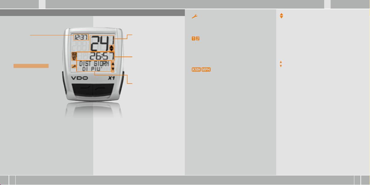
D GB F I
X1 VDO CYCLECOMPUTING58
I F GB D
www.vdocyclecomputing.com X1 59
1. Display
Indicatore service
Indicatore di differenza tra velocità
Il display può essere
Indica che la vostra bici deve essere portata in
(attuale) e velocità (media)
suddiviso in 4 segmenti:
assistenza. L’intervallo service può essere definito
Il computer confronta la velocità attuale con
singolarmente per bici 1 e bici 2.
la velocità media.
Segmento 1
Segmento 2
L’indicatore segnala:
Mostra sempre
Mostra la velocità
Indicatore bici 1/bici 2
B
se la velocità attuale è superiore alla media
l’ora attuale
attuale.
Il computer può lavorare con due diverse impos-
(+1 KMH)
tazioni per due bici. L’indicatore segnala quale
B
se è inferiore alla media (-1KMH)
delle due bici avete scelto di utilizzare.
B
oppure se corrisponde alla media
Segmento 3
I chilometri complessivi vengono contati e salvati
(tolleranza +/- 1 KMH).
Inoltre troverete nel display
Mostra il valore della fun-
separatamente per bici 1 e bici 2.
gli elementi indicatori.
zione/informazione da voi
Indicatore del comando menu
La descrizione dei singoli
selezionata.
Unità di misura (KMH o MPH)
Se viene richiamato un sottomenu, questi indi-
indicatori è riportata sul
Il computer può mostrare sia il valore KMH
catori lampeggiano e segnalano che vi sono altre
lato destro.
che MPH. I percorsi vengono indicati in chilo-
possibilità di selezione oppure che il computer
Segmento 4
metri o in miglia.
aspetta l’inserimento di dati (modalità impos-
Mostra nella riga superiore
L’indicatore mostra l’unità di misura selezionata.
tazione).
(riga info) il nome della
funzione selezionata. La
seconda riga (riga menu)
mostra le seguenti voci:
B
“DI PIU’” se vi sono
ulteriori informazioni.
B
“SELEZIONA” se vi è
un’altra possibilità di
scelta.
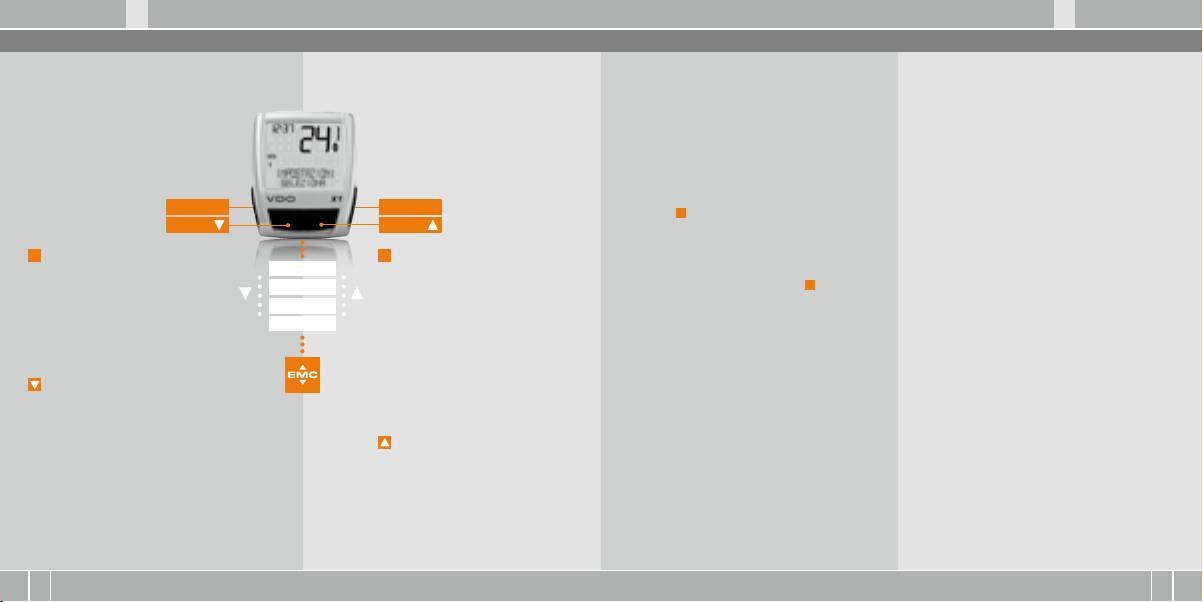
D GB F I
X1 VDO CYCLECOMPUTING60
I F GB D
www.vdocyclecomputing.com X1 61
2. Comando
3. Funzioni di informazioni in modalità funzioni
Per facilitare l’uso del vostro computer abbiamo
Gli indicatori menu nel display lampeggianti
DIST GIORN
TEMPO IMPIEG
creato il sistema EMC = Easy Menu Control.
segnalano che vi sono altre possibilità di selezione.
ndica il percorso del training attuale dall’ultimo
Indica il tempo corsa del training giornaliero attu-
L’EMC facilita l’uso del computer mediante una
In modalità funzioni e in modalità impostazioni
reset. Valore massimo 999,99 km. Quando si supera
ale dall’ultimo reset. Massimo 23:59:59 HH:MM:SS
guida menu con testo esteso, simile a quelle
il comando avviene mediante i 4 tasti.
il valore massimo il contatore ritorna a zero. Con-
Quando si supera il valore massimo la misurazione
maggiormente in uso nei telefoni cellulari.
temporaneamente vengono azzerati i valori di tem-
della corsa riparte da zero. Nel contempo si riazze-
po corsa e velocità media.
rano il training giornaliero e la velocità media.
DIST GIORN/DI PIU’
VELOC MEDIA
DI PIU’ indica che nel menu principale DIST GIORN
Indica la velocità media, calcolata da training gior-
vi è un sottomenu. Per aprire i sottomenu preme-
naliero e corsa dall’ultimo reset. Precisione: 2 cifre
C = CLEAR
M = MENU
re il tasto
M
. Il sottomenu comprende:
dopo la virgola. La velocità media viene ricalcolata
DOWN
UP
B
Totale KM BICI 1 fino massimo 99.999 km.
quando il training giornaliero o la corsa superano il
B
Totale KM BICI 2 fino massimo 99.999 km.
valore massimo.
C
= CLEAR
M
= MENU
B
Somma totale chilometri bici 1 + bici 2
FUNCIONE 3
In modalità funzioni:
In modalità funzioni:
fino massimo 199.999 KM.
VELOC MAX
B
Dal sottomenu tornare indietro
FUNCIONE 4
B
Richiamare il sottomenu disponibile.
Per uscire dal sottomenu premere
C
.
Indica la velocità massima nel training attuale
di un livello di menu.
B
Oppure confermare la selezione.
dall’ultimo reset. Precisione: 2 cifre dopo la virgola.
FUNCIONE 5
In modalità impostazione:
I sottomenu sono riconoscibili per
FUNCIONE 6
B
Ritornare alla modalità funzioni.
mezzo degli indicatori di menu
B
Correggere un dato impostato.
lampeggianti.
B
Tornare indietro di una cifra.
In modalità impostazione:
B
Selezionare impostazione.
= DOWN
B
Confermare un’impostazione
In modalità funzioni:
attuata.
B
Scorrere le funzioni verso il basso.
B
Confermare una selezione inserita.
In modalità impostazione:
B
Scorrere verso il basso in modalità.
= UP
impostazione.
In modalità funzioni:
B
Diminuire una cifra.
B
Scorrere le funzioni verso l’alto.
In modalità impostazione:
B
Acorrere verso l’alto in modalità
impostazione .
B
Aumentare una cifra..

D GB F I
X1 VDO CYCLECOMPUTING62
I F GB D
www.vdocyclecomputing.com X1 63
4 Installazione
4.2 Montaggio della batteria nel computer >>> P03
4.1 Montaggio di sensore, magnete e supporto per manubrio >>> P01
Al momento dell’acquisto il vostro computer
CONSIGLIO per il cambio batteria: VDO raccoman-
VDO è completo di batteria 3V (mod. 2032).
da di cambiare la batteria una volta all’anno.
In caso di montaggio con una forcella molleg-
step 4 Posare il cavo dal sensore già montato lun-
L’apparecchi viene fornito con la batteria è già
Acquistate per tempo una batteria nuova per assi-
giata controllare sempre la compressione della
go il cavo del freno fino al manubrio (fissare con la
montata. Per cambiare la batteria compiere le
curare il perfetto funzionamento.
molla della forcella. Il cavo deve avere un gioco
fascetta per cavi in dotazione). Ideale: attorciglia-
seguenti operazioni:
Quando si esegue il cambio di batteria tutte le im-
sufficiente.
re insieme il cavo del sensore e quello del freno.
postazione base del computer ritornano ai valori
step 1 Inserire la batteria nell’alloggiamento del
di default. Per questo motivo prima di togliere la
ATTENZIONE: pericolo di crepe nei cavi
step 5 Decidere se si vuole eseguire il montaggio a
computer con il polo+ verso l’alto.
batteria vecchia è opportuno annotarsi le misure
manubrio o sull’attacco manubrio e di conseguen-
delle ruote impostate e i chilometri totali finora
step 1 Inserire la base di gomma sotto il sensore.
za ruotare di 90° la base del supporto del manubrio.
step 2 Accertarsi che la batteria non sia danneggiata.
percorsi per la vostra bici 1 e bici 2. Questi valori
Montare il sensore sul lato della forcella sul quale
A questo punto svitare le viti nel supporto, estrar-
dovranno essere riprogrammati dopo aver inseri-
avete previsto di montare il computer sul manu-
re la base ed inserirla ruotata di 90°, infine serrare
step 3 Assicurarsi che la guarnizione in gomma
to la nuova batteria
brio (destra o sinistra), utilizzando la fascetta per
nuovamente le viti.
aderisca perfettamente sul coperchio dello scom-
cavi in dotazione (dapprima lenta, non serrare
parto della batteria.
a fondo).
ATTENZIONE: non forzare le viti.
step 4 Inserire il coperchio dello scomparto della
A seconda dello spazio disponibile il sensore può
step 6 Inserire la fascetta per cavi nella fessura
batteria nell’apertura e girarlo con una monetina
essere montato davanti sulla forcella, interna-
presente nel supporto del manubrio, guidarla in-
verso destra fino in fondo (ca. 1/3 di giro).
mente alla forcella oppure dietro quest’ultima.
torno al manubrio o all’attacco manubrio e strin-
>>> P02
gere saldamente (non serrare a fondo).
4.3 Inserimento del computer nel supporto per manubrio >>> P04
step 2 Posizionare il magnete per raggi intorno a
step 7 Per il montaggio a manubrio: orientare
un raggio esterno. L’anima magnetica argentata
l’angolo di inclinazione del computer per garanti-
Il sistema twist click VDO garantisce un colle-
step 2 Ruotare ”twist” il computer verso destra
è rivolta verso il sensore. Allineare il magnete alla
re una perfetta leggibilità. Infine serrare a fondo
gamento sicuro del computer al supporto per
tenendolo nella posizione delle ore 12.00 e bloc-
marcatura del sensore ad una distanza di circa
la fascetta per cavi.
manubrio.
carlo “click” nell’apposito supporto.
1 – 5 mm.
Tagliare con le pinze le estremità in eccesso.
step 1 Inserire il computer nel supporto tenendo-
step 3 Per estrarre il computer girarlo verso sinistra
step 3 Orientare definitivamente e fissare sensore
lo nella posizione delle ore 10.00.
(non spingere o estrarre con eccessiva forza).
e magnete: serrare la fascetta per cavi e premere
Aiuti per ricordare:
con forza il magnete
Dentro (avvitare) verso destra, Svitare verso sinistra
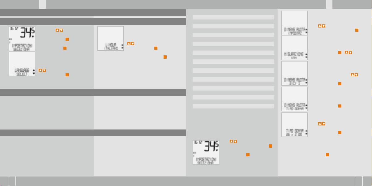
D GB F I
X1 VDO CYCLECOMPUTING64
I F GB D
www.vdocyclecomputing.com X1 65
5. Impostazioni di base
valore mm valore inch
16 x 1,75 1272 50,1
5.1 Impostazione lingua
20 x 1,75 1590 62,6
24 x 1 ⅜ 1948 76,7
Con n DIMENS RUOTA/
Con i tasti andate su
24 x 1,75 1907 75,1
IMPOSTAZ Confermare con
M
.
IMPOSTAZIONI/SELEZIONA.
26 x 1 1973 77,7
Confermare con
M
.
26 x 1,5 2026 79,8
Ora siete in modalità impostazi-
per LINGUA ITALIANO.
26 x 1,6 2051 80,7
oni (premendo
C
per 3 secondi
Confermare con
M
.
26 x 1,75 2070 81,5
MISURAZIONE/KMH
ritornate in modalità funzioni).
26 x 1,9 2089 82,2
Confermare con
M
o per
ITALIANO SELEZION OK? Confermare con
M
.
26 x 2,00 2114 83,2
cambiare in MPH.
26 x 2,125 2133 84,0
Feedback del computer: LINGUA SELEZIONE OK.
26 x 1 ⅜ 2105 82,9
per LANGUAGE SELECT.
Il computer ritorna automaticamente nel menu
26 x ¾ 1954 76,9
Confermare con
M
.
di partenza IMPOSTAZIONI/SELEZIONA.
27 x 1 ¼ 2199 86,6
DIMENS RUOTA/BICI 1 (con
28 x 1,5 2224 87,6
per l’impostazione della bici 2)
28 x 1,75 2268 89,3
Confermare con
M
.
28 x 1 ½ 2265 89,2
5.2 Impostazione e misurazione della misura della ruota
28 x 1 ⅜ 2205 86,8
30-622 2149 84,6
Per consentire al vostro computer VDO di esegui-
Vi sono 2 alternative:
32-622 2174 85,6
DIMENS RUOTA/TIPO GOMMA:
re una corretta misurazione dovete impostare la
37-622 2205 86,8
Confermare con
M
.
misura della vostra ruota (circonferenza di rotola-
40-622 2224 87,6
mento della ruota).
TIPO GOMMA/SELECT
Con selezionate ora
Come impostare la misura delle gomme
la vostra gomma.
5.2.1 Scelta da una tabella delle gomme
selezionando la gomma:
Confermare con
M
.
La tabella delle gomme contiene tutti i modelli
I valori riportati nella tabella sono indicativi e
Con in IMPOSTAZIONI/
Appare la domanda di controllo
di gomme più comunemente usati. Se il modello
possono differire a seconda di marca, altezza e
SELEZIONA. Confermare con
M
.
“Tipo gomma”/SELEZION OK?
della vostra gomma non è elencato vi consigliamo
profilo della gomma. Pertanto tra il percorso mi-
Ora siete in modalità impostazi-
Se la misura della gomma corrisponde a quella
di inserire manualmente la misura della ruota.
surato e la velocità visualizzata potranno esservi
oni (premendo
C
per 3 secondi
desiderata, confermare con
M
.
alcune differenze.
ritornate in modalità funzioni).
Il display conferma DIMENS RUOTA/IMPOST OK.
Ritorno automatico in IMPOSTAZIONI/SELEZIONA.
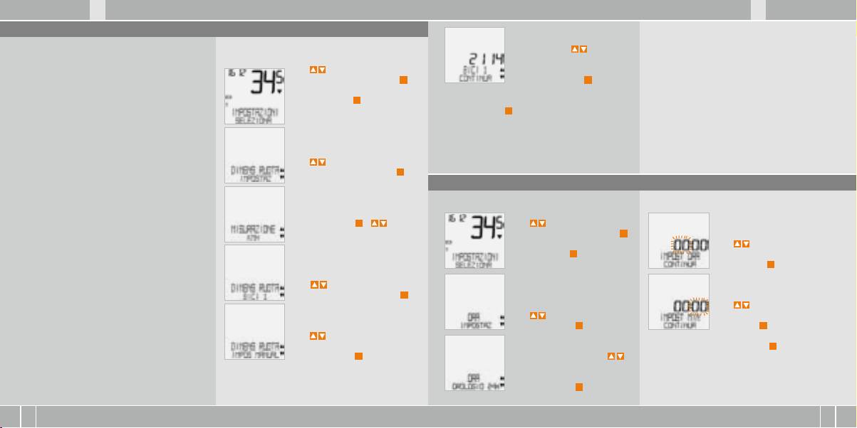
D GB F I
X1 VDO CYCLECOMPUTING66
I F GB D
www.vdocyclecomputing.com X1 67
5.2.2 Impostazione mediante la circonferenza ruota >>> P05
BICI 1 ….IMPOST RUOTA/
ATTENZIONE: le impostazioni di default sono
Per l’inserimento manuale della misura della ruota
Procedura per impostare la misura della ruota:
CONTINUA. Con impostate
2155 mm per la bici 1 e 2000 mm per la bici 2.
dovete in primo luogo misurare la circonferenza di
ora la circonferenza di rotola-
Se non viene impostata la misura della ruota,
rotolamento della vostra ruota.
Con in IMPOSTAZIONI/
mento misurata. Confermare
il computer lavora con le impostazioni di
SELEZIONA. Confermare con
M
.
l’impostazione con
M
.
default. I valori così misurati di velocità, percorso
Misurazione della circonferenza
Ora siete in modalità impostazi-
ecc. possono differire sensibilmente dai valori
di rotolamento della ruota:
oni (premendot
C
per
Viene visualizzata la domanda: BICI 1/SELEZ OK?
effettivi.
3 secondi ritornate in modalità
Confermare con
M
.
step 1 Portare la valvola della ruota anteriore
funzioni).
in posizione perfettamente perpendicolare al
Il display conferma. DIMENS RUOTA/IMPOST OK
pavimento
Ritorno automatico in IMPOSTAZIONI/SELEZIONA
step 2 Tracciare sul pavimento un segno in
Con n DIMENS RUOTA/
questo punto (ad es. con gessetto).
IMPOSTAZ. Confermare con
M
.
5.3 Impostazione orario
step 3 Far avanzare la ruota di un giro completo
in avanti, fino a quando la valvola è di nuovo per-
Impostazione dell’orario:
pendicolare al pavimento.
MISURAZIONE/KMH
Confermare con
M
o
Con in IMPOSTAZIONI/
step 4 Tracciare un segno sul pavimento anche
per cambiare in MPH
SELEZIONA. Confermare con
M
.
ORA...IMPOST ORA/CONTINUA
in questo punto.
Ora siete in modalità impostazi-
Con impostate le ore.
oni (premendo
C
per 3 secondi
Confermare l’impostazione
step 5 Misurare la distanza tra i due segni tracciati.
ritornate in modalità funzioni).
delle ore con
M
.
Questa misura è la circonferenza della ruota
DIMENS RUOTA/BICI 1
(circonferenza di rotolamento).
(con per l’impostazione
della bici 2). Confermare con
M
.
ORA...IMPOST MIN/CONTINUA
step 6 Inserite nel vostro computer VDO la circon-
Con impostate i minuti.
ferenza della ruota così misurata.
Con in ORA/IMPOSTAZ
Confermare l’impostazione dei
Confermare con
M
.
minuti con
M
.
ATTENZIONE: se avete selezionato il valore KMH la
Con n DIMENS RUOTA/
circonferenza della ruota deve essere inserita in mm
IMPOS MANUAL.
ORA/SELEZ OK? Confermare con
M
.
(se avete selezionato il valore MPH la circonferenza
Confermare con
M
.
ORA/OROLOGIO 24H (con
della ruota deve essere inserita in pollici (inch)).
potete passare alla visualizza-
Il display conferma: ORA/IMPOST OK.
zione su 12 ore).
Ritorno automatico in IMPOSTAZIONI/SELEZIONA.
Confermare con
M
.
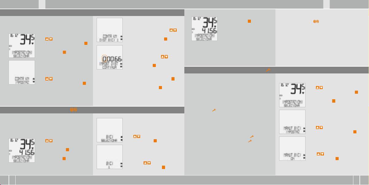
D GB F I
X1 VDO CYCLECOMPUTING68
I F GB D
www.vdocyclecomputing.com X1 69
5.4 Impostazione totale chilometri
BICI 1/SELEZION OK?
La bici selezionata 1) o 2) viene visualizzata in basso
In qualunque momento potete programmare il con-
Confermare con
M
.
a sinistra nel display. ( )
tatore di percorso (ad es. alla fine di una stagione).
Il display conferma
CONTA KM/DIST BICI 1 (con
BICI/SELEZION OK
ATTENZIONE, nota importante: quando si passa
ntrate nell’impostazione per la
Ritorno automatico in
da bici 1 a 2 o viceversa vengono riazzerati i dati
Con in IMPOSTAZIONI/
BICI 2). Confermare con
M
.
IMPOSTAZIONI/SELEZIONA
del training giornaliero, la corsa, la velocità
SELEZIONA. Confermare con
M
.
media e la velocità massima dell’ultimo training.
Ora siete in modalità impostazi-
DIST BICI 1…..IMPOST DIST/
oni (premendo
C
per 3 secondi
CONTINUA. Per impostare la cifra
ritornate in modalità funzioni).
lampeggiante premere . Per
richiamare la cifra successiva
confermare con
M
. Ripetere
queste operazioni fino a
5.6 Visualizzazione intervallo service
quando l’ultima cifra a destra
Con in CONTA KM/
lampeggia. Confermare con
M
.
La visualizzazione intervallo service vi ricorda che
Come impostare gli intervalli service
IMPOSTAZ. Confermare con
M
.
dovete far controllare la bici in officina.
DIST BICI 1/SELEZ OK? Confermare con
M
.
L’intervallo service può essere inserito/disinserito
Con in IMPOSTAZIONI/
(ON o OFF). Gli intervalli service personalizzati posso-
SELEZIONA. Confermare con
M
.
Il display conferma DIST BICI 1/IMPOST OK.
no essere impostati separatamente per 2 bici.
Ora siete in modalità impostazi-
Ritorno automatico in IMPOSTAZIONI/SELEZIONA.
Quando è stato compiuto il percorso intervallo
oni (premendo
C
per 3 secondi
service impostato:
ritornate in modalità funzioni).
5.5 Commutazione bici 1/bici 2
B
il simbolo lampeggia nel display.
B
la riga delle informazioni indica MANUT. BICI/BICI 1
Il vostro computer VDO può essere utilizzato per
Adesso dovete controllare la bici personalmente
2 bici. Se si passa dalla bici 1 alla bici 2, prima di
oppure farla controllare dal vostro rivenditore.
partire occorre impostare il computer sulla bici
JPremere un tasto a piacere. Il testo „MANUT.
Con in MANUT. BICI/
utilizzata
BICI/BICI 1“ scompare di nuovo. Dopo altri 50 km
IMPOSTAZ. Confermare con
M
.
Con in BICI/SELEZIONA
scompare di nuovo anche il simbolo .
Con in IMPOSTAZIONI/
Confermare con
M
.
Potete anche disattivare il simbolo lampeg-
SELEZIONA
giante. Per questa operazione inserite di nuovo
Confermare con
M
.
l’intervallo assistenza.
MANUT. BICI/ON
Ora siete in modalità impostazi-
(Con inserire OFF)
oni (premendo
C
per 3 secondi
Confermare con
M
.
ritornate in modalità funzioni).
BICI 1 (con impostate su
BICI 2)Confermare con
M
.
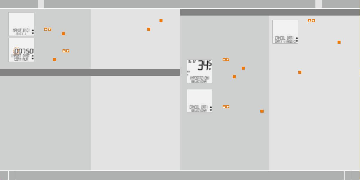
D GB F I
X1 VDO CYCLECOMPUTING70
I F GB D
www.vdocyclecomputing.com X1 71
5.8 Funzioni reset
Ripetere queste operazioni fino a quando l’ultima
cifra a destra lampeggia. Confermare con
M
.
Con la funzione RESET si possono riazzerrare a scelta:
Con nei dati che volete
MANUT. BICI/BICI 1
B
DATI VIAGGIO
riazzerare:
Con passare a BICI 2).
BICI 1/SELEZ OK? Confermare con
M
.
B
TOT DIST 1+2
B
CANCEL DATI/DATI VIAGGIO
Confermare con
M
.
Nelle varie modalità reset vengono cancellate
OPPURE
Il display conferma: MANUT. BICI/IMPOST OK.
le seguenti informazioni:
B
CANCEL DATI/TOT DIST 1+2
BICI 1…IMPOST DIST/CONTINUA
Ritorno automatico in IMPOSTAZIONI/SELEZIONA.
B
DATI VIAGGIO: training giornaliero, corsa,
Confermare la scelta con
M
.
Per impostare la cifra lampeg-
velocità media, velocità massima
giante premere . Per richia-
B
TOT DIST 1+2: totale km, km bici 1, km bici 2
Domanda: SELEZIONE DATI/CANCELLA?
mare la cifra successiva confer-
mare con
M
.
Con
in IMPOSTAZIONI/
ATTENZIONE: questa operazione non può
SELEZIONA.
essere annullata.
Confermare con
M
. Ora siete
5.7 Modalità sleep
in modalità impostazioni
Confermare con
M
, solo se si desidera cancellare
(premendo
C
per 3 secondi
i dati selezionati.
Il vostro computer VDO è dotato di una funzione
La modalità sleep si inserisce quando per
ritornate in modalità funzioni).
Il display conferma: CANCEL DATI/CANCELLA OK.
modalità sleep. In modalità sleep il display si
5 minuti non vengono elaborati impulsi di velo-
Ritorno automatico in IMPOSTAZIONI/SELEZIONA.
disattiva quasi totalmente per risparmiare la
cità e non viene premuto alcun tasto.
carica della batteria. Rimangono visualizzati
l’orario e l’intervallo service.
La modalità sleep termina quando vengono di
nuovo elaborati impulsi di velocità (in marcia)
oppure quando viene digitato un tasto.
Con
in CANCEL DATI/
SELEZIONA. Confermare con
M
.

D GB F I
X1 VDO CYCLECOMPUTING72
I F GB D
www.vdocyclecomputing.com X1 73
6. Condizioni di garanzia
Campo di misura totale chilometri:
Campo di regolazione circonferenza ruota:
La VDO Cycle Parts rilascia per il vostro computer
Per tutti i reclami e i casi di garanzia vi preghia-
max. 199.999 km oppure mi
da 100 mm a 3999 mm (da 3,9 a 157,4 inch)
VDO una garanzia di 5 anni dalla data di acquisto.
mo di rivolgervi al vostro rivenditore di fiducia
La garanzia copre i difetti del materiale e di lavo-
dal quale avete acquistato l’apparecchio. Diver-
razione del computer, del sensore/trasmettitore
samente potrete spedire il vostro reclamo diret-
e del supporto per manubrio. Sono esclusi dalla
tamente a:
7. Eliminazione dei guasti
garanzia i cavi, la batteria e i materiali di montag-
gio. La garanzia è operante solo per le parti che
Cycle Parts GmbH
Segue un elenco dei probabili errori e delle loro cause, con eventuali rimedi da adottare:
non sono state aperte (eccezione: scomparto della
Große Ahlmühle 33
batteria del computer) e che non presentano seg-
D-76865 Rohrbach (Germany)
Errore Probabile causa Rimedio
ni di forzature o danni intenzionali.
Si prega di conservare con cura il documento
Per eventuali problemi tecnici potete contattarci
Segmenti dimezzati nella visualiz-
Dopo il cambio batteria il soft-
Togliete la batteria
d’acquisto, da esibire in caso di reclamo.
al seguente numero hotline:
zazione (ad es. dopo un cambio di
ware del computer non gira
ed inserite la nuova
Se il vostro reclamo è legittimo vi sarà consegnato
+49 (0) 63 49 - 96 35 - 10.
batteria)
correttamente
un apparecchio sostitutivo di pari valore. Si esclu-
de il diritto di sostituzione con modello identico
Maggiori informazioni sono disponibili nel sito:
Velocità non visualizzata Distanza eccessiva tra sensore
Correggere la posizione del
nei casi in cui il modello reclamato non sia più
www.vdocyclecomputing.com
e magnete
sensore e del magnete
disponibile a seguito di un cambio di modello.
Ci riserviamo eventuali modifiche tecniche fina-
Velocità non visualizzata La testa del computer non è
Inserire la testa del computer
lizzate al perfezionamento del prodotto.
inserita correttamente nel sup-
nel supporto da manubrio fino
porto per manubrio
a battuta (CLICK) e girare
8. Specifiche Tecniche
Velocità non visualizzata La circonferenza della bici non
Impostare la circonferenza
è impostata correttamente op-
della ruota
Computer:
Temperatura d’esercizio del display:
pure è su zero
ca. 45 x 52 x 16 mm, peso ca. 45 g
da -15 °C a +60 °C
Supporto per manubrio:
Range di velocità:
La visualizzazione è debole Batteria scarica Controllare, eventualmente
peso: ca. 15 g
con misura della ruota 2155 mm, min 2,5 km/h,
sostituire la batteria
Trasmettitore:
max 199,5 km/h
peso ca. 20 g
Campo di misura tempo corsa:
La visualizzazione è debole Le temperature inferiori a 5°
In normali condizioni di tem-
Batteria computer:
max. 23:59:59 HH:MM:SS
ritardano la visualizzazione
peratura la visualizzazione si
3V, mod. 2032
Campo di misura contatore training giornaliero:
normalizza.
Durata batteria computer:
max 999,99 km oppure mi
1200 ore di corsa, ca. 24.000 km (15.000 M)
Campo di misura totale km 1 e 2:
max. 99.999 km oppure mi
X1 VDO CYCLECOMPUTING74
www.vdocyclecomputing.com X1 75
D
GB
F
I
Korrekte Entsorgung dieses Produkts
Correct Disposal of This Product
Comment éliminer ce produit
Corretto smaltimento del prodotto
(Elektromüll)
(Waste Electrical & Electronic Equipment)
(déchets d‘équipements électriques
(rifiuti elettrici ed elettronici)
et électroniques)
(Anzuwenden in den Ländern der Europäischen Uni-
(Applicable in the European Union and other Euro-
(Applicabile in i paesi dell‘Unione Europea e in quelli
on und anderen europäischen Ländern mit einem
pean countries with separate collection systems).
(Applicable dans les pays de l‘Union Européen et
con sistema di raccolta differenziata). Marchio ri-
separaten Sammelsystem). Die Kennzeichnung auf
This marking shown on the product or its literature,
aux autres pays européens disposant de systèmes
portato sul prodotto o sulla sua documentazione
dem Produkt bzw. auf der dazugehörigen Litera-
indicates that it should not be disposed with other
de collecte sélective). Ce symbole sur le produit ou
indica che il prodotto non deve essere smaltito con
tur gibt an, dass es nach seiner Lebensdauer nicht
household wastes at the end of its working life.
sa documentation indique qu‘il ne doit pas être
altri rifiuti domestici al termine del ciclo di vita. Per
zusammen mit dem normalen Haushaltsmüll ent-
To prevent possible harm to the environment or
éliminé en fin de vie avec les autres déchets ména-
evitare eventuali danni all‘ambiente o alla salute
sorgt werden darf. Entsorgen Sie dieses Gerät bitte
human health from uncontrolled waste disposal,
gers. L‘élimination incontrôlée des déchets pouvant
causati dall‘inopportuno smaltimento dei rifiuti, si
getrennt von anderen Abfällen, um der Umwelt bzw.
please separate this from other types of wastes
porter préjudice à l‘environnement ou à la santé
invita l‘utente a separare questo prodotto da altri ti-
der menschlichen Gesundheit nicht durch unkont-
and recycle it responsibly to promote the sustain-
humaine, veuillez le séparer des autres types de dé-
pi di rifiuti e di riciclarlo in maniera responsabile per
rollierte Müllbeseitigung zu schaden. Recyceln Sie
able reuse of material resources. Household users
chets et le recycler de façon responsable. Vous favo-
favorire il riutilizzo sostenibile delle risorse materi-
das Gerät, um die nachhaltige Wiederverwertung
should contact either the retailer where
riserez ainsi la réutilisation durable des ressources
ali. Gli utenti domestici sono invitati a contattare il
von stofflichen Ressourcen zu fördern. Private
they purchased this product, or their local govern-
matérielles. Les particuliers sont invités à contacter
rivenditore presso il quale è stato acquistato il pro-
Nutzer sollten den Händler, bei dem das Produkt
ment office, for details of where and how they can
le distributeur leur ayant vendu le produit ou à se
dotto o l‘ufficio locale preposto per tutte le informa-
gekauft wurde, oder die zuständigen Behörden
take this item for environmentally safe recycling.
renseigner auprès de leur mairie pour savoir où et
zioni relative alla raccolta differenziata e al riciclag-
kontaktieren, um in Erfahrung zu bringen, wie Sie
Business users should contact their supplier and
comment ils peuvent se
gio per questo tipo di prodotto. Gli utenti aziendali
das Gerät auf umweltfreundliche Weise recyceln
check the terms and conditions of the purchase
débarrasser de ce produit afin qu‘il soit recyclé en
sono invitati a contattare il proprio fornitore e
können. Gewerbliche Nutzer sollten sich an Ihren
contract. This product should not be mixed with
respectant l‘environnement. Les entreprises sont
verificare i termini e le condizioni del contratto di
Lieferanten wenden und die Bedingungen des Ver-
other commercial wastes for disposal.
invitées à contacter leurs fournisseurs et à consul-
acquisto. Questo prodotto non deve essere smaltito
kaufsvertrags konsultieren. Dieses Produkt darf
ter les conditions de leur contrat de vente. Ce pro-
unitamente ad altri rifiuti commerciali.
nicht zusammen mit anderem Gewerbemüll ent-
duit ne doit pas être éliminé avec les autres déchets
sorgt werden.
commerciaux.
