MSI G31M3: инструкция
Раздел: Профоборудование
Тип: Аппарат
Инструкция к Аппарату MSI G31M3
G31M3 Series
MS-7528 (V1.X) Mainboard
G52-75281X4
i
PDF 檔案使用 "pdfFactory" 試用版本建立 www.ahasoft.com.tw/FinePrint

Copyright Notice
The material in this document is the intellectual property of MICRO-STAR
INTERNATIONAL. We take every care in the preparation of this document, but no
guarantee is given as to the correctness of its contents. Our products are under
continual improvement and we reserve the right to make changes without notice.
Trademarks
All trademarks are the properties of their respective owners.
NVIDIA, the NVIDIA logo, DualNet, and nForce are registered trademarks or trade-
marks of NVIDIA Corporation in the United States and/or other countries.
AMD, Athlon™, Athlon™ XP, Thoroughbred™, and Duron™ are registered trade-
marks of AMD Corporation.
®
®
Intel
and Pentium
are registered trademarks of Intel Corporation.
®
PS/2 and OS
/2 are registered trademarks of International Business Machines
Corporation.
®
Windows
95/98/2000/NT/XP are registered trademarks of Microsoft Corporation.
®
Netware
is a registered trademark of Novell, Inc.
®
Award
is a registered trademark of Phoenix Technologies Ltd.
®
AMI
is a registered trademark of American Megatrends Inc.
Revision History
Revision Revision History Date
V1.0 First release April 2008
Technical Support
If a problem arises with your system and no solution can be obtained from the user’s
manual, please contact your place of purchase or local distributor. Alternatively,
please try the following help resources for further guidance.
Visit the MSI website for FAQ, technical guide, BIOS updates, driver updates,
and other information: http://global.msi.com.tw/index.php?
func=faqIndex
Contact our technical staff at: http://support.msi.com.tw/
ii
PDF 檔案使用 "pdfFactory" 試用版本建立 www.ahasoft.com.tw/FinePrint

Safety Instructions
1. Always read the safety instructions carefully.
2. Keep this User’s Manual for future reference.
3. Keep this equipment away from humidity.
4. Lay this equipment on a reliable flat surface before setting it up.
5. The openings on the enclosure are for air convection hence protects the equip-
ment from overheating. DO NOT COVER THE OPENINGS.
6. Make sure the voltage of the power source and adjust properly 110/220V be-
fore connecting the equipment to the power inlet.
7. Place the power cord such a way that people can not step on it. Do not place
anything over the power cord.
8. Always Unplug the Power Cord before inserting any add-on card or module.
9. All cautions and warnings on the equipment should be noted.
10. Never pour any liquid into the opening that could damage or cause electrical
shock.
11. If any of the following situations arises, get the equipment checked by a service
personnel:
† The power cord or plug is damaged.
† Liquid has penetrated into the equipment.
† The equipment has been exposed to moisture.
† The equipment has not work well or you can not get it work according to
User’s Manual.
† The equipment has dropped and damaged.
† The equipment has obvious sign of breakage.
12. DO NOT LEAVE THIS EQUIPMENT IN AN ENVIRONMENT UNCONDITIONED, STOR-
0
0
AGE TEMPERATURE ABOVE 60
C (140
F), IT MAY DAMAGE THE EQUIPMENT.
CAUTION: Danger of explosion if battery is incorrectly replaced.
Replace only with the same or equivalent type recommended by the
manufacturer.
iii
PDF 檔案使用 "pdfFactory" 試用版本建立 www.ahasoft.com.tw/FinePrint

FCC-B Radio Frequency Interference Statement
This equipment has been
tested and found to comply
with the limits for a Class B
digital device, pursuant to Part
15 of the FCC Rules. These limits are designed to provide reasonable protection
against harmful interference in a residential installation. This equipment generates,
uses and can radiate radio frequency energy and, if not installed and used in accor-
dance with the instructions, may cause harmful interference to radio communications.
However, there is no guarantee that interference will not occur in a particular
installation. If this equipment does cause harmful interference to radio or television
reception, which can be determined by turning the equipment off and on, the user is
encouraged to try to correct the interference by one or more of the measures listed
below.
† Reorient or relocate the receiving antenna.
† Increase the separation between the equipment and receiver.
† Connect the equipment into an outlet on a circuit different from that to
which the receiver is connected.
† Consult the dealer or an experienced radio/television technician for help.
Notice 1
The changes or modifications not expressly approved by the party responsible for
compliance could void the user’s authority to operate the equipment.
Notice 2
Shielded interface cables and A.C. power cord, if any, must be used in order to
comply with the emission limits.
VOIR LA NOTICE D ’INSTALLATION AVANT DE RACCORDER AU RESEAU.
Micro-Star International
MS-7528
This device complies with Part 15 of the FCC Rules. Operation is subject to the
following two conditions:
(1) this device may not cause harmful interference, and
(2) this device must accept any interference received, including interference that
may cause undesired operation.
iv
PDF 檔案使用 "pdfFactory" 試用版本建立 www.ahasoft.com.tw/FinePrint
WEEE (Waste Electrical and Electronic Equipment) Statement
v
PDF 檔案使用 "pdfFactory" 試用版本建立 www.ahasoft.com.tw/FinePrint
vi
PDF 檔案使用 "pdfFactory" 試用版本建立 www.ahasoft.com.tw/FinePrint
vii
PDF 檔案使用 "pdfFactory" 試用版本建立 www.ahasoft.com.tw/FinePrint

CONTENTS
Copyright Notice.........................................................................................................ii
Trademarks..................................................................................................................ii
Revision History.........................................................................................................ii
Technical Support......................................................................................................ii
Safety Instructions...................................................................................................iii
FCC-B Radio Frequency Interference Statement.............................................iv
WEEE (Waste Electrical and Electronic Equipment) Statement.......................v
English......................................................................................................................En-1
Specifications....................................................................................................En-2
Central Processing Unit: CPU...........................................................................En-6
Memory...............................................................................................................En-7
Connectors, Jumpers, Slots.............................................................................En-9
Back Panel........................................................................................................En-16
BIOS Setup.......................................................................................................En-18
Software Information......................................................................................En-22
Deutsch....................................................................................................................De-1
Spezifikationen..................................................................................................De-2
Hauptprozessor: CPU.......................................................................................De-6
Speicher.............................................................................................................De-7
Anschlüsse, Steckbrücken und Slots.............................................................De-9
Hinteres Anschlusspaneel.............................................................................De-16
BIOS Setup.......................................................................................................De-18
Software-Information......................................................................................De-22
Français.....................................................................................................................Fr-1
Spécificités.........................................................................................................Fr-2
Central Processing Unit: CPU............................................................................Fr-6
Mémoire...............................................................................................................Fr-7
Connecteurs, Cavaliers, Slots..........................................................................Fr-9
Panneau Arrière...............................................................................................Fr-16
Configuration du BIOS......................................................................................Fr-18
Information de Logiciel.....................................................................................Fr-22
Русский ....................................................................................................................Ru-1
Характеристики ...............................................................................................Ru-2
Центральный процессор (CPU).....................................................................Ru-6
Память ..............................................................................................................Ru-7
Коннекторы, перемычки, разъемы..............................................................Ru-9
Задняя панель ...............................................................................................Ru-16
Настройка BIOS..............................................................................................Ru-18
Сведения о программном обеспечении ...................................................Ru-22
viii
PDF 檔案使用 "pdfFactory" 試用版本建立 www.ahasoft.com.tw/FinePrint

English
G31M3
User’s Guide
English
En-1
PDF 檔案使用 "pdfFactory" 試用版本建立 www.ahasoft.com.tw/FinePrint
MS-7528 Mainboard
Specifications
Processor Support
®
- Intel
Core™2 Duo/ Core™2 Quad/Pentium Dual-Core E2XXX and
Celeron 400 LGA775 processors in LGA775 package.
- Supports 4 pin CPU Fan Pin-Header with Fan Speed Control.
(For the latest information about CPU, please visit
http://global.msi.com.tw/index.php?func=cpuform)
Supported FSB
- 800/1066/1333 MHz
Chipset
®
- North Bridge: Intel
G31 chipset
®
- South Bridge: Intel
ICH7/ ICH7R(optional) chipset
Memory Support
- DDR2 667/800 SDRAM (4GB Max)
- 2 DDR2 DIMMs (240pin / 1.8V)
(For more information on compatible components, please visit
http://global.msi.com.tw/index.php?func=testreport)
LAN (Optional)
®
- Supports Realtek
RTL8111C 10/100/1000 Mb/s
®
- Supports Realtek
RTL8101E 10/100 Mb/s (optional)
- Compliance with PCI 2.2
- Supports ACPI Power Management
Audio
®
- Chip integrated by Realtek
ALC888
- Flexible 8-channel audio with jack sensing
- Supports Vista premium compliance
IEEE 1394 (optional)
- Chip integrated by JMicron 381
- Transfer rate is up to 400Mbps
IDE
- 1 IDE port by ICH7/ICH7R
- Supports Ultra DMA 66/100 mode
- Supports PIO, Bus Master operation mode
SATA
- SATA II ports by ICH7/ICH7R (optional)
- Supports four SATA II devices
- Supports storage and data transfers at up to 3Gb/s
- Supports RAID 0/1/0+1 (for ICH7R only)
En-2
PDF 檔案使用 "pdfFactory" 試用版本建立 www.ahasoft.com.tw/FinePrint
Floppy
- 1 floppy port
English
- Supports 1 FDD with 360KB, 720KB, 1.2MB, 1.44MB and 2.88MB
Connectors
Back panel
- 1 PS/2 mouse port
- 1 PS/2 keyboard port
- 1 serial port (COM1)
- 1 VGA port
- 1 parallel port supporting SPP/EPP/ECP mode
- 4 USB 2.0 Ports
- 1 RJ-45 LAN Jack
- 1 1394 port (optional)
- 6 flexible audio jacks/ 3 flexible audio jacks (optional)
On-Board Pinheaders/ Connectors
- 2 USB 2.0 pinheaders
- 1 CD-in pinheader
- 1 SPDIF-Out pinheader
- 1 IEEE 1394 pinheader (optional)
- 1 Front Panel Audio pinheader
- 1 serial port pinheader
- 1 TPM (optional)
- 1 Chassis Intrusion Switch pinheader
Slots
- 1 PCI Express x16 slot
- 1 PCI Express x 1 slot
- 2 PCI slots
- Support 3.3V/ 5V PCI bus Interface
Form Factor
- Micro-ATX (24.4cm X 21.8cm)
Mounting
- 6 mounting holes
En-3
PDF 檔案使用 "pdfFactory" 試用版本建立 www.ahasoft.com.tw/FinePrint
MS-7528 Mainboard
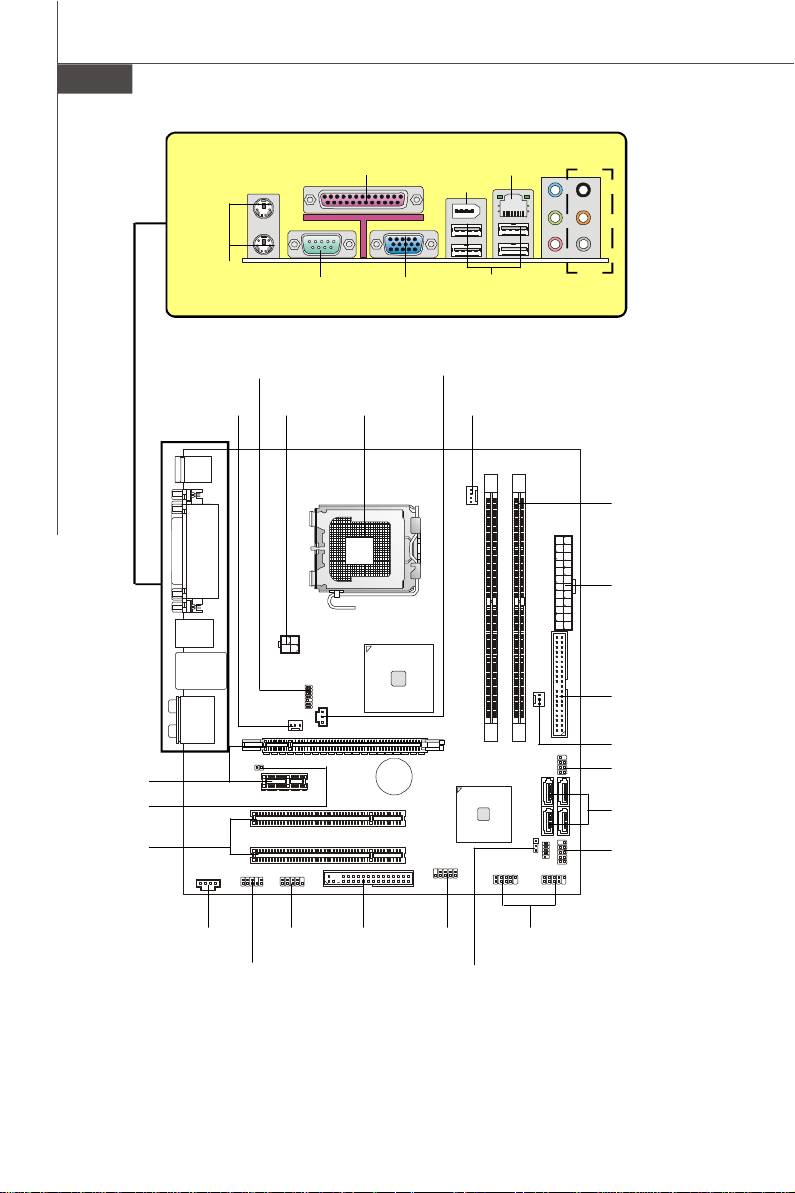
Quick Components Guide of G31M3 Series
(MS-7528 v1.X) Mainboard
En-4
BATT
Parallel Port,
1394
LAN,
(Optional)
p.En-17
Port,
p.En-16
p.En-16
L-In
RS-Out
L-Out
CS-Out
Mic
SS-Out
Mouse/
Keyboard,
Serial Port,
VGA Port,
USB ports,
Audio,
p.En-16
p.En-17
p.En-17
p.En-16
p.En-17
JTPM1,
JSPD1,
p.En-14
p.En-12
SYSFAN1,
JPW1,
CPU,
CPUFAN1,
p.En-9
p.En-14
p.En-5
p.En-9
Memory,
p.En-7
ATX1,
p.En-14
IDE1,
p.En-9
SYSFAN2,
p.En-9
PCIE,
JFP2,
p.En-15
+
p.En-10
JCI1,
SATA1~4,
p.En-11
p.En-10
PCI,
JFP1,
p.En-15
p.En-10
CD_IN1,
JCOM1,
FDD1,
J1394_1,
JUSB1~2,
p.En-12
p.En-11
p.En-9
p.En-10
p.En-11
JAUD1,
JBAT1,
p.En-12
p.En-13
PDF 檔案使用 "pdfFactory" 試用版本建立 www.ahasoft.com.tw/FinePrint

Central Processing Unit: CPU
®
The mainboard supports Intel
processor. The mainboard uses a CPU socket called
Socket 775 for easy CPU installation. If you do not have the CPU cooler, consult your
English
dealer before turning on the computer.
For the latest information about CPU, please visit http://global.msi.com.tw/index.php?
func=cpuform
Important
Overheating
Overheating will seriously damage the CPU and system. Always make sure the
cooling fan can work properly to protect the CPU from overheating. Make sure
that you apply an even layer of thermal paste (or thermal tape) between the CPU
and the heatsink to enhance heat dissipation.
Replaceing the CPU
While replacing the CPU, always turn off the ATX power supply or unplug the
power supply’s power cord from the grounded outlet first to ensure the safety of
CPU.
Overclocking
This mainboard is designed to support overclocking. However, please make
sure your components are able to tolerate such abnormal setting, while doing
overclocking. Any attempt to operate beyond product specifications is not
recommended. We do not guarantee the damages or risks caused by inad-
equate operation or beyond product specifications.
En-5
PDF 檔案使用 "pdfFactory" 試用版本建立 www.ahasoft.com.tw/FinePrint
MS-7528 Mainboard
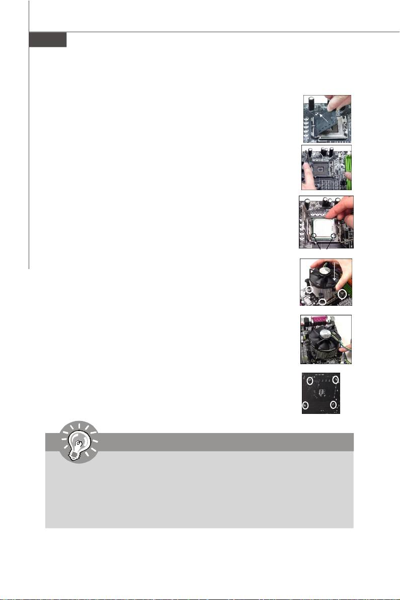
CPU & Cooler Installation Procedures for Socket 775
1. The CPU socket has a plastic cap on it to protect the contact from
damage. Before you have installed the CPU, always cover it to pro-
tect the socket pin.
2. Remove the cap from lever hinge side.
3. The pins of socket reveal.
4. Open the load lever.
5. Lift the load lever up and open the load plate.
6. After confirming the CPU direction for correct mating, put down the
CPU in the socket housing frame. Be sure to grasp on the edge of the
CPU base. Note that the alignment keys are matched.
7. Visually inspect if the CPU is seated well into the socket. If not, take
out the CPU with pure vertical motion and reinstall.
alignment key
8. Cover the load plate onto the package.
9. Press down the load lever lightly onto the load plate, and then
secure the lever with the hook under retention tab.
10.Align the holes on the mainboard with the cooler. Push down the
cooler until its four clips get wedged into the holes of the mainboard.
11.Press the four hooks down to fasten the cooler. Then rotate the
locking switch (refer to the correct direction marked on it) to lock the
hooks.
12.Turn over the mainboard to confirm that the clip-ends are correctly
inserted.
Important
1. Read the CPU status in BIOS.
2. Whenever CPU is not installed, always protect your CPU socket pin with the
plastic cap covered to avoid damaging.
3. Mainboard photos shown in this section are for demonstration of the CPU/
cooler installation only. The appearance of your mainboard may vary depend-
ing on the model you purchase.
En-6
PDF 檔案使用 "pdfFactory" 試用版本建立 www.ahasoft.com.tw/FinePrint
Memory
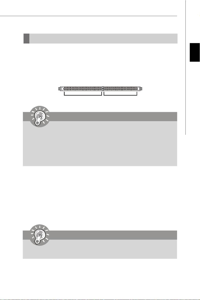
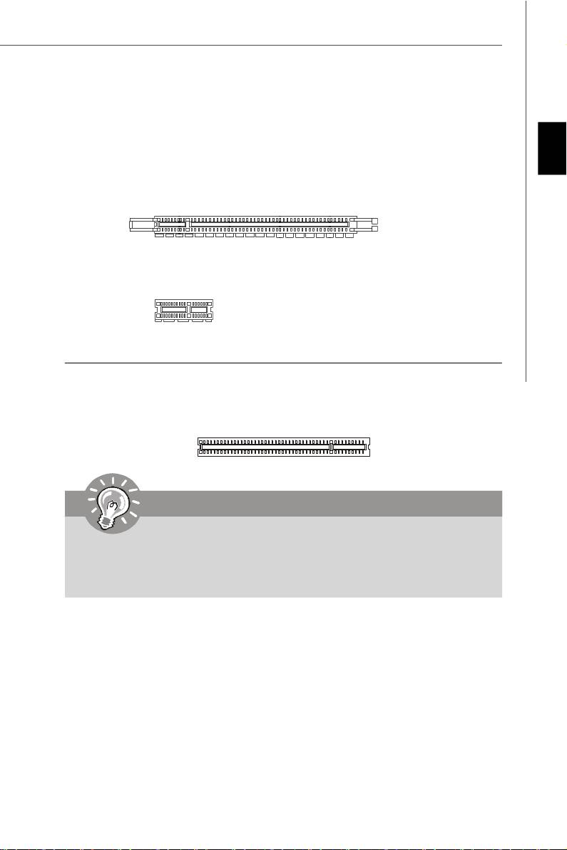
DDR2
English
Specification : 240-pin, 1.8v.
Single channel definition : All DIMM slots are GREEN color.
Dual channels definition : DIMM slot(s) on Channel A are marked in GREEN color.
DIMM slot(s) on Channel B are marked in Orange color.
64x2=128 pin 56x2=112 pin
Important
- DDR2 memory modules are not interchangeable with DDR and the DDR2 stan
dard is not backwards compatible. You should always install DDR2 memory
modules in the DDR2 DIMM slots.
- In Dual-Channel mode, make sure that you install memory modules of the same
type and density in different channel DIMM slots.
- To enable successful system boot-up, always insert the memory modules into the
DIMM1 first.
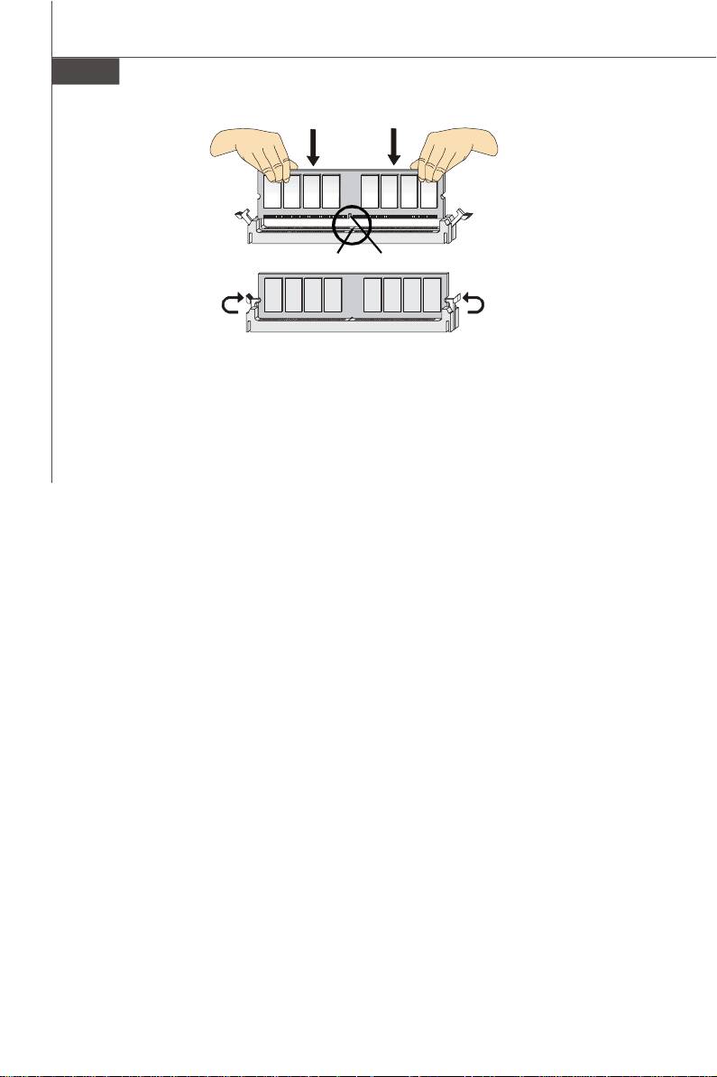
Installing Memory Modules
You can find the notch on the memory modules and the volt on the DIMM slots whether
DDR or DDR2. Follow the procedures below to install the memory module properly.
1.The memory modules has only one notch on the center and will only fit in the right
orientation.
2.Insert the memory module vertically into the DIMM slot. Then push it in until the
golden finger on the memory module is deeply inserted in the DIMM slot. The
plastic clip at each side of the DIMM slot will automatically close.
Important
You can barely see the golden finger if the memory module is properly inserted in
the DIMM slot.
3. Manually check if the memory module has been locked in place by the DIMM slot
clips at the sides.
En-7
PDF 檔案使用 "pdfFactory" 試用版本建立 www.ahasoft.com.tw/FinePrint
MS-7528 Mainboard
Notch
Volt
En-8
PDF 檔案使用 "pdfFactory" 試用版本建立 www.ahasoft.com.tw/FinePrint
Connectors, Jumpers, Slots
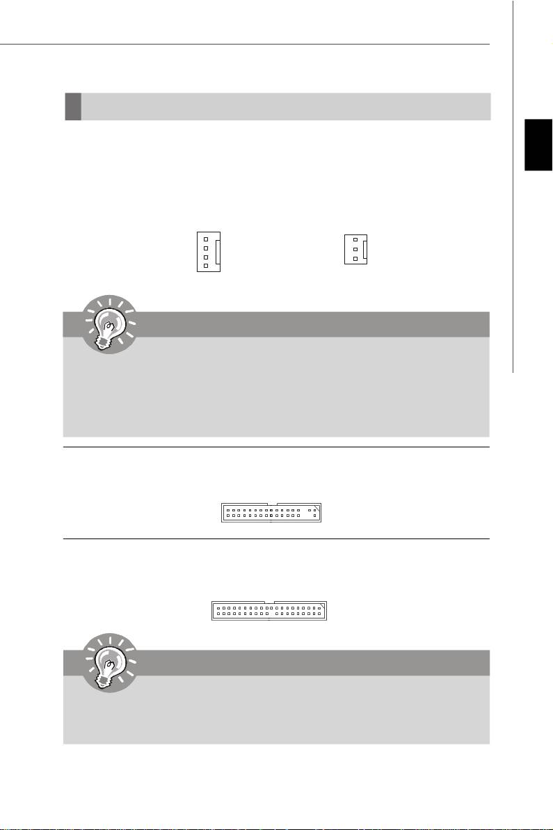
Fan Power Connectors
The fan power connectors support system cooling fan with +12V. The CPU FAN supports
English
Smart FAN function. When connect the wire to the connectors, always take note that the
red wire is the positive and should be connected to the +12V, the black wire is Ground
and should be connected to GND. If the mainboard has a System Hardware Monitor
chipset on-board, you must use a specially designed fan with speed sensor to take
advantage of the fan control.
Control
SENSOR or NC
SENSOR
+12V
+12V
GND
GND
SYS FAN/ NB FAN/
CPU FAN
POWER FAN
Important
1.Please refer to the recommended CPU fans at processor’s official website or
consult the vendors for proper CPU cooling fan.
2.CPUFAN supports fan control. You can install Dual Core Center utility that
will automatically control the CPU fan speed according to the actual CPU
temperature.
3. Fan cooler set with 3 or 4 pins power connector are both available for CPUFAN.
Floppy Disk Drive Connector
This connector supports 360KB, 720KB, 1.2MB, 1.44MB or 2.88MB floppy disk drive.
IDE connector
This connector supports IDE hard disk drives, optical disk drives and other IDE devices.
Important
If you install two IDE devices on the same cable, you must configure the drives
separately to Master/ Slave mode by setting jumpers. Refer to IDE device’s docu-
mentation supplied by the vendors for jumper setting instructions.
En-9
PDF 檔案使用 "pdfFactory" 試用版本建立 www.ahasoft.com.tw/FinePrint
MS-7528 Mainboard
Serial ATA Connector
This connector is a high-speed Serial ATA interface port. Each connector can connect to
one Serial ATA device.
Important
Please do not fold the Serial ATA cable into 90-degree angle. Otherwise, data
loss may occur during transmission.
Front Panel Connectors
These connectors are for electrical connection to the front panel switches and LEDs.
®
The JFP1 is compliant with Intel
Front Panel I/O Connectivity Design Guide.
910
78
Power
Reset
Switch
Switch
Speaker
Power
HDD
Power LED
LED
LED
2
1
12
JFP1
JFP2
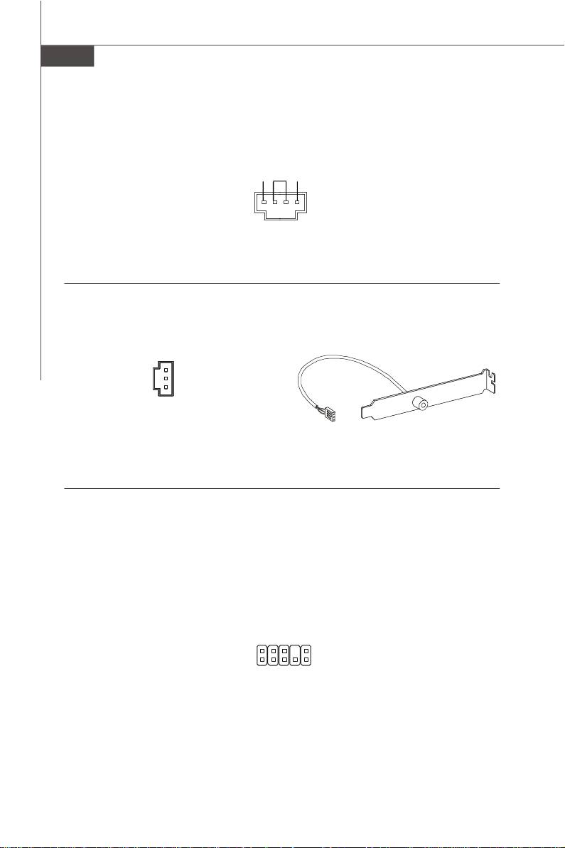
IEEE1394 Connector (Green)
This connector allows you to connect the IEEE1394 device via an optional IEEE1394
bracket.
IEEE1394 Bracket
(Optional)
Key (no pin)
Cable power
TPB+
Ground
TPA+
9
1
10
2
TPB-
TPA-
Ground
Ground
En-10
PDF 檔案使用 "pdfFactory" 試用版本建立 www.ahasoft.com.tw/FinePrint
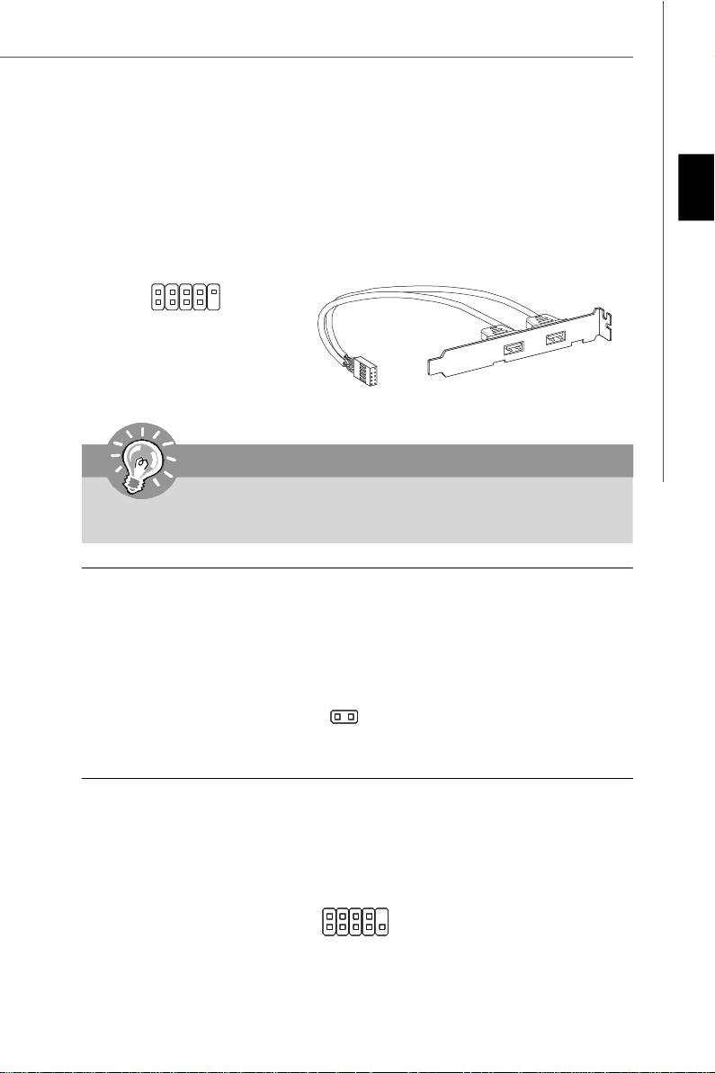
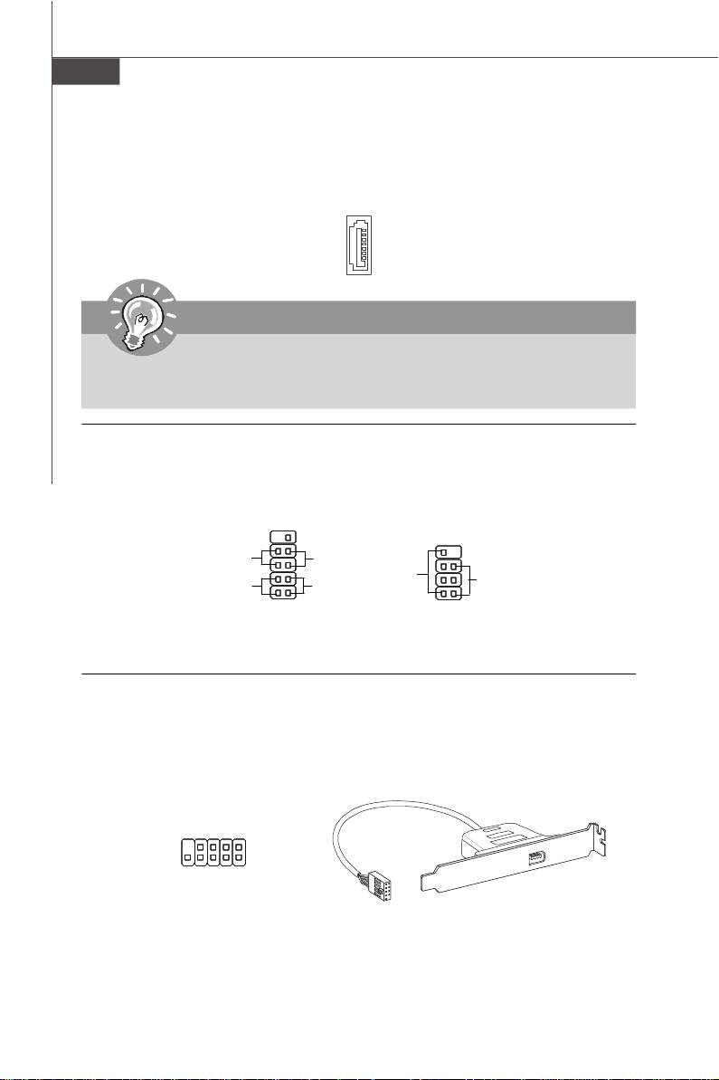
Front USB Connector (Yellow)
®
This connector, compliant with Intel
I/O Connectivity Design Guide, is ideal for con-
necting high-speed USB interface peripherals such as USB HDD, digital cameras, MP3
players, printers, modems and the like.
English
USB 2.0 Bracket
VCC
USB1-
USB1+
GND
USBOC
(Optional)
2
10
1
9
VCC
GND
USB0-
USB0+
Key (no pin)
Important
Note that the pins of VCC and GND must be connected correctly to avoid possible
damage.
Chassis Intrusion Connector
This connector connects to the chassis intrusion switch cable. If the chassis is opened,
the chassis intrusion mechanism will be activated. The system will record this status and
show a warning message on the screen. To clear the warning, you must enter the BIOS
utility and clear the record.
1
CINTRU
GND
Serial Port Connector
This connector is a 16550A high speed communication port that sends/receives 16
bytes FIFOs. You can attach a serial device.
SIN
DSR
CTS
2
10
1
9
RI
DCD
RTS
SOUT DTR
Ground
En-11
PDF 檔案使用 "pdfFactory" 試用版本建立 www.ahasoft.com.tw/FinePrint
MS-7528 Mainboard
CD-In Connector
This connector is provided for external audio input.
L
GND R
S/PDIF-Out Connector or S/PDIF-In Connector
This connector is used to connect S/PDIF (Sony & Philips Digital Interconnect Format)
interface for digital audio transmission.
GND
SPDIF_out
VCC
SPDIF_Out
SPDIF Bracket (Optional)
Front Panel Audio Connector (Azalia Spec)
®
This connector allows you to connect the front panel audio and is compliant with Intel
Front Panel I/O Connectivity Design Guide.
Ground
Presence#
MIC_JD
NC(No pin)
LINE out_JD
2
10
1
9
MIC _L
MIC _R
Front_JD
LINE out_R
LINE out_L
En-12
PDF 檔案使用 "pdfFactory" 試用版本建立 www.ahasoft.com.tw/FinePrint
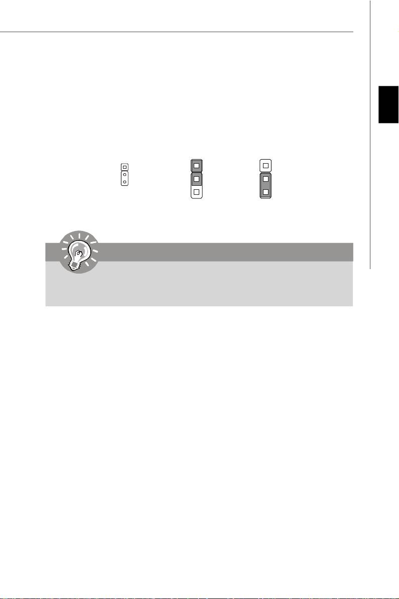
Clear CMOS Jumper
There is a CMOS RAM onboard that has a power supply from an external battery to keep
English
the data of system configuration. With the CMOS RAM, the system can automatically
boot OS every time it is turned on. If you want to clear the system configuration, set the
jumper to clear data.
1
1
1
Keep Data (default)
Clear Data
Important
You can clear CMOS by shorting 2-3 pin while the system is off. Then return to 1-
2 pin position. Avoid clearing the CMOS while the system is on; it will damage
the mainboard.
En-13
PDF 檔案使用 "pdfFactory" 試用版本建立 www.ahasoft.com.tw/FinePrint
MS-7528 Mainboard
Power Supply Attachment
Before inserting the power supply connector, always make sure that all components are
installed properly to ensure that no damage will be caused. All power connectors on
the mainbnoard have to connect to the ATX power supply and have to work together to
ensure stable operation of the mainboard.
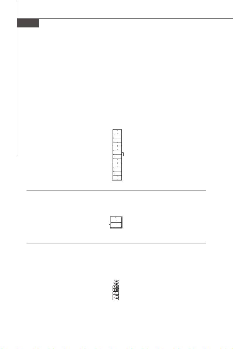
ATX 24-Pin Power Connector
This connector allows you to connect an ATX 24-pin power supply. To connect the ATX
24-pin power supply, make sure the plug of the power supply is inserted in the proper
orientation and the pins are aligned. Then push down the power supply firmly into the
connector.
You may use the 20-pin ATX power supply as you like. If you’d like to use the 20-pin ATX
power supply, please plug your power supply along with pin 1 & pin 13.
12
24
+3.3V
GND
+12V
+5V
+12V
+5V
5VSB
+5V
PWR OK
NC
GND
GND
+5V
GND
GND
GND
+5V
PS-ON#
GND
GND
+3.3V
-12V
+3.3V
+3.3V
1
13
ATX 12V Power Connector (2x2-Pin)
This 12V power connector is used to provide power to the CPU.
4 2
GND12V
12V
GND
3
1
TPM module Connector
This connector connects to a TPM (Trusted Platform Module) module (optional). Please
refer to the TPM security platform manual for more details and usages.
21
LCLK
3Vdual / 3V_STB
LRST#
VCC3
LAD0
SIRQ
LAD1
VCC5
LAD2
Key(no pin)
LAD3
GND
LFRAME#
GND
1413
En-14
PDF 檔案使用 "pdfFactory" 試用版本建立 www.ahasoft.com.tw/FinePrint
PCI (Peripheral Component Interconnect) Express Slot
The PCI Express slot supports the PCI Express interface expansion card.
The PCI Express x 16 supports up to 4.0 GB/s transfer rate.
English
The PCI Express x 1 supports up to 250 MB/s transfer rate.
Mazarine PCI Express x16 Slots support
PCI Express x 16 speed (PCI_E1)
White PCI Express x 1 Slots support
PCI Express x 1 speed (PCI_E2)
PCI (Peripheral Component Interconnect) Slot
The PCI slot supports LAN card, SCSI card, USB card, and other add-on cards that
comply with PCI specifications.
Important
When adding or removing expansion cards, make sure that you unplug the power
supply first. Meanwhile, read the documentation for the expansion card to configure
any necessary hardware or software settings for the expansion card, such as
jumpers, switches or BIOS configuration.
En-15
PDF 檔案使用 "pdfFactory" 試用版本建立 www.ahasoft.com.tw/FinePrint
MS-7528 Mainboard
Back Panel
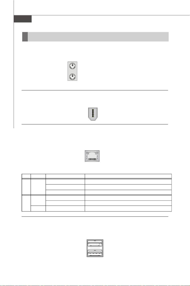
Mouse/Keyboard
®
®
The standard PS/2
mouse/keyboard DIN connector is for a PS/2
mouse/keyboard.
PS/2 Mouse connector (Green/ 6-pin female)
PS/2 Keyboard connector (Purple/ 6-pin female)
1394 Port
The IEEE1394 port on the back panel provides connection to IEEE1394 devices.
LAN
The standard RJ-45 LAN jack is for connection to the Local Area Network (LAN). You can
connect a network cable to it.
LED Color LED State Condition
Off LAN link is not established.
Left Orange On (steady state) LAN link is established.
On (brighter & pulsing) The computer is communicating with another computer on the LAN.
Green Off 10 Mbit/sec data rate is selected.
Right On 100 Mbit/sec data rate is selected.
Orange On 1000 Mbit/sec data rate is selected.
USB Port
The USB (Universal Serial Bus) port is for attaching USB devices such as keyboard,
mouse, or other USB-compatible devices.
En-16
PDF 檔案使用 "pdfFactory" 試用版本建立 www.ahasoft.com.tw/FinePrint
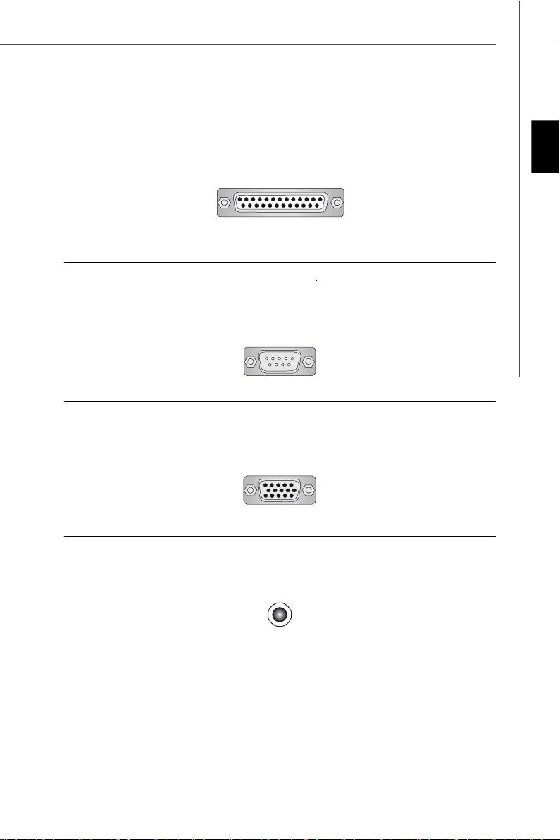
Parallel Port
A parallel port is a standard printer port that supports Enhanced Parallel Port (EPP) and
Extended Capabilities Parallel Port (ECP) mode.
English
13 1
(25-pin female connector)
1425
Serial Port
The serial port is a 16550A high speed communications port that sends/ receives 16
bytes FIFOs. You can attach a serial mouse or other serial devices directly to the
connector.
1 5
(9-Pin Male Connector)
6 9
VGA Port
The DB15-pin female connector is provided for monitor.
15
(15-Pin Female DIN Connector)
1115
Audio Port Connectors
These audio connectors are used for audio devices. You can differentiate the color of
the audio jacks for different audio sound effects.
Line-Out (Green) - Line Out, is a connector for speakers or headphones.
Line-In (Blue) - Line In / Side-Surround Out in 7.1 channel mode, is used for external
CD player, tape player or other audio devices.
MIC (Pink) - Mic In, is a connector for microphones.
CS-Out (Orange) - Center/ Subwoofer Out in 5.1/ 7.1 channel mode.
RS-Out (Black) - Rear-Surround Out in 4/ 5.1/ 7.1 channel mode.
SS-Out (Gray) - Side-Surround Out 7.1 channel mode.
En-17
PDF 檔案使用 "pdfFactory" 試用版本建立 www.ahasoft.com.tw/FinePrint

MS-7528 Mainboard
BIOS Setup
This chapter provides basic information on the BIOS Setup program and allows you to
configure the system for optimum use. You may need to run the Setup program when:
* An error message appears on the screen during the system booting up, and requests
you to run BIOS SETUP.
* You want to change the default settings for customized features.
Important
1.The items under each BIOS category described in this chapter are under con-
tinuous update for better system performance. Therefore, the description may
be slightly different from the latest BIOS and should be held for reference only.
2.Upon boot-up, the 1st line appearing after the memory count is the BIOS
version. It is usually in the format:
A7528IMS V1.0 010108 where:
1st digit refers to BIOS maker as A = AMI, W = AWARD, and P = PHOENIX.
2nd - 5th digit refers to the model number.
6th refers to the Chipset vender as A = ATi, I = Intel, V = VIA, N = Nvidia, U = ULi.
7th - 8th digit refers to the customer as MS = all standard customers.
V1.0 refers to the BIOS version.
010108 refers to the date this BIOS was released.
En-18
PDF 檔案使用 "pdfFactory" 試用版本建立 www.ahasoft.com.tw/FinePrint
Entering Setup
Power on the computer and the system will start POST (Power On Self Test) process.
When the message below appears on the screen, press <DEL> key to enter Setup.
Press DEL to enter SETUP
English
If the message disappears before you respond and you still wish to enter Setup, restart
the system by turning it OFF and On or pressing the RESET button. You may also restart
the system by simultaneously pressing <Ctrl>, <Alt>, and <Delete> keys.
Getting Help
After entering the Setup menu, the first menu you will see is the Main Menu.
Main Menu
The main menu lists the setup functions you can make changes to. You can use the
arrow keys (↑↓ ) to select the item. The on-line description of the highlighted setup
function is displayed at the bottom of the screen.
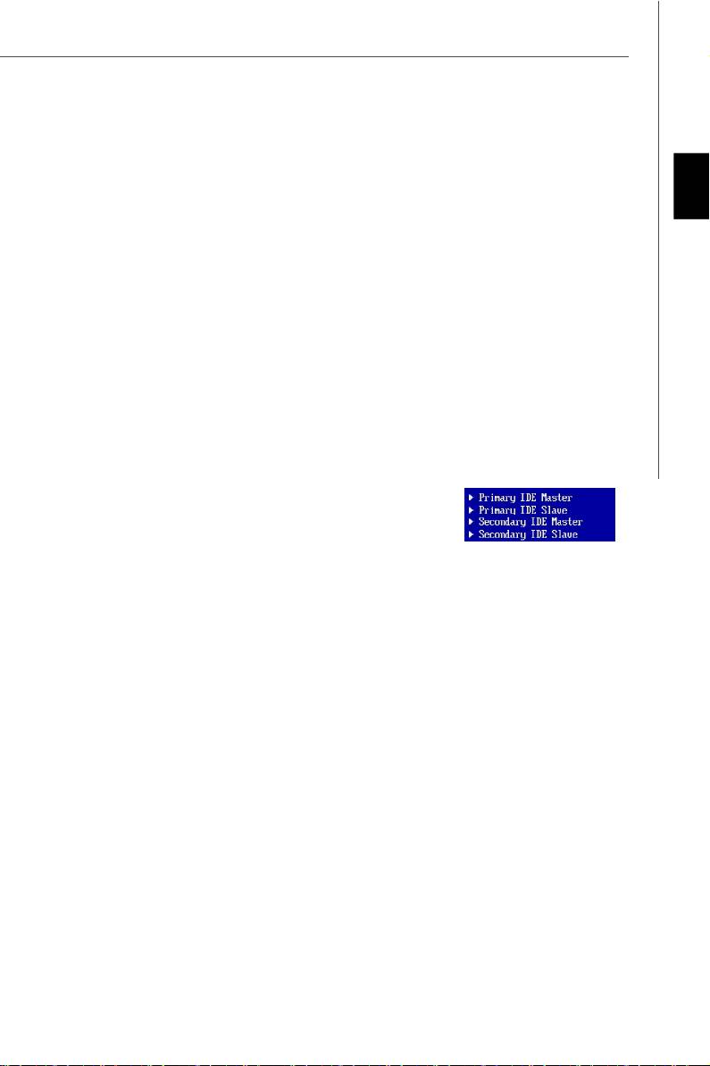
Sub-Menu
If you find a right pointer symbol (as shown in the right view)
appears to the left of certain fields that means a sub-menu
containing additional options can be launched from this
field. You can use control keys (↑↓ ) to highlight the field
and press <Enter> to call up the sub-menu. Then you can
use the control keys to enter values and move from field to field within a sub-menu. If
you want to return to the main menu, just press <Esc >.
General Help <F1>
The BIOS setup program provides a General Help screen. You can call up this screen
from any menu by simply pressing <F1>. The Help screen lists the appropriate keys to
use and the possible selections for the highlighted item. Press <Esc> to exit the Help
screen.
En-19
PDF 檔案使用 "pdfFactory" 試用版本建立 www.ahasoft.com.tw/FinePrint
MS-7528 Mainboard
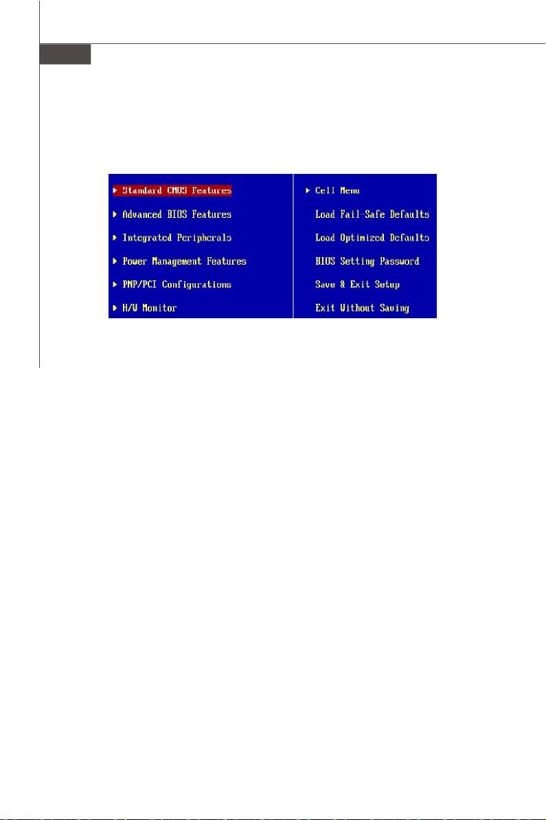
The Main Menu
®
®
Once you enter AMI
or AWARD
BIOS CMOS Setup Utility, the Main Menu will appear
on the screen. The Main Menu allows you to select from ten setup functions and two exit
choices. Use arrow keys to select among the items and press <Enter> to accept or enter
the sub-menu.
Standard CMOS Features
Use this menu for basic system configurations, such as time, date etc.
Advanced BIOS Features
Use this menu to setup the items of special enhanced features.
Integrated Peripherals
Use this menu to specify your settings for integrated peripherals.
Power Management Features
Use this menu to specify your settings for power management.
PNP/PCI Configurations
This entry appears if your system supports PnP/PCI.
H/W Monitor
This entry shows your PC health status.
Cell Menu
Use this menu to specify your settings for fequency/voltage control and overclocking.
Load Fail-Safe Defaults
Use this menu to load the default values set by the BIOS vendor for stable system
performance.
Load Optimized Defaults
Use this menu to load the default values set by the mainboard manufacturer specifically
for optimal performance of themainboard.
BIOS Setting Password
Use this menu to set the Password.
Save & Exit Setup
Save changes to CMOS and exit setup.
Exit Without Saving
Abandon all changes and exit setup.
En-20
PDF 檔案使用 "pdfFactory" 試用版本建立 www.ahasoft.com.tw/FinePrint
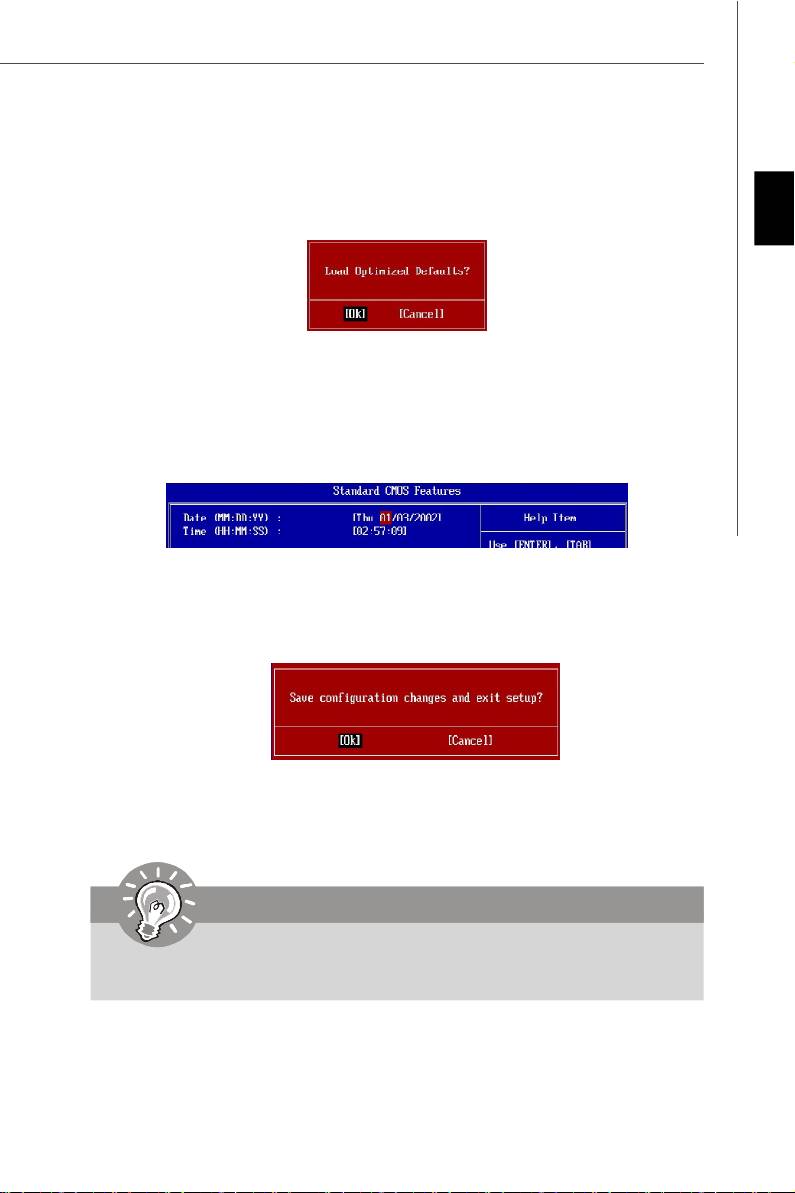
When enter the BIOS Setup utility, follow the processes below for general use.
1. Load Optimized Defaults : Use control keys (↑↓ ) to highlight the Load Optimized
Defaults field and press <Enter> , a message as below appears:
English
Press [Ok] to load the default settings for optimal system performance.
2. Setup Date/ Time : Select the Standard CMOS Features and press <Enter> to enter
the Standard CMOS Features-menu. Adjust the Date, Time fields.
3. Save & Exit Setup : Use control keys (↑↓ ) to highlight the Save & Exit Setup field
and press <Enter> , a message as below appears:
Press [Ok] to save the configurations and exit BIOS Setup utility.
Important
The configuration above are for general use only. If you need the detailed
settings of BIOS, please see the manual in English version on MSI website.
En-21
PDF 檔案使用 "pdfFactory" 試用版本建立 www.ahasoft.com.tw/FinePrint

MS-7528 Mainboard
Software Information
Take out the Driver/Utility CD that is included in the mainboard package, and place it
into the CD-ROM driver. The installation will auto-run, simply click the driver or utiltiy
and follow the pop-up screen to complete the installation. The Driver/Utility CD con-
tains the:
Driver menu - The Driver menu shows the available drivers. Install the driver by your
desire and to activate the device.
Utility menu - The Utility menu shows the software applications that the mainboard
supports.
WebSite menu- The WebSite menu shows the necessary websites.
Important
Please visit the MSI website to get the latest drivers and BIOS for better system
performance.
En-22
PDF 檔案使用 "pdfFactory" 試用版本建立 www.ahasoft.com.tw/FinePrint
Оглавление
- G31M3 User’s Guide English
- G31M3 Benutzerhandbuch
- G31M3 Guide d’Utilisation
- G31M3 Руководство пользователя
