MSI a88xm-e35: инструкция
Раздел: Компьютерная техника, комплектующие, аксессуары
Тип: Материнская Плата
Характеристики, спецификации
Инструкция к Материнской Плате MSI a88xm-e35
Copyright Notice
The material in this document is the intellectual property of MICRO-STAR
INTERNATIONAL. We take every care in the preparation of this document, but no
guarantee is given as to the correctness of its contents. Our products are under
continual improvement and we reserve the right to make changes without notice.
Preface
Trademarks
All trademarks in this manual are properties of their respective owners.
®
■
MSI
is registered trademark of Micro-Star Int’l Co.,Ltd.
®
■
NVIDIA
is registered trademark of NVIDIA Corporation.
®
■
ATI
is registered trademark of AMD Corporation.
®
■
AMD
is registered trademarks of AMD Corporation.
®
■
Intel
is registered trademarks of Intel Corporation.
®
■
Windows
is registered trademarks of Microsoft Corporation.
®
■
AMI
is registered trademark of American Megatrends Inc.
®
■
Award
is a registered trademark of Phoenix Technologies Ltd.
®
■
Sound Blaster
is registered trademark of Creative Technology Ltd.
®
■
Realtek
is registered trademark of Realtek Semiconductor Corporation.
®
■
JMicron
is registered trademark of JMicron Technology Corporation.
®
■
Netware
is registered trademark of Novell, Inc.
®
■
Lucid
is trademark of LucidLogix Technologies, Ltd.
®
■
VIA
is registered trademark of VIA Technologies, Inc.
®
■
ASMedia
is registered trademark of ASMedia Technology Inc.
■
iPad, iPhone, and iPod are trademarks of Apple Inc.
■
Qualcomm Atheros and Killer are trademarks of Qualcomm Atheros Inc.
Revision History
Revision Revision History Date
V6.0 First release 203/0
G52-772XS
Safety Instructions
Preface
■
Always read the safety instructions carefully.
■
Keep this User’s Manual for future reference.
■
Keep this equipment away from humidity.
■
Lay this equipment on a reliable at surface before setting it up.
■
The openings on the enclosure are for air convection hence protects the
equipment from overheating. DO NOT COVER THE OPENINGS.
■
Make sure the voltage of the power source is at 0/220V before connecting the
equipment to the power inlet.
■
Place the power cord such a way that people can not step on it. Do not place
anything over the power cord.
■
Always Unplug the Power Cord before inserting any add-on card or module.
■
All cautions and warnings on the equipment should be noted.
■
Never pour any liquid into the opening that can cause damage or cause electrical
shock.
■
If any of the following situations arises, get the equipment checked by service
personnel:
◯
The power cord or plug is damaged.
◯
Liquid has penetrated into the equipment.
◯
The equipment has been exposed to moisture.
◯
The equipment does not work well or you can not get it work according to
User’s Manual.
◯
The equipment has been dropped and damaged.
◯
The equipment has obvious sign of breakage.
o
■
DO NOT LEAVE THIS EQUIPMENT IN AN ENVIRONMENT ABOVE 60
C
o
(40
F), IT MAY DAMAGE THE EQUIPMENT.
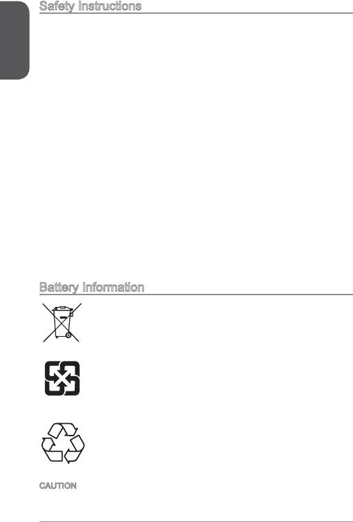
Battery Information
European Union:
Batteries, battery packs, and accumulators should not be disposed
of as unsorted household waste. Please use the public collection
system to return, recycle, or treat them in compliance with the local
regulations.
Taiwan:
For better environmental protection, waste batteries should be
collected separately for recycling or special disposal.
廢電池請回收
California, USA:
The button cell battery may contain perchlorate material and requires
special handling when recycled or disposed of in California.
For further information please visit:
http://www.dtsc.ca.gov/hazardouswaste/perchlorate/
CAUTION: There is a risk of explosion, if battery is incorrectly replaced.
Replace only with the same or equivalent type recommended by the manufacturer.
2
FCC-B Radio Frequency Interference Statement
This equipment has been tested and found to comply with the limits for a Class
B digital device, pursuant to Part 5 of the FCC Rules. These limits are designed
to provide reasonable protection against harmful interference in a residential
installation. This equipment generates, uses and can radiate radio frequency
Preface
energy and, if not installed and used in accordance with the instructions, may cause
harmful interference to radio communications. However, there is no guarantee that
interference will not occur in a particular installation. If this equipment does cause
harmful interference to radio or television reception, which can be determined
by turning the equipment o and on, the user is encouraged to try to correct the
interference by one or more of the measures listed below.
◯
Reorient or relocate the receiving antenna.
◯
Increase the separation between the equipment and receiver.
◯
Connect the equipment into an outlet on a circuit dierent from that to which
the receiver is connected.
◯
Consult the dealer or an experienced radio/television technician for help.
Notice
The changes or modications not expressly approved by the party responsible for
compliance could void the user’s authority to operate the equipment.
Notice 2
Shielded interface cables and A.C. power cord, if any, must be used in order to
comply with the emission limits.
VOIR LA NOTICE D’INSTALLATION AVANT DE RACCORDER AU RESEAU.
Micro-Star International
MS-772
This device complies with Part 5 of the FCC Rules. Operation is subject to the
following two conditions:
)
this device may not cause harmful interference, and
2)
this device must accept any interference received, including interference that
may cause undesired operation.
CE Conformity
Hereby, Micro-Star International CO., LTD declares that this device is
in compliance with the essential safety requirements and other relevant
provisions set out in the European Directive.
3
Radiation Exposure Statement
Preface
This equipment complies with FCC radiation exposure limits set forth for an
uncontrolled environment. This equipment and its antenna should be installed and
operated with minimum distance 20 cm between the radiator and your body. This
equipment and its antenna must not be co-located or operating in conjunction with
any other antenna or transmitter.
European Community Compliance Statement
The equipment complies with the RF Exposure Requirement 999/59/EC, Council
Recommendation of 2 July 999 on the limitation of exposure of the general public
to electromagnetic elds (0–300GHz). This wireless device complies with the R&TTE
Directive.
Taiwan Wireless Statements
無線設備警告聲明
經型式認證合格之低功率射頻電機,非經許可,公司、商號或使用者均不得擅自變更
頻率、加大功率或變更原設計之特性及功能。
低功率射頻電機之使用不得影響飛航安全及干擾合法通信;經發現有干擾現象時,應
立即停用,並改善至無干擾時方得繼續使用。前項合法通信,指依電信法規定作業之
無線電通信。低功率射頻電機須忍受合法通信或工業、科學及醫療用電波輻射性電機
設備之干擾。
警告使用者:這是甲類資訊產品,在居住的環境中使用時,可能會造成無線電干擾,在
這種情況下,使用者會被要求採取某些適當的對策。
Japan VCCI Class B Statement
クラス B 情報技術装置
この装置は、情報技術装置等電波障害自主規制協議会(VCCI)の基準に基づくクラ
スB情報技術装置です。この装置が家庭内でラジオやテレビジョン受信機に近接して
使われると、受信障害を引き起こすことがあります。取扱説明書にしたがって正し
い取り扱いをしてください。
Korea Warning Statements
당해 무선설비는 운용중 전파혼신 가능성이 있음
Chemical Substances Information
In compliance with chemical substances regulations, such as the EU REACH
Regulation (Regulation EC No. 907/2006 of the European Parliament and the
Council), MSI provides the information of chemical substances in products at:
http://www.msi.com/html/popup/csr/evmtprtt_pcm.html
4
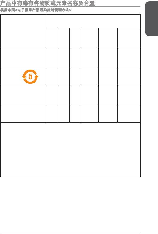
产品中有毒有害物质或元素名称及含量
根据中国<电子信息产品污染控制管理办法>
有毒有害物质或元素
Preface
部件名称
铅
汞
镉
六价铬
多溴联苯
多溴二苯醚
(Pb)
(Hg)
(Cd)
(Cr6+)
(PBB)
(PBDE)
印刷电路板组件* ☓ 〇 〇 〇 〇 〇
电池**
☓ 〇 〇 〇 〇 〇
外部信号连接头 ☓ 〇 〇 〇 〇 〇
线材 ☓ 〇 〇 〇 〇 〇
〇: 表示该有毒有害物质在该部件所有均质材料中的含量均在SJ/T363-2006标
准规定的限量要求下。
☓: 表示该有毒有害物质至少在该部件的某一均质材料中的含量超出SJ/T363-
2006标准规定的限量要求,但所有部件都符合欧盟RoHS要求。
* 印刷电路板组件: 包括印刷电路板及其构成的零部件。
** 电池本体上如有环保使用期限标识,以本体标识为主。
■
上述有毒有害物质或元素清单会依型号之部件差异而有所增减。
■
產品部件本体上如有环保使用期限标识,以本体标识为主。
5
WEEE Statement
Preface
WEEE (Waste Electrical and Electronic Equipment)
ENGLISH
To protect the global environment and as an environmentalist, MSI must
remind you that...
Under the European Union (“EU”) Directive on Waste Electrical and
Electronic Equipment, Directive 2002/96/EC, which takes eect on August 3, 2005,
products of “electrical and electronic equipment” cannot be discarded as municipal
wastes anymore, and manufacturers of covered electronic equipment will be
obligated to take back such products at the end of their useful life. MSI will comply
with the product take back requirements at the end of life of MSI-branded products
that are sold into the EU. You can return these products to local collection points.
DEUTSCH
Hinweis von MSI zur Erhaltung und Schutz unserer Umwelt
Gemäß der Richtlinie 2002/96/EG über Elektro- und Elektronik-Altgeräte dürfen
Elektro- und Elektronik-Altgeräte nicht mehr als kommunale Abfälle entsorgt werden.
MSI hat europaweit verschiedene Sammel- und Recyclingunternehmen beauftragt,
die in die Europäische Union in Verkehr gebrachten Produkte, am Ende seines
Lebenszyklus zurückzunehmen. Bitte entsorgen Sie dieses Produkt zum gegebenen
Zeitpunkt ausschliesslich an einer lokalen Altgerätesammelstelle in Ihrer Nähe.
FRANÇAIS
En tant qu’écologiste et an de protéger l’environnement, MSI tient à rappeler ceci...
Au sujet de la directive européenne (EU) relative aux déchets des équipement
électriques et électroniques, directive 2002/96/EC, prenant eet le 3 août 2005,
que les produits électriques et électroniques ne peuvent être déposés dans les
décharges ou tout simplement mis à la poubelle. Les fabricants de ces équipements
seront obligés de récupérer certains produits en n de vie. MSI prendra en compte
cette exigence relative au retour des produits en n de vie au sein de la communauté
européenne. Par conséquent vous pouvez retourner localement ces matériels dans
les points de collecte.
РУССКИЙ
Компания MSI предпринимает активные действия по защите окружающей
среды, поэтому напоминаем вам, что....
В соответствии с директивой Европейского Союза (ЕС) по предотвращению
загрязнения окружающей среды использованным электрическим и электронным
оборудованием (директива WEEE 2002/96/EC), вступающей в силу 3
августа 2005 года, изделия, относящиеся к электрическому и электронному
оборудованию, не могут рассматриваться как бытовой мусор, поэтому
производители вышеперечисленного электронного оборудования обязаны
принимать его для переработки по окончании срока службы. MSI обязуется
соблюдать требования по приему продукции, проданной под маркой MSI на
территории EC, в переработку по окончании срока службы. Вы можете вернуть
эти изделия в специализированные пункты приема.
6
ESPAÑOL
MSI como empresa comprometida con la protección del medio ambiente,
recomienda:
Bajo la directiva 2002/96/EC de la Unión Europea en materia de desechos y/o
equipos electrónicos, con fecha de rigor desde el 3 de agosto de 2005, los
Preface
productos clasicados como “eléctricos y equipos electrónicos” no pueden ser
depositados en los contenedores habituales de su municipio, los fabricantes de
equipos electrónicos, están obligados a hacerse cargo de dichos productos al
termino de su período de vida. MSI estará comprometido con los términos de
recogida de sus productos vendidos en la Unión Europea al nal de su periodo de
vida. Usted debe depositar estos productos en el punto limpio establecido por el
ayuntamiento de su localidad o entregar a una empresa autorizada para la recogida
de estos residuos.
NEDERLANDS
Om het milieu te beschermen, wil MSI u eraan herinneren dat….
De richtlijn van de Europese Unie (EU) met betrekking tot Vervuiling van Electrische
en Electronische producten (2002/96/EC), die op 3 Augustus 2005 in zal gaan
kunnen niet meer beschouwd worden als vervuiling. Fabrikanten van dit soort
producten worden verplicht om producten retour te nemen aan het eind van hun
levenscyclus. MSI zal overeenkomstig de richtlijn handelen voor de producten
die de merknaam MSI dragen en verkocht zijn in de EU. Deze goederen kunnen
geretourneerd worden op lokale inzamelingspunten.
SRPSKI
Da bi zaštitili prirodnu sredinu, i kao preduzeće koje vodi računa o okolini i prirodnoj
sredini, MSI mora da vas podesti da…
Po Direktivi Evropske unije (“EU”) o odbačenoj ekektronskoj i električnoj opremi,
Direktiva 2002/96/EC, koja stupa na snagu od 3. Avgusta 2005, proizvodi koji
spadaju pod “elektronsku i električnu opremu” ne mogu više biti odbačeni kao običan
otpad i proizvođači ove opreme biće prinuđeni da uzmu natrag ove proizvode na
kraju njihovog uobičajenog veka trajanja. MSI će poštovati zahtev o preuzimanju
ovakvih proizvoda kojima je istekao vek trajanja, koji imaju MSI oznaku i koji su
prodati u EU. Ove proizvode možete vratiti na lokalnim mestima za prikupljanje.
POLSKI
Aby chronić nasze środowisko naturalne oraz jako rma dbająca o ekologię, MSI
przypomina, że...
Zgodnie z Dyrektywą Unii Europejskiej (“UE”) dotyczącą odpadów produktów
elektrycznych i elektronicznych (Dyrektywa 2002/96/EC), która wchodzi w życie 3
sierpnia 2005, tzw. “produkty oraz wyposażenie elektryczne i elektroniczne “ nie
mogą być traktowane jako śmieci komunalne, tak więc producenci tych produktów
będą zobowiązani do odbierania ich w momencie gdy produkt jest wycofywany z
użycia. MSI wypełni wymagania UE, przyjmując produkty (sprzedawane na terenie
Unii Europejskiej) wycofywane z użycia. Produkty MSI będzie można zwracać w
wyznaczonych punktach zbiorczych.
7
TÜRKÇE
Preface
Çevreci özelliğiyle bilinen MSI dünyada çevreyi korumak için hatırlatır:
Avrupa Birliği (AB) Kararnamesi Elektrik ve Elektronik Malzeme Atığı, 2002/96/EC
Kararnamesi altında 3 Ağustos 2005 tarihinden itibaren geçerli olmak üzere,
elektrikli ve elektronik malzemeler diğer atıklar gibi çöpe atılamayacak ve bu
elektonik cihazların üreticileri, cihazların kullanım süreleri bittikten sonra ürünleri geri
toplamakla yükümlü olacaktır. Avrupa Birliği’ne satılan MSI markalı ürünlerin kullanım
süreleri bittiğinde MSI ürünlerin geri alınması isteği ile işbirliği içerisinde olacaktır.
Ürünlerinizi yerel toplama noktalarına bırakabilirsiniz.
ČESKY
Záleží nám na ochraně životního prostředí - společnost MSI upozorňuje...
Podle směrnice Evropské unie (“EU”) o likvidaci elektrických a elektronických
výrobků 2002/96/EC platné od 3. srpna 2005 je zakázáno likvidovat “elektrické
a elektronické výrobky” v běžném komunálním odpadu a výrobci elektronických
výrobků, na které se tato směrnice vztahuje, budou povinni odebírat takové výrobky
zpět po skončení jejich životnosti. Společnost MSI splní požadavky na odebírání
výrobků značky MSI, prodávaných v zemích EU, po skončení jejich životnosti. Tyto
výrobky můžete odevzdat v místních sběrnách.
MAGYAR
Annak érdekében, hogy környezetünket megvédjük, illetve környezetvédőként
fellépve az MSI emlékezteti Önt, hogy ...
Az Európai Unió („EU”) 2005. augusztus 3-án hatályba lépő, az elektromos
és elektronikus berendezések hulladékairól szóló 2002/96/EK irányelve szerint
az elektromos és elektronikus berendezések többé nem kezelhetőek lakossági
hulladékként, és az ilyen elektronikus berendezések gyártói kötelessé válnak az
ilyen termékek visszavételére azok hasznos élettartama végén. Az MSI betartja
a termékvisszavétellel kapcsolatos követelményeket az MSI márkanév alatt az
EU-n belül értékesített termékek esetében, azok élettartamának végén. Az ilyen
termékeket a legközelebbi gyűjtőhelyre viheti.
ITALIANO
Per proteggere l’ambiente, MSI, da sempre amica della natura, ti ricorda che….
In base alla Direttiva dell’Unione Europea (EU) sullo Smaltimento dei Materiali
Elettrici ed Elettronici, Direttiva 2002/96/EC in vigore dal 3 Agosto 2005, prodotti
appartenenti alla categoria dei Materiali Elettrici ed Elettronici non possono più
essere eliminati come riuti municipali: i produttori di detti materiali saranno obbligati
a ritirare ogni prodotto alla ne del suo ciclo di vita. MSI si adeguerà a tale Direttiva
ritirando tutti i prodotti marchiati MSI che sono stati venduti all’interno dell’Unione
Europea alla ne del loro ciclo di vita. È possibile portare i prodotti nel più vicino
punto di raccolta

Contents
English ......................................................................................
Motherboard Specications ....................................................................................2
Back Panel ..............................................................................................................5
Preface
APU & Heatsink Installation ....................................................................................6
Memory Installation .................................................................................................
Internal Connectors.................................................................................................9
BIOS Setup .............................................................................................................27
한국어 .......................................................................................33
메인보드 사양 .........................................................................................................34
후면 패널 .................................................................................................................37
APU 및 히트싱크 설치 ............................................................................................3
메모리 설치 .............................................................................................................40
내장 커넥터 .............................................................................................................4
BIOS 설정 ...............................................................................................................49
Français ....................................................................................55
Spécications ..........................................................................................................56
Panneau Arrière ......................................................................................................59
Installation d'APU et son ventilateur .......................................................................60
Installation de mémoire ...........................................................................................62
Connecteurs internes ..............................................................................................63
Conguration BIOS .................................................................................................7
Deutsch ....................................................................................77
Spezikationen........................................................................................................7
Rücktafel-Übersicht.................................................................................................
APU & Kühlkörper Einbau.......................................................................................2
Speicher ..................................................................................................................4
Interne Anschlüsse .................................................................................................5
BIOS Setup .............................................................................................................93
Русский ....................................................................................99
Характеристики материнской платы..................................................................00
Задняя панель .....................................................................................................03
Установка APU и радиатора ...............................................................................04
Установка памяти ................................................................................................06
Внутренние разъемы ..........................................................................................07
Настройка BIOS ...................................................................................................5
简体中文 .................................................................................2
主板规格 ................................................................................................................22
后置面板 ................................................................................................................25
APU 和风扇的安装 ................................................................................................26
9

内存安装 ................................................................................................................2
内部接口 ................................................................................................................29
Preface
BIOS 设置 .............................................................................................................37
繁體中文 .................................................................................43
主機板規格 ............................................................................................................44
背板 .......................................................................................................................47
安裝 APU 與散熱風扇 ...........................................................................................4
安裝記憶體 ............................................................................................................50
內建接頭 ................................................................................................................5
BIOS 設定 .............................................................................................................59
日本語 .....................................................................................65
マザーボードの仕様 ..............................................................................................66
I/Oパネル ..............................................................................................................69
APUおよびヒートシンクの装着 ...........................................................................70
メモリの装着 ........................................................................................................72
内部コネクター .....................................................................................................73
BIOSの設定 ...........................................................................................................
0
English
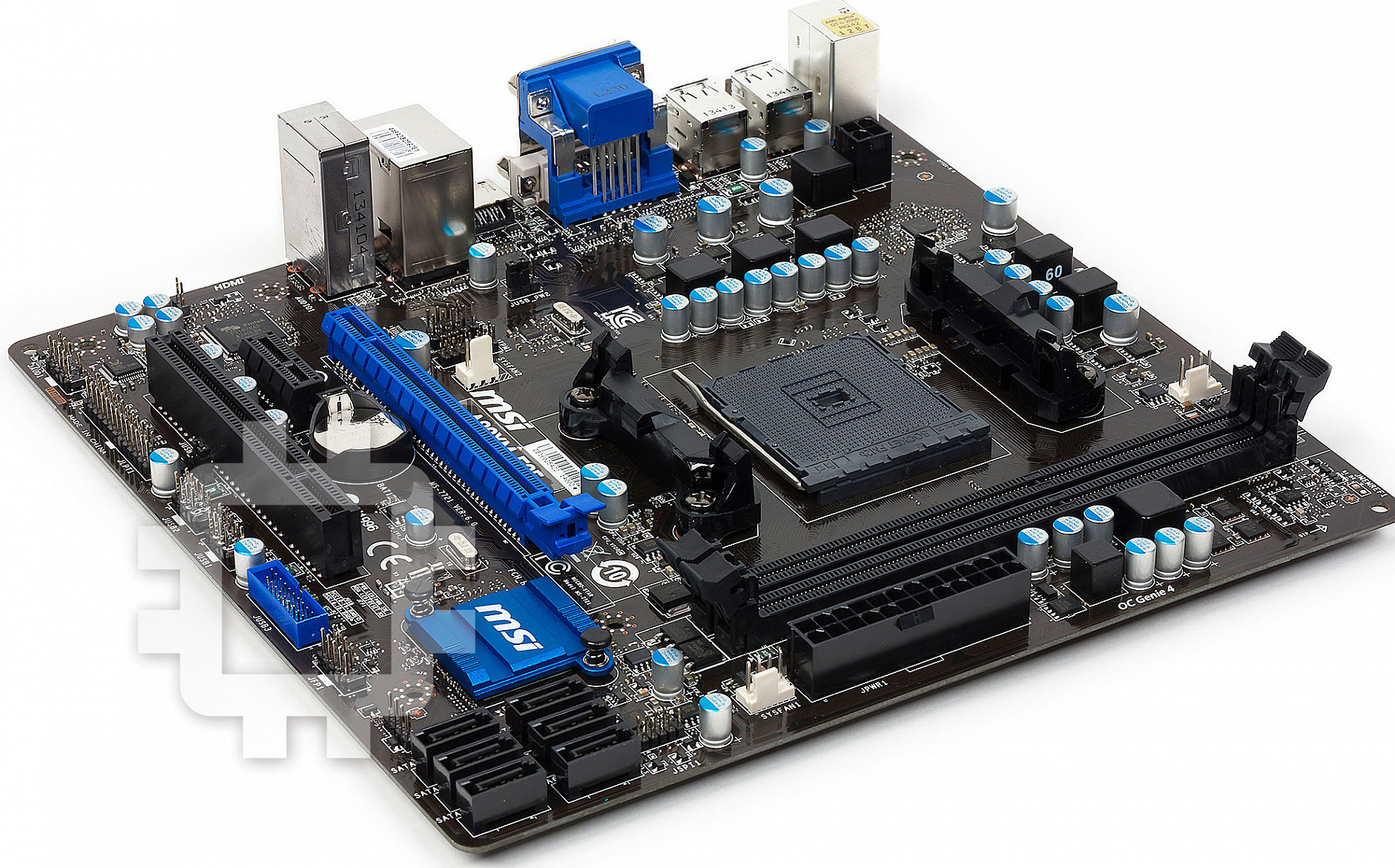
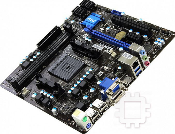
Thank you for choosing the AXM-E35/ A7M-E35/ A55M-E35 Series (MS-772
v6.X) Micro-ATX motherboard. The AXM-E35/ A7M-E35/ A55M-E35 Series
motherboards are based on AMD AX/ A7/ A55 chipset for optimal system
eciency. Designed to t the advanced AMD FM2+/ FM processor, the AXM-
E35/ A7M-E35/ A55M-E35 Series motherboards deliver a high performance and
professional desktop platform solution.
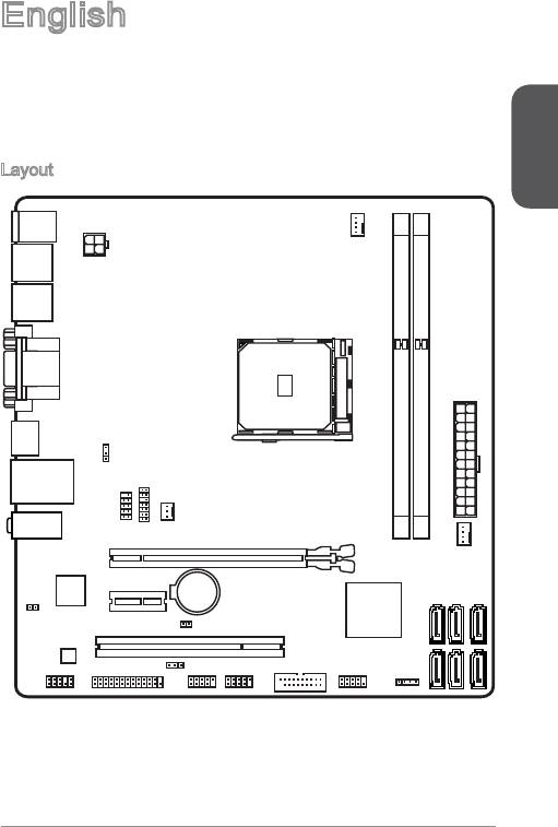
Layout
English
CPUFAN
Top : mouse po rt
Bottom : ke yb oard port
USB2.0 p or ts
JPWR2
USB2.0 p or ts
Top: VGA Port
Bottom: DV PortI-D
HDMI por t
JUSB_P W2
Top: LAN Jac k
Bottom : US B3 .0 ports
JTPM1
JCOM1
SYSFAN2
DIMM1
DIMM2
JPWR1
T:Line-I n
1
M:Line - Ou t
AN
B:MIC- In t
PCI_E1
SYSF
BAT1
PCI_E2
JCI1
4
5
6
JBAT1
TA
TA
TA
PCI1
SA
SA
SA
1
3
TA
2
JUSB_P W1
TA
JUSB3
JFP2
SA
TA
SA
SA
JAUD1
JLPT1
JUSB2
JUSB1
JFP1
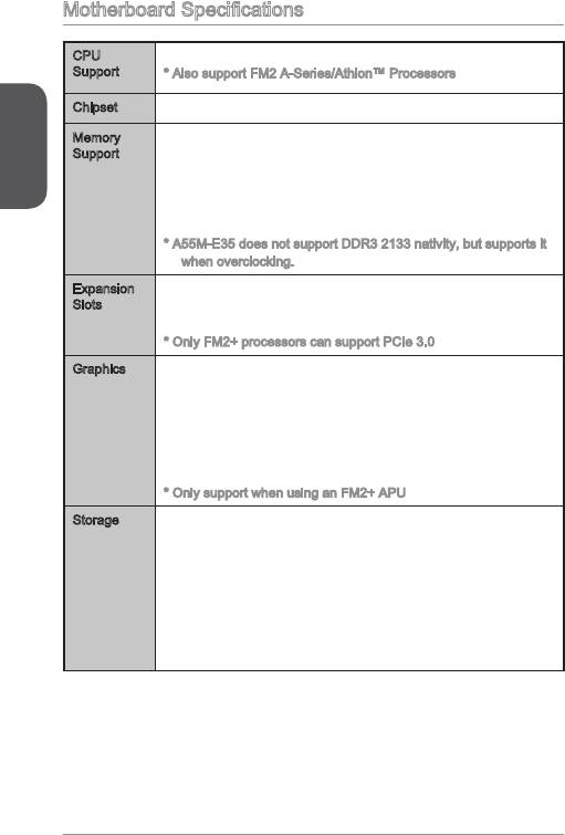
Motherboard Specications
CPU
■
AMD Socket FM2+ A-Series/Athlon™ Processors*
Support
* Also support FM2 A-Series/Athlon™ Processors
Chipset AMD AX/ A7/ A55■
English
Memory
■
2x DDR3 memory slots supporting up to 32GB
Support
■
Supports DDR3 233*/ 66/ 600/ 333 MHz
■
Dual channel memory architecture
■
Supports non-ECC, un-buered memory
■
Supports AMD Memory Prole (AMP)
■
Supports Extreme Memory Prole (XMP)
* A55M-E35 does not support DDR3 233 nativity, but supports it
when overclocking.
Expansion
■
x PCIe 3.0 x6 slot*
Slots
■
x PCIe 2.0 x slot
■
x PCI slot
* Only FM2+ processors can support PCIe 3.0
Graphics x VGA port, supporting a maximum resolution of 920x200
■
@ 60Hz, 24bpp
■
x DVI-D port, supporting a maximum resolution of
2560x600@60Hz, 24bpp/ 920x200 @ 60Hz, 24bpp
■
x HDMI port, supporting a maximum resolution of
4096x260@24Hz, 36bpp*/ 340x260@30Hz, 36bpp*/
920x200@20Hz, 36bpp and 920x200@60Hz, 36bpp
* Only support when using an FM2+ APU
Storage AXM-E35/ A7M-E35
■
-
AMD AX/ A7 Chipset
-
6x SATA 6Gb/s ports
-
Supports RAID 0, RAID, RAID 5 and RAID 0
■
A55M-E35
-
AMD A55 Chipset
-
6x SATA 3Gb/s ports
-
Supports RAID 0, RAID and RAID 0
2
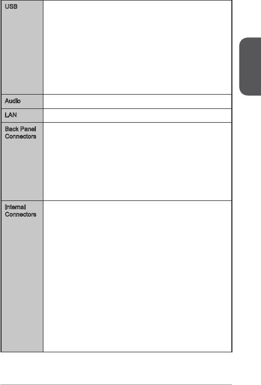
USB AXM-E35/ A7M-E35
■
-
AMD AX/ A7 Chipset
-
4x USB 3.0 ports (2 ports on the back panel, 2 ports
available through the internal USB connectors)
-
x USB 2.0 ports (4 ports on the back panel, 4 ports
available through the internal USB connectors)
■
A55M-E35
-
AMD A55 Chipset
-
0x USB 2.0 ports (6 ports on the back panel, 4 ports
English
available through the internal USB connectors)
®
Audio Realtek
ALC7 Codec■
®
LAN Realtek
RTLG Gigabit LAN controller■
Back Panel
■
x PS/2 keyboard port
Connectors
■
x PS/2 mouse port
■
4x USB 2.0 ports, 2x USB 3.0 ports (AXM-E35/ A7M-E35)
■
6x USB 2.0 ports (A55M-E35)
■
x VGA port
■
x DVI-D port
■
x HDMI port
■
x LAN (RJ45) port
■
3x audio jacks
Internal
■
x 24-pin ATX main power connector
Connectors
■
x 4-pin ATX 2V power connector
■
6x SATA 6Gb/s connectors (AXM-E35/ A7M-E35)
■
6x SATA 3Gb/s connectors (A55M-E35)
■
2x USB 2.0 connectors (supports additional 4 USB 2.0 ports)
■
x USB 3.0 connector (supports additional 2 USB 3.0 ports)
(AXM-E35/ A7M-E35)
■
x 4-pin CPU fan connector
■
x 4-pin system fan connector
■
x 3-pin system fan connector
■
x Front panel audio connector
■
2x System panel connectors
■
x Chassis Intrusion connector
■
x TPM module connector
■
x Serial port connector
■
x Parallel port connector
■
x Clear CMOS jumper
■
2x USB power jumpers
3
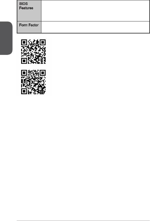
BIOS
■
64 Mb ash
Features
■
UEFI AMI BIOS
■
ACPI 5.0, PnP .0a, SM BIOS 2.7, DMI 2.0
■
Multi-language
Form Factor Micro-ATX Form Factor
■
English
■
.9 in. x .5 in. (22.6 cm x 2.6 cm)
For the latest information about CPU, please visit
http://www.msi.com/service/cpu-support/
For more information on compatible components, please
visit http://www.msi.com/service/test-report/
4
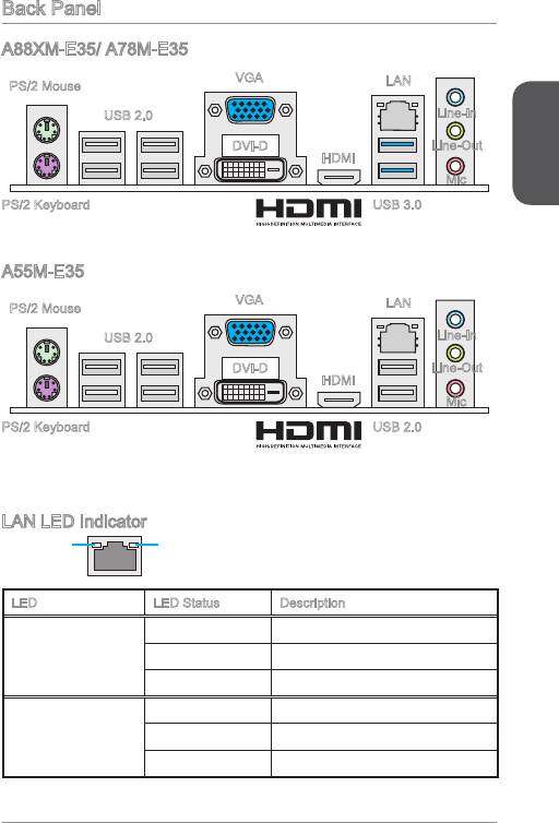
Back Panel
VGA
LAN
PS/2 Mouse
USB 2.0
Line-In
DVI-D
HDMI
English
PS/2 Keyboard USB 3.0
LAN LED Indicator
LINK/ACT
SPEED
LED
LED
LED LED Status Description
O No link
Link/ Activity LED
Yellow Linked
Blinking Data activity
O 0 Mbps connection
Speed LED
Green 00 Mbps connection
Orange Gbps connection
5
®
AXM-E35/ A7M-E35
Line-Out
Mic
VGA
LAN
PS/2 Mouse
USB 2.0
Line-In
DVI-D
HDMI
PS/2 Keyboard USB 2.0
®
A55M-E35
Line-Out
Mic
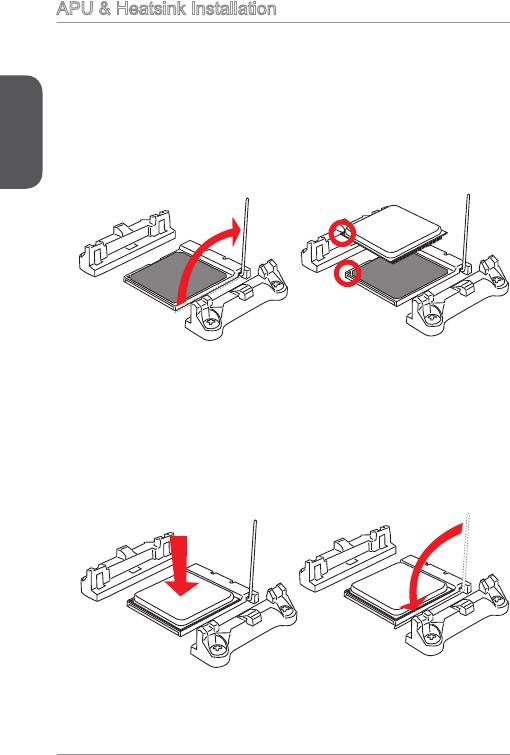
APU & Heatsink Installation
When installing a APU, always remember to install a APU heatsink. An APU heatsink
is necessary to prevent overheating and maintain system stability. Follow the steps
below to ensure correct APU and heatsink installation. Wrong installation can
damage both the APU and the motherboard.
English
. Pull the lever sideways away from the socket. Make sure to raise the lever up to
a 90-degree angle.
2. Look for the gold arrow of the APU. The gold arrow should point as shown in the
picture. The APU can only t in the correct orientation.
3. If the APU is correctly installed, the pins should be completely embedded into
the socket and can not be seen. Please note that any violation of the correct
installation procedures may cause permanent damages to your motherboard.
4. Press the APU down rmly into the socket and close the lever. As the APU is
likely to move while the lever is being closed, always close the lever with your
ngers pressing tightly on top of the APU to make sure the APU is properly and
completely embedded into the socket.
6
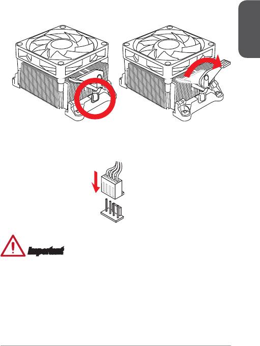
5. Locate the CPU fan connector on the motherboard.
6. Position the cooling set onto the retention mechanism. Hook one end of the clip
to hook rst.
7. Then press down the other end of the clip to fasten the cooling set on the top of
the retention mechanism. Locate the Fix Lever and lift up it.
. Fasten down the lever.
English
9. Attach the APU Fan cable to the APU fan connector on the motherboard.
Important
•
While disconnecting the Safety Hook from the xed bolt, it is necessary to keep an
eye on your ngers, because once the Safety Hook is disconnected from the xed
bolt, the xed lever will spring back instantly.
•
Conrm that the APU cooler has formed a tight seal with the APU before booting
your system.
•
Please refer to the documentation in the APU cooler package for more details
about APU cooler installation.
7
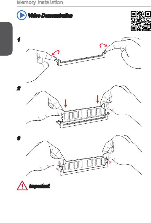
Memory Installation
Video Demonstration
Watch the video to learn how to install memories at the address below.
http://youtu.be/76yLtJaKlCQ
English
2
3
Important
•
DDR3 memory modules are not interchangeable with DDR2, and the DDR3
standard is not backward compatible. Always install DDR3 memory modules in
DDR3 DIMM slots.
•
To ensure system stability, memory modules must be of the same type and density
in Dual-Channel mode.
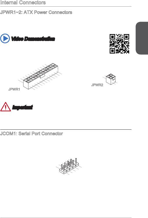
Internal Connectors
JPWR~2: ATX Power Connectors
These connectors allow you to connect an ATX power supply. To connect the ATX
power supply, align the power supply cable with the connector and rmly press the
cable into the connector. If done correctly, the clip on the power cable should be
hooked on the motherboard’s power connector.
Video Demonstration
English
Watch the video to learn how to install power supply connectors.
http://youtu.be/gkDYyR_3I4
9
12.+3. 3
11
10.+12 V
.+12V
9.5VSB
8.PW
V
7
6.+5
.Groun d
5
R O
4.+5
.Groun d
V
K
3
2.+3.3
.Groun d
V
1.+3.3
24.Gro und
V
23.+5
V
22.+5
21.+5
20.Res
V
19.Gro und
V
18.Gro und
V
17.Gro und
16.PS- ON
15.Gro und
14.-12 V
13.+3. 3
#
V
JPWR
1
.Ground
2
.Ground
3.+12V
4.+12V
JPWR2
Important
Make sure that all the power cables are securely connected to a proper ATX power
supply to ensure stable operation of the motherboard.
JCOM: Serial Port Connector
This connector is a 6550A high speed communication port that sends/receives 6
bytes FIFOs. You can attach a serial device.
1
0
8
.
.
N
6
C
o
.
D
T
P
4
S
S
i
.
n
2
D
R
.
T
S
R
I
N
9
.
7
R
.
R
I
5
3
.
G
T
.
S
1
S
r
o
.
D
O
u
C
U
n
T
d
D
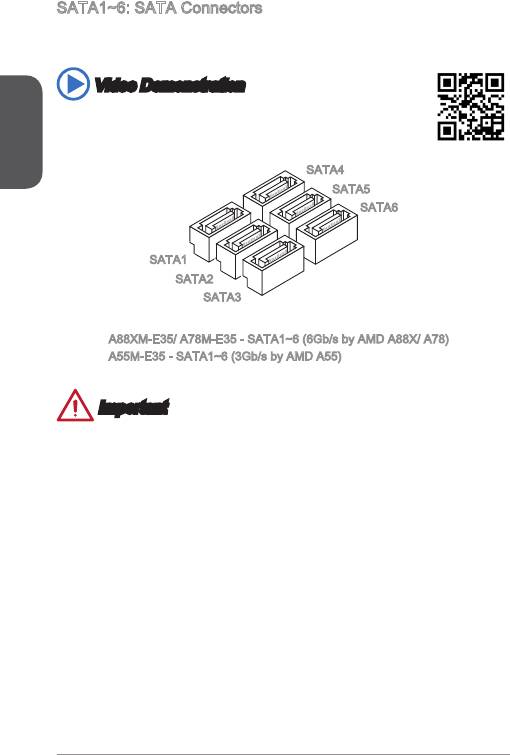
SATA~6: SATA Connectors
This connector is a high-speed SATA interface port. Each connector can connect to
one SATA device. SATA devices include disk drives (HDD), solid state drives (SSD),
and optical drives (CD/ DVD/ Blu-Ray).
Video Demonstration
English
Watch the video to learn how to Install SATA HDD.
http://youtu.be/RZsMpqxythc
SATA4
SATA5
SATA6
SATA
SATA2
SATA3
AXM-E35/ A7M-E35 - SATA~6 (6Gb/s by AMD AX/ A7)
A55M-E35 - SATA~6 (3Gb/s by AMD A55)
Important
•
Many SATA devices also need a power cable from the power supply. Such devices
include disk drives (HDD), solid state drives (SSD), and optical drives (CD / DVD /
Blu-Ray). Please refer to the device’s manual for further information.
•
Many computer cases also require that large SATA devices, such as HDDs, SSDs,
and optical drives, be screwed down into the case. Refer to the manual that came
with your computer case or your SATA device for further installation instructions.
•
Please do not fold the SATA cable at a 90-degree angle. Data loss may result
during transmission otherwise.
•
SATA cables have identical plugs on either sides of the cable. However, it is
recommended that the at connector be connected to the motherboard for space
saving purposes.
20
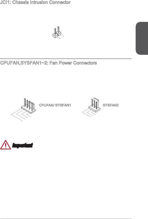
JCI: Chassis Intrusion Connector
This connector connects to the chassis intrusion switch cable. If the computer case
is opened, the chassis intrusion mechanism will be activated. The system will record
this intrusion and a warning message will ash on screen. To clear the warning, you
must enter the BIOS utility and clear the record.
English
2
1
.
2
G
.
C
r
o
I
u
N
n
T
d
R
U
CPUFAN,SYSFAN~2: Fan Power Connectors
The fan power connectors support system cooling fans with +2V. If the motherboard
has a System Hardware Monitor chipset on-board, you must use a specially designed
fan with a speed sensor to take advantage of the CPU fan control. Remember to
connect all system fans. Some system fans may not connect to the motherboard and
will instead connect to the power supply directly. A system fan can be plugged into
any available system fan connector.
1
2.+12V
.Ground
3.Sens
4.Speed
e
C
ontro
l
1
2.+ 12V
.Gr ound
3.N o
Us
e
CPUFAN/ SYSFAN SYSFAN2
Important
•
Please refer to your processor’s ocial website or consult your vendor to nd
recommended CPU heatsink.
•
These connectors support Smart Fan Control with liner mode. The Command
Center utility can be installed to automatically control the fan speeds according to
the CPU’s and system’s temperature.
•
If there are not enough ports on the motherboard to connect all system fans,
adapters are available to connect a fan directly to a power supply.
•
Before rst boot up, ensure that there are no cables impeding any fan blades.
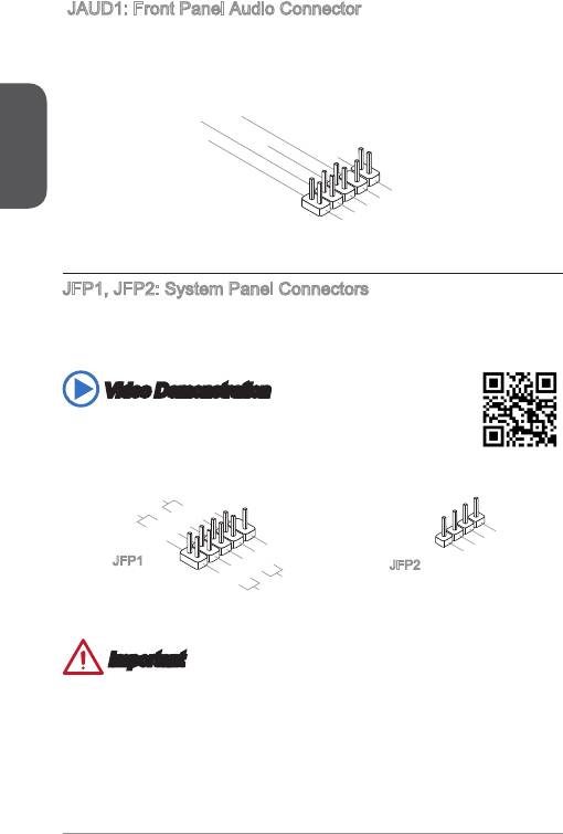
JAUD: Front Panel Audio Connector
This connector allows you to connect the front audio panel located on your computer
case.
English
22
10.Head
8.No
6.MI
4.NC
Pi
P
2
C D
n
hone
.Ground
etection
Detection
9.Head
7.SENSE_SEN
5.Head
3.MI
P
1.MI
hone
C R
P
C L
hone
L
D
R
JFP, JFP2: System Panel Connectors
These connectors connect to the front panel switches and LEDs. When installing the
front panel connectors, please use the optional M-Connector to simplify installation.
Plug all the wires from the computer case into the M-Connector and then plug the
M-Connector into the motherboard.
Video Demonstration
Watch the video to learn how to Install front panel connectors.
http://youtu.be/DPELIdVNZUI
4.VCC5
3.Speaker
2.VCC5
1.Speaker
P
owe r
P
Swi tch
10. No
owe r
LE
Pi
D
8.
n
6.
-
4.
+
2.
-
+
9.R eserv e
7.+
5.-
3.
1.
-
+
Res et
d
HDD
S
wit ch
LE
D
JFP
JFP2
Important
•
On the connectors coming from the case, pins marked by small triangles are
positive wires. Please use the diagrams above and the writing on the optional M-
Connectors to determine correct connector orientation and placement.
•
The majority of the computer case’s front panel connectors will primarily be
plugged into JFP.
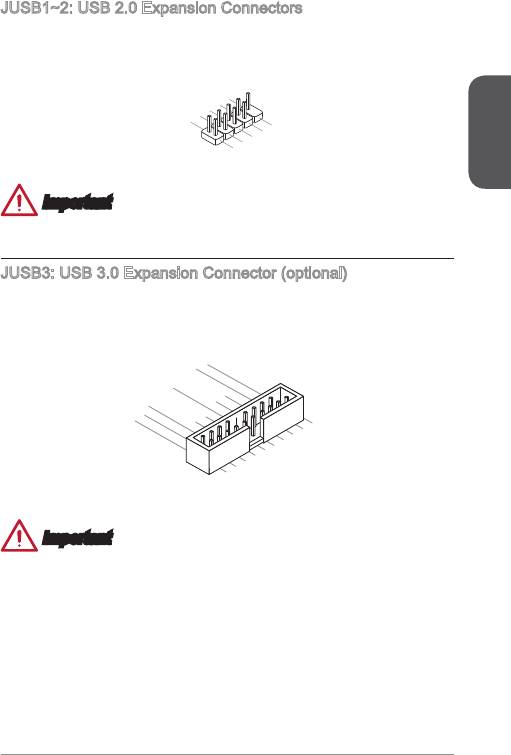
JUSB~2: USB 2.0 Expansion Connectors
This connector is designed for connecting high-speed USB peripherals such as USB
HDDs, digital cameras, MP3 players, printers, modems, and many others.
English
23
1
0
8
.
.
NC
6
G
.
r
4
U
o
.
S
u
2
U
S
B
n
.
V
1
d
C
B
+
1
C
-
9
.
7
N
.
G
o
5
3
.
U
r
P
o
i
.
S
u
n
1
U
S
B
n
.
V
d
B
0
C
C
0
+
-
Important
Note that the VCC and GND pins must be connected correctly to avoid possible
damage.
JUSB3: USB 3.0 Expansion Connector (optional)
The USB 3.0 port is backwards compatible with USB 2.0 devices. It supports data
transfer rates up to 5Gbits/s (SuperSpeed).
20.No
19.Power
18.USB3_RX_DN
17.USB3_RX_DP
Pi
16.Ground
n
15.USB3_TX_C_DN
14.USB3_TX_C_DP
13.Ground
12.USB2.0
11
. +
U
SB2.0
-
1.Power
2.USB3_RX_DN
3.USB3_RX_DP
4
.Ground
5.
6.USB3_TX_C_DP
U
7
SB3_TX_C_DN
8.
.Ground
9.
U
10.Ground
U
SB2.0
SB2.0
-
+
Important
•
Note that the VCC and GND pins must be connected correctly to avoid possible
damage.
•
To use a USB 3.0 device, you must connect the device to a USB 3.0 port through
an optional USB 3.0 compliant cable.
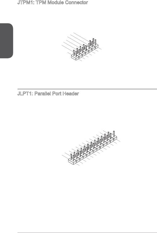
JTPM: TPM Module Connector
This connector connects to a TPM (Trusted Platform Module). Please refer to the
TPM security platform manual for more details and usages.
English
24
14.Ground
12.Ground
10.No
8.5V
6.Serial
Pi
4.3.3V
P
n
ower
2.3V
P
IR
Standby
ower
Q
p
ower
13.LP
11
9.LP
.LPC
C
7.LP
Fram
5.LP
C a
a
3.LP
C a
ddres
ddres
e
1.LP
C a
ddres
C
ddres
s &
C C
Rese
s &
s &
data
loc
data
t
s &
k
data
pin3
data
pin2
p
pin0
in1
JLPT: Parallel Port Header
This connector is used to connect an optional parallel port bracket. The parallel port
is a standard printer port that supports Enhanced Parallel Port (EPP) and Extended
Capabilities Parallel Port (ECP) mode.
2
6
2
.
4
N
2
.
o
2
G
2
.
r
P
0
G
o
i
1
.
r
u
n
8
G
o
n
1
.
r
u
d
6
G
o
n
1
.
r
u
o
d
4
G
n
1
.
r
u
d
2
G
o
n
1
.
r
u
d
0
G
o
n
8
.
G
r
u
d
.
o
n
6
L
r
u
d
.
P
o
n
4
P
T
u
d
n
.
I
E
N
_
d
2
2
S
.
R
I
5
T
L
2
.
A
R
#
I
3
S
F
#
N
2
.
L
D
#
1
P
C
#
1
.
B
E
T
9
1
.
U
7
A
1
.
P
C
S
5
1
.
R
K
Y
3
P
N
#
1
.
1
P
R
N
D
9
.
.
P
R
D
7
N
7
P
R
.
R
D
6
P
N
5
N
D
5
.
R
3
P
D
4
.
P
R
N
3
1
.
R
N
D
R
2
S
N
D
D
1
T
B
0
#
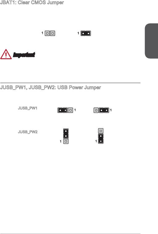
JBAT: Clear CMOS Jumper
There is CMOS RAM onboard that is external powered from a battery located on the
motherboard to save system conguration data. With the CMOS RAM, the system
can automatically boot into the operating system (OS) every time it is turned on. If
you want to clear the system conguration, set the jumpers to clear the CMOS RAM.
Keep Data Clear Data
English
Important
You can clear the CMOS RAM by shorting this jumper while the system is o.
Afterwards, open the jumper . Do not clear the CMOS RAM while the system is on
because it will damage the motherboard.
JUSB_PW, JUSB_PW2: USB Power Jumper
These jumpers are used to assign which USB and PS/2 ports could support “Wake
Up Event Setup” eld of BIOS.
JUSB_PW
(for onboard USB
connectors)
Support No Support (Default)
JUSB_PW2
(for back panel
USB ports & PS/2
ports)
Support No Support (Default)
25
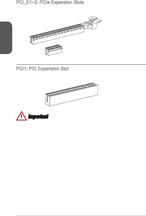
PCI_E~2: PCIe Expansion Slots
The PCIe slot supports the PCIe interface expansion card.
English
PCIe x6 Slot
PCIe x Slot
PCI: PCI Expansion Slot
The PCI slot supports the PCI interface expansion card..
PCI Slot
Important
When adding or removing expansion cards, always turn o the power supply and
unplug the power supply power cable from the power outlet. Read the expansion
card’s documentation to check for any necessary additional hardware or software
changes.
26
BIOS Setup
The default settings oer the optimal performance for system stability in normal
conditions. You may need to run the Setup program when:
■
An error message appears on the screen during the system booting up, and
requests you to run SETUP.
■
You want to change the default settings for customized features.
Important
English
•
Please load the default settings to restore the optimal system performance and
stability if the system becomes unstable after changing BIOS settings. Select the
"Restore Defaults" and press <Enter> in BIOS to load the default settings.
•
If you are unfamiliar with the BIOS settings, we recommend that you keep the
default settings to avoid possible system damage or failure booting due to
inappropriate BIOS conguration.
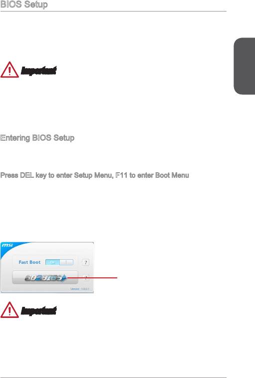
Entering BIOS Setup
Power on the computer and the system will start the Power On Self Test (POST)
process. When the message below appears on the screen, please <DEL> key to
enter BIOS:
Press DEL key to enter Setup Menu, F to enter Boot Menu
If the message disappears before you respond and you still need to enter BIOS,
restart the system by turning the computer OFF then back ON or pressing the
RESET button. You may also restart the system by simultaneously pressing <Ctrl>,
<Alt>, and <Delete> keys.
MSI additionally provides two methods to enter the BIOS setup. You can click the
“GO2BIOS” tab on “MSI Fast Boot” utility screen or press the physical “GO2BIOS"
button (optional) on the motherboard to enable the system going to BIOS setup
directly at next boot.
Click "GO2BIOS" tab on "MSI Fast
Boot" utility screen.
Important
Please be sure to install the “MSI Fast Boot” utility before using it to enter the BIOS
setup.
27
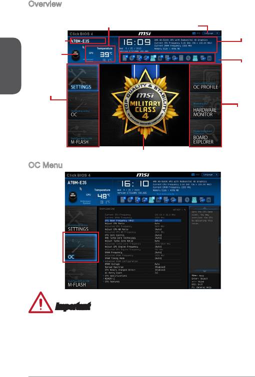
Overview
After entering BIOS, the following screen is displayed.
Temperature monitor
Language
System
information
Model name
English
Virtual OC
Genie Button
Boot device
priority bar
BIOS menu
selection
BIOS menu
selection
Menu display
OC Menu
Important
•
Overclocking your PC manually is only recommended for advanced users.
•
Overclocking is not guaranteed, and if done improperly, can void your warranty or
severely damage your hardware.
•
If you are unfamiliar with overclocking, we advise you to use OC Genie for easy
overclocking.
2
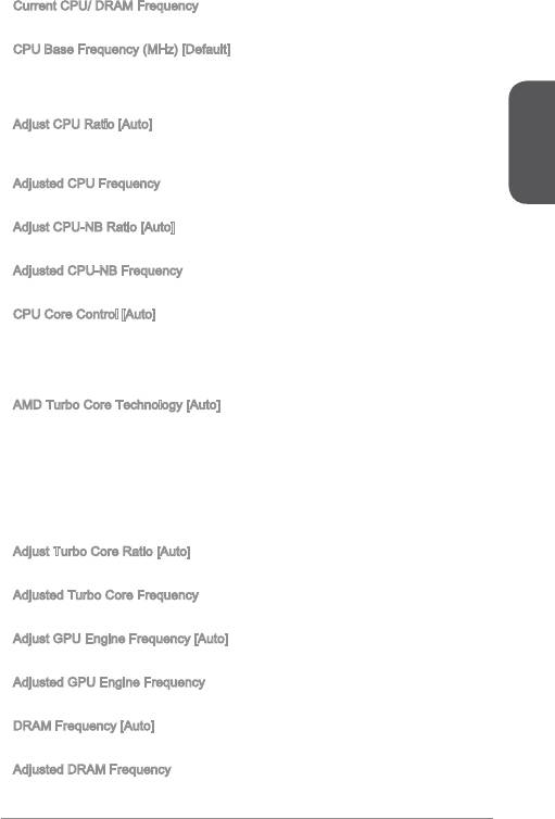
▶
Current CPU/ DRAM Frequency
These items show the current frequencies of installed CPU and Memory. Read-only.
▶
CPU Base Frequency (MHz) [Default]
Sets the CPU Base clock. You may overclock the CPU by adjusting this value.
Please note that overclocking behavior and stability is not guaranteed. This item
appears when the installed processor supports this function.
▶
Adjust CPU Ratio [Auto]
Sets the CPU ratio that is used to determine CPU clock speed. This item can only be
changed if the processor supports this function.
English
▶
Adjusted CPU Frequency
Shows the adjusted CPU frequency. Read-only.
▶
Adjust CPU-NB Ratio [Auto]
Sets the CPU-NB ratio that is used to determine CPU-NB clock speed.
▶
Adjusted CPU-NB Frequency
Shows the adjusted CPU frequency. Read-only.
▶
CPU Core Control [Auto]
Change the number of CPU Core in the system. If set to "Auto", the CPU will operate
under the default number of cores. [Options: Auto, One core per processor(Core 0
Only), One core per processor(Core 2 Only), One Compute Unit(Core 0 & ), One
Compute Unit(Core 2 & 3), One core per Compute Unit(Core 0 & 2)]
▶
AMD Turbo Core Technology [Auto]
Base on AMD Turbo Core Technology, part of CPU core ratio may pop down for
providing more performance headroom for active CPU core, even AMD Cool’n’Quiet
Technology is Disabled.
[Auto] Turbo Core Technology will linked to AMD Cool’n’Quiet
Technology.
[Enabled] Enables this function.
[Disabled] Disables this function.
▶
Adjust Turbo Core Ratio [Auto]
Species the Turbo Core frequency multiplier.
▶
Adjusted Turbo Core Frequency
Shows the adjusted Turbo Core frequency. Read-only.
▶
Adjust GPU Engine Frequency [Auto]
Adjust GPU Engine Frequency.
▶
Adjusted GPU Engine Frequency
Shows the adjusted GPU Engine frequency. Read-only.
▶
DRAM Frequency [Auto]
Sets the DRAM frequency. Please note the overclocking behavior is not guaranteed.
▶
Adjusted DRAM Frequency
Shows the adjusted DRAM frequency. Read-only.
29

▶
Intel Extreme Memory Prole (XMP) [Disabled]
XMP is the overclocking technology by memory module. This item will be available
when you install the memory modules that support XMP technology. When the XMP
is Enabled, the AMP will be forced to be disabled.
[Disabled] Disables this function.
[Prole ] Uses prole over-clocking settings of installed XMP memory
English
module.
[Prole 2] Uses prole2 over-clocking settings of installed XMP memory
module.
▶
AMD Memory Prole (AMP) [Disabled]
AMP is the overclocking technology by memory module. This item will be available
when you install the memory modules that support AMP technology. When AMP is
Enabled, the XMP will be forced to be disabled.
[Disabled] Disables this function.
[Prole ] Uses prole over-clocking settings of installed AMP memory
module.
[Prole 2] Uses prole2 over-clocking settings of installed AMP memory
module.
▶
DRAM Timing Mode [Auto]
Selects the memory timing mode.
[Auto] DRAM timings will be determined based on SPD (Serial Presence
Detect) of installed memory modules.
[Link] Allows user to congure the DRAM timing manually for all memory
channel.
[UnLink] Allows user to congure the DRAM timing manually for respective
memory channel.
▶
Advanced DRAM Conguration
Press <Enter> to enter the sub-menu. This sub-menu will be activated after setting
[Link] or [Unlink] in “DRAM Timing Mode”. User can set the memory timing for each
memory channel. The system may become unstable or unbootable after changing
memory timing. If it occurs, please clear the CMOS data and restore the default
settings. (Refer to the Clear CMOS jumper/ button section to clear the CMOS data,
and enter the BIOS to load the default settings.
▶
DRAM Voltage [Auto]
Sets DRAM voltage. If set to "Auto", BIOS will set DRAM voltage automatically or
you can set it manually.
▶
Spread Spectrum
This function reduces the EMI (Electromagnetic Interference) generated by
modulating clock generator pulses.
[Enabled] Enables the spread spectrum function to reduce the EMI
(Electromagnetic Interference) problem.
[Disabled] Enhances the overclocking ability of CPU Base clock.
30
Important
•
If you do not have any EMI problem, leave the setting at [Disabled] for optimal
system stability and performance. But if you are plagued by EMI, select the value
of Spread Spectrum for EMI reduction.
•
The greater the Spread Spectrum value is, the greater the EMI is reduced, and
the system will become less stable. For the most suitable Spread Spectrum value,
please consult your local EMI regulation.
•
Remember to disable Spread Spectrum if you are overclocking because even a
English
slight jitter can introduce a temporary boost in clock speed which may just cause
your overclocked processor to lock up.
▶
CPU Memory Changed Detect [Enabled]
Enables or disables the system to issue a warning message during boot when the
CPU or memory has been replaced.
[Enabled] The system will issue a warning message during boot and than
needs to load the default settings for new devices.
[Disabled] Disables this function and keeps the current BIOS settings.
▶
OC Retry Count
When overclocking has failed, setting this item as [,3] will allow system to reboot
/ 3 times with the same overclocked conguration. If overclocking has failed every
time, the system will restore the defaults.
▶
CPU Features
Press <Enter> to enter the sub-menu.
▶
AMD Cool’n’Quiet [Auto]
Enabled or disabled AMD Cool’n’Quiet function.
[Auto] Depends on AMD Design.
[Enable] Enables AMD Cool’n’Quiet function. The Cool’n’Quiet
technology can eectively and dynamically lower CPU speed
and power consumption.
[Disabled] Disables this function.
Important
When adjust CPU Ratio setting then Cool’n’Quiet function will be disabled
automatically. For CPU which supports the Turbo Core Tech., please set AMD Turbo
Core Technology and AMD Cool’n’Quiet as Disabled to retain the default CPU core
speed.
▶
SVM Mode [Enabled]
Enables or disables CPU Virtualization.
[Enabled] Enables CPU Virtualization and allows a platform to run
multiple operating systems in independent partitions. The
system can function as multiple systems virtually.
[Disabled] Disables this function.
3

▶
Core C6 State [Enabled]
Enables or disables C6 state support.
[Enabled] When the CPU enters C6 state, all cores will save
architectural state and reduce core voltages to zero volts.
Wake up the CPU from C6 state will take a lot longer.
[Disabled] Disables this function.
English
32


