Kastor Inferno Super Electrical sauna stoves: 4. ANVÄNDNING OCH SERVICE AV BASTUAGGREGAT
4. ANVÄNDNING OCH SERVICE AV BASTUAGGREGAT: Kastor Inferno Super Electrical sauna stoves
INFERNO
SUPER 8
4. ANVÄNDNING OCH SERVICE AV BASTUAGGREGAT
VARNINGAR:
Ett Kastor-aggregat är avsett att användas i familjebastu för att värma upp den till normal
badtemperatur. Inspektera basturummet innan du kopplar till aggregatet. Det får inte användas för andra ändamål.
Akta dig för ett varmt aggregat, stenarna och metalldelarna kan i badtemperatur vara brännande heta. Även i
övrigt skall man vara försiktig i närheten av aggregatet – speciellt med tanke på halkrisken. När man kastar bad
skall man se upp för stänkande heta vattendroppar samt het ånga. Föräldrarna skall övervaka små barn och se till
att anvisningarna följs. Det är förbjudet att vidröra rattarna på aggregatet omedelbart efter att man kastat bad (på
grund av den heta ångan). Man skall inte använda alltför mycket vatten på en gång eftersom den stora mängd
ånga som då frigörs kan förorsaka fara. Aggregatet får inte övertäckas och aldrig värmas upp utan stenar i
magasinet. Fri luftcirkulation speciellt bakom aggregatet skall garanteras. Man får aldrig hänga antändliga
föremål, t.ex. kläder eller mattor över eller för nära bastuaggregatet eftersom detta kan förorsaka brandrisk. Detta
aggregat tål inte havsvatten. I ett och samma basturum är det tillåtet att montera endast ett el-aggregat. Innan
aggregatet värms upp kontrollera att det är fäst på rätt sätt. Efter uppvärmningsperioden försäkra dig om att
tiduret har slagit av strömmen efter utsatt tid. Vid problem under garantitiden eller om Ni har något att fråga
kontakta tillverkaren före några som helst reparationer. Skydda händerna och använd handskar vid service och
reparationer.
Ta bort eventuella extra klistermärken och plastskydd innan aggregatet tas i bruk!
4.1. Bastustenarna
Aggregatet får aldrig värmas upp utan stenar. Vi rekommenderar traditionella brutna bastustenar (t.ex. peridotit
eller olivin). Lämplig storlek på stenar i elaggregat är 5–10 cm. Vill man ha fuktigt och långt bad kan en del
stenarna ersättas med stenar av täljsten som då läggs underst. Stenarna skall skuras med vatten innan magasinet
fylls. Stenarna skall kontrolleras minst två gånger om året. Stenmaterial på golvet under aggregatet är ett tecken
på förvittrade stenar.
4.2. Att fylla stenmagasinet
”Det innersta” av stenmagasinet bör fyllas med större stenar ända till toppen. Vid kanterna i övre delen kan man
placera litet mindre stenar. Man skall dock lägga märke till att stenarna inte när de kilas ihop eller faller ner inte
skadar rörelementen så att dessa inte förstörs i förtid. Stenarna kan nå högst en centimeter över aggregatets
mantel. Om de översta stenarna under badandet ofta förblir våta är stenmängden för stor eller så kan stenarna
vara för små.
4.3. Första uppvärmning
Första uppvärmningen görs med termostaten i maximiläge med full ventilation. Orenheter på rörelementen och
stenarna brinner då upp och kan osa en aning.
4.4. Uppvärmningsfasen
Uppvärmningsfasen är den tid som krävs för att bastun skall värmas upp till önskad badtemperatur. Tiden beror
bl.a. på önskad badtemperatur (termostatinställning), stenmängd, bastuvolym och ytmaterialen i bastun. Ju
mindre stenmassa, desto snabbare blir bastun varm, men med mindre stenmängd ger badkastandet inte lika bra
effekt. Uppvärmningsfasen är
normalt 40–70 minuter.
4.5. Användning
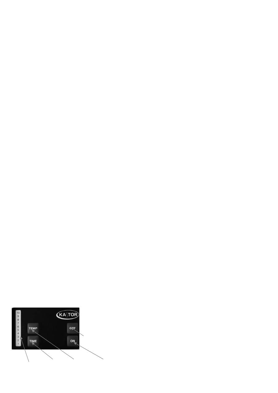
Aggregatet styrs med styrpanelen
Funktionerna
1
= visning,
2
= tidsinställning,
3
= temperaturreglage,
4
= påkoppling av ström,
5
= strömbrytare.
1 2 3 4

INFERNO
SUPER 9
4.5.1 Temperaturinställning (görs i läge ON)
Tryck TEMP – tidigare temperaturinställning visas i displayen. Siffrorna anger temperaturskalan i stigande
ordning. Pröva dig fram till lagom temperatur. Ställ först temperaturinställningen till 4. Efter detta kan du vid
behov höja eller sänka temperaturen tills du hittat den temperatur som passar dig själv bäst.
4.5.2. Manuell start/avstängning
Tryck ON för att slå på strömmen (signallampa tänds). Tryck OFF för att slå av strömmen (signallampa
slocknar). Minnesfunktionen väljer då automatiskt den temperatur som använts förra gången. Tryck TEMP för att
ändra på temperaturinställningen. Tiduret slår automatiskt av strömmen till aggregatet efter tre timmar. Vill du
slå av strömmen tidigare tryck OFF. Vill du fortsätta bada efter tre timmar tryck ON.
4.5.3. Inställning av tiduret (görs i läge OFF )
I detta fall visar siffrorna den förvalda tiden ( = efter hur många timmar som aggregatet slås på). Ställ in
förvalstiden enligt följande:
Tryck TIME – slå önskad förvalstid (1–10 timmar).
Tryck ON – Förvalstiden aktiveras och signallampan vid valt antal timmar börjar blinka. Då
uppvärmningsströmmen efter förvalstiden slås på värms aggregatet upp i tre timmar varefter strömmen
automatiskt slås av.
Du kan slå av uppvärmningen även tidigare genom att trycka OFF. Vill du fortsätta bada efter dessa tre timmar
tryck ON.
4.5.4. Huvudbrytare
Huvudbrytare finns under kopplingsdosan vid genomföringen av anslutningskabeln. Den används endast om
bastun inte kommer att användas under en längre tid. Styrpanelens minne töms vid strömavbrott.
4.5.3. Överhettningsskydd
Aggregatet är försett med inbyggt överhettningsskydd (THERM), som hindrar överhettning t.ex. om
temperaturreglaget inte fungerar. Återställning (kvittering) sker så att man trycker på nollställningsknappen t.ex.
med en lång skruvmejsel eller metallpinne. Före återställning måste orsaken till felet undersökas.
4.6. Service
Aggregatets elsystem får underhållas och repareras endast av auktoriserad montör. Vid byte av nya delar skall
man endast använda av tillverkaren godkända och definierade komponenter. Vid problem under garantitiden eller
frågor kontakta tillverkaren innan några som helst reparationsåtgärder vidtas. Stenarna kan man byta själv, likaså
rengöra bastuaggregatet utvändigt. Manteln rengörs med mild diskmedelslösning med hjälp av mjuka
rengöringsredskap varefter den torkas. För att skydda händerna använd handskar under service och rengöring.
4.7. Garanti
Denna produkt har tolv månaders garanti som gäller från köpdatum. Garantin gäller mot kvitto.
5. TILLVALSFUNKTIONER (kan tas i bruk endast av elmontör!)
5.1. Alternering med elvärme
Anslutningsstiften 5 och 6 i aggregatets kopplingsstycke är reserverade för styrning av elvärmen. Stift 6 ger en
styrspänning om 230 VAC alltid när uppvärmningsmotstånden är påkopplade. Alterneringssystemet möjliggör att
husets övriga uppvärmning kan vara påslagen medan tiduret är inställd till noll, förvalstid utnyttjas eller då
temperaturreglaget slår uppvärmningsmotstånden av.
5.2. Extern signallampa
Till anslutningsstiften 5 och 6 är det möjligt att koppla en signallampa. I så fall skall man komma ihåg att lampan
inte nödvändigtvis anger tidurets status utan anger huruvida uppvärmningsmotstånden är påslagna.
INFERNO
SUPER
10
1. INTRODUCTION
We thank you for your confidence in this KASTOR product. KASTOR heaters are known to be long lived and of
high quality. We recommend that you – and the person installing this heater – read these instructions carefully.
This manual should be always close at hand when needed. Once the installation is completed, this manual should
be handed to the sauna's owner or the person responsible for operating it. Before you do anything,
you should
read this manual and pay special attention to the “WARNINGS” part on page 12.
2. INSTALLATION
2.1. The Heater's Installation Location
The manufacturer's safe installation distances (
table 3
,
page 5
) must be adhered to. These distances are also given
on the heater's data plate. The attachment sizes for the wall mountings are shown in picture
1a
. The walls next to
the heater and the roof above it must not be protected with additional paneling, as the temperature in the wall
material may rise to dangerous levels. This heater is not designed to be embedded or installed in an alcove.
2.2. Attaching The Heater to The Wall
For easier installation the heater is equipped with a detachable wall mounting (
picture 1b
) that can be attached to
the wall beforehand (
picture 1a
). You may use the included attachment screws for installation in a wooden wall.
A thin panel board is not sturdy enough for the attachment. You should strengthen it from the backside using
board or plywood. Use heat resistant attachments (wedge or hammerset anchors, no plastic plugs) for masonry,
brickwork or other stone walls. The heater is lifted into its place according to
pictures 1c, 1d, 1e
. Do not lift the
heater by its coils or the upper plate of the back casing. Use the lower rim of the inner casing with support from
the upper part instead. A free corridor should be left at one side of the heater for maintenance work.
2.3. Connection to The Power Grid
The heater's electrical installation must be performed by a certified electrician. Check the heater's technical data
prior to connection. The connection to the power grid may only be performed by a professional electrician who is
certified according to present regulations. The heater is connected semi-permanently to a connection box on the
sauna wall. The connection cord should be a H07RN-F (VSN, VSB) rubber cable or equivalent. Do not use cords
with PVC insulation. The connection diagram is attached to this manual (picture 7) and to the heater's connection
box. Do not attach the heater's power feed to the error current connector
.
Remove the fuse, before detaching the
oven from the wall.
The connection is performed in the following manner before the heater is lifted into its place: 1. Remove the wall
mounting in the back of the heater, open the upper attachment screws at the sides and loosen the lower ones. 2.
Attach the throughput rubbers and cable grip. 3. Pass the cable through the throughput rubber to the connection
box. 4. Attach the cable to the cable grip and connector according to the connection diagram. 5. Provide
sufficient cable length to ensure that the cable does not run underneath the stone enclosure nor too close to the
heater's base plate. The heater's connector also provides for control of the electric heating (or the heater's signal
lamp). The package holds a second throughput rubber and cable grip with screws for this purpose. The control
cable's conducting material and diameter must be equal to the connection cable. The relay used in controlling the
electric heating gets a control voltage of 230 VAC from the heater. The conductors' diameters and numbers and
fuse values are given in the technical data table. The spray water tight connection box must not be attached more
than 50 cm above the ground.
2.4. Installation of The Sensor And Its Location on The Wall
The sensor is attached to the sauna wall on the heater's center line. If you wish to heat the sauna to higher
temperatures than usual, the sensor may be moved to the side according to
table 1 and picture 2
. Deviations
from the given measurements will cause fire hazards.
There are two alternatives for attaching the sensor to the wall. For surface attachment, the sensor's protective
cover is attached to the sauna wall (
picture 3A
). Attach the sensor to the cover and raise the cable grip strips at
the lower part of the cover. Bend the cable grip strips around the cable and bend the wings of the cover over the
sensor (
picture 3B
). For embedded installation, the sensor is attached directly to the wall (
picture 3C
).

INFERNO
SUPER
11
2.5. Changing The Location of The Control Panel (For Models DI-6D, DI-6K, DI-8K, DI-10K)
The heater control panel's location may only be switched by a professional with sufficient training. The control
panel has been factory installed to be used from the front of the heater. It may be turned to point to the side of the
heater in the following manner: 1) Release the attachment screw underneath the control panel. 2) Move the
rubber gaskets on the decorative piping further away from the control panel. 3) Remove the control panel by
pulling it outwards from the piping (the plastic material used tolerates bending well). 4) The keyboard connector
cable in the connection room has some slack to allow pulling the control panel further from the piping. 5) Detach
the cable at the keyboard's row connector. 6) Move the cable to the required side and pull it through. 7) Assemble
in reverse order.
2.6. Connecting A Separate CC Control Panel (For Models DI-6T, DI-8T, DI-10T)
There are no limits to the distance of the control panel from the sauna. The control cable from the CC control
panel is a 6 line low voltage cable that is connected to the circuit board on the heater according to the connection
diagram. The row connection numbering of the circuit board and the CC control panel are identical. Attach the
cable from the sensor to connectors 17 and 18 of the CC control panel.
3 SAUNA ROOM INSTRUCTIONS
3.1. The Sauna Room
The heat insulation of walls and ceiling must be sufficient, to avoid losing too much heat to the outside. Wood is
the most suitable surface material A wooden surface warms up quickly and radiates a pleasantly even heat to the
bather's skin. You should avoid masonry and other stone surfaces in the walls, as stone takes in too much heat
and would require a significantly more powerful heater than a wooden room of the same size. One square meter
of stone surface on the wall or ceiling above the heater's level is equal to 2-3 cubic meters of additional volume in
the room. A glass door and windows have similar effects on the sizing. Log walls require an additional 25% of
added power to the volume calculated in this manner.
Excessive height also adds unnecessary volume to the room. The distance between the highest bench and the
ceiling should not be too high, as the temperature decreases towards the floor.
A sufficient distance from bench to ceiling is about 110-120 cm. We recommend locating the heater as low as
possible (within safety limits). The sizes of sauna rooms are given in
table 2
.
3.2. Correct Air Circulation
Sufficient air exchange in the sauna is very important. A suitable amount for a family sauna would be about 6
times the sauna's volume per hour. Air removal happens either through gravity (= traditional, “natural
circulation”) or mechanically, through an air removal fan.
Mechanical air circulation (pictures 4 and 5):
Fresh air
is taken in (preferably from outside the house) through a 100 mm diameter pipe that is at least 500 mm
above the heater (
a
). The fresh air may also be piped in below the heater, close to the floor (
b
), as long as you
make sure that the cool air flow does not go straight along the floor to the exit air vent. The most important aspect
in air circulation is to ensure an efficient mixing of fresh air with heated air and the vapor from the thrown water.
The exit air vent should be preferably placed below the benches (
c
), as far from the air intake as possible.
The exit air
may also be fed through the washing room, e.g. underneath the door (e). The sauna should also have
a drying valve (f) behind the benches, near the ceiling. The drying valve is closed during the heating and bathing
phases and opened for the final drying out. The circulation fan is kept running throughout the bathing and
afterwards. It may be stopped for the preheating phase.
Gravity circulation – i.e. natural circulation (picture 6):
Fresh air
is taken in (preferably from outside the house) through a 100 mm diameter pipe, preferably from
underneath the heater or its immediate vicinity close to the floor
(b)
or, alternatively, above the heater
(a).
The
most important aspect in air circulation is to ensure an efficient mixing of fresh air with heated air and the vapor
from the thrown water.
The exit air
is fed out preferably from underneath the benches (
d
). Drying valve near the
ceiling (
f
). The exit air vent should be placed as far from the fresh air intake as possible. The exit air may also be
fed through the washing room, e.g. underneath the door (
e
). The exit air vent may be closed during preheating.
The exit air vent must be larger that the intake and be located higher up.
