DOCTER DOCTER®sight III: инструкция
Раздел: Оптика
Тип:
Инструкция к DOCTER DOCTER®sight III
analytik
jena
ROTPUNKT - REFLEXVISIER
RED - DOT REFLEX SIGHT
VISEUR REFLEX À POINT ROUGE
MIRA DE REFLEXIÒN DE PUNTO ROJO
Коллиматорный
прицел
DOCTER
®
sight III
Gebrauchsanleitung
Operating Instructions
Mode d’emploi / Instruction d’utilisation
Instrucciones para el uso
Инструкции
по
эксплуатации
Made in Germany
1 2 3 4 5 7

• • • • Achtung
Zur Montage der Visiereinrichtung muß die Waffe entladen und gesichert sein.
Vermeiden Sie den direkten Blick mit der Visiereinrichtung in Sonne,
Lichtbogen oder andere intensive Lichtquellen, um Augenschäden
auszuschließen. Zum Lieferumfang gehören Kleinteile, die nicht in
Kinderhände gehören.
• • • • Notice
Remove, where present, the magazine and all ammunition from your firearm.
Open the breech and ensure there is no round in the chamber. Point the
firearm in a safe direction and decock it. Engage, where possible, the safety.
Make sure to discharge the gun and put its safety catch on prior to mounting
the sight. Avoid looking directly into the sun, light arcs or other high-intensity
light sources to prevent eye damage. The equipment includes small
components. Keep away from children!
• • • • Attention
Avant le montage du viseur, il faut décharger l’arme et la mettre en sûreté.
Evitez la visée directe du soleil, d’un arc de lumière et de toutes autres sources
lumineuses intensives pour ne pas risquer un endommagement des yeux. La
livraison comprend de petites pièces qui n’appartiennent pas dans les mains
des enfants.
• • • • Atencion
Para montar la mira es absolutamente necesario que se haya descargado y
asegurado el arma. No dirija su mirada directamente hacia el sol, hacia arcos
de luz u otras fuentes luminosas intensas al usar el dispositivo para no
dañarse los ojos. El volumen de suministro incluye piezas pequeñas que
deben mantenerse fuera del alcance de los niños.
• • • • Внимание
Для
монтажа
прицела
оружие
следует
разрядить
и
поставить
на
предохранитель
.
Не
смотрите
через
прицел
на
солнце
,
электрическую
дугу
или
на
другие
яркие
источники
света
:
это
опасно
для
зрения
.
В
комплект
поставки
входят
детали
малого
размера
,
которые
следует
держать
в
недоступном
для
детей
месте
.

Allgemeine Informationen
Die
DOCTER
®
Reflexvisiere stellen hervorragende Zieloptiken modernster Bauart
dar. Sie bieten mit ihrer geringen Baugröße und Masse sowie der kompakten,
rohrlosen Bauform vielfältige Einsatzmöglichkeiten bei Jagd und Sport.
Die solide Verarbeitung, die hohe optische Leistung, ansprechendes Design und die
Funktionssicherheit auch bei extremen Witterungsbedingungen werden Ihnen Ihr
DOCTERsight III unentbehrlich machen.
Lieferumfang
Im Lieferumfang enthalten sind:
•
2 Senkschrauben M3x8 mit Innensechsrund (TORX) zur Befestigung auf der
Montageplatte
•
2 selbstklebende Dichtfolien
•
1 Stiftschlüssel T10 mit Innensechsrund (TORX) zum Anziehen der
Befestigungsschrauben
•
1 Schraubendreher 0,4x2,0
•
1 Skalenrad mit gerätespezifischer Skalenscheibe
•
1 Programmier- /Abdeckkappe
•
1 Knopfzelle 3 V, CR 2032
•
Gebrauchsanleitung
Technische Daten
Vergrößerung
1,07x
Sichtfenster
21 mm x 15 mm
Stellbereich Höhe
± 360 cm / 100 m
Stellbereich Seite
± 270 cm / 100 m
Stellwert je Skalenteil
3 cm / 100 m
Überdeckungsmaß bei Modell:
•
3,5 MOA
•
7,0 MOA
•
10 cm / 100 m
•
20 cm / 100 m
Parallaxefreie Beobachtungsentfernung
40 m
Stromversorgung
3 V, CR 2032 Lithiumknopfzelle
Abmessungen L x B x H
46,0 mm x 25,4 mm x 24,3 mm
Farbe Visierpunkt
Rot
Dichtigkeit
wasserdicht
Masse ohne Montage
25 g
Lassen Sie die Montage des DOCTERsight III und das Einschiessen der Waffe
durch einen Büchsenmacher vornehmen. Setzen Sie die Kappe erst nach der
Montage auf.
Inbetriebnahme
Zur Stromversorgung wird eine 3V – Lithiumbatterie CR 2032 benötigt. Jede andere
Art der Stromversorgung ist ausgeschlossen.
Setzen Sie die Batterie auf der Unterseite des Gehäuses so in das Batteriefach ein,
dass die Aufschrift der Batterie mit der Kennzeichnung des Plus-Pols zu erkennen
ist. Eine Gefahr zur Beschädigung der Elektronik durch ein verkehrtes Einlegen der
Knopfzelle besteht nicht. Die Batterie wird zur besseren Kontaktgabe von einem
Magnet an die vergoldete Kontaktplatte auf der Leiterplatine gezogen. Die
Kontaktfläche ist sauber zu halten (Reinigung mit Spiritus).
Batteriewechsel
Zum Batteriewechsel ist das DOCTERsight von der Montageplatte zu lösen. Das
Batteriefach befindet an der Geräteunterseite. Die verbrauchte Batterie wird durch
Ansetzen des Stiftschlüssels (oder Schraubendrehers) an der Auskerbung, die sich
rechts auf der Unterseite befindet, herausgenommen. Nach dem Batteriewechsel
wird das Visier wieder auf die Montageplatte gesetzt und mit den 2 Senkschrauben
befestigt. Ein erneutes Einschießen ist aufgrund der Präzisionsverstiftung nicht
erforderlich.
Ein- /Ausschalten
Ein mechanischer Ein- und Ausschalter ist nicht vorhanden. Um die Elektronik
abzuschalten wird die Programmierkappe aufgesetzt. Das Aufsetzen bewirkt ein
Abschalten der Elektronik.
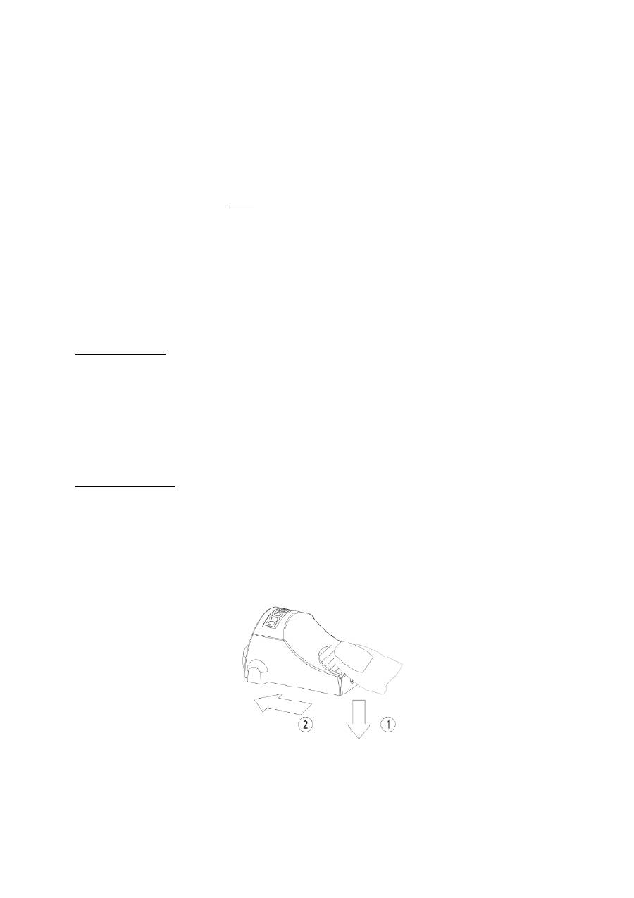
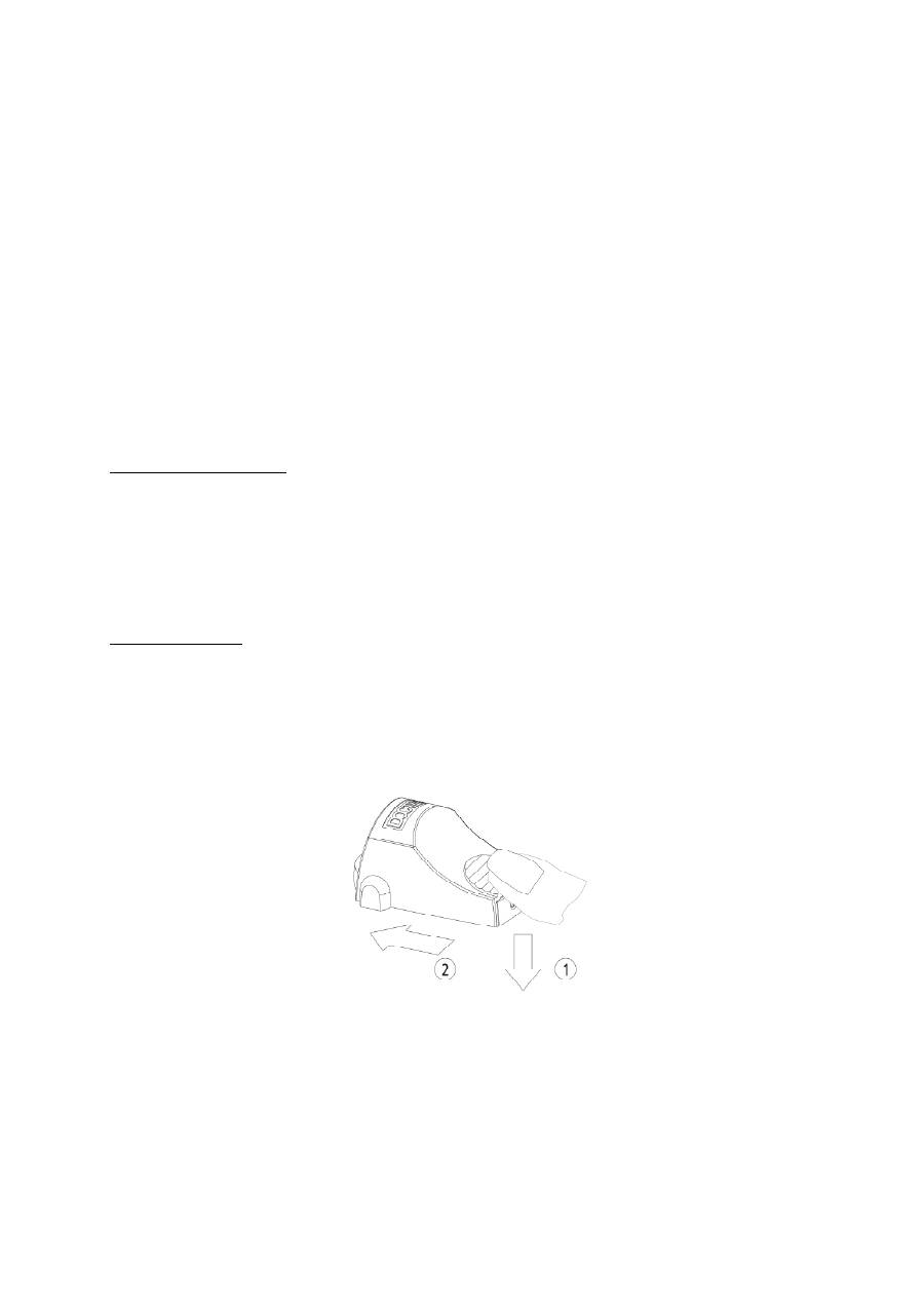
Beim Abnehmen der Programmierkappe legen Sie den Daumen auf die gerillte
Fläche der Kappe und drücken Sie dabei etwas nach unten. Schieben Sie die Kappe
nun nach vorne damit sich diese vom Gerät abhebt.

Montage
Das DOCTERsight lässt sich aufgrund einer Vielzahl verschiedener Adapterplatten
auf nahezu alle Waffentypen problemlos montieren. Zweckmäßigerweise wird Ihr
Büchsenmacher eine Montage entsprechend Ihren Bedürfnissen und dem Waffentyp
auswählen.
Unabhängig vom verwendeten Montagetyp verfügt die Adapterplatte oberseitig über
4 Präzisionsstifte. Die im Lieferumfang enthaltene Dichtfolie ist auf die Adapterplatte
aufzukleben. Ziehen Sie dafür die Klebefolie ab und kleben Sie die Dichtung
entsprechend den vorgestanzten Löchern auf die Adapterplatte. Das DOCTERsight
ist nur in Verbindung mit der Dichtfolie und der Adapterplatte wasserdicht.
Setzen Sie das DOCTERsight entsprechend der Befestigungsgewinde und der
Verstiftung auf die Montageplatte auf und befestigen Sie das Gerät mit den
beigefügten Senkschrauben.
Die Kombination aus Schraubenbefestigung und Stiftsicherung verhindert ein
Verschieben der Treffpunktlage während des Gebrauchs.
Einschießen
Das optische System des DOCTERsight III ist ab Werk auf eine Entfernung von 40 m
parallaxefrei justiert. Es ist eine Einschießentfernung zu wählen, die Ihren
Anforderung an das DOCTERsight III gerecht wird.
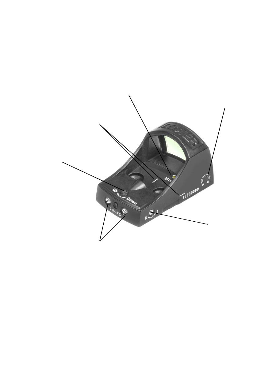
Das DOCTERsight III verfügt über eine getrennte Höhen- (1) und Seitenverstellung
(2). Diese sind oben und rechts am Gerät angeordnet und mit Drehrichtungspfeilen
markiert.
Die Einstellung nehmen Sie über die Schlitzschrauben mit beigefügtem Skalenrad
und Schraubendreher 0,4x2,0 vor.
Achtung: Vor jeder Verstellung Arretierungsschrauben (3) lösen.
Die Einstellungen für Höhe und Seite können unabhängig voneinander erfolgen. Der
vorhandene Stellbereich ermöglicht sowohl den Ausgleich von Ungenauigkeiten bei
der Montage als auch eine Ballistikkorrektur. Die Seitenverstellung hat in beiden
Richtungen Endanschläge.
Bei der Höhenverstellung ist zu beachten, das der Anschlag nach unten nur im
montierten Zustand vorhanden ist.
Beachten Sie, dass es zur Klemmung der Verstellungen kommt, wenn die jeweils
andere Stellrichtung auf Anschlag geschraubt worden ist.
Verstellung in Höhe und Seite
Um eine Beschädigung der Stellmechanik zu vermeiden, lösen Sie vor jeder
Verstellung in Höhe und Seite die Arretierung (3) des Stellmechanismus. Drehen Sie
dazu die zwei Klemmschrauben an der hinteren Seite des DOCTERsight eine viertel
Umdrehung vom Endanschlag zurück (entgegen dem Uhrzeigersinn). Verwenden Sie
dafür den beigefügten Schraubendreher 0,4x2,0. Die Verstellung muss sich
einwandfrei betätigen lassen.
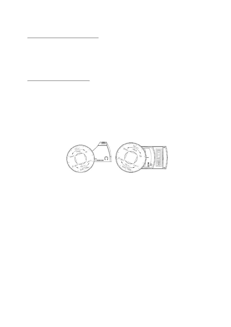
Einstellung der Treffpunktlage
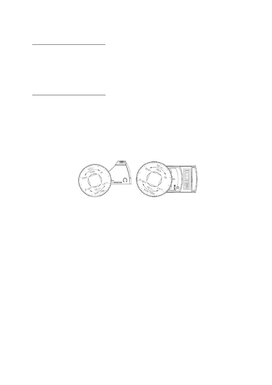
Zur Einstellung der Treffpunktlage ist eine Skalenscheibe im Lieferumfang enthalten.
Schieben Sie die Skalenscheibe mit der Skala zum Griff auf den mitgelieferten
Schraubendreher.
Setzen Sie nun den Schraubendreher auf die Höhen- (1) oder Seitenverstellung (2).
Entsprechend dem auf dem Gehäuse und dem Skalenrad angegeben Drehsinn,
erreichen Sie eine gerichtete Verstellung des Treffpunktes in Höhe oder Seite.
Zum Ablesen der Teilung verwenden Sie die Markierungen (4) neben den
Verstellungen oder eine markante Gehäusekante.
Stellen Sie nach der ersten Schußabgabe eine Abweichung von Zielpunkt (Absehen)
zu Treffpunkt fest, so ist diese wie folgt zu korrigieren:
•
Treffpunkt
unterhalb
des Zielpunktes (Waffe schießt tief):
Drehen der Verstellschraube in Richtung
Up
•
Treffpunkt
oberhalb
des Zielpunktes (Waffe schießt hoch
)
Drehen der Verstellschraube in Richtung
Down
•
Treffpunkt
links
des Zielpunktes (Waffe schießt links):
Drehen der Verstellschraube in Richtung
R / Right
•
Treffpunkt
rechts
des Zielpunktes (Waffe schießt rechts):
Drehen der Verstellschraube in Richtung
L / Left
Ein Skalenteil entspricht einer Verstellung von 3 cm auf 100 m bzw. 1 Winkelminute.
Bei anderen Einschießentfernungen ändert sich der Stellwert proportional zur
Entfernung, zum Beispiel:
1,5 cm auf 50 m oder 3 mm auf 10 m
Helligkeitssteuerung des Absehens
Eine integrierte Regelelektronik trägt den unterschiedlichen Beleuchtungsverhält-
nissen im praktischen Einsatz Rechnung. Die Leuchtpunktintensität wird automatisch
entsprechend der Umgebungshelligkeit in Zielrichtung angepasst. Die Messung ist
analog der Augenempfindlichkeit. Ein Abdecken des an der Vorderseite des Visiers
befindlichen Sensors führt zu einer sichtbaren Helligkeitsreduzierung des
Leuchtpunktes. Der Sensor darf deshalb nicht von Waffenteilen verdeckt werden.
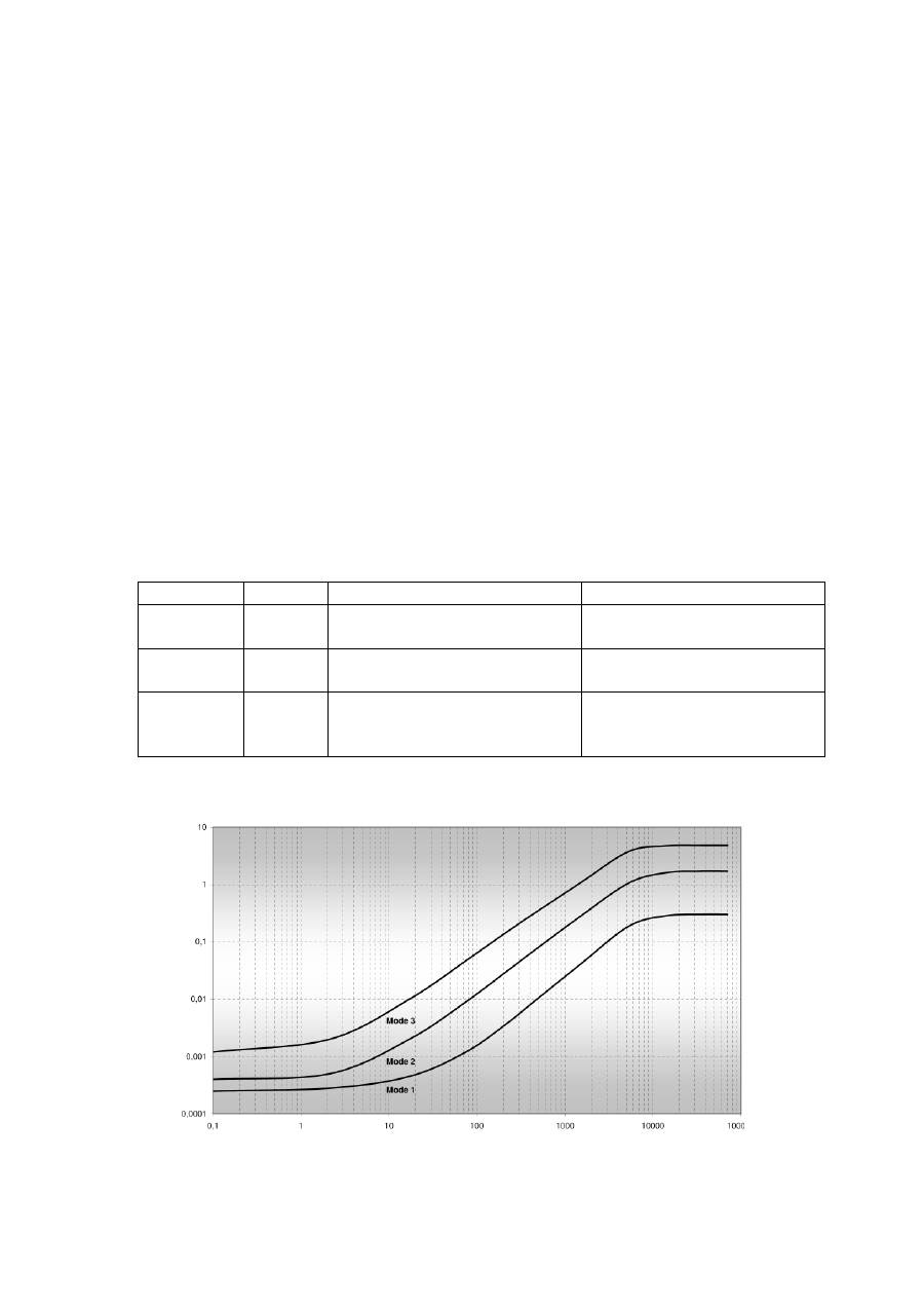
Neben der automatischen Regelung der Punkthelligkeit an die Lichtverhältnisse in
Zielrichtung kann eine individuelle Anpassung durch die Wahl aus 3 verschiedenen
Betriebsarten (Kennlinien) erfolgen. Die aktuell gewählte Betriebsart wird unmittelbar
nach der Abnahme der Programmierkappe über die zusätzliche MODE – LED (5) auf
der Oberseite des DOCTERsight angezeigt. Um störende Effekte durch diese
Anzeige zu vermeiden, ist die LED nur bei fast senkrechten Blick von oben auf das
DOCTER
sight III zu erkennen. Beachten Sie bitte auch, daß diese Anzeige ebenfalls
an die Umgebungshelligkeit angepasst wird, um einerseits eine gute Erkennbarkeit
am Tag zu erreichen und andererseits eine Blendwirkung in der Nacht zu verhindern.
Die Kennlinien sind bevorzugten Einsatzzwecken zugeordnet:
Blinkanzahl MODE
Merkmale
Bevorzugte Verwendung
1
M
inimal
Kennlinie mit niedrigstem
Energieverbrauch
Langzeit- und andere
Spezialanwendung
2
D
ynamik
Standardkurve mit
ausgewogenen Merkmalen
Universell
3
P
ower
Angehobene Grundhelligkeit
und
große maximale Helligkeit
Safari, bei Rotschwäche,
IPSC
Die Betriebsarten können in leicht vereinfachter Form so veranschaulicht werden:
Le
uc
ht
pu
nk
th
el
lig
ke
it
Umgebungshelligkeit in Lux
Ab Werk werden die Visiereinrichtungen mit MODE 2 (Dynamik) geliefert. Ein
Umschalten der Kennlinie ist unter Zuhilfenahme der Abdeckkappe, in der ein
Magnet integriert ist, möglich.
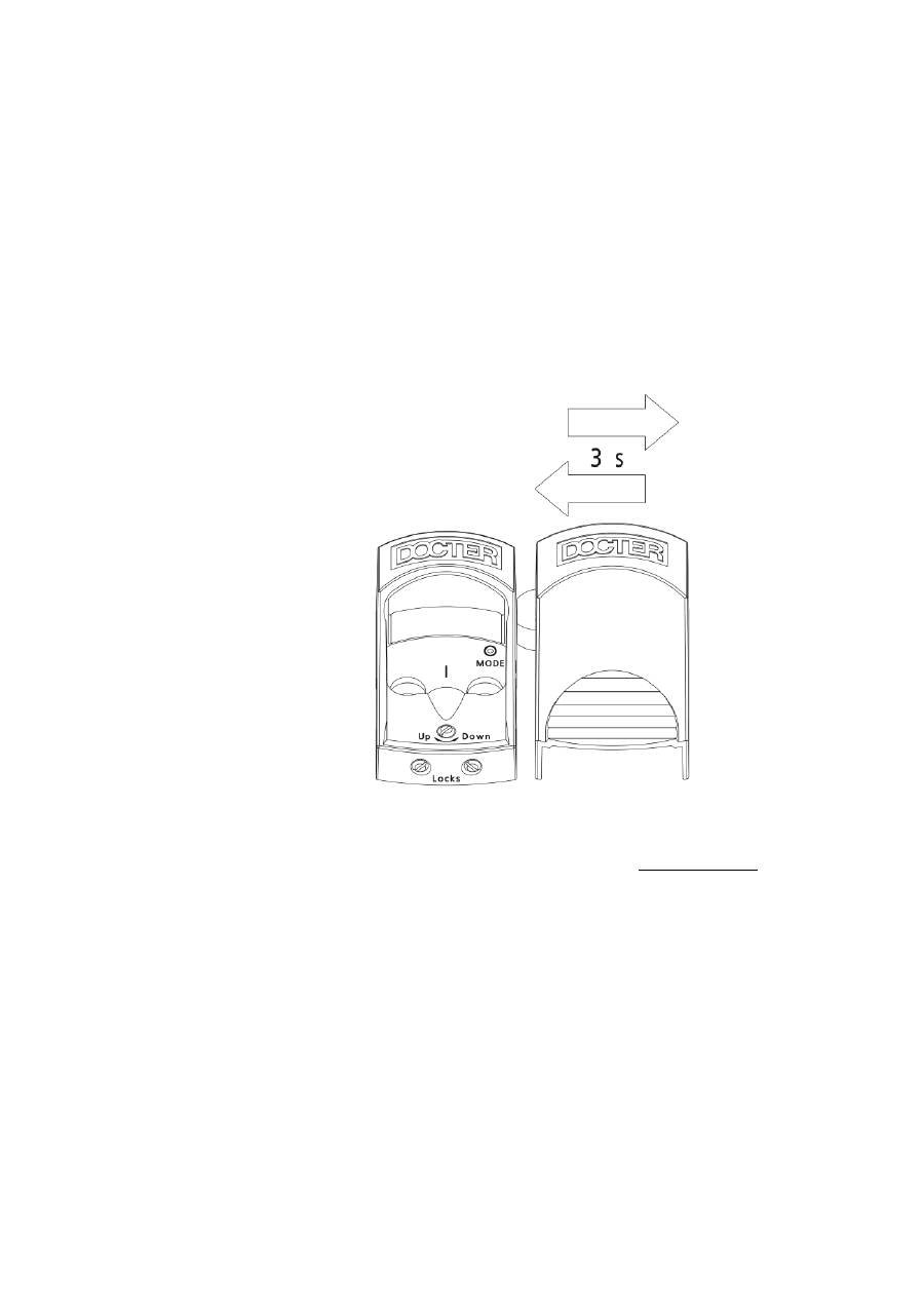
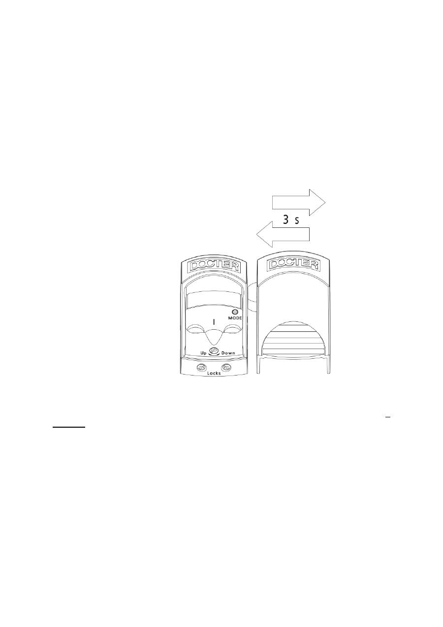
Änderung der Betriebsart (MODE)
Dazu ist die Kappe mit dem Magnetgeber (6) an der linken Seite zügig auf das
Hufeisenmagnetsymbol (7) an der rechten Geräteseite zu führen und nach 3
Sekunden wieder schnell zu entfernen.
Wenn das Signal erkannt wurde, erfolgt über die Mode-LED (5) einen Moment später
die Anzeige des neuen Zustandes. Diese Art der Umschaltung bietet einen hohen
Schutz gegen das unbeabsichtigte Umschalten durch die unkontrollierte Einwirkung
eines Magnetfeldes.
Es wird immer um einen Mode höher geschaltet und von 3 wieder in den Zustand 1.
Die eingestellte Betriebsart wird gespeichert und steht sofort nach dem Einschalten
zur Verfügung.

Batteriewarnung
Über die Mode – LED (5) wird signalisiert, wenn in nächster Zeit ein Batteriewechsel
vorgenommen werden sollte. Die Anzeige blinkt dann im Sekundentakt.
Bei erneutem Einschalten wird die Batteriespannung erneut überprüft. Wenn sich die
Batterie erholen konnte oder die Lichtverhältnisse anders sind, kann es sein, daß
zunächst keine erneute Warnung angezeigt wird. Trotz Batteriewarnung kann die
Visiereinrichtung noch längere Zeit (ca. 20% Reserve) betrieben werden. Die
Helligkeit des Leuchtpunktes geht jedoch zunehmend zurück und es kann eine
höhere Betriebsarteneinstellung als bisher vorgenommen, erforderlich sein.
Wartung und Pflege
Benutzen Sie Brillenputztücher zur Reinigung der Optik. Die Optikflächen sollten
vorher gegebenenfalls mit einem weichen, sauberen Tuch oder Haarpinsel vorsichtig
gesäubert werden – dabei keine chemischen Lösungsmittel verwenden.
Starke Verschmutzungen sollten mit destilliertem Wasser entfernt werden, weil es
sonst zu Kalkablagerungen auf den Oberflächen kommen kann.
Bei etwaigen funktionsbeeinträchtigenden Beschädigungen muß das Gerät an eine
autorisierte Servicewerkstatt eingesandt werden.
Hinweise
DOCTER Rotpunkt Reflexvisiere besitzen aufgrund ihrer Bauweise keinen
Dioptrienausgleich oder ähnliche, die Sehfehler des menschlichen Auges
ausgleichende Funktionsbaugruppen.
Alle individuellen Sehfehler des jeweiligen Schützen wirken sich somit direkt auf die
Kontur des wahrgenommenen Leuchtpunktes aus.
Scheinbare Unrundheit, sichelförmige Verzeichnung, „Sternenhaufen“ oder
„ausgefranste“ Kontur des Punktes deuten nicht auf ein defektes Gerät, sondern
vielmehr und ausschließlich auf eine physiologische Veränderung des Auges hin
(Astigmatismus).
Empfehlenswert ist dann die Verwendung einer korrigierenden Sehhilfe oder die
Überprüfung der Augen durch den Augenarzt.

Garantie
Wir bürgen für zwei Jahre Garantie in folgendem Umfang:
1. In der Garantiezeit werden Beanstandungen, die auf Material- und
Verarbeitungsfehler beruhen, kostenlos behoben. Wir behalten uns vor, dieses
durch Instandsetzung, Austausch fehlerhafter Teile oder Umtausch in ein
gleichartiges, einwandfreies Erzeugnis zu tun.
2. Bei Inanspruchnahme der Garantie ist das optische Gerät zusammen mit dem
Kaufnachweis – versehen mit Adresse und Unterschrift – sowie
Verkaufsdatum Ihres Händlers und der Darstellung der vorliegenden
Beanstandung der zuständigen DOCTER-Vertretung auf eigene Kosten zu
übersenden.
3. Ansprüche auf Garantieleistung bestehen nicht bei unsachgemäßer
Behandlung, Eingriffen und Reparaturen durch einen von unserer Firma nicht
autorisierten Servicedienst.
4. Von einer Garantie ausgenommen sind Verschleißerscheinungen,
Verschleißteile und sonstiges Zubehör. Dies gilt auch für diverse
Beschädigungen der Oberfläche des Erzeugnisses.
Für weitergehende mittelbare oder unmittelbare Schäden, gleich welcher Art und
Umfang, wird keine Haftung übernommen. Das Recht der Bundesrepublik
Deutschland hat Gültigkeit: Gerichtsstand ist Jena.

General Information
The DOCTER
®
reflex sights are excellent aiming optics devices of up-to-date design.
With their small size and low weight as well as their compact shape without using a
tube, they offer various possibilities of use on hunting and sport.
The solid workmanship, the high optical performance, an attractive design and the
functional reliability even in case of extreme weather conditions will cause your
DOCTERsightIII to become indispensable.
Delivery Extent
The delivery extent includes:
•
2 M3x8 countersunk socket screws (TORX) to fasten to the mounting plate
•
2 self-adhesive sealing foils
•
1 T10 hexagon wrench key (TORX) to tighten the fastening screws
•
1 screwdriver (0.4 x 2.0)
•
1 scale wheel with device-specific scale disc
•
1 programming/covering cap
•
1 coin cell (3 V, CR 2032)
•
Operating instructions
Technical Data
Magnification
1.07x
Sight window
21 mm x 15 mm
Elevation adjustment range
± 360 cm / 100 m
Windage adjustment range
± 270 cm / 100 m
Adjustment value per scale division
3 cm / 100 m
Overlap measure in case of model:
•
3.5 MOA.
•
7.0 MOA
•
10 cm / 100 m
•
20 cm / 100 m
Parallax-free sighting distance
40 m
Power supply
3 V, CR 2032 lithium coin cell
Dimensions (L x W x H)
46.0 mm x 25.4 mm x 24.3 mm
Color of target dot
Red
Tightness
Water-tight
Weight (without mounting accessories)
25 g
Let a gunsmith do the DOCTERsight III mounting and the shooting adjustment
of the gun. Put on the cap not before the mounting has been completed.
Putting into Operation
For the power supply, one CR 2032 lithium battery (3 V) is needed. Any other kind of
power supply is excluded.
Insert the battery into the battery compartment at the bottom of the enclosure such
that the labeling of the battery with the marking of the plus pole is visible. A danger to
damage the electronics due to an incorrect insertion does not exist. For a better
contact, a magnet causes the battery to be pulled toward the gold-plated contact
plate on the circuit board. The contact area is to be kept clean (cleaning using spirit).
Replacing the battery
To replace the battery, the DOCTERsight is to be removed from the mounting plate.
The battery compartment is located at the bottom of the device. The exhausted
battery is taken out by putting the wrench key (or the screwdriver) onto the notch
located at the right bottom side. When the battery has been replaced, the sight is put
back onto the mounting plate and is fastened with the 2 countersunk screws. Due to
the precision positioning pins, a new shooting adjustment is not required.
Switching on/off
A mechanical on/off switch is not present. To switch off the electronics, the
programming cap is put on. The putting-on effects a switching-off of the electronics.
When the programming cap shall be taken off, put the thumb onto the grooved area
of the cap and, at that, slightly press down. Now, push the cap forward such that it
lifts off from the device.

Mounting
Due to multitude of different adapter plates, the DOCTERsight can be mounted to
nearly all gun types without any problems. Your gunsmith will choose a convenient
mounting according to your requirement and to the gun type.
Independently of the used mounting type, the upper side of the adapter plate has 4
precision positioning pins. The sealing foil included in the delivery extend has to be
pasted onto the adapter plate. For that purpose, pull off the covering layer and paste
the seal onto the adapter plate where you have to consider the prepunched holes.
The DOCTERsight is water-tight only if the sealing foil has been applied properly.
Put the DOCTERsight onto the mounting plate where you have to consider the
fastening threads and the positioning pins. Then, fasten the device using the
delivered countersunk screws.
The combination of screw fastening and precision positioning pins prevents the hit
point position from shifting during the use.
Shooting Adjustment
Ex factory, the optical system of the DOCTERsight III is parallax-freely adjusted to a
distance of 40 m. You have to choose a shooting adjustment distance that meets
your requirements to the DOCTERsight III.
The DOCTERsight III has an elevation adjustment element (1) and a windage
adjustment element (2) that are separate from each other. These elements are
arranged at the top or at the right side of the device and are marked with rotation
direction arrows.
You will make the adjustment through of the slotted screws using the delivered scale
wheel and the delivered screwdriver (0.4 x 2.0).
Attention: Prior to each adjustment, the locking screws (3) have to be
loosened.
The elevation adjustment and the windage adjustment can be made independently of
each other. The available adjusting range allows the compensation of inaccuracies
on mounting as well as a ballistics correction. The windage adjustment has end stops
in both directions.
In case of the elevation adjustment, there has to be considered that the end stop in
downward direction is present in the mounted state only.
Please consider that the adjustments are clamped if there has been screwed up to
the end stop in the respective different adjusting direction.
Elevation and windage adjustment
To avoid the adjustment mechanism from being damaged, loosen the locking (3) of
the adjustment mechanism before doing any elevation and/or windage adjustment.
For that purpose, cause the two clamping screws at the rear of the DOCTERsight to
be moved back a quarter turn from the end stop (anticlockwise). To do that, use the
delivered screwdriver (0.4 x 2.0). The adjustment must be actuated without any
problems.
Adjusting the hit point position
To adjust the hit point position, a scale disc is included in the delivery extent. Push
the scale disc onto the delivered screwdriver where the scale has to be directed
toward the handle.
Now, cause the screwdriver to be set to the elevation adjustment (1) or to the
windage adjustment (2). According to the rotation sense shown on the enclosure and
on the scale wheel, you will get an aimed elevation or windage adjustment of the hit
point.
To read the division, use the markings (4) beside the adjustment elements or a
distinctive enclosure edge.
If you determine a deviation from the target point (light dot) to the hit point after the
first shoot, you can correct it as follows:
•
Hit point
below
the target point (gun shoots too deep):
Turn the adjustment screw in the
Up
direction.
•
Hit point
above
the target point (gun shoots too high
):
Turn the adjustment screw in the
Down
direction.
•
Hit point
to the left
of the target point (gun shoots too far left):
Turn the adjustment screw in the
R (Right)
direction.
•
Hit point
to the right
of the target point (gun shoots too far right):
Turn the adjustment screw in the
L (Left)
direction.
One scale division corresponds to a shift of 3 cm at 100 m or to 1 angular minute. In
case of other shooting adjustment distances, the adjustment value changes
proportionally to the distance. For example:
1,5 cm at 50 m or 3 mm at 10 m

Brightness Control of Light Dot
Using an integrated control electronics, the different lighting conditions in the practical
use are considered. The light dot intensity is automatically adapted according to the
environmental brightness in target direction. The measurement is analog to the
sensitivity of the human eye. When the sensor at the front side of the sight is
covered, a visible brightness reduction of the light dot occurs. Therefore, the sensor
must not be covered by gun parts.
In addition to the automatic dot brightness adaptation to the light conditions in target
direction, an individual adaptation can be made by means of choosing from three
different operating modes (characteristic curves). Immediately after taking off the
programming cap, the currently chosen operating mode is shown by means of the
additional MODE LED (5) at the top of the DOCTERsight. To avoid disturbing effects
due to this display, the LED is visible only when you nearly vertically look from above
onto the DOCTERsight III. Please consider that this display is also adapted to the
environmental brightness to have a good visibility on the day as well as to prevent a
dazzling effect in the night.
The characteristic curves are assigned to preferred application purposes:
Number of
flashes
MODE
Features
Preferred use
1
M
inimal
Curve with lowest energy
consumption
Long-term and other
special application
2
D
ynamic
Standard curve with balanced
features
Universal
3
P
ower
Increased basic brightness and
high maximum brightness
Safari, protanolamy,
IPSC
The operating modes can be demonstrated in a slightly simplified form as follows:
Li
gh
t
do
t
br
ig
ht
ne
ss
Environmental brightness (in lux)
Ex factory, the sight devices are delivered with MODE 2 (Dynamic). The
characteristic curve can be changed using the covering cap in which a magnet is
being integrated.
Changing the Operating Mode (MODE)
For that purpose, the magnet area (6) at the left side of the covering cap is to be
attached quickly to the horseshoe magnet symbol (7) at the device and, after 3
seconds, is to be taken off quickly.
When the signal has been detected, the mode LED (5) shows the new state a
moment later. This type of switching offers a high degree of protection against an
erroneous switching due to the uncontrolled effect of a magnetic field.
There is always switched upward by one mode and, from mode 3, back to the
mode 1. The set operating mode is saved and is immediately available after
switching-on.

Battery warning
The mode LED (5) signals if the battery should be replaced in the next time. Then,
the display flashes in intervals of one second.
When there is switched on again, the battery voltage is checked again. If the battery
could recover or the light conditions have changed, it can happen that a repeated
warning is not indicated for the time being. Despite the battery warning, the sight
device still can be operated for a longer time period (reserve of about 20 %).
However, the brightness of the light dot increasingly reduces and an operating mode
setting higher than that made before can be necessary.
Maintenance and Care
To clean the optics, use glasses cleaning clothes. Before doing that, the optics
surfaces should be carefully cleaned using a soft and clean cloth or a hair brush
where no chemical solvents are to be applied.
Heavy dirt should be removed using distillated water. Otherwise, furrings can occur
on the surfaces.
In case of possibly function-affecting damages, the device has to be sent to an
authorized service workshop.
Hints
Due to their specific construction, DOCTER red-dot reflex sights do not have a
diopter compensation unit or other function units that compensate for the visual
defect of the human eye.
Thus, all individual visual defects of the respective shooter have a direct effect on the
contour of the perceived light dot.
Seeming ovality, sickle-shaped distortion, "star clusters" or a "frayed" contour of the
dot do not mean a defective device, but rather and exclusively mean a physiological
change of the eye (astigmatism).
Then, it is recommended to use corrective glasses or to have the eyes checked by an
ophthalmologist.

Warranty
We grant a warranty of two years in the following extent:
1. In the warranty time, complaints that are based on material and processing
errors are cleared free of charge. We reserve the right to do such a clearance
by repair, by replacement of defective parts or by provision of a similar,
perfectly functioning product.
2. If the warranty is claimed, the optical device along with the proof of purchase
(with address and signature) as well as the date of selling by your dealer and a
description of the present complaint is to be sent to the responsible DOCTER
agency, at your own expense.
3. Claims for warranty performances do not exist in case of improper usage,
interventions and repairs by a service provider that is not authorized by our
company.
4. Wear and tear, wear parts and miscellaneous accessories are excluded from a
warranty. This also applies to diverse damages of the product surface.
We do not assume any liability for further-going direct or indirect damages,
irrespective of type and extent. It applies the law of the Federal Republic of Germany.
Place of jurisdiction is Jena.

Informations générales
Les viseurs reflex DOCTER
®
constituent d’excellents systèmes optiques de type
extrêmement pointu. Avec leurs dimensions et leur poids réduits et leur forme de
construction compacte et sans tube, ils offrent de nombreuses possibilités
d'utilisation pour la chasse et le sport.
Avec leur robustesse, leur performance optique élevée, leur design attrayant et leur
sécurité fonctionnelle, votre viseur DOCTERsight III vous deviendra indispensable
même dans des conditions météorologiques extrêmes.
Pièces fournies
Les pièces suivantes vous sont fournies :
•
2 vis à tête plate M3x8 à six pans internes (TORX) à fixer sur la plaque de
montage
•
2 films d’étanchéité autocollants
•
1 clé mâle coudéeT10 à six pans internes (TORX) pour serrer les vis de
fixation
•
1 tournevis 0,4x2,0
•
1 molette avec cadran spécifique à l'appareil
•
1 volet de programmation/recouvrement
•
1 pile bouton 3 V, CR 2032
•
Mode d’emploi
Fiche technique
Grossissement
x1,07
Témoin
21 mm x 15 mm
Plage de réglage en hauteur
± 360 cm / 100 m
Plage de réglage latéral
± 270 cm / 100 m
Valeur de réglage par graduation
3 cm / 100 m
Cote de recouvrement pour modèle :
•
3,5 MOA
•
7.0 MOA
•
10 cm / 100 m
•
20 cm / 100 m
Distance d’observation sans parallaxe
40 m
Alimentation électrique
Pile bouton lithium 3 V, CR 2032
Dimensions L x l x H
46,0 mm x 25,4 mm x 24,3 mm
Couleur point de visée
Rouge
Etanchéité
Etanche à l’eau
Poids non monté
25 g
