DOCTER DOCTER®unipoint 1-4x24: инструкция
Раздел: Оптика
Тип:
Инструкция к DOCTER DOCTER®unipoint 1-4x24
analytik
jena
ZIELFERNROHRE
RIFLESCOPES
LUNETTES DE VISEE
MIRAS TELESCOPICAS
ВИНТОВОЧНЫЙ
ОПТИЧЕСКИЙ
ПРИЦЕЛ
DOCTER
®
unipoint 1-4 x 24
DOCTER
®
unipoint 1,5-6 x 42
DOCTER
®
unipoint 2,5-10 x 50
DOCTER
®
unipoint 3-12 x 56
Gebrauchsanleitung
Operating Instructions
Mode d’emploi / Instructions d’utilisation
Instrucciones para el uso
Инструкции
по
эксплуатации
Made in Germany
5 1 4 3
2

•
•
•
•
Achtung
Aufgrund der starken Bündelung des Lichtes kann eine direkte Beobachtung der
Sonne mit einem Fernrohr zu Verletzungen der Augen führen und ist deshalb un-
bedingt zu vermeiden.
•
•
•
•
Notice
Due to the high and intense focussing of light a direct observation of the sun with
the telescope may cause eye injuries and must by all means be avoided!
•
•
•
•
Attention
En raison de la forte focalisation de la lumière, une observation directe du soleil
avec la lunette d’approche peut causer des blessures des yeux et doit donc être
impérativement évitée.
•
•
•
•
Atencion
Debido a la fuerte focalización de la luz, debe evitarse observar directamente el
sol con la mira telescópica, ya que los ojos podrían resultar dañados
.
•
•
•
•
Внимание
Из
-
за
сильного
и
интенсивного
фокусирования
света
,
строго
запрещается
смотреть
на
солнце
сквозь
оптический
прицел
,
так
как
это
может
привести
к
повреждению
глаз
!

Gebrauchsanleitung
Das von Ihnen erworbene
DOCTER
unipoint
ist ein Spitzenprodukt elektronischer
Hochtechnologie, optischer Fertigung und feinmechanischer Präzision. Die Komplexität
des Gerätes verlangt eine genaue Beachtung der Gebrauchsanleitung, um Fehlfunktio-
nen oder Beschädigungen zu vermeiden.
Das DOCTER
unipoint Leuchtabsehen für Tag und Nacht
stellt eine hervorragende Zieloptik der modernsten Bauart dar. Das Gerät bietet mit sei-
nem variablen Vergrößerungsbereich vielfältige Einsatzmöglichkeiten bei allen Jagdar-
ten unter den unterschiedlichsten Lichtverhältnissen am Tag wie auch in der Dämme-
rung.
Die solide Verarbeitung unter Verwendung modernster Technologien, die hohe optische
Leistung, das ansprechende, beständige Finish und die absolute Funktionssicherheit,
auch bei extremen Jagdbedingungen, werden Ihnen Ihr Zielfernrohr unentbehrlich ma-
chen.
Das
DOCTER
unipoint
beinhaltet folgende technische Konzeption:
Nicht mitvergrößerndes, zentriertes Absehen in der Okular-Bildebene
Gehäuse aus hochfestem Luftfahrtaluminium mit harteloxierter, korrosionsfester
Oberfläche
Mittelrohr mit 30mm Durchmesser und sehr langem Montagebereich
Hervorragende Variooptik mit großem Zoombereich, sowie Einsatz eines beson-
ders hochwertigen Objektivs
Okularschnellverstellung
Hochgenaue Absehenverstellung bei großem quadratischen Verstellbereich
Vergrößerungsschnellverstellung („Aktivwechsler“)
Lange Austrittspupillenschnittweite
Sehr gute Widerstandsfähigkeit gegen Umwelteinflüsse, absolute Staub- und
Wasserdichtheit, verbunden mit einer Stickstofffüllung
Einsatz hochwertiger Materialien wie Messing und nichtrostendem Edelstahl an
exponierten Teilen

Technische Daten
Modell
1
-4
x
2
4
1
,5
-6
x
4
2
2
,5
-1
0
x
5
0
3
-1
2
x
5
6
Vergrößerung
1x bis
4x
1,5x bis
6x
2,5x bis
10x
3x bis
12x
∅
Objektivöffnung [mm]
24
42
50
56
∅
Mittelrohr [mm]
30
∅
Objektivrohr [mm]
30
48
56
62
Gesamtlänge [mm]
279
323
345
376
Masse [g]
1)
490
560
640
680
∅
Austrittspupille [mm]
15
6,0
15
7,0
15
4,9
15
4,7
Sehfeld in m auf 100 Meter
31,0 bis
10,6
19,1 bis
7,0
11,3 bis
4,2
9,4 bis
3,5
Parallaxefreie Beobachtungs-
entfernung [m]
100
Augenpunkt [mm]
>90
Stellwert der Höhen-
und Seitenverstellung
[cm auf 100m]
2,0
1,0
1,0
1,0
Gesamtverstellbereich
in Höhe und Seite
[cm auf 100 m]
320
210
125
100
Augenfehlerausgleich
±
2,5
Funktionstemperaturbereich
-25
°
C bis +40
°
C
Lagertemperaturbereich
-40
°
C bis +55
°
C
Dichtigkeit
Wasserdicht 1 m
1) Mit Z-Schiene zusätzlich 20g schwerer

tipcontrol
– Absehenbeleuchtung mit digitaler Steuerung
Unsere Ingenieure, die stets um Weiterentwicklung bemüht sind, haben die Beleuch-
tungseinrichtung noch effizienter, komfortabler und vor allem sicherer gemacht.
Das von Ihnen erworbene Zielfernrohr verfügt über eine neuartige, stromsparende Mi-
krocontroller-Steuerung, die maximalen Bedienkomfort bei großem Dimmbereich mit
einer hohen Sicherheit vor ungewolltem Ein- oder Ausschalten verbindet. Bei Nichtge-
brauch erfolgt eine automatische Abschaltung. Unbeabsichtigtes Entladen der Batterie
kann so fast immer verhindert werden. Für das letzte Stück an Zuverlässigkeit wurde
außerdem noch ein Ersatzbatteriefach vorgesehen.
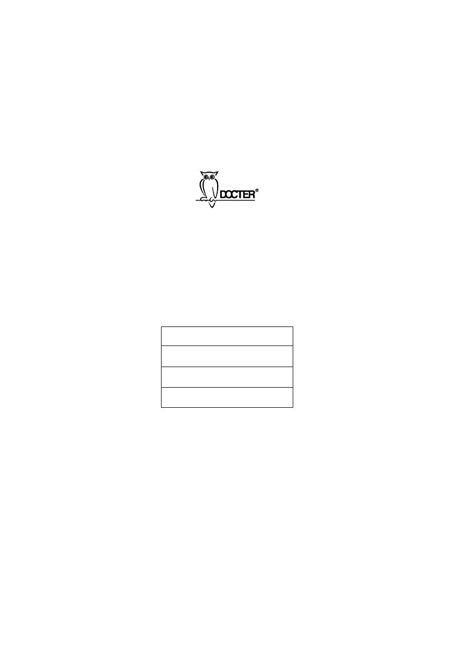
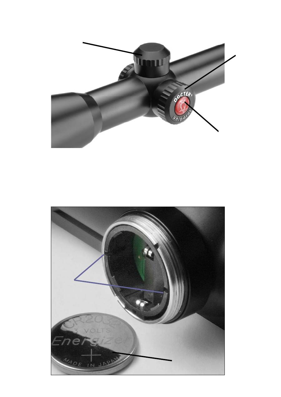
Einlegen der Batterie
Zuerst ist die Batteriefachkappe (1) abzuschrauben. Dann eine Lithium-Batterie
CR2032(2) (Lieferumfang) mit der Plus-Seite nach oben auf das Batteriefach legen und
in der Mitte eindrücken bzw. einklicken. Die Beschriftung der Knopfzelle muss lesbar
sein. Üben Sie bereits auch das korrekte Entnehmen der Batterie.
Entnehmen der Batterie
Zuerst muss die Batteriefachkappe (1) abgeschraubt werden. Nun kann die Knopfzelle
(2) entnommen werden, indem die Zelle mit Daumen oder Zeigefinger an einer der Stel-
len, wo der schwarze Rand geschlitzt ist (3), also in Richtung zum Objektiv oder zum
Okular,
kräftig
eingedrückt wird, bis die andere Seite der Batterie ausklinkt und über-
steht.
Bedienung
Sowohl Ein- und Ausschalten erfolgen durch
Doppelklick
auf die Taste mit dem
DOCTER-Logo (4), also zweimaliges unmittelbar aufeinanderfolgendes kurzes, kräftiges
Drücken.
Helligkeitseinstellung
Durch längeres Drücken der Steuerungstaste (4) von etwa
einer Sekunde wird die Helligkeitsänderung der Strichplattenbeleuchtung eingeleitet. Die
Helligkeit nimmt immer erst zu, solange die Taste gedrückt ist. Beim Loslassen bleibt die
aktuell eingestellte Helligkeit erhalten.
Anschließendes erneutes Drücken kehrt jeweils die Richtung der Helligkeitsänderung
um.
Beim Erreichen der maximalen oder minimalen Intensität blinkt das Absehen. Die Taste
(4) muß dann losgelassen werden, um wieder eine Richtungsänderung zu erzielen.
Dual-Memoryfunktion
Über die Memoryfunktion wird beim Wiedereinschalten eine sicher wahrnehmbare
Leuchtpunktintensität sofort eingestellt, die unter allen Beleuchtungsverhältnissen deut-
lich zu erkennen ist.
Durch einen
Dreifachklick
beim Einschalten wird die zuletzt eingestellte Helligkeit zu-
rückgerufen.
Automatische Abschaltung
Die Beleuchtungseinheit verfügt über eine zeitgesteuerte Abschaltung. Wenn 180 Minu-
ten keine Tastenbetätigung
erfolgt, wird die Beleuchtung abgeschaltet.

Reservebatteriefach
Die im Lieferumfang enthaltene zweite Lithium-Batterie CR2032 wird in einer Kappe (5)
der Stellgruppen-Abdeckung aufbewahrt. In diesem Batteriefach wird sie durch einen
kräftigen Magnet gehalten. Sie kann durch Aufschlagen des Fachs auf die flache Hand
gelöst werden.
Montage
Alle Modelle bestehen aus hochfestem Luftfahrtaluminium, die Rohrkörper werden mit
geringem Gewicht, hochgenau, als Monoblock gefertigt.
Ringvariante
Die Ausführung ohne Schiene eignet sich besonders für Aufschub-, Kipp- oder
Schwenkmontagen, bei denen das Rohr durch Klemmringe gehalten wird.
Innenschiene
Die beim Schienenmodell mittig angeordnete patentierte Montageschiene (6) (maß-
lich/baugleich der Zeiss-Innenschiene) lässt bei fachgerechter Montage des
DOCTER
unipoint keinen Wunsch an Funktionalität und Ausgewogenheit offen.
Vergrößerungswechsel
Je nach Schussentfernung und Lichtverhältnissen lässt sich die geeignete Vergrößerung
durch Drehen des inneren Okularrändelringes (Varioring) (7) mühelos einstellen.
Zur besseren Orientierung sind die wichtigsten Vergrößerungswerte auf dem Rändelring
(7) graviert, wobei auch jede beliebige Zwischenvergrößerung bei gleichbleibender Bild-
qualität, Sehschärfe und absolut unveränderter Treffpunktlage stufenlos einstellbar ist.
Der Varioring ist nichtlinear geteilt, wodurch eine bessere Anpassung an die Physiologie
des Auges erreicht wird.
Einstellung der Sehschärfe
Die Sehschärfe wird durch Drehen des äußeren Okularringes (8) eingestellt. Ein even-
tueller Augenfehler ist dann ausgeglichen, wenn bei entspanntem Sehen das Absehen
scharf wahrgenommen wird.
Es kann ein Augenfehlerausgleich von
±
2,5 Dioptrie vorgenommen werden.
Die Scharfeinstellung sollte prinzipiell bei der höchsten Vergrößerung vorgenommen
werden, da hierbei, bedingt durch die maximale Auflösung, die Sehschärfe am besten
beurteilt werden kann. Der spätere Wechsel der Vergrößerung ändert die vorgenomme-
ne Scharfeinstellung nicht.

Absehenverstellung
Das optische System des Zielfernrohrs ist ab Werk auf eine Entfernung von 100 m par-
allaxefrei justiert. Vom Büchsenmacher wird das Zielfernrohr montiert und im allgemei-
nen auf 100 m Entfernung eingeschossen. Durch die Absehenverstellung in Höhe und
Seite (Dome) ergibt sich die Möglichkeit, die Treffpunktlage entsprechend den jeweiligen
Schussbedingungen oder der verwendeten Munitionsart zu korrigieren.
Eine spezielle Ausführung des Umkehrsystems ermöglicht es, die Verschiebung der
Zielmarke im Fernrohrbild optisch auszugleichen, so dass das Absehen immer mittig im
Bild wahrgenommen wird. Die Zielmarke erscheint dadurch immer in der Mitte des Seh-
feldes, auch bei nachträglicher Korrektur der Treffpunktlage.
Die arrettierbaren Skalenscheiben (13) der Klickrastung zum Wiederauffinden des Null-
punktes ermöglichen eine exakte, reproduzierbare Treffpunktkorrektur.
Zur Einstellung des Absehens werden die beiden Schutzkappen von den Domen der
Absehenverstellung abgeschraubt. Durch Drehen der darunterliegenden Griffelemente
wird die Treffpunktlage verändert, und zwar am oberen Dom für die Höhe und am rech-
ten Dom für die Seite.
Höhenverstellung (H) (9)
Das Drehen der Griffelemente in Pfeilrichtung bewirkt eine Verschiebung des Treff-
punkts nach oben.
Seitenverstellung (R) (10)
Das Drehen der Griffelemente in Pfeilrichtung bewirkt eine Verschiebung des Treff-
punkts nach rechts.
Die definierten Rastschritte der Klickrastung sowie die Skalenscheiben (13) zum Wie-
derauffinden des Nullpunktes ermöglichen eine exakte, reproduzierbare Treffpunktkor-
rektur.
Das Ende des Verstellbereiches ist durch Anschläge spürbar. Es ist zu beachten, daß
das Absehen in der Bildmitte verbleibt und die Verstellung eine Verschiebung des Bild-
ausschnittes bewirkt (mittiges Absehen).
Die Absehenverstellung ist sehr robust und absolut wasserdicht. Um eine zufällige Ver-
stellung des Absehens zu vermeiden und Wasserdichtheit zu gewährleisten, sind die
Schutzkappen (11) stets wieder auf die beiden Dome aufzuschrauben. Dabei ist auf den
Sitz der Dichtringe (12) zu achten.
Achtung:
Um ein schnelles Auffinden der „eingeschossenen“ Nulllage des Absehens bei Verwen-
dung unterschiedlicher Munition oder Laborierungen zu gewährleisten, kann die Skalen-
scheibe (13) nach Lösen der Kreuzschlitzschraube (14) so gedreht werden, daß sich
beide Indexmarken (15) gegenüberstehen.
Der Verstellbereich für die Treffpunktkorrektur ist gut bemessen. Sollte die Skalenteilung
dennoch nicht ausreichen, empfehlen wir Ihnen die Montierung des Zielfernrohres vom
Büchsenmacher überprüfen zu lassen.

Zubehör
Zum Schutz der äußeren Optikteile werden miteinander verbundene Schutzkappen ge-
liefert.
Zum Schutz vor Seitenlicht kann auf Wunsch eine Teleskopgummilichtschutzblende ge-
liefert werden, die gleichzeitig den richtigen Augenabstand zum Okular gewährleistet
und einen etwaigen Rückstoß dämpft.
Pflege
Bei sorgsamer Behandlung ist die Lebensdauer des DOCTER
unipoint praktisch unbe-
grenzt.
Das Gerät sollte gegen größere Verschmutzung geschützt werden
Die Optikflächen sollten gegebenenfalls mit einem weichen, sauberen Tuch oder Haar-
pinsel vorsichtig gesäubert werden – dabei keine chemischen Lösungsmittel verwenden.
Starke Verschmutzungen sollten mit destilliertem Wasser entfernt werden, weil es sonst
zu Kalkablagerungen auf den Oberflächen kommen kann.
Es wird darauf hingewiesen, daß das Entfernen von Teilen des Zielfernrohres, zum Ver-
lust der Dichtigkeit und der Stickstofffüllung des Gerätes führen kann.
Bei etwaigen funktionsbeeinträchtigenden Beschädigungen muss das Gerät an eine
autorisierte Servicewerkstatt eingesandt werden.

Operating instructions
The
DOCTER
unipoint
you have purchased is a high-grade product of advanced
electronic optical production and fine mechanical precision. The complexity of the device
requires strict adherence to the operating instructions in order to prevent malfunction or
damage.
The DOCTER
unipoint light viewer for day and night
is an excellent target optical system of the most modern type. With its variable
enlargement range, the device offers many possibilities for use for all types of hunting
under the most varied light conditions in daylight as well as in twilight.
The solid construction using the most modern technologies, the high optical resolution,
the attractive finish and the absolute functionality also under extreme hunting conditions
will make your rifle scope indispensable.
The
DOCTER
unipoint
possesses the following technical features:
Non-enlarging centred viewing in the ocular picture level
Housing of high-grade aircraft aluminium with hard anodised corrosion-proof
surface
Centre tube with 30 mm diameter and very long support area
Excellent Variooptik with large zoom section, as well as use of a particularly high-
grade lens.
Quick-adjusting eye piece
Very accurate viewing adjustment with large quadratic adjustment range
Quick-acting enlargement setting (“Active adjuster”)
Long outlet pupil interface width
Very good resistance to environmental influences, absolutely dust- and water-
proof, together with a nitrogen filling
Use of high-grade materials such as brass and stainless steel for exposed parts

Technical data
Model
1
-4
x
2
4
1
.5
-6
x
4
2
2
,5
-1
0
x
5
0
3
-1
2
x
5
6
Enlargement
1x to
4x
1.5x to
6x
2.5x to
10x
3x to
12x
∅
Lens opening (mm)
24
42
50
56
Centre tube
∅
[mm]
30
Lens tube
∅
[mm]
30
48
56
62
Overall length [mm]
279
323
345
376
Mass [g]
1)
490
560
640
680
Ø Outlet pupil [mm]
15
6.0
15
7.0
15
4.9
15
4.7
Field of view at 100 metres
31.0 to
10.6
19.1 to
7.0
11.3 to
4.2
9.4 to
3.5
Parallax-free observation
distance [m]
100
Eye point [mm]
>90
Set value of the height and side
settings [cm per 100m]
2.0
1.0
1.0
1.0
Overall adjustment range
in height and side
[cm per 100 m]
320
210
125
100
Eye error equalization
±
2.5
Function temperature range
-25
°
C to +40
°
C
Storage temperature range
-40
°
C to +55
°
C
Watertightness
Watertight 1 m
With Z-rail additional 20g heavier

tipcontrol – view lighting with digital control
Our engineers, who are responsible for further developments have made the lighting
arrangement more efficient, comfortable and, above all, safer.
The rifle scope you have purchased possesses a new power-saving micro-controller that
combines the maximum of operating comfort at a large dimming range with a high
degree of safety against unintended on and off switching. When not in use, it switches
off automatically. Undesired use of the battery can thus almost always be avoided. And
for the final touch of reliability, a spare battery chamber is also provided.
Inserting the battery
First open the battery chamber cap (1). Then place a lithium battery
CR2032(2)(provided) into the battery chamber with the plus side facing upwards and
press it in the middle to click it into place. The writing on the button cell must be legible.
Also practice the correct removal of the battery.
Removing the battery
First screw the battery chamber cap (1) off. Now the button cell (2) can be removed in
that the cell is
strongly
pressed with the thumb or the forefinger at one of the points
where the black edge is slotted (3), thus in the direction of the lens or the ocular, until
the other side of the battery disengages and projects.
Operation
Both switching on and off occurs by means of a
double click
on the button with the
DOCTER logo (4), thus a strong quick short double- click.
Brightness setting
The change of brightness of the calibrating plate is carried out by means of a longer
press of approximately one second on the control button (4).
The brightness increases as long as the button is pressed. When released the
brightness adjustment remains.
Subsequent pressing reverses the direction of the change of brightness.
The view blinks when the maximum or minimum intensity has been reached. The button
(4) must then be released to achieve a reverse of the change again.
Dual-Memory function
On switching on again, a secure perceptible light point intensity that is adjusted with the
memory function is immediately set and can be recognised under all lighting conditions.
The last set brightness is recalled by means of a
three times click
when switching on.
Automatic switch off
The lighting unit possesses a time-controlled off switching. The lighting switches off if no
button operation has taken place for 180 minutes.

Reserve battery chamber
The second lithium battery R2032 included in the scope of delivery is kept in a cap (5) of
the adjusting group cover. It is retained in this battery chamber by a strong magnet.
When opening the cap it can be loosened by pushing it on to the flat of the hand.
Mounting
All models are made of high tensile aircraft aluminium, the tube body is manufactured
with low weight and high precision as a monoblock structure.
Ring variant
The model without rail is particularly suitable for push-on, tilting or swivelling installation.
Internal rail
With proper installation of the
DOCTER
unipoint
rail model, the centrally arranged
patented mounting rail (6) (dimensionally and structurally the same as the Zeiss internal
rail) leaves no wishes unsatisfied as regards functionality and balance
.
Change of enlargement
Depending on distance of shooting and the lighting conditions, the amount of
enlargement can easily be adjusted by turning the inner ocular knurl ring (Varioring) (7).
For better orientation, the most important enlargement values are engraved on the knurl
ring (7) whereby also any desired intermediate setting with the same picture quality,
sharpness and absolutely unchanged target point position can be steplessly set.
The Varioring in not divided linearly which achieves a better adaptation to the physiology
of the eye.
Setting the viewing sharpness
The viewing sharpness is adjusted by turning the outer ocular ring (8). A possible eye
error is compensated if, with relaxed seeing, the viewing sharpness is perceived.
An eye error compensation of
±
2.5 dioptres can be undertaken.
In principle, the sharpness setting should be carried out at the highest enlargement as
thereby the sharpness of viewing can best be evaluated at the maximum resolution. A
later change of enlargement does not change the sharpness setting.

Viewing adjustment
The optical system of the rifle scope is calibrated at the works for a distance of 100 m
parallax-free. The gun manufacturer mounts the rifle scope and it is shot-in generally at
100 m distance. With the viewing adjustment in height and side (Dome) there is the
possibility of correcting the target point position to the respective shooting conditions or
the type of ammunition used.
A special model of the reversing system permits the displacement of the target mark in
the scope picture to be optically equalized so that the viewing is always perceived to be
in the centre of the picture. The target mark thus always appears in the centre of the
field of view even with subsequent correction of the target point position.
The lockable scale plate (13) of the click stops for finding the zero point again permits an
exact reproducible target point correction.
In order to set the viewing, the two protective caps of the domes of the view adjustment
are unscrewed. The target point position is changed by rotating the grip elements lying
below it, the top dome for the height and the right dome for the side.
Height adjustment (H) (9)
The rotation of the grip element in the direction of the arrow results in the movement of
the target point upwards.
Side adjustment (R) (10)
The rotation of the grip element in the direction of the arrow results in the movement of
the target point to the right.
The defined calibrating stops of the click calibration as well as the scale plate (13) for
finding the zero point again permits an exact reproducible target point correction.
The end of the adjustment region is noticeable by the end stops. It must be noted that
the viewing remains in the picture middle and the adjustment results in a movement of
the picture section (central viewing).
The viewing adjustment is very robust and absolutely watertight. In order to avoid an
accidental displacement of the viewing and to ensure watertightness, the protective caps
(11) must always be screwed back on to the two domes. Here the seating of the sealing
rings (12) must be checked.
Caution:
In order to ensure quick finding of the “shot-in” zero position of the viewing when using
different ammunition or different powder compositions, the scale plate (13), after
loosening the Philips head screw (14), can be rotated so that the two index marks (15)
are opposite each other.
The setting range for the target point correction is well spaced. However, if the scale
division is insufficient, we recommend that the mounting of the rifle scope be checked by
a gun maker.

Accessories
Interconnected protective caps are supplied for protecting the external optical parts.
For protection from side light, a rubber light protection cover can be supplied if desired
that at the same time ensures the correct eye distance of the eye from the ocular and
damps out any recoil.
Maintenance
With careful handling, the life of the DOCTER
unipoint
is practically unlimited.
The device should be protected from much soiling.
The optical surfaces should occasionally be cleaned with a soft, clean cloth or fine brush
– do not use chemical solvents.
Strong dirt should be removed with distilled water otherwise lime deposits can form on
the surfaces.
Attention is drawn to the fact that the removal of parts of the rifle scope can lead to the
loss of watertightness and the loss of the nitrogen filling of the device.
In the case of any malfunctions or damage the device must be returned to an authorized
servicing workshop.

Mode d'emploi
L'appareil
DOCTER
unipoint
que vous venez d'acquérir est un produit sophistiqué à la
technologie électronique de pointe, à l'optique parfaite et d'une grande précision
mécanique. La complexité de l'appareil exige le respect exact des instructions
d'utilisation pour éviter les dysfonctionnements ou les dommages.
L'appareil DOCTER
unipoint avec éclairage de la visée pour le jour et la nuit
Une optique de visée parfaite de type moderne. Grâce au grossissement variable,
l'appareil offre de nombreuses possibilités d'utilisation pour tous les types de chasse et
les conditions de luminosité les plus variées, de jour comme dans la pénombre
La construction résistante qui utilise les technologies les plus modernes, la grande
puissance optique, la finition séduisante et solide et la sécurité de fonctionnement
absolue, même dans des conditions de chasse extrêmes, feront de vos lunettes de
visée un objet indispensable.
L'appareil
DOCTER
unipoint
comprend les aspects techniques suivants:
Visée non grossissante, centrée sur le plan focal de l'oculaire
Boîtier en aluminium pour l'aéronautique avec surface anodisé dur et résistante à
la corrosion
Tube central de 30mm de diamètre et très grande longueur d'assemblage
Zoom très important et utilisation d'un objectif de très grande qualité
Réglage rapide de l'oculaire
Réglage de visée de haute précision à grande zone de réglage quadratique
Réglage rapide du grossissement („changeur actif“)
Longue distance focale de la pupille de sortie
Très bonne résistance aux influences ambiantes, étanchéité absolue à la
poussière et à l'eau, remplissage d'azote
Utilisation de matières de grande qualité comme le laiton et l'acier spécial
inoxydable sur les éléments exposés

Caractéristiques techniques
Modèle
1
-4
x
2
4
1
,5
-6
x
4
2
2
,5
-1
0
x
5
0
3
-1
2
x
5
6
Grossissement
1x à
4x
1,5x à
6x
2,5x à
10x
3x à
12x
∅
ouverture de l'objectif [mm]
24
42
50
56
∅
tube central [mm]
30
∅
tube de l'objectif [mm]
30
48
56
62
Longueur totale [mm]
279
323
345
376
Poids [g]
1)
490
560
640
680
∅
Pupille de sortie [mm]
15
6,0
15
7,0
15
4,9
15
4,7
Champ visuel en m pour 100 m
31,0 à
10,6
19,1 à
7,0
11,3 à
4,2
9,4 à
3,5
Distance d'observation sans
parallaxe [m]
100
Point de vue [mm]
>90
Valeurs du réglage vertical et
latéral [cm pour 100m]
2,0
1,0
1,0
1,0
Plage totale du réglage vertical
et latéral [cm pour 100 m]
320
210
125
100
Correction des défauts de l'œil
±
2,5
Température de fonctionnement
-25
°
C à +40
°
C
Température de stockage
-40
°
C à +55
°
C
Etanchéité
Etanchéité à l'eau 1 m
1) Poids supplémentaire de 20g avec rail Z

tipcontrol
– Eclairage de la visée à commande digitale
Nos ingénieurs, qui se soucient de l'amélioration constante de nos produits, ont rendu le
dispositif d'éclairage encore plus efficace, plus confortable et plus sûr.
La lunette de visée que vous venez d'acquérir dispose d'une nouvelle commande à
microcontrôleur économisant l'énergie et offre un confort de commande maximal, une
large plage de variation de la lumière et une sécurité accrue contre l'allumage/l'arrêt
involontaire. L'arrêt est automatique en cas de non-utilisation. Cela permet presque
toujours d'éviter que la pile ne se décharge. Un compartiment de pile de rechange a en
outre été prévu pour un maximum de fiabilité.
Insérer la pile
Dévisser d'abord le capuchon du compartiment de la pile (1). Placer ensuite une pile au
lithium CR2032(2) (fournie) dans le compartiment avec le côté positif vers le haut, puis
appuyer au centre et encliqueter. L'inscription de la pile ronde doit être lisible. Exercez-
vous aussi déjà à la retirer correctement.
Retirer la pile
Le capuchon du compartiment de la pile (1) doit déjà être dévissé. On peut alors retirer
la pile ronde (2) en pressant
fortement
la pile avec le pouce ou l'index sur l'un des
points où le bord noir est fendu (3), donc en direction de l'objectif ou de l'oculaire,
jusqu'à ce que l'autre côté de la pile soit décliqueté et saille.
Commande
L'allumage et l'arrêt s'effectuent tous deux par un
double-clic
sur le bouton avec le logo
DOCTER (4), autrement dit en appuyant deux fois de suite de manière brève et forte.
Réglage de la luminosité
La modification de la luminosité de l'éclairage du réticule est amorcée en appuyant plus
longtemps, environ une seconde, sur le bouton de commande (4). La luminosité
augmente toujours tant que l'on appuie. La luminosité réglée est conservée lorsqu'on
relâche le bouton. Un nouvel appui a pour effet d'inverser le sens du réglage de la
luminosité. La visée clignote lorsque la luminosité maximale ou minimale est atteinte. Il
est alors nécessaire de relâcher le bouton (4) pour parvenir à une modification du sens
de réglage.
Fonction Dual-Memory
A la remise en marche, la fonction Memory règle immédiatement une intensité de point
lumineux perceptible et clairement identifiable dans toutes les conditions d'éclairage.
La luminosité réglée en dernier est rappelée par un
triple clic
à l'allumage.
Arrêt automatique
Le système d'éclairage est pourvu d'un arrêt synchronisé. L'éclairage s'arrête si aucun
bouton n'est actionné pendant 180 minutes.

Compartiment de pile de rechange
La seconde pile au lithium CR2032 fournie est conservée dans un capuchon (5) du
recouvrement du bloc de réglage. Elle y est maintenue au moyen d'un puissant aimant.
Elle peut être détachée dans la main à plat en donnant un coup sur le compartiment.
Montage
Tous les modèles sont en aluminium pour l'aéronautique hautement résistant, les tubes
sont de faible poids et fabriqués en un monobloc avec une grande précision.
Variante à anneaux
Le modèle sans rail convient particulièrement aux montages coulissant, basculant ou
oscillant à l'occasion desquels le tube est maintenu par des anneaux de serrage.
Rail intérieur
Le rail de montage (6) breveté placé au centre sur le modèle à rail (côtes/construction
identiques au rail intérieur Zeiss) répond à tous les souhaits en matière de fonctionnalité
et d'équilibre sous réserve du montage conforme de l'appareil DOCTER
unipoint.
Changement de grossissement
Le grossissement approprié peut être réglé sans problème en tournant l'anneau intérieur
moleté de l'oculaire (anneau Vario) (7) en fonction de la distance de tir et de la
luminosité.
Les principales valeurs de grossissement sont gravées sur l'anneau moleté (7) pour une
meilleure orientation, en l'occurrence de quoi il est possible d'ajuster en continu chaque
grossissement intermédiaire souhaité avec une qualité d'image et une netteté
constantes et une position de point d'impact absolument inchangée.
L'anneau Vario est divisé de manière non linéaire, ce qui permet d'obtenir une meilleure
adaptation à la physiologie de l'œil.
Réglage de la netteté
Le réglage de la netteté s'effectue en tournant l'anneau extérieur de l'oculaire (8). Un
éventuel défaut de l'œil est ensuite corrigé lorsque la visée est perçue avec netteté avec
vue détendue.
Il est possible d'effectuer une correction de
±
2,5 dioptries.
Le réglage de la netteté doit en principe être effectué avec grossissement maximal, car il
permet de pouvoir juger le mieux l'acuité visuelle en raison de la résolution maximale. Le
changement ultérieur de grossissement ne modifie pas le réglage de la netteté effectué.

Réglage de la visée
Le système optique des lunettes de visée est ajusté à l'usine à une distance de 100 m
sans parallaxe. Les lunettes de visée sont montées par l'armurier et généralement
réglées à une distance de 100 m. Le réglage vertical et latéral de la visée (dôme)
permet de corriger la position du point d'impact en fonction des différentes conditions de
tir et du type de munition utilisé.
La construction spéciale du système de renversement permet de compenser
optiquement le déplacement du repère de visée dans l'image de la lunette, de sorte que
la visée est toujours perçue au centre de l'image. Le repère de visée apparaît ainsi
toujours au centre du champ visuel, également en cas de correction ultérieure de la
position du point d'impact.
Les cadrans blocables (13) du dispositif à crans à déclic pour la recherche du point zéro
permettent d'obtenir une correction exacte et reproductible du point d'impact.
Pour effectuer le réglage de la visée, il est nécessaire de dévisser les deux capuchons
de protection des dômes du dispositif de réglage de la visée. La position du point
d'impact est modifiée en tournant les éléments de la poignée placés au-dessous,
précisément sur le dôme supérieur pour le réglage vertical et le dôme droit pour le
réglage latéral.
Réglage vertical (H) (9)
Le fait de tourner les éléments de la poignée dans le sens de la flèche a pour effet de
déplacer le point d'impact vers le haut.
Réglage latéral (R) (10)
Le fait de tourner les éléments de la poignée dans le sens de la flèche a pour effet de
déplacer le point d'impact vers la droite.
Les pas définis du dispositif à crans à déclic et les cadrans (13) pour la recherche du
point zéro permettent d'obtenir une correction exacte et reproductible du point d'impact.
La fin de la plage de réglage est perceptible grâce à des butées. Il convient de
considérer que la visée reste au centre de l'image et que le réglage a pour effet de
déplacer la coupe (visée centrale).
Le réglage de la visée est très robuste et absolument étanche à l'eau. Pour éviter un
réglage fortuit de la visée et garantir l'imperméabilité, les capuchons de protection (11)
doivent toujours être vissés sur les deux dômes. A cet effet, veiller au logement des
bagues d'étanchéité (12).
Attention!
Pour rechercher rapidement la position zéro „réglée“ de la visée avec l'emploi de
munitions différentes ou d'efforts, on peut tourner le cadran (13) après desserrage de la
vis à fentes en croix (14) de sorte que les deux repères d'index (15) soient face à face.
La plage de réglage destinée à la correction du point d'impact est bien mesurée. Si la
graduation de l'échelle ne suffit cependant pas, nous vous recommandons de faire
contrôler le montage de la lunette de visée par un armurier.

Accessoires
Des capuchons de protection reliés l'un à l'autre sont disponibles pour la protection des
éléments optiques extérieurs.
Pour la protection de l'éclairage latéral, nous pouvons vous fournir sur demande un
obturateur de protection télescopique en caoutchouc qui garantit en même temps la
distance exacte de l'œil par rapport à l'oculaire et amortit un éventuel recul.
Entretien
La durée de vie de l'appareil DOCTER
unipoint est pratiquement illimitée en cas de
traitement soigneux.
L'appareil doit être protégé du trop fort encrassement.
Les surfaces optiques doivent être, le cas échéant, soigneusement nettoyées avec un
chiffon doux et propre ou un pinceau fin. Ce faisant, ne pas utiliser de solvants
chimiques.
Eloigner les fortes salissures avec de l'eau distillée pour éviter les dépôts de calcaire qui
pourraient autrement se former sur les surfaces.
Nous attirons votre attention sur le fait que l'action de retirer des pièces de la lunette de
visée peut conduire à la perte de l'étanchéité et du remplissage d'azote de l'appareil.
En cas de dommages influençant sa fonction, l'appareil doit être envoyé à un atelier
SAV agréé.

Instrucciones para el uso
La mira telescópica
DOCTER
unipoint
que usted ha adquirido es un excepcional
producto de alta tecnología electrónica, fabricación óptica y precisión mecánica. La
complejidad del aparato hace necesario el cumplimiento exacto de las presentes
instrucciones para evitar funciones incorrectas y daños.
La retícula iluminada DOCTER
unipoint tanto para el día como para la noche
es un extraordinario sistema óptico de modernísima construcción. El aparato, con su
área de aumento variable, ofrece numerosas posibilidades de utilización en todos los
tipos de caza con las más diferentes condiciones de luz, tanto durante el día como al
amanecer y al atardecer.
Su compacta ejecución aplicando las tecnologías más modernas, su alto rendimiento
óptico, su atractivo diseño y su absoluta seguridad funcional incluso en condiciones de
caza extremas, harán que su mira telescópica le resulte indispensable.
La mira telescópica
DOCTER
unipoint
se basa en la siguiente concepción técnica:
Retícula centrada, sin aumento, en el plano focal del ocular
Carcasa de aluminio aeronáutico altamente resistente con superficie anodizada
dura, resistente a la corrosión
Tubo central de 30 mm de diámetro con una muy larga área de montaje
Excelente objetivo de foco variable con gran área de zoom, así como utilización
de un objetivo de especialmente alta calidad
Ajuste rápido del ocular
Ajuste de la retícula de alta precisión con una gran área de ajuste de forma
cuadrada
Ajuste rápido del aumento („cambiador activo“)
Larga distancia focal del anillo ocular
Muy buena capacidad de resistencia frente a influencias medio ambientales,
impermeabilidad absoluta a polvo y agua, en combinación con llenado de
nitrógeno
Utilización de materiales de muy alta calidad como latón y acero inoxidable en los
componentes expuestos

Datos técnicos
Modelo
1
-4
x
2
4
1
,5
-6
x
4
2
2
,5
-1
0
x
5
0
3
-1
2
x
5
6
Aumento
1x a
4x
1,5x a
6x
2,5x a
10x
3x a
12x
∅
de apertura del objetivo [mm]
24
42
50
56
∅
del tubo central [mm]
30
∅
del tubo del objetivo [mm]
30
48
56
62
Longitud total [mm]
279
323
345
376
Masa [g]
1)
490
560
640
680
∅
del anillo ocular [mm]
15
6,0
15
7,0
15
4,9
15
4,7
Campo visual a 100 m de
distancia en m
31,0 a
10,6
19,1 a
7,0
11,3 a
4,2
9,4 a
3,5
Distancia de observación sin
paralaje [m]
100
Punto ocular [mm]
>90
Valor del ajuste vertical y
horizontal [en cm a 100m]
2,0
1,0
1,0
1,0
Valor de ajuste completo en
vertical y horizontal [en cm a
100 m]
320
210
125
100
Compensación de defectos
visuales
±
2,5
Área de temperatura funcional
-25
°
C a +40
°
C
Área de temperatura en
almacén
-40
°
C a +55
°
C
Impermeabilidad
Impermeable al agua a 1 m
1) Con carril en Z tiene un peso adicional de 20g

tipcontrol
– Retícula iluminada con control digital
Nuestros ingenieros, afanados en todo momento en perfeccionar nuestros productos,
han conseguido que el dispositivo de iluminación sea todavía más eficiente, más
cómodo y, sobre todo, más seguro.
La mira telescópica que usted ha adquirido dispone de un novedoso mando
microcontrolador economizador de corriente, que combina el máximo confort en el
manejo teniendo un área grande de atenuación con una alta seguridad frente a un
encendido o apagado accidentales. Cuando no se utiliza, se produce una desconexión
automática, de forma que, en casi todos los casos, puede impedirse que la pila se
descargue. Para garantizar la máxima fiabilidad, se ha previsto adicionalmente un
compartimento para una pila de repuesto.
Colocación de la pila
En primer lugar, desatornille la tapa del compartimento de la pila (1). A continuación,
coloque una pila de litio CR2032 (2) (incluida en el ámbito de suministro) en el
compartimento con el lado más hacia arriba y presiónela y encájela por el centro. Debe
poder leerse la inscripción de la pila. Practique ya también cómo extraer la pila de forma
correcta.
Extracción de la pila
En primer lugar, desatornille la tapa del compartimento de la pila (1). Ahora ya puede
sacarse la pila (2) presionando
con fuerza
el botón con el dedo pulgar o el dedo índice
en uno de los puntos donde el margen negro esté ranurado (3), es decir, en dirección al
objetivo o al ocular. Hay que presionar hasta que el otro lado de la pila se suelte y
sobresalga.
Manejo
Tanto el encendido como el apagado tienen lugar haciendo
doble click
en el botón con
el logotipo DOCTER (4), apretándolo brevemente y con fuerza dos veces seguidas.
Ajuste de la claridad
Pulsando durante aproximadamente un segundo el botón de control (4) se modifica la
claridad de la iluminación de la placa reticulada. La claridad empieza a aumentar
mientras el botón esté pulsado, al soltarlo se mantiene la claridad ajustada.
Si a continuación se vuelve a pulsar, se invierte el sentido de cambio de la claridad.
Una vez alcanzada la intensidad máxima o mínima, la retícula se ilumina de forma
intermitente. El botón (4) debe soltarse para que el sentido se vuelva a invertir.
Función de memoria dual
Con la función de memoria, al volver a encender el aparato, se ajusta de forma
inmediata una intensidad del punto luminoso que puede percibirse de forma segura y
puede reconocerse claramente en todas las condiciones de iluminación.
Haciendo
tres veces click
al encender el aparato, se vuelve a ajustar la claridad que se
había ajustado por última vez.
Desconexión automática
La unidad de iluminación lleva una desconexión controlada por tiempo. Si durante 180
minutos no se ha accionado ningún botón, la iluminación se desconecta.

Compartimento de la pila de reserva
La segunda pila de litio CR2032, incluida en el ámbito de suministro, se encuentra en
una tapa (5) de la cubierta del grupo de ajuste. En este compartimento, la pila se
mantiene fijada gracias a un potente imán. Abriendo y golpeando suavemente el
compartimento, puede desprenderse y recogerse en la palma de la mano.
Montaje
Todos los modelos son de aluminio aeronáutico altamente resistente, los tubos se
fabrican de forma ultraexacta como monobloque y con un bajo peso.
Variante con anillo
El modelo sin carril es especialmente apto para el montaje por enchufe, inclinación o
giro, siendo sujetado el telescopio por medio de anillos.
Carril interior
En el modelo de carril, el carril de montaje (6) patentado (es en cuanto a dimensión y
construcción igual al carril interno de Zeiss) está situado en la parte central y satisface
absolutamente cualquier deseo en cuanto a funcionalidad y equilibrio si el
DOCTER
unipoint está montado correctamente.
Cambio de aumento
Dependiendo de la distancia de tiro y de la luz existente, el aumento puede ajustarse
fácilmente girando el anillo moleteado ocular interior (anillo variable) (7).
Para facilitar la orientación, en el anillo (7) aparecen gravados los valores de aumento
más importantes, pudiendo ajustarse igualmente cualquier aumento intermedio con la
misma calidad de imagen, agudeza visual y sin variar la posición del punto de imparto.
El anillo tiene una división no lineal, alcanzando así una mejor adaptación a la fisiología
del ojo.
Ajuste de la agudeza visual
La agudeza visual se ajusta girando el anillo ocular exterior (8). Un posible defecto
visual queda compensado cuando, al mirar de forma relajada, se percibe la retícula de
forma nítida.
Puede alcanzarse una compensación de defectos visuales de
±
2,5 dioptrías.
El ajuste de la agudeza debería realizarse, en principio, con el máximo aumento dado
que, debido a la máxima resolución, es como mejor puede valorarse la agudeza visual.
Si, posteriormente, se modifica el aumento, el ajuste de la agudeza no se ve
influenciado.

Ajuste de la retícula
El sistema óptico de la mira telescópica viene ajustado de fábrica sin paralaje a una
distancia de 100 metros. El armero, al montar la mira en el arma, suele ajustarla a esta
misma distancia. Además, la posibilidad del doble ajuste de la retícula en altura y
horizontalmente (domos) permite corregir la posición del punto de impacto según las
condiciones concretas de disparo o el tipo de munición utilizado.
La especial ejecución del sistema de inversión incorporado permite compensar
ópticamente el desplazamiento del punto de mira en la imagen de forma que la retícula
siempre se percibe en el centro de la imagen. De esta forma, el punto de mira se
encuentra siempre en el centro del campo visual, también si se ha corregido la posición
del punto de impacto.
Los cuadrantes enclavables (13) del ajuste de click para volver a encontrar el punto
cero, facilitan una corrección del punto de impacto exactamente reproducible.
Para el ajuste de la retícula se destornillan las dos caperuzas protectoras de los domos
de ajuste. Haciendo girar los discos inferiores se modifica la posición del punto de
impacto: en el domo superior se modifica la altura y en el domo derecho la posición
horizontal.
Ajuste vertical (H) (9)
Girando el disco en dirección de la flecha, se consigue desplazar la posición del punto
de impacto hacia arriba.
Ajuste horizontal (R) (10)
Girando el disco en dirección de la flecha, se consigue desplazar la posición del punto
de impacto hacia la derecha.
Los pasos definidos de enclavamiento del ajuste de click, así como los cuadrantes (13)
para volver a encontrar el punto cero, facilitan una corrección del punto de impacto
exactamente reproducible.
El final del área de ajuste se hace notar por topes. Debe tenerse en cuenta que la
retícula permanece en el centro de la imagen y que los ajustes provocan un
desplazamiento del sector de imagen (retículo centrado).
El ajuste de la retícula es de gran robustez y absolutamente impermeable al agua. Al
objeto de evitar un desajuste accidental de la retícula y de asegurar la debida
impermeabilidad al agua, hay que atornillar siempre de nuevo las caperuzas protectoras
(11) a ambos domos, prestando atención a que los anillos de junta (12) tengan un
asiento exacto.
Atención:
Para asegurar una rápida localización del punto de ajuste de la retícula tras la utilización
de distintos tipos de munición o recargas, el cuadrante (13) puede girarse tras soltar el
tornillo (14), de forma que las dos marcas de índice (15) coincidan.
El área de ajuste para la corrección del punto de impacto es suficientemente grande
para las necesidades prácticas, pero, si alguna vez la escala resulta insuficiente,
recomendamos solicitar a su armero que compruebe el montaje de su mira telescópica.

Accesorios
Con el fin de proteger las superficies ópticas exteriores, se suministran caperuzas
protectoras unidas entre sí.
Para proteger contra la luz lateral, podemos suministrar también, a petición, un
diafragma protector de caucho que garantiza la distancia correcta del ojo al ocular y, a
la vez, amortigua los posibles retrocesos del arma.
Cuidado
La vida útil de la DOCTER
unipoint es prácticamente ilimitada, si se le cuida
debidamente.
El aparato debe protegerse de suciedad mayor.
En caso necesario, las superficies ópticas deben limpiarse con cuidado con un paño
suave y limpio o con un pincel. No utilizar disolventes químicos.
En caso de suciedad mayor, esta deberá eliminarse con agua destilada, porque, de otro
modo, puede depositarse cal en las superficies.
Hay que indicar que, al retirar componentes de la mira, puede producirse la pérdida de
impermeabilidad y del llenado de hidrógeno del aparato.
En caso de daños que afecten a sus elementos funcionales, el aparato deberá enviarse
a un taller de servicio autorizado para su reparación.

Инструкция
по
эксплуатации
Приобретенный
Вами
DOCTER
unipoint
представляет
собой
точномеханический
продукт
высшего
качества
,
результат
разработки
электронных
высоких
технологий
и
оптического
производства
.
Ввиду
сложности
прибора
,
необходимо
внимательно
ознакомиться
с
инструкцией
по
эксплуатации
с
тем
,
чтобы
избежать
неисправностей
и
повреждений
.
DOCTER
unipoint –
прекрасный
обзор
в
режиме
дня
и
ночи
DOCTER
unipoint
представляет
собой
выдающееся
оптическое
прицельное
устройство
самой
современной
конструкции
.
Благодаря
изменяющему
диапазону
увеличения
прибор
предлагает
многочисленные
возможности
его
использования
во
время
охоты
любого
вида
,
в
различных
световых
условиях
,
как
днем
,
так
и
в
сумерки
.
Солидная
обработка
,
ставшая
возможной
благодаря
использованию
современных
технологий
,
высокая
оптическая
мощность
,
приятная
и
прочная
отделка
,
а
также
абсолютная
надежность
функционирования
даже
в
экстремальных
условиях
охоты
сделают
Ваш
оптический
прицел
незаменимым
для
Вас
.
DOCTER
unipoint
придерживается
следующей
технической
концепции
:
Неувеличивающийся
,
центрированный
обзор
в
окулярной
плоскости
изображения
Корпус
из
высокопрочного
авиационного
алюминия
с
анодированной
,
коррозионностойкой
поверхностью
Средняя
трубка
диаметром
в
30
мм
с
очень
большим
диапазоном
монтажа
Выдающаяся
оптическая
система
с
переменным
фокусным
расстоянием
,
с
большим
диапазоном
объектива
,
а
также
использованием
высококачественного
объектива
Быстрое
регулирование
окулярной
трубки
Высокоточное
регулирование
обзора
при
большом
квадратном
диапазоне
регулирования
Быстрое
регулирование
увеличения
(
активное
переключение
)
Длинный
рабочий
отрезок
выходного
зрачка
Очень
хорошая
устойчивость
к
воздействию
окружающей
среды
,
абсолютная
пыле
-
и
водонепроницаемость
в
сочетании
с
азотным
наполнением
Использование
высокопрочных
материалов
,
как
например
,
латунь
и
нержавеющая
высококачественная
сталь
,
при
изготовлении
незащищенных
деталей
прибора
.

Технические
характеристики
Модель
1
-4
x
2
4
1
,5
-6
x
4
2
2
,5
-1
0
x
5
0
3
-1
2
x
5
6
Увеличение
1x
до
4x
1,5x
до
6x
2,5x
до
10x
3x
до
12x
∅
Открытие
объектива
[
мм
]
24
42
50
56
∅
Средняя
трубка
[
мм
]
30
∅
Трубка
объектива
[
мм
]
30
48
56
62
Общая
длина
[
мм
]
279
323
345
376
Вес
[
г
]
1)
490
560
640
680
∅
Выходной
зрачок
[
мм
]
15
6,0
15
7,0
15
4,9
15
4,7
Поле
зрения
в
м
на
100
метров
31,0
до
10,6
19,1
до
7,0
11,3
до
4,2
9,4
до
3,5
Дистанция
наблюдения
без
параллакса
[
м
]
100
Точка
зрения
[
мм
]
>90
Заданная
величина
регулирования
в
высоту
и
бокового
регулирования
[
см
на
100
м
]
2,0
1,0
1,0
1,0
Общий
диапазон
регулирования
в
высоту
и
в
сторону
[
см
на
100
м
]
320
210
125
100
Компенсация
дефекта
зрения
±
2,5
Диапазон
рабочей
температуры
-25
°
C
до
+40
°
C
Диапазон
температуры
хранения
-40
°
C
до
+55
°
C
Плотность
водонепроницаемость
1
м
1)
С
Z-
направляющей
тяжелее
на
20
г

tipcontrol
–
освещение
обзора
с
цифровым
управлением
Наши
инженеры
,
беспрестанно
совершенствующие
свои
изобретения
,
сделали
осветительное
устройство
еще
эффективнее
,
удобнее
и
,
прежде
всего
,
надежнее
.
Приобретенный
Вами
оптический
прицел
оборудован
оригинальным
энергосберегающим
микроконтрольным
устройством
управления
,
обеспечивающим
максимальный
комфорт
управления
при
большом
диапазоне
«
растянутого
»
переключения
и
гарантирующим
надежную
защиту
от
непреднамеренного
включения
или
выключения
.
При
неиспользовании
происходит
автоматическое
отключение
.
Таким
образом
Вам
удастся
избежать
непредвиденной
разрядки
аккумуляторной
батареи
.
Ну
а
для
большей
безопасности
предусмотрено
еще
одно
отделение
для
запасной
батареи
.
Установка
батареи
Сначала
открутите
крышку
(1)
отделения
с
батареей
.
Затем
установите
литиевую
батарею
CR2032(2) (
поставляется
вместе
с
прибором
)
в
отделение
,
плюсом
вверх
,
прижмите
ее
по
центру
,
защелкнув
батарею
.
Надпись
на
миниатюрном
элементе
питания
должна
быть
хорошо
видна
.
А
теперь
потренируйтесь
правильно
извлекать
батарею
.
Извлечение
батареи
Сначала
открутите
крышку
(1)
отделения
с
батареей
.
Теперь
можете
извлечь
миниатюрный
элемент
питания
(2),
сильно
прижав
батарею
большим
и
указательным
пальцем
в
месте
выемки
на
черном
крае
(3),
в
сторону
к
объективу
или
окуляру
.
При
этом
противоположная
сторона
батареи
должна
высвободиться
.
Обслуживание
Как
включение
,
так
и
выключение
осуществляются
при
двойном
нажатии
на
кнопку
с
логотипом
DOCTER (4),
при
двойном
,
следующим
друг
за
другом
,
быстром
и
сильном
нажатии
.
Настройка
яркости
При
нажатии
управляющей
кнопки
(4)
в
течение
примерно
одной
секунды
начинает
изменяться
яркость
освещения
платформы
.
Чем
дольше
Вы
нажимаете
на
кнопку
,
тем
больше
увеличивается
яркость
.
Отпустив
кнопку
,
Вы
зафиксируете
последнее
выбранное
значение
яркости
.
При
последующем
повторном
нажатии
поворачивается
направление
изменения
яркости
.
При
достижении
максимальной
или
минимальной
интенсивности
начинает
мигать
обзор
.
Отпустите
кнопку
(4)
для
того
,
чтобы
изменить
направление
регулирования
.
Функции
двойной
памяти
При
помощи
функции
памяти
,
при
повторном
включении
,
автоматически
настраивается
хорошо
различимая
светящаяся
точка
,
заметная
при
любом
световом
режиме
.
При
тройном
нажатии
во
время
включения
,
вызывается
последний
заданный
параметр
яркости
.
Автоматическое
отключение
Осветительное
устройство
оснащено
системой
отключения
,
управляемой
с
помощью
реле
времени
.
Если
в
течение
180
минут
не
нажимается
ни
одной
кнопки
,
освещение
отключается
.

Отделение
запасной
батареи
Поставляемая
вместе
с
прибором
вторая
литиевая
батарея
CR2032
хранится
в
колпачке
(5)
в
элементе
крышки
.
В
этом
отделении
она
удерживается
при
помощи
сильного
магнита
.
Таким
образом
,
при
открытии
крышки
батарея
может
оказаться
у
Вас
на
ладони
.
Монтаж
Все
модели
созданы
из
высокопрочного
авиационного
алюминия
,
корпус
трубок
представляет
собой
легкую
по
весу
,
прецизионную
однокорпусную
конструкцию
.
Варианты
колец
Конструкция
без
направляющей
подходит
особенно
хорошо
для
установки
надвигающихся
,
опрокидывающихся
и
вращающихся
деталей
,
при
которых
трубка
держится
при
помощи
зажимных
колец
.
Внутренняя
направляющая
У
модели
с
направляющей
по
центру
располагается
запатентованная
монтажная
направляющая
(6) (
соответствующая
по
своим
параметрам
и
по
своей
конструкции
внутренней
направляющей
изделий
фирмы
Zeiss),
которая
при
надлежащем
монтаже
DOCTER
unipoint
удовлетворит
все
пожелания
относительно
функционирования
и
пропорциональности
прибора
.
Изменение
увеличения
В
зависимости
от
дальности
выстрела
и
световых
условий
,
Вы
сможете
без
труда
настроить
соответствующее
увеличение
,
поворачивая
внутреннее
накатное
кольцо
окуляра
(
объектива
) (7).
Для
лучшего
ориентирования
основные
параметры
увеличения
выгравированы
на
накатном
кольце
(7).
При
этом
можно
постепенно
настроить
любые
промежуточные
параметры
увеличения
при
константном
качестве
изображения
,
остроте
зрения
и
абсолютно
не
изменяющемся
положением
точки
попадания
.
Кольцо
объектива
поделено
нелинейно
,
благодаря
чему
достигается
хорошее
соответствие
физиологии
глаза
.
Настройка
остроты
зрения
Острота
зрения
регулируется
при
повороте
внешнего
кольца
окуляра
.
Возможный
дефект
зрения
компенсируется
в
данном
случае
,
если
при
расслабленном
зрении
сделать
обзор
острее
.
Возможная
компенсация
дефекта
зрения
составляет
при
этом
±
2,5
диоптрий
.
Настройка
остроты
зрения
должна
осуществляться
при
максимальном
увеличении
,
так
как
в
этом
случае
,
ввиду
максимального
разрешения
,
можно
лучше
всего
судить
об
остроте
зрения
.
При
последующем
изменении
увеличения
заданная
настройка
остроты
не
изменяется
.

Регулирование
обзора
Оптическая
система
прицела
отрегулирована
производителем
на
дистанцию
в
100
м
без
параллакса
.
Оружейник
устанавливает
оптический
прицел
и
фиксирует
его
,
как
правило
,
на
100
м
.
При
регулировании
обзора
в
высоту
и
в
сторону
появляется
возможность
откорректировать
положение
точки
попадания
в
соответствии
с
теми
или
иными
условиями
выстрела
или
выбранным
типом
оружия
.
Благодаря
специальной
конструкции
системы
поворота
становится
возможным
оптическое
выравнивание
смещения
отметки
цели
в
изображении
оптического
прицела
.
Таким
образом
,
обзор
будет
располагаться
всегда
по
центру
изображения
,
благодаря
чему
отметка
цели
будет
находиться
всегда
в
центре
поля
зрения
,
даже
при
последующей
настройке
положения
точки
выстрела
.
Фиксируемые
диски
со
шкалой
(
купола
) (13)
защелкивающейся
блокировки
,
используемые
для
восстановления
нулевой
точки
,
делают
возможным
точное
воспроизводимое
регулирование
точки
попадания
.
Для
настройки
обзора
необходимо
открутить
оба
защитных
колпака
с
куполов
регулирования
обзора
.
При
повороте
расположенных
под
ними
рукояток
изменяется
положение
точки
попадания
,
а
именно
:
на
верхнем
куполе
настраивается
высота
,
а
на
правом
осуществляется
настройка
в
сторону
.
Регулирование
высоты
(H) (9)
При
повороте
рукояток
в
сторону
,
указываемую
стрелкой
,
точка
попадания
смещается
вверх
.
Регулирование
в
сторону
(R) (10)
При
повороте
рукояток
в
сторону
,
указываемую
стрелкой
,
точка
попадания
смещается
вправо
.
Установленные
шаги
защелкивающейся
блокировки
,
а
также
диски
со
шкалой
(13),
используемые
для
восстановления
нулевой
точки
,
делают
возможным
точное
,
воспроизводимое
регулирование
точки
попадания
.
Конец
диапазона
регулирования
определяется
упорами
.
Необходимо
отметить
,
что
обзор
остается
при
этом
в
центре
изображения
,
а
регулирование
вызывает
смещение
размера
кадра
(
центрального
обзора
).
Система
регулирования
обзора
является
очень
прочной
и
абсолютно
водонепроницаемой
.
Во
избежание
непреднамеренного
регулирования
обзора
,
а
также
для
гарантии
водонепроницаемости
,
необходимо
всегда
закручивать
на
купола
защитные
колпачки
(11).
При
этом
следите
за
положением
уплотнительных
колец
(12).
Внимание
:
Для
более
быстрого
нахождения
«
заблокированной
»
нулевой
точки
обзора
при
использовании
оружия
различного
типа
,
а
также
при
проведении
различных
работ
,
необходимо
,
открутив
винты
с
крестообразным
шлицем
(14),
повернуть
диски
со
шкалой
(13)
таким
образом
,
чтобы
оба
индексных
маркера
(15)
установились
друг
напротив
друга
.
Диапазон
регулирования
,
предусмотренный
для
корректирования
точки
попадания
,
хорошо
вымерен
.
Если
же
деления
шкалы
оказывается
недостаточно
,
необходимо
чтобы
оружейник
проверил
,
как
Вы
установили
оптический
прицел
.

Комплектующие
Для
защиты
наружных
деталей
оптического
прицела
вместе
с
прибором
поставляются
связанные
друг
с
другом
защитные
колпачки
.
Для
защиты
от
бокового
света
,
по
желанию
клиента
,
может
быть
поставлена
телескопическая
резиновая
светозащитная
бленда
,
которая
,
в
то
же
время
,
обеспечит
правильное
расстояние
от
глаза
до
окуляра
и
смягчит
возможную
отдачу
.
Уход
При
аккуратном
обращении
срок
службы
DOCTER
unipoint
практически
не
ограничен
.
Необходимо
не
допускать
чрезмерного
загрязнения
прибора
.
При
необходимости
оптические
поверхности
следует
осторожно
очищать
мягкой
чистой
салфеткой
или
волосяной
кисточкой
.
Нельзя
использовать
никакие
химические
растворители
.
Более
серьезные
загрязнения
удаляются
при
помощи
дистиллированной
воды
,
иначе
на
поверхностях
могут
образоваться
известковые
отложения
.
Обращаем
Ваше
внимание
на
то
,
что
демонтаж
деталей
оптического
прицела
может
привести
к
нарушению
герметичности
прибора
,
а
также
к
утечке
азотного
наполнения
.
При
возникновении
различных
неисправностей
необходимо
отправить
прибор
в
авторизированный
сервис
-
центр
.
