DOCTER DOCTER®basic 2.5-10x50: инструкция
Раздел: Оптика
Тип:
Инструкция к DOCTER DOCTER®basic 2.5-10x50
analytik
jena
ZIELFERNROHRE
RIFLESCOPES
LUNETTES DE VISEE
MIRAS TELESCOPICAS
ВИНТОВОЧНЫЙ
ОПТИЧЕСКИЙ
ПРИЦЕЛ
DOCTER
®
basic 1-4 x 24
DOCTER
®
basic 1,5-6x42
DOCTER
®
basic 2,5-10 x 50
DOCTER
®
basic 3-12 x 56
Gebrauchsanleitung
Operating Instructions
Mode d’emploi / Instruction d’utilisation
Instrucciones para el uso
Инструкции
по
эксплуатации
Made in Germany
1 2 3

•
•
•
•
Achtung
Aufgrund der starken Bündelung des Lichtes kann eine direkte Beobachtung der
Sonne mit einem Fernrohr zu Verletzungen der Augen führen und ist deshalb un-
bedingt zu vermeiden.
•
•
•
•
Notice
Due to the high and intense focussing of light a direct observation of the sun with
the telescope may cause eye injuries and must by all means be avoided!
•
•
•
•
Attention
En raison de la forte focalisation de la lumière, une observation directe du soleil
avec la lunette d’approche peut causer des blessures des yeux et doit donc être
impérativement évitée.
•
•
•
•
Atencion
Debido a la fuerte focalización de la luz, debe evitarse observar directamente el
sol con la mira telescópica, ya que los ojos podrían resultar dañados
.
•
•
•
•
Внимание
Из
-
за
сильного
и
интенсивного
фокусирования
света
,
строго
запрещается
смотреть
на
солнце
сквозь
оптический
прицел
,
так
как
это
может
привести
к
повреждению
глаз
!
Hinweise zur Entsorgung von Zieleinrichtungen mit Elektronikanteil
Zieleinrichtungen die über ein beleuchtetes Absehen
verfügen und somit einen konstruktionsbedingten
Elektronikanteil aufweisen dürfen, wenn sie verbraucht
sind, nicht mit gewöhnlichem Haushaltsabfall ver-
mischt werden. Bringen Sie zur ordnungsgemäßen
Behandlung, Rückgewinnung und Recycling diese
Produkte zu den entsprechenden Sammelstellen, wo sie ohne
Gebühren entgegengenommen werden. Die ordnungsgemäße
Entsorgung dieses Produktes bei den entsprechenden Sammel-
stellen dient dem Umweltschutz und verhindert mögliche schädli-
che Auswirkungen auf Mensch und Umgebung, die aus einer
unsachgemäßen Handhabung von Abfall entstehen können.
Hinweise zur Entsorgung von Batterien in Zieleinrichtungen
Batterien gehören nicht in den Hausmüll. Bitte entsor-
gen sie verbrauchte Batterien über das dafür vorgese-
hene Rücknahme- und Recyclingsystem. Der Ver-
braucher ist gesetzlich verpflichtet entladene und nicht
mehr verwendungsfähige Batterien abzugeben. Die
Rücknahme erfolgt an ausgewiesenen Sammelstellen.

Allgemeine Informationen
Die
DOCTER
®
basic
Zielfernrohre stellen hervorragende Zieloptiken modernster Bauart
dar.
Die solide Verarbeitung, die hohe optische Leistung, ansprechendes Design und die
Funktionssicherheit auch bei extremen Witterungsbedingungen werden Ihnen Ihre
DOCTER
®
basic
Zielfernrohre unentbehrlich machen.
Lieferumfang
•
1x Klarsichtschutzkappe
•
2x Batterie CR 2032
•
Bedienanleitung
•
Garantiekarte
Technische Daten
Modell
1-4x24
1,5-6x42
2,5-10x50
3-12x56
Vergrößerung
1x bis 4x
1,5x bis 6x 2,5x bis 10x
3x bis 12x
∅
Objektivöffnung [mm]
24
42
50
56
∅
Mittelrohr [mm
30
∅
Objektivrohr [mm]
30
48
56
62
Gesamtlänge [mm]
279
323
345
376
Masse [g]
490
560
640
680
∅
Austrittspupille [mm]
15 bis6,0
15, bis 7,0
15 bis 4,9
15 bis 4,7
Sehfeld in m auf 100 Meter
31,0 bis 10,6 19,1 bis 7
11,3 bis 4,2
9,4 bis 3,5
Parallaxefreie Beobach-
tungsentfernung [m]
100
Augenpunkt [mm]
>90
Stellwert der Höhen-
und Seitenverstellung
[cm auf 100m]
2,0
1,0
1,0
1,0
Gesamtverstellbereich
in Höhe und Seite
[cm auf 100 m]
320
210
125
100
Augenfehlerausgleich
±
2,5
Funktionstemperaturbereich
-25
°
C bis +40
°
C
Lagertemperaturbereich
-40
°
C bis +55
°
C
Dichtigkeit
Wasserdicht 1 m

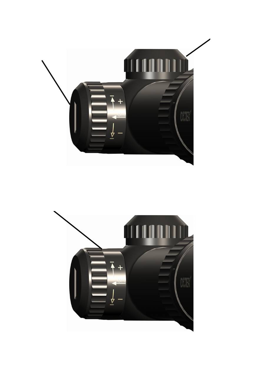
Inbetriebnahme
Einlegen der Batterie
Zuerst ist die Batteriefachkappe (1) abzuschrauben. Dann eine Lithium-Batterie CR2032
(Lieferumfang) mit der Plus-Seite nach oben auf das Batteriefach legen und in der Mitte
eindrücken bzw. einklicken. Die Beschriftung der Knopfzelle muss lesbar sein.
Entnehmen der Batterie
Zuerst muss die Batteriefachkappe (1) abgeschraubt werden. Nun kann die Knopfzelle
entnommen werden, indem die Zelle an deren Rand nach unten gedrückt wird, bis die
Batterie ausklinkt und übersteht.
Ein- / Ausschalten der Absehenbeleuchtung
Zum Einschalten der Absehnbeleuchtung wird die Steuereinheit (2) mit zwei Fingern
gefasst und herausgezogen. Im angeschalteten Zustand wird eine rote Markierung
sichtbar und informiert über den Betriebszustand des Zielfernrohres.
Durch Eindrücken der Steuereinheit (2) wird die Absehenbeleuchtung ausgeschaltet.
Helligkeitssteuerung der Absehenbeleuchtung
DOCTERbasic Zielfernrohre sind mit einem dimmbaren Tagesleuchtabsehen ausgestat-
tet. Die Intensitätseinstellung erfolgt über eine anschlagbegrenzte Auf- und Abwärtsbe-
wegung der Steuereinheit (2). Um die Leuchtintensität zu erhöhen wird die Steuereinheit
in Richtung (
+
) Markierung bewegt und gehalten. Um die Leuchtintensität zu verringern,
wird die Steuereinheit in Richtung (
–
) Markierung bewegt und gehalten. Bei Erreichen
der minimalen oder maximalen Endstellung blinkt das Leuchtabsehen. Nach dem los-
lassen der Steuereinheit ist die eingestellte Helligkeit fixiert.
Automatische Abschaltung
Wenn innerhalb einer Zeitspanne von etwa 3 Stunden die Steuereinheit (2) nicht betätigt
wird, schaltet sich die Absehenbeleuchtung automatisch ab. Um die Absehenbeleuch-
tung wieder zu aktivieren, wird die Steuereinheit (2) aus- und eingeschaltet oder die In-
tensitätseinstellung betätigt.
Memory – Funktion
Die Elektronik der Absehenbeleuchtung verfügt über eine Speicherfunktion. Der vor dem
Ausschalten zuletzt eingestellte Helligkeitswert wird gespeichert und steht nach erneu-
tem Einschalten sofort zur Verfügung.
Batteriewarnung
Wenn eine niedrige Batteriespannung festgestellt wurde, erfolgt eine Warnung durch
ständiges Blinken.

Montage
DOCTERbasic Zielfernrohre besitzen einen 30 mm Mittelrohrdurchmesser und sind für
eine Ringmontage ausgelegt. Die Auswahl der richtigen Montage erfolgt auf Grundlage
des Waffentyps. Der Büchsenmacher oder Fachhändler vor Ort wird sie gerne zur opti-
malen Montagevariante beraten.
Absehenverstellung
Zur Einstellung des Absehens werden die beiden Schutzkappen (3) von den Domen der
Absehenverstellung abgeschraubt. Durch Drehen der darunter liegenden Griffelemente
wird die Treffpunktlage verändert, und zwar am oberen Dom für die Höhe und am rech-
ten Dom für die Seite.
Höhenverstellung (H) (4)
Das Drehen der Griffelemente in Pfeilrichtung bewirkt eine Verschiebung des Treff-
punkts nach oben.
Seitenverstellung (R) (5)
Das Drehen der Griffelemente in Pfeilrichtung bewirkt eine Verschiebung des Treff-
punkts nach rechts.
Das Ende des Verstellbereiches ist durch Anschläge spürbar. Um eine zufällige Verstel-
lung des Absehens zu vermeiden und Wasserdichtheit zu gewährleisten, sind die
Schutzkappen (3) stets wieder auf die beiden Dome aufzuschrauben. Dabei ist auf den
Sitz der Dichtringe (6) zu achten.
Um ein schnelles Auffinden der „eingeschossenen“ Nulllage des Absehens bei Verwen-
dung unterschiedlicher Munition oder Laborierungen zu gewährleisten, kann die Skalen-
scheibe (7) nach Lösen der Kreuzschlitzschraube (8) so gedreht werden, daß sich beide
Indexmarken (9) gegenüberstehen.
Der Verstellbereich für die Treffpunktkorrektur ist gut bemessen. Sollte die Skalenteilung
dennoch nicht ausreichen, empfehlen wir Ihnen die Montierung des Zielfernrohres vom
Büchsenmacher überprüfen zu lassen.
Vergrößerungswechsel
Je nach Schussentfernung und Lichtverhältnissen lässt sich die geeignete Vergrößerung
durch drehen des Varioringes (10) mühelos einstellen.
Zur besseren Orientierung sind die wichtigsten Vergrößerungswerte auf dem Varioring
(10) graviert, wobei auch jede beliebige Zwischenvergrößerung bei gleichbleibender
Bildqualität, Sehschärfe und absolut unveränderter Treffpunktlage stufenlos einstellbar
ist.
Einstellung der Sehschärfe
Die Sehschärfe wird durch Drehen des äußeren Okularringes (11) eingestellt. Ein even-
tueller Augenfehler ist dann ausgeglichen, wenn bei entspanntem Sehen das Absehen
scharf wahrgenommen wird.
Es kann ein Augenfehlerausgleich von
±
2,5 Dioptrie vorgenommen werden.

Die Scharfeinstellung sollte prinzipiell bei der höchsten Vergrößerung vorgenommen
werden, da hierbei, bedingt durch die maximale Auflösung, die Sehschärfe am besten
beurteilt werden kann. Der spätere Wechsel der Vergrößerung ändert die vorgenomme-
ne Scharfeinstellung nicht.
Zubehör
Eine der Schutzkappen der Absehenverstellung ist konstruktiv größer gestaltet. Sie dient
mittels eines Magneten zur Aufnahme einer Reservebatterie im Format CR 2032.
Zum Schutz der äußeren Optikteile werden miteinander verbundene Schutzkappen ge-
liefert.
Zum Schutz vor Seitenlicht kann auf Wunsch eine Teleskopgummilichtschutzblende ge-
liefert werden, die gleichzeitig den richtigen Augenabstand zum Okular gewährleistet
und einen etwaigen Rückstoß dämpft.
Pflege
Das Gerät sollte gegen größere Verschmutzung geschützt werden
Die Optikflächen sollten gegebenenfalls mit einem weichen, sauberen Tuch oder Haar-
pinsel vorsichtig gesäubert werden.
Starke Verschmutzungen sollten mit destilliertem Wasser entfernt werden, weil es sonst
zu Kalkablagerungen auf den Oberflächen kommen kann. Zum Entfernen von Fettrück-
ständen auf den Linsen kann Spiritus oder handelsübliches Fensterreinigungsmittel
verwendet werden.
Es wird darauf hingewiesen, daß das Entfernen von Teilen des Zielfernrohres, zum Ver-
lust der Dichtigkeit und der Stickstofffüllung des Gerätes führen kann.
Bei etwaigen funktionsbeeinträchtigenden Beschädigungen muss das Gerät an eine au-
torisierte Servicewerkstatt eingesandt werden.
Information regarding the disposal of sighting mechanisms with
electronic portion
Sighting mechanisms, which are equipped with an
illuminated reticle and thus, owing to their design,
exhibit an electronic portion when they are worn, may
not me mixed with normal domestic waste
. Take these
products to the corresponding collection points, where
they will be accepted without charges for due han-
dling, recovery and recycling. The due disposal of this product at
the corresponding collection points serves the protection of the
environment and prevents possible harmful effects on man and
the environment, which may arise from the incorrect handling of
waste.
Information regarding the disposal of batteries in sighting mechanisms
Batteries may not be disposed of together with domes-
tic waste. Please dispose of spent batteries via the
reacceptance and recycling system intended for this
purpose. The consumer is legally obligated to turn in
discharged batteries that can no longer be used. They
are taken back at designated collection points.

General information
DOCTER
®
basic
rifle scopes constitute excellent target sights of state-of-the-art design.
Sound workmanship, high optical performance, an appealing design and functional reli-
ability even under extreme weather conditions will turn your
DOCTER
®
basic
rifle scopes
into indispensable companions.
Scope of delivery
•
1x transparent protective cap
•
2x battery CR 2032
•
Operating instructions
•
Guarantee card
Technical specifications
Model
1-4x24
1,5-6x42
2.5-10x50
3-12x56
Magnification
1x to 4x
1,5x to 6x
2.5x to 10x
3x to 12x
∅
Lens opening [mm]
24
42
50
56
∅
Centre tube [mm
30
∅
Lens tube [mm]
30
48
56
62
Overall length [mm]
279
323
345
376
Weight [g]
490
560
640
680
∅
Exit pupil [mm]
15 to 6.0
15, to 7,0
15 to 4.9
15 to 4.7
Field of view in m at
100 metres
31.0 to 10.6
19,1 to 7
11.3 to 4.2
9.4 to 3.5
Parallax-free observa-
tion distance [m]
100
Eye point [mm]
>90
Adjustment value of the
height and lateral ad-
justment
[cm at 100m]
2.0
1,0
1.0
1.0
Total adjustment range
for height and side
[cm at 100 m]
320
210
125
100
Eye deficiency com-
pensation
±
2,5
Function temperature
range
-25
°
C to +40
°
C
Storage temperature
range
-40
°
C to +55
°
C
Water tightness
Water tight up to 1 m

Initial operation
Inserting the battery
First of all, unscrew the cap of the battery compartment (1). Then place a lithium battery
CR2032 (included in the scope of supply) with the positive terminal pointing upwards
onto the battery compartment and depress in the centre until it engages. The inscription
on the button cell must be legible.
Removing the battery
First of all, unscrew the cap of the battery compartment (1). Now the button cell can be
removed by pushing down on the edge of the cell until the battery disengages and pro-
trudes.
Switching the reticle illumination on / off
To switch on the reticle illumination, take hold of the control unit (2) with two fingers and
pull it out. When it is switched on, a red marking is visible and provides information
about the operating status of the rifle scope.
Pushing in the control unit (2) switches off the reticle illumination.
Brightness control of the reticle illumination
DOCTERbasic rifle scopes are equipped with a dimmable daylight illuminated reticle.
The intensity is adjusted via an up and down movement of the control unit (2) that is lim-
ited by stoppers. To increase the illumination intensity, the control unit is moved in direc-
tion of the (
+
) marking and held there. To reduce the illumination intensity, the control
unit is moved in direction of the (
–
) marking and held there. On reaching the minimum or
maximum end position, the illuminated reticle starts to blink. The set brightness is re-
tained by releasing the control unit.
Automatic deactivation
If the control unit (2) is not activated within a period of approximately 3 hours, the reticle
illumination switches off automatically. To reactivate the reticle illumination, switch the
control unit (2) off and on or activate the intensity adjustment.
Memory function
The electronics of the reticle illumination is equipped with a memory function. The
brightness value set last before the device was switched off is saved and is immediately
available when the device is switched on again.
Battery warning
If a low battery voltage has been detected, a warning is given by constant blinking.

Installation
DOCTERbasic rifle scopes exhibit a 30 mm centre tube diameter and are designed for
ring installation. The correct type of installation is selected based on the weapon model.
Your local gunsmith or specialist dealer will be happy to advice you with regard to the
optimum installation version.
Reticle adjustment
To adjust the reticle, the two protective caps (3) are unscrewed from the domes of the
reticle adjustment. By turning the handle elements located underneath, the hit point posi-
tion is changed. The top dome is used to change the height setting and the right-hand
dome to change the lateral setting.
Height adjustment (H) (4)
Turning the handle elements in direction of the arrow causes the hit point to be moved
upwards.
Lateral adjustment (R) (5)
Turning the handle elements in direction of the arrow causes the hit point to be moved to
the right.
The end of the adjustment range is noticeable because of the stoppers. To prevent an
accidental adjustment of the reticle and to guarantee water tightness, the protective caps
(3) must always be screwed back onto the two domes. Pay attention to the seat of the
sealing rings (6) when doing so.
To ensure that the "zeroed-in" zero position of the reticle can be quickly found when us-
ing different ammunitions or fillings, the scale disc (7) can be turned such after undoing
the cross-head screw (8) that both index marks (9) are facing each other.
The adjustment range for the hit point correction is well dimensioned. Should the scale
division nevertheless prove insufficient, we recommend you have the installation of the
rifle scope checked by a gunsmith.
Change of magnification
Depending on shot distance and light conditions, the suitable magnification can be easily
set by turning the variable ring (10).
To improve orientation, the most important magnification values are engraved on the
variable ring (10). At the same time, it is possible to set any intermediate magnification in
an infinitely variable manner at consistent image quality, visual acuity and absolutely
unchanged hit point position.
Setting the visual acuity
The visual acuity is set by turning the outer eyepiece ring (11). Possible eye deficiencies
have been compensated as soon as the reticle is perceived sharply during relaxed view-
ing.
An eye deficiency compensation of
±
2.5 dioptres can be effected.

Focussing should in principal be effected at the highest magnification, as this is when,
due to the maximum resolution, the visual acuity can be judged best. A later change in
magnification does not change any previously adjusted focussing.
Accessories
One of the protective caps of the reticle adjustment is designed somewhat larger. It
serves to accommodate a spare battery format CR 2032 by means of a magnet.
Protective caps that are joined to each other are included in the supply to protect the
external parts of the optical systems.
As protection against sidelight, a rubber telescope light protection shield can be supplied
upon request. This shield at the same time guarantees the correct eye distance to the
eye piece and attenuates any recoil.
Care
The device should be protected against heavy soiling.
If necessary, the lens surfaces should be carefully cleaned with a soft, clean cloth or hair
brush.
Heavy soiling should be removed with distilled water to prevent any calcifications on the
surfaces. To remove greasy residues on the lenses, it is possible to use methylated spir-
its or a commercially available window cleaning agent.
We would like to point out that detaching parts of the rifle scope may lead to a loss of
water tightness and of the device's nitrogen filling.
In case of function-impairing damage, the device must be sent to an authorised service
workshop.
Consignes d'élimination des dispositifs de visée usagés contenant des éléments
électroniques
Il est interdit de mettre les dispositifs de visée équipés
d'un viseur lumineux et donc d'éléments électroniques
de par leur conception dans les déchets ménagers
habituels une fois qu'ils sont en fin de vie. Emportez-
les aux points de collecte concernés où ils seront ré-
cupérés sans frais pour être traités, récupérés et recy-
clés dans les règles. La mise en déchetterie dans les règles de
ce produit aux points de collecte prévus permet de protéger l'en-
vironnement et empêche d'éventuels effets nocifs sur l'homme et
l'environnement pouvant résulter de leur manipulation inadé-
quate.
Consignes d'élimination des piles des dispositifs de visée usagés
Ne pas jeter les piles dans les déchets ménagers.
Veuillez remettre les piles usagées aux services de
collecte et de recyclage prévus à cet effet. Le con-
sommateur est légalement tenu d'y déposer les piles
déchargées et devenues inutilisables. Elles sont re-
prises à des points de collecte signalés

Informations générales
Les lunettes de visée
DOCTER
®
basic
constituent d’excellents systèmes optiques de
type extrêmement pointu.
Avec leur robustesse, leur performance optique élevée, leur design esthétique et leur
sécurité fonctionnelle, vos lunettes de visée
DOCTER
®
basic
vous deviendront indis-
pensables même dans des conditions météorologiques extrêmes.
Pièces fournies
•
1 capuchon protecteur transparent
•
2 piles CR 2032
•
Mode d'emploi
•
Carte de garantie
Fiche technique
Modèle
1-4x24
1,5-6x42
2,5-10x50
3-12x56
Grossissement
1x à 4x
1,5x à 6x
2,5x à 10x
3x à 12x
∅
Ouverture d’objectif
[mm]
24
42
50
56
∅
Tube central [mm]
30
∅
Tube d'objectif [mm]
30
48
56
62
Longueur totale [mm]
279
323
345
376
Poids [g]
490
560
640
680
∅
Pupille de sortie [mm]
15 à 6,0
15, à 7,0
15 à 4,9
15 à 4,7
Champ visuel en m à
100 mètres
31,0 à 10,6
19,1 à 7
11,3 à 4,2
9,4 à 3,5
Distance d'observation
sans parallaxe [m]
100
Point oculaire [mm]
>90
Valeur de réglage du
réglage
en hauteur et latéral
[cm à 100 m]
2,0
1,0
1,0
1,0
Plage de réglage glo-
bale
en hauteur et latérale-
ment
[cm à 100 m]
320
210
125
100
Correction des défauts
de vision
±
2,5
Plage de température
opérationnelle
-25
°
C à +40
°
C
Plage de température
de stockage
-40
°
C à +55
°
C
Etanchéité
Etanches à l'eau à 1 m

Mise en marche
Insertion de la pile
Dévisser d'abord le couvercle du compartiment à pile (1). Mettre ensuite une pile au li-
thium CR2032 (fournie) avec le pôle plus tourné vers le haut dans le compartiment puis
appuyer dessus au centre pour l'enclencher. L'inscription de la pile bouton doit être li-
sible.
Retrait de la pile
Il faut d'abord dévisser le couvercle du compartiment à pile (1). On peut maintenant reti-
rer la pile bouton en l'enfonçant sur son bord jusqu'à ce qu'elle se désenclenche et res-
sorte.
Mise en marche/arrêt de l'éclairage du viseur
Pour allumer l'éclairage du viseur, saisir l'unité de commande (2) à deux doigts et tirer
dessus. En position éclairée, un marquage rouge apparaît et signale l'état de fonction-
nement de la lunette de visée.
L'éclairage du viseur se coupe en enfonçant l'unité de commande (2).
Contrôle de luminosité de l'éclairage du viseur
Les lunettes de visée DOCTERbasic sont équipées d'un viseur modulable pour éclai-
rage diurne. L'intensité se règle en montant et en descendant l'unité de commande (2)
entre les butées de limitation. Pour augmenter l'intensité lumineuse, amener l'unité de
commande vers le marquage (
+
) et l'arrêter là. Pour réduire l'intensité lumineuse, ame-
ner l'unité de commande vers le marquage (
+
) et l'arrêter là. Le viseur lumineux clignote
lorsqu'on atteint la position extrême minimale ou maximale. La luminosité réglée est
fixée lorsqu'on relâche l'unité de commande.
Coupure automatique
Si l'unité de commande (2) n'est pas actionnée pendant une durée d'environ 3 se-
condes, l'éclairage du viseur se coupe automatiquement. Pour réactiver l'éclairage du
viseur, actionner ou arrêter l'unité de commande (2) ou actionner le réglage d'intensité.
Fonction mémoire
Le système électronique de l'éclairage du viseur a une fonction mémoire. La dernière
valeur de luminosité réglée avant l'arrêt est enregistrée et est immédiatement disponible
à la remise en marche.
Alerte pile
Quand une faible tension de la pile a été détectée, une alerte est émise via un clignote-
ment constant.

Montage
Les lunettes de visée DOCTERbasic ont un tube central d'un diamètre de 30 mm et
sont conçues pour un montage annulaire. La sélection du montage adéquat se fait sui-
vant le type d'arme. Votre armurier ou revendeur local vous informera volontiers de la
meilleure option de montage.
Réglage du viseur
Pour régler le viseur, dévisser les deux capuchons protecteurs (3) des mandrins du ré-
gleur de viseur. En tournant les éléments préhenseurs qui se trouvent dessous, vous
pouvez modifier le point d'impact de la cible, et ce sur le mandrin supérieur pour la hau-
teur et le mandrin droit pour les côtés.
Réglage de la hauteur (H) (4)
La rotation des éléments préhenseurs dans le sens de la flèche provoque un décalage
du point d'impact vers le haut.
Réglage latéral (R) (5)
La rotation des éléments préhenseurs dans le sens de la flèche provoque un décalage
du point d'impact vers la droite.
Le bout de la plage de réglage est perceptible grâce à des butées. Pour éviter un déré-
glage du viseur et garantir l'étanchéité à l'eau, il faut toujours revisser les capuchons
protecteurs (3) sur les deux mandrins. Veiller alors à ce que les bagues d'étanchéité (6)
soient bien en place.
Pour trouver rapidement la position zéro "intégrée" du viseur si on utilise différents pro-
jectiles ou munitions, on peut tourner le disque gradué (8) après avoir dévissé la vis cru-
ciforme (8) de manière à ce que les deux marques d'indexation (9) se recouvrent.
La plage de réglage pour la correction du point d'impact est largement dimensionnée. Si
la graduation n'était néanmoins pas suffisante, nous conseillons de faire contrôler le
montage de la lunette de visée par un armurier.
Changement de grossissement
Suivant la distance de tir et les conditions lumineuses, un agrandissement approprié
peut se régler facilement en tournant la molette (10).
Pour permettre une meilleure orientation, les grossissements les plus importants sont
gravés sur la molette (10), sachant que n'importe quel grossissement intermédiaire peut
se régler en progressif avec une qualité d'image et une acuité identiques sans aucune
modification du point d'impact.
Réglage de l'acuité visuelle
L'acuité visuelle se règle en tournant la bague extérieure de l'oculaire (11). Un éventuel
défaut de vision est corrigé lorsqu'on perçoit nettement l'objectif quand on regarde de
manière détendue.
Une correction de défaut de vision de
±
2,5 dioptries peut être effectuée.

Le réglage de l'acuité doit en principe être fait au plus fort grossissement car c'est alors
qu'on peut le mieux évaluer l'acuité visuelle du fait de la définition maximale. Le chan-
gement ultérieur de grossissement ne modifie pas le réglage d'acuité effectué.
Accessoires
Un des capuchons du régleur de viseur est de plus grande taille. Il peut contenir une pile
de réserve de format CR 2032 maintenue par un aimant.
Des capuchons emboîtés sont fournis pour la protection des pièces optiques exté-
rieures.
Pour se protéger de la lumière latérale, une œillère télescopique en caoutchouc peut
être fournie sur demande ; elle garantit en même temps une bonne distance entre les
yeux et l'oculaire et amortit l'éventuel recul.
Entretien
L'appareil doit être protégé des grosses salissures.
Les surfaces optiques doivent le cas échéant être nettoyées soigneusement avec un
chiffon doux et humide ou au pinceau.
Les grosses impuretés doivent être éliminées à l’eau distillée sinon des dépôts calcaires
peuvent se former sur les surfaces. Pour enlever les résidus de graisse sur les lentilles,
vous pouvez utiliser de l'alcool ou du nettoyant pour vitres du commerce.
Il est signalé que le retrait de pièces de la lunette de visée peut entraîner une perte
d'étanchéité et de l'azote contenu dans l'appareil.
En cas d’éventuelles détériorations nuisant au fonctionnement, il faut envoyer l'appareil
à un atelier de SAV agréé.
Información relativa a la eliminación de sistemas de puntería con componente
electrónico
Los sistemas de puntería que disponen de una
retícula iluminada y, por ello, debido a su propio
diseño, de un componente electrónico, cuando ya no
se utilicen, no deberán depositarse en la basura
doméstica habitual. Para que el tratamiento, la
recuperación y el reciclado de estos productos sean
los correctos, deberán llevarse a los centros de recogida
correspondientes donde podrán depositarse de forma gratuita.
La eliminación de residuos de este producto en los
correspondientes lugares de recogida tiene como objeto la
protección del medio ambiente, evitando, además, posibles
efectos nocivos sobre las personas y el entorno provocados por
un tratamiento incorrecto de los residuos.
Información relativa a la eliminación de pilas de dispositivos de mira
Las pilas no deben depositarse en la basura
doméstica. Las pilas agotadas deberán llevarse al
sistema de recogida y reciclado previsto para este fin.
El consumidor está legalmente obligado a entregar las
pilas agotadas que ya no pueden utilizarse más. La
recogida se realizará en los puntos indicados para
este fin.

Información general
Las miras telescópicas
DOCTER
®
basic
son extraordinarios sistemas ópticos de
modernísima construcción.
Su sólida ejecución, su alto rendimiento óptico, su atractivo diseño y la seguridad de su
función incluso en condiciones climáticas extremas harán que sus miras telescópicas
DOCTER
®
basic
le resulten indispensables.
Ámbito de suministro
•
1 caperuza de protección transparente
•
2 pilas CR 2032
•
Manual de instrucciones
•
Tarjeta de garantía
Datos técnicos
Modelo
1-4x24
1,5-6x42
2,5-10x50
3-12x56
Aumento
1x a 4x
1,5x a 6x
2,5x a 10x
3x a 12x
∅
de apertura del
objetivo [mm]
24
42
50
56
∅
del tubo central [mm
30
∅
del tubo del objetivo
[mm]
30
48
56
62
Longitud total [mm]
279
323
345
376
Peso [g]
490
560
640
680
∅
del anillo ocular [mm]
15 a 6,0
15, a 7,0
15 a 4,9
15 a 4,7
Campo visual a 100
metros de distancia en
m
31,0 a 10,6
19,1 a 7
11,3 a 4,2
9,4 a 3,5
Distancia de
observación sin paralaje
[m]
100
Punto ocular [mm]
>90
Valor de ajuste en
vertical y horizontal [en
cm a 100 m]
2,0
1,0
1,0
1,0
Valor de ajuste
completo en vertical y
horizontal [en cm a 100
m]
320
210
125
100
Compensación de
defectos visuales
±
2,5
Área de temperatura
funcional
-25
°
C a +40
°
C
Área de temperatura de
almacenamiento
-40
°
C a +55
°
C

Impermeabilidad
Impermeable al agua a 1 m

Puesta en marcha
Colocación de la pila
En primer lugar, desatornille la tapa del compartimento para la pila (1). A continuación,
coloque una pila de litio CR2032 (incluida en el ámbito de suministro) en el
compartimento, de forma que el lado positivo quede hacia arriba y presiónela y encájela
por el centro. Debe poder leerse la inscripción de la pila.
Extracción de la pila
En primer lugar, desatornille la tapa del compartimento para la pila (1). Ahora, ya puede
sacar la pilla presionando hacia abajo el borde de la pila hasta que se suelte y
sobresalga.
Conexión y desconexión de la iluminación de la retícula
Para conectar la iluminación de la retícula, deberá sujetar y sacar con dos dedos la
unidad de control (2). Cuando esté conectada, podrá verse una marca roja que
informará sobre el estado de funcionamiento de la mira.
La iluminación de la retícula se desconecta presionando la unidad de control (2).
Ajuste de la iluminación de la retícula
Las miras telescópicas DOCTERbasic están equipadas con una retícula para luz diurna
regulable. La intensidad se regula moviendo hacia arriba o hacia abajo la unidad de
control (2). Este movimiento está limitado con topes. Para aumentar la intensidad de
iluminación, hay que mover y fijar la unidad de control en dirección a la marca (
+
). Para
disminuir la intensidad, hay que mover y fijar la unidad de control en dirección a la
marca (
–
). Cuando se alcanza la posición final mínima o máxima, la retícula se ilumina
de forma intermitente. Al soltar la unidad de control queda fijada la claridad configurada.
Desconexión automática
Si en el plazo de tres horas no se ha accionado la unidad de control (2), la iluminación
de la retícula se desconecta de forma automática. Para volver a activar la iluminación,
hay que activar o desactivar la unidad de control (2) o accionar el ajuste de intensidad.
Función de memoria
El sistema electrónico de la iluminación de la retícula dispone de una función de
memoria. El último valor de iluminación configurado antes de la desconexión queda
guardado, estando de inmediato a disposición en el siguiente encendido.
Advertencia de carga baja de la pila
Si se constata una carga baja de la pila, se produce una advertencia con una luz
intermitente.

Montaje
Las miras telescópicas DOCTERbasic poseen un diámetro de tubo central de 30 mm y
están diseñadas para un montaje en anillo. La elección del montaje correcto se realizará
dependiendo del tipo de arma. El armero o el comercial especializado le asesorarán
directamente sobre la mejor variante de montaje.
Ajuste de la retícula
Para ajustar la retícula, se destornillan las dos caperuzas protectoras (3) de los domos
de ajuste. Haciendo girar los elementos de agarre inferiores puede modificarse la
posición del punto de impacto: en el domo superior se modifica la altura y en el domo
derecho la posición horizontal.
Ajuste vertical (H) (4)
Girando los elementos de agarre en dirección de la flecha se consigue desplazar la
posición del punto de impacto hacia arriba.
Ajuste horizontal (R) (5)
Girando los elementos de agarre en dirección de la flecha se consigue desplazar la
posición del punto de impacto hacia la derecha.
El final del área de ajuste se hace notar con topes. Para evitar un desajuste accidental
de la retícula y para garantizar la debida impermeabilidad al agua, hay que atornillar
siempre de nuevo las caperuzas protectoras (3) a ambos domos, prestando atención a
que los anillos de junta (6) estén correctamente fijados.
Para asegurar una rápida localización del punto de ajuste de la retícula tras la utilización
de diferentes tipos de munición o recargas, el cuadrante (7) puede girarse tras soltar el
tornillo de estrella (8), de forma que las dos marcas de índice (9) coincidan.
El área de ajuste para la corrección del punto de impacto es suficientemente grande
para las necesidades prácticas. Sin embargo, si alguna vez la escala resultara
insuficiente, recomendamos que solicite a su armero que compruebe el montaje de su
mira telescópica.
Cambio de aumento
Dependiendo de la distancia de tiro y de la luz existente, el aumento puede ajustarse
fácilmente girando el anillo vario (10).
Para facilitar la orientación, en el anillo vario (10) aparecen grabados los valores de
aumento más importantes pudiendo, ajustarse igualmente de forma directa cualquier
aumento intermedio manteniéndose la misma calidad de imagen, agudeza visual y sin
variar en absoluto la posición del punto de impacto.
Ajuste de la agudeza visual
La agudeza visual se ajusta girando el anillo ocular exterior (11). Un posible defecto
visual queda compensado cuando, al mirar de forma relajada, se percibe la retícula de
forma nítida.
Puede alcanzarse una compensación de defectos visuales de
±
2,5 dioptrías.

El ajuste de la agudeza visual debería realizarse, en principio, con el máximo aumento
dado que, debido a la máxima resolución, es como mejor puede valorarse la agudeza
visual. Si, posteriormente, se modifica el aumento, el ajuste de la agudeza no se ve
influenciado.
Accesorios
Una de las caperuzas de protección del ajuste de la retícula se ha diseñado con un
tamaño mayor. Gracias al imán, puede alojar una pila de repuesto de formato CR 2032.
Para proteger los componentes ópticos exteriores, se suministran caperuzas de
protección unidas entre sí.
Para proteger de la luz lateral, previa petición, también puede suministrarse un
diafragma protector de caucho que garantiza la distancia correcta del ojo al ocular y, a
la vez, amortigua los posibles retrocesos del arma.
Cuidado
El aparato debe estar protegido de suciedad mayor.
En caso necesario, las superficies ópticas deberán limpiarse con cuidado con un paño
suave y limpio o con un pincel.
En caso de fuerte suciedad, esta deberá eliminarse con agua destilada porque, de otro
modo, puede depositarse cal en las superficies. Para retirar restos de grasa en las
lentes puede utilizarse alcohol o un limpiador de cristales habitual en el mercado.
Hay que indicar que, al retirar componentes de la mira telescópica, puede producirse la
pérdida de impermeabilidad y del relleno de hidrógeno del aparato.
En caso de daños que afecten a los elementos funcionales, el aparato deberá enviarse
a un taller de servicio autorizado para su reparación.
Указания
по
утилизации
прицельных
устройств
с
электронными
компонентами
Прицельные
устройства
,
оборудованные
подсветкой
прицельной
марки
и
содержащие
поэтому
обусловленные
конструкцией
электронные
компоненты
,
при
утилизации
не
подлежат
смешению
с
обычным
бытовым
мусором
.
Сдавайте
такие
изделия
для
надлежащей
обработки
,
вторичного
использования
и
переработки
в
соответствующие
пункты
сбора
,
где
их
принимают
на
безвозмездной
основе
.
Надлежащая
утилизация
данного
изделия
в
соответствующем
пункте
сбора
способствует
защите
окружающей
среды
и
не
допускает
возможных
вредных
воздействий
на
человека
и
его
окружение
,
к
которым
может
привести
ненадлежащее
обращение
с
мусором
.
Указания
по
утилизации
батареек
прицельных
устройств
Батарейки
нельзя
отправлять
в
бытовой
мусор
.
Пожалуйста
,
утилизируйте
использованные
батарейки
посредством
предусмотренной
для
этого
системы
приема
и
переработки
.
Пользователь
по
закону
обязан
сдавать
разряженные
и
более
не
пригодные
к
использованию
батарейки
.
Прием
осуществляется
в
официальных
пунктах
сбора
.

Общие
сведения
Оптические
прицелы
DOCTER
®
basic
являются
превосходными
оптическими
прицельными
устройствами
самой
современной
конструкции
.
Прочные
материалы
,
высокая
оптическая
производительность
,
привлекательный
дизайн
и
функциональность
даже
в
экстремальных
погодных
условиях
сделают
ваш
оптический
прицел
DOCTER
®
basic
просто
незаменимым
.
Комплектация
•
1x
прозрачный
защитный
колпачок
•
2x
батарейки
CR 2032
•
Руководство
по
эксплуатации
•
Гарантийный
талон
Технические
характеристики
Модель
1-4x24
1,5-6x42
2,5-10x50
3-12x56
Увеличение
от
1x
до
4x
от
1,5x
до
6x
от
2,5
до
10x
от
3x
до
12x
∅
отверстия
объектива
[
мм
]
24
42
50
56
∅
средней
трубки
[
мм
]
30
∅
трубки
объектива
[
мм
]
30
48
56
62
Общая
длина
[
мм
]
279
323
345
376
Масса
[
г
]
490
560
640
680
∅
выходного
зрачка
[
мм
]
от
15
до
6,0
от
15
до
7,0
от
15
до
4,9
от
15
до
4,7
Поле
зрения
в
м
на
100
метрах
от
31,0
до
10,6
от
19,1
до
7
от
11,3
до
4,2
от
9,4
до
3,5
Дальность
наблюдения
без
параллакса
[
м
]
100
Центр
перспективы
[
мм
]
>90
Установочная
величина
вертикальной
и
горизонтальной
регулировки
[
см
на
100
м
]
2,0
1,0
1,0
Предел
регулировки
по
высоте
и
горизонту
[
см
на
100
м
]
320
125
100
Корректировка
дефектов
зрения
±
2,5
Диапазон
рабочих
температур
от
-25
°
C
до
+40
°
C
Диапазон
температур
хранения
от
-40
°
C
до
+55
°
C
Герметичность
Водонепроницаемость
1
м

Ввод
в
эксплуатацию
Установка
батареи
Сначала
отвинтить
колпачок
(1)
батарейного
отсека
.
Затем
положить
литиевую
батарейку
CR2032 (
входит
в
комплектацию
)
стороной
"
плюс
"
наверх
на
батарейный
отсек
и
,
надавив
посередине
,
вдавить
ее
до
щелчка
.
Надпись
на
элементе
питания
должна
быть
хорошо
видна
.
Вынимание
батарейки
Сначала
необходимо
отвинтить
колпачок
(1)
батарейного
отсека
.
Теперь
элемент
питания
может
быть
вынут
,
если
надавить
на
его
нижний
край
до
тех
пор
,
пока
батарейка
не
выскочит
со
щелчком
и
не
окажется
приподнятой
.
Включение
/
выключение
подсветки
прицельной
марки
Для
включения
подсветки
прицельной
марки
рычажок
управления
(2)
берется
двумя
пальцами
и
вытягивается
.
Во
включенном
состоянии
видна
красная
метка
,
информирующая
о
рабочем
состоянии
оптического
прицела
.
Подсветка
прицельной
марки
отключается
путем
нажатия
до
упора
на
рычажок
управления
(2).
Управление
яркостью
подсветки
прицельной
марки
Оптические
прицелы
DOCTERbasic
оборудованы
регулируемой
люминесцентной
подсветкой
прицельной
марки
.
Настройка
интенсивности
осуществляется
путем
ограниченного
упором
перемещения
рычажка
управления
(2)
вверх
и
вниз
.
Для
повышения
интенсивности
свечения
рычажок
управления
перемещается
в
направлении
отметки
(
+
)
и
удерживается
.
Для
уменьшения
интенсивности
свечения
рычажок
управления
перемещается
в
направлении
отметки
(
–
)
и
удерживается
.
По
достижении
минимального
или
максимального
конечного
положения
подсветка
прицельной
марки
замигает
.
После
того
,
как
рычажок
управления
будет
отпущен
,
настроенная
яркость
зафиксируется
.
Автоматическое
отключение
Если
в
течение
промежутка
времени
порядка
3
часов
рычажок
управления
(2)
не
задействуется
,
подсветка
прицельной
марки
автоматически
отключается
.
Для
нового
включения
подсветки
прицельной
марки
рычажок
управления
(2)
выключается
и
снова
включается
,
или
производится
регулировка
интенсивности
свечения
.
Функция
памяти
Электронная
система
подсветки
прицельной
марки
оборудована
функцией
памяти
.
Последнее
перед
выключением
настроенное
значение
яркости
сохраняется
и
обеспечивается
сразу
после
нового
включения
.
Предупреждение
о
низком
заряде
батарейки
При
обнаружении
низкого
напряжения
батареи
выдается
предупреждение
в
виде
постоянного
мигания
.

Монтаж
Оптические
прицелы
DOCTERbasic
обладают
диаметром
средней
трубки
в
30
мм
и
предназначены
для
монтажа
на
установочных
кольцах
.
Выбор
правильного
варианта
монтажа
производится
в
зависимости
от
типа
оружия
.
Инженеры
-
оружейники
или
сотрудники
местных
специализированных
магазинов
проконсультируют
вас
относительно
выбора
оптимального
варианта
монтажа
.
Регулировка
прицельной
марки
Для
настройки
прицельной
марки
оба
защитных
колпачка
(3)
отвинчиваются
от
выступов
регулировки
прицельной
марки
.
Вращая
расположенные
под
ними
регуляторные
ручки
,
можно
менять
положение
точки
попадания
,
верхний
выступ
обеспечивает
регулировку
по
высоте
,
а
правый
–
по
горизонту
.
Регулировка
по
высоте
(H) (4)
Вращение
регуляторных
ручек
в
направлении
стрелки
обеспечивает
смещение
точки
попадания
вверх
.
Регулировка
по
горизонту
(R) (5)
Вращение
регуляторных
ручек
в
направлении
стрелки
обеспечивает
смещение
точки
попадания
вправо
.
Достижение
предела
диапазона
регулировки
ощутимо
благодаря
упорам
.
Во
избежание
случайного
смещения
прицельной
марки
и
для
обеспечения
водонепроницаемости
защитные
колпачки
(3)
следует
всегда
привинчивать
обратно
к
этим
двум
выступам
.
При
этом
необходимо
следить
за
правильностью
посадки
уплотнительных
колец
(6).
Для
обеспечения
быстрого
нахождения
"
пристрелянной
"
нулевой
отметки
прицельной
марки
при
использовании
патронов
другого
типа
или
другого
лаборирования
,
можно
после
вывинчивания
винта
с
крестообразным
шлицем
(8)
повернуть
шкальный
диск
(7)
таким
образом
,
чтобы
обе
указательные
отметки
(9)
находились
друг
напротив
друга
.
Диапазон
регулировки
для
корректировки
точки
попадания
является
хорошо
выверенным
.
Если
же
,
тем
не
менее
,
деления
шкалы
окажутся
недостаточными
,
мы
рекомендуем
вам
обратиться
к
инженеру
-
оружейнику
для
проверки
монтажа
оптического
прицела
.
Регулировка
кратности
увеличения
В
зависимости
от
дальности
стрельбы
и
условий
света
подходящая
кратность
увеличения
может
быть
без
проблем
настроена
путем
вращения
регулировочного
колесика
(10).
Для
лучшей
ориентации
важнейшие
значения
кратности
выгравированы
на
регулировочном
колесике
(10),
при
этом
путем
плавной
регулировки
доступны
также
любые
промежуточные
значения
кратности
при
неизменном
качестве
изображения
,
резкости
и
абсолютно
неизменном
положении
точки
попадания
.
Регулировка
резкости
Резкость
настраивается
путем
вращения
внешнего
окулярного
кольца
(11).
Тем
самым
компенсируется
возможный
дефект
зрения
,
когда
при
ненапряженном
состоянии
глаза
прицельная
марка
воспринимается
четкой
.
Может
быть
обеспечена
компенсация
дефектов
зрения
в
±
2,5
диоптрии
.
В
принципе
,
настройка
резкости
должна
производиться
при
наибольшем
приближении
,
поскольку
в
этом
случае
резкость
может
быть
оценена
наилучшим
образом
за
счет

максимального
разрешения
.
Дальнейшее
изменение
приближения
не
меняет
настроенной
резкости
.
Принадлежности
Один
из
защитных
колпачков
регулировки
прицельной
марки
в
соответствии
с
конструкцией
имеет
несколько
больший
размер
.
Она
служит
для
хранения
запасной
батарейки
формата
CR 2032,
удерживаемой
магнитом
.
Для
защиты
внешних
деталей
оптики
в
комплектацию
включены
соединенные
друг
с
другом
защитные
колпачки
.
Для
защиты
от
бокового
света
по
желанию
в
комплектацию
может
быть
включена
телескопическая
резиновая
светозащитная
бленда
,
которая
одновременно
обеспечивает
правильное
расстояние
от
глаза
до
окуляра
и
амортизирует
отдачу
.
Уход
Устройство
следует
оберегать
от
сильного
загрязнения
.
Поверхности
оптики
следует
при
необходимости
осторожно
прочищать
мягким
чистым
платком
или
волосяной
кисточкой
.
Сильные
загрязнения
необходимо
удалять
дистиллированной
водой
,
поскольку
иначе
на
поверхностях
может
происходить
отложение
известкового
осадка
.
Для
удаления
пятен
от
жира
или
масла
на
линзах
можно
использовать
спирт
или
общеупотребительное
средство
для
мытья
стекол
.
Мы
подчеркиваем
,
что
демонтаж
деталей
оптического
прицела
может
привести
к
снижению
герметичности
и
наполнению
устройства
азотом
.
При
возможных
негативно
отражающихся
на
функциональности
повреждениях
необходимо
отправить
устройство
в
авторизованную
сервисную
мастерскую
.
