Ridgid SeekTech SR-20: instruction
Class: Power tools
Type:
Manual for Ridgid SeekTech SR-20

SeekTech
SR-20
GB p. 1
DE
p. 28
FR
p. 55
NL
p. 82
IT p. 109
ES
p. 136
PT
p. 163
DA
p. 191
NO
p. 218
PL p. 245
RU
p. 272
RIDGE TOOL COMPANY
Ridge Tool Company
1
Tools For The Professional
TM
seekTech sR-20
DANGER
GB
• The SR-20 is a diagnostic tool that senses electromagnetic
elds emitted by objects underground. It is meant to
SeekTech SR-20
aide the user in locating these objects by recognizing
characteristics of the eld lines and displaying them on
Operating Instructions
the screen. As electromagnetic eld lines can be distorted
and interfered with, it is important to verify the location
of underground objects before digging.
General Safety Information
• Several utilities may be underground in the same
WARNING! Read these instructions
area. Be sure to follow local guidelines and one-call
and the accompanying safety
service procedures.
booklet carefully before using
• Exposing the utility is the only way to verify its
this equipment. If you are
existence, location, and depth.
uncertain about any aspect of using this tool,
contact your RIDGID distributor for more
• Ridge Tool Co., its aliates and suppliers, will not be
liable for any injury or any direct, indirect, incidental
information.
or consequential damages sustained or incurred by
reason of the use of the SR-20.
Failure to understand and follow all
instructions may result in electric shock,
re, and/or serious personal injury.
In any correspondence, please give all the information shown
on the nameplate of your tool including model number and
SAVE THESE INSTRUCTIONS!
serial number.
CAUTION: Remove batteries entirely before shipping.
If you have any questions regarding the service or repair
of this machine, contact your Ridgid distributor, your local
Ridgid oce or Ridge Tool Europe at info.europe@ridgid.
com
2
Ridge Tool Company
Tools For The Professional
TM
seekTech sR-20
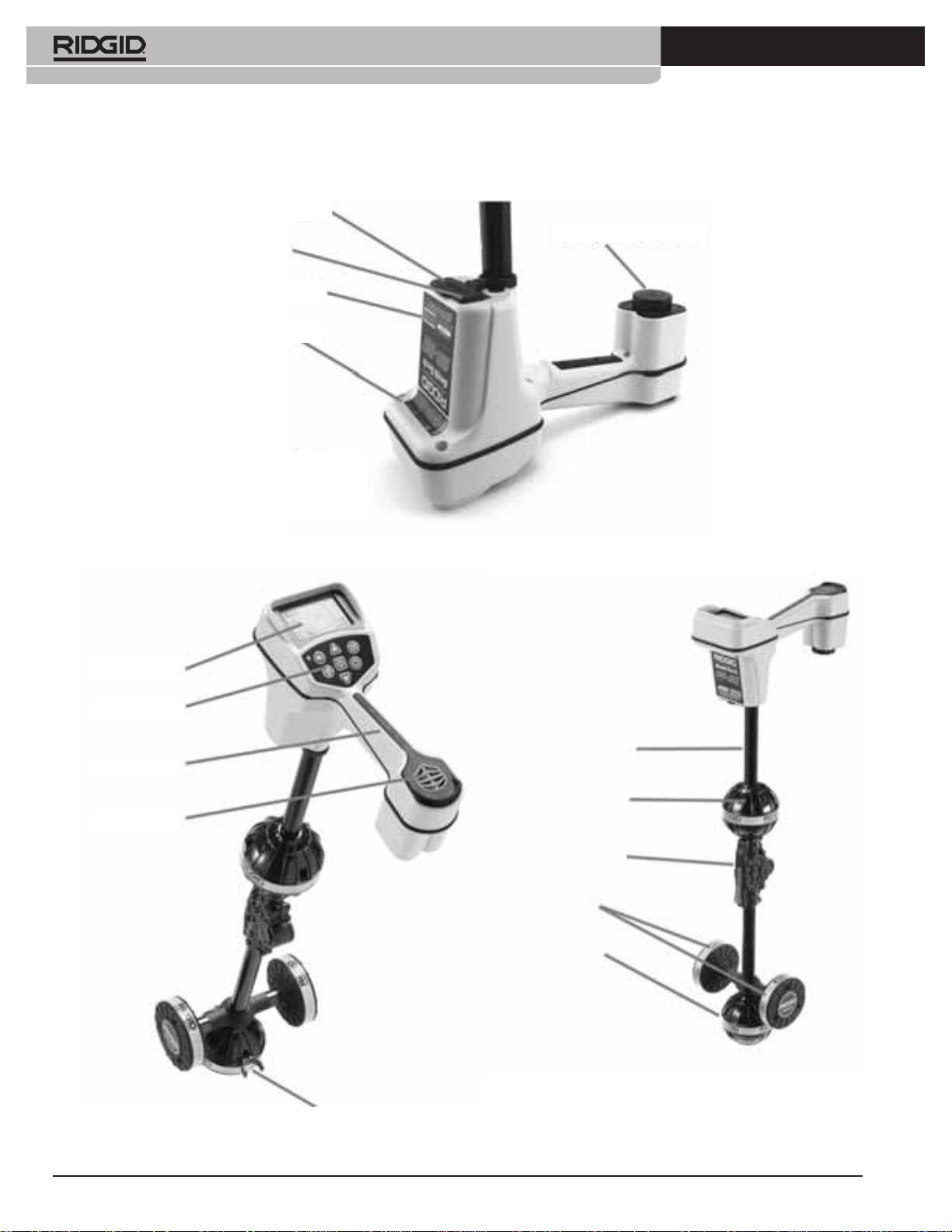
SR-20 Components
Serial Port Connector
Battery Compartment
USB Connector
Serial Number Label
Icon Reference
Note: USB/ Serial Ports are
for loading new software
Display Screen
Keypad
Antenna Mast
Handle
Upper Antenna
Node
Speaker
Folding Joint
Guidance
Antennas
Lower Antenna
Node
Folding Mast Snap
Figure 1: SR-20 Components
Ridge Tool Company
3
Tools For The Professional
TM
seekTech sR-20
Introduction to the SR-20
SR-20 Modes
The SR-20 operates in three distinct modes. They are:
Getting Started
1. Active Line Trace Mode, used when a chosen
frequency can be put onto a long conductor using a
Line Transmitter, for locating conductive pipes, lines,
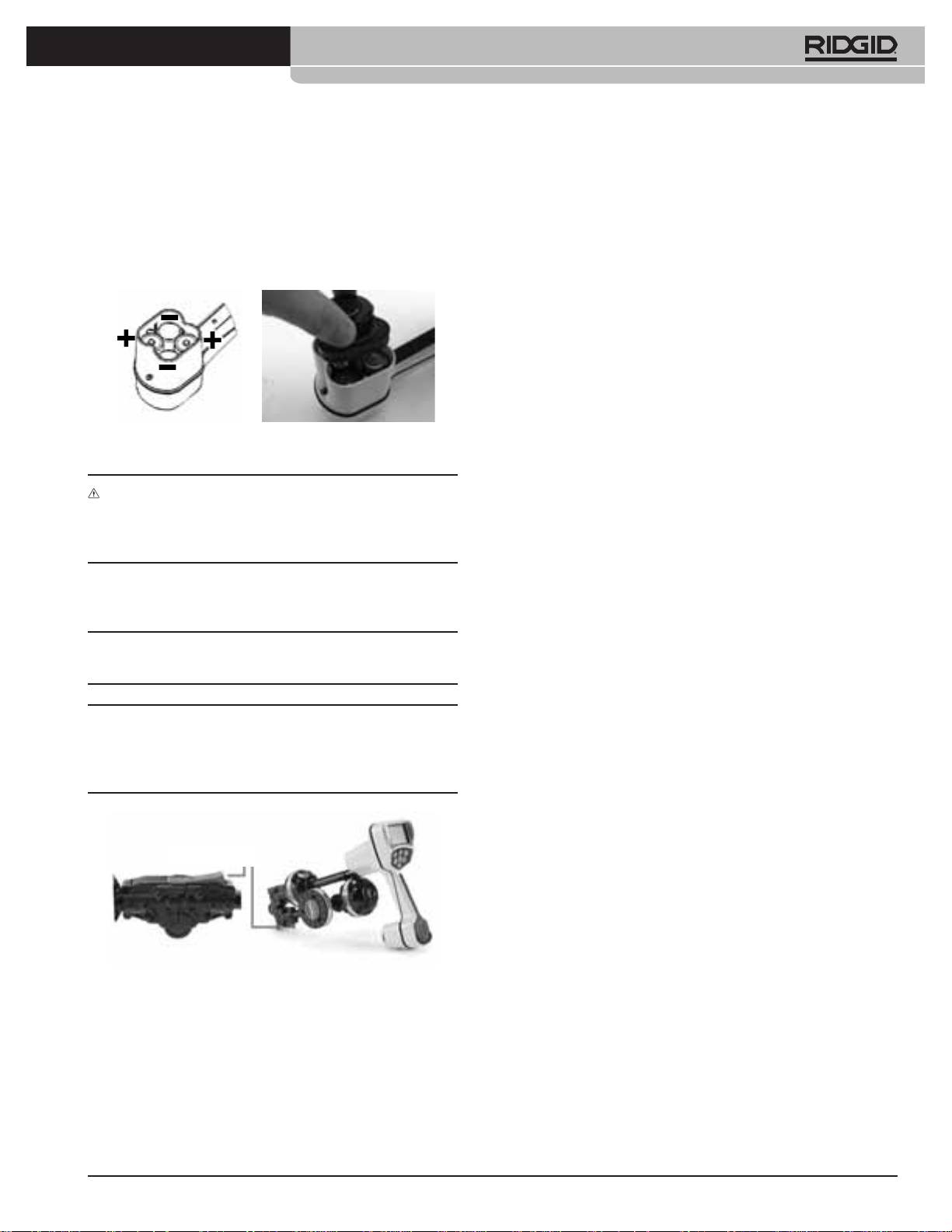
Installing/Changing Batteries
or cables.
2.
Passive Trace Mode, used for tracing electrical lines
that are already carrying 60 Hz current (U.S.), 50 Hz
current (Europe), or radio frequencies.
3.
Sonde Mode, used for locating Sondes in pipes,
conduits, or tunnels that are non-conductive or
cannot otherwise be traced.
Figure 2: Battery Case
CAUTION: Do not allow debris or moisture into battery
compartment. Debris or moisture may short the battery
contacts, leading to rapid discharge of the batteries, which
could result in electrolyte leakage or risk of re.
Folding Mast
IMPORTANT! Do not snap or whip the SR-20 mast to open or
close it. Open it and close it by hand only.
NOTE: Avoid dragging the lower antenna node on the
ground while locating with the SR-20. It may cause signal
noise which will interfere with results, and may eventually
damage the antenna.
Release Button
Figure 3: Folding Antenna Mast and Release Button
4
Ridge Tool Company
Tools For The Professional
TM
seekTech sR-20
Display Elements
The “basic features” of the SR-20 are on by default. Features
can be turned o or hidden to make the display clearer when
doing basic locating in uncomplicated situations.
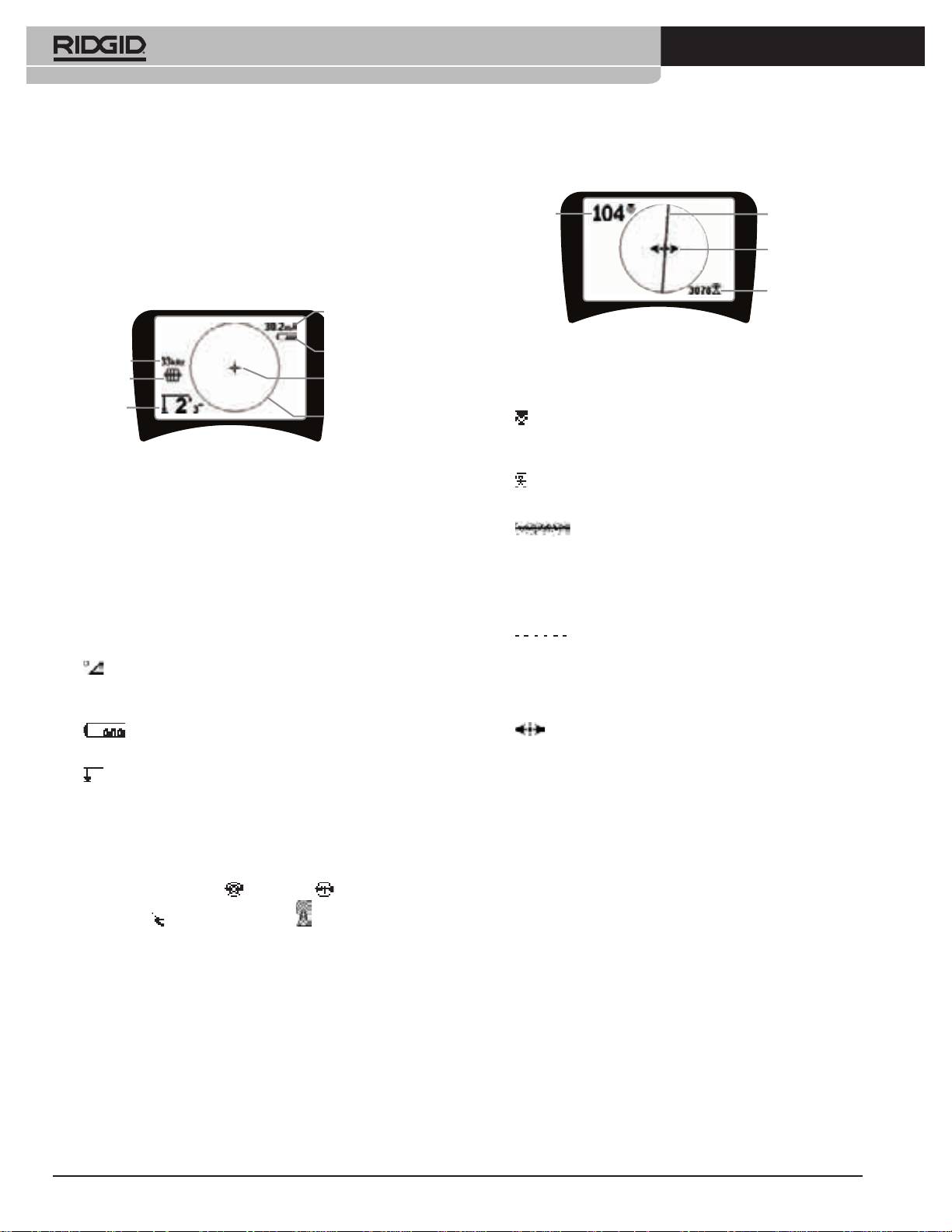
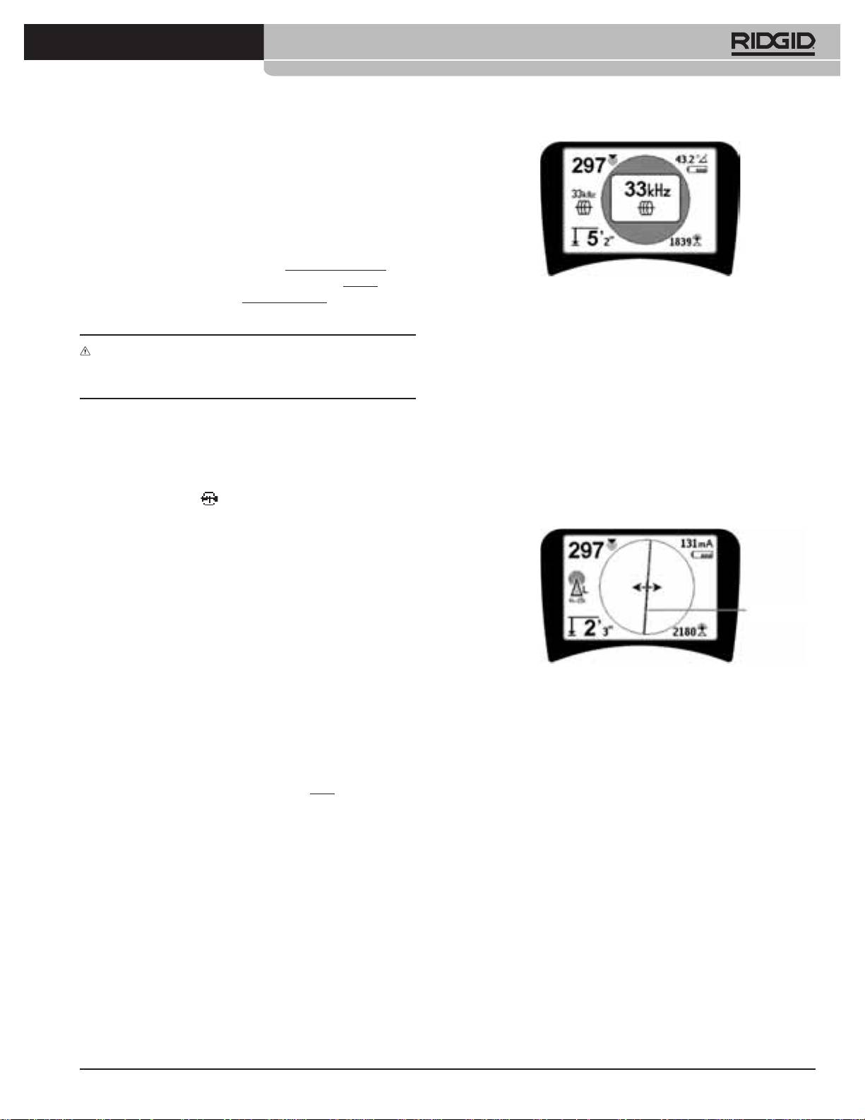
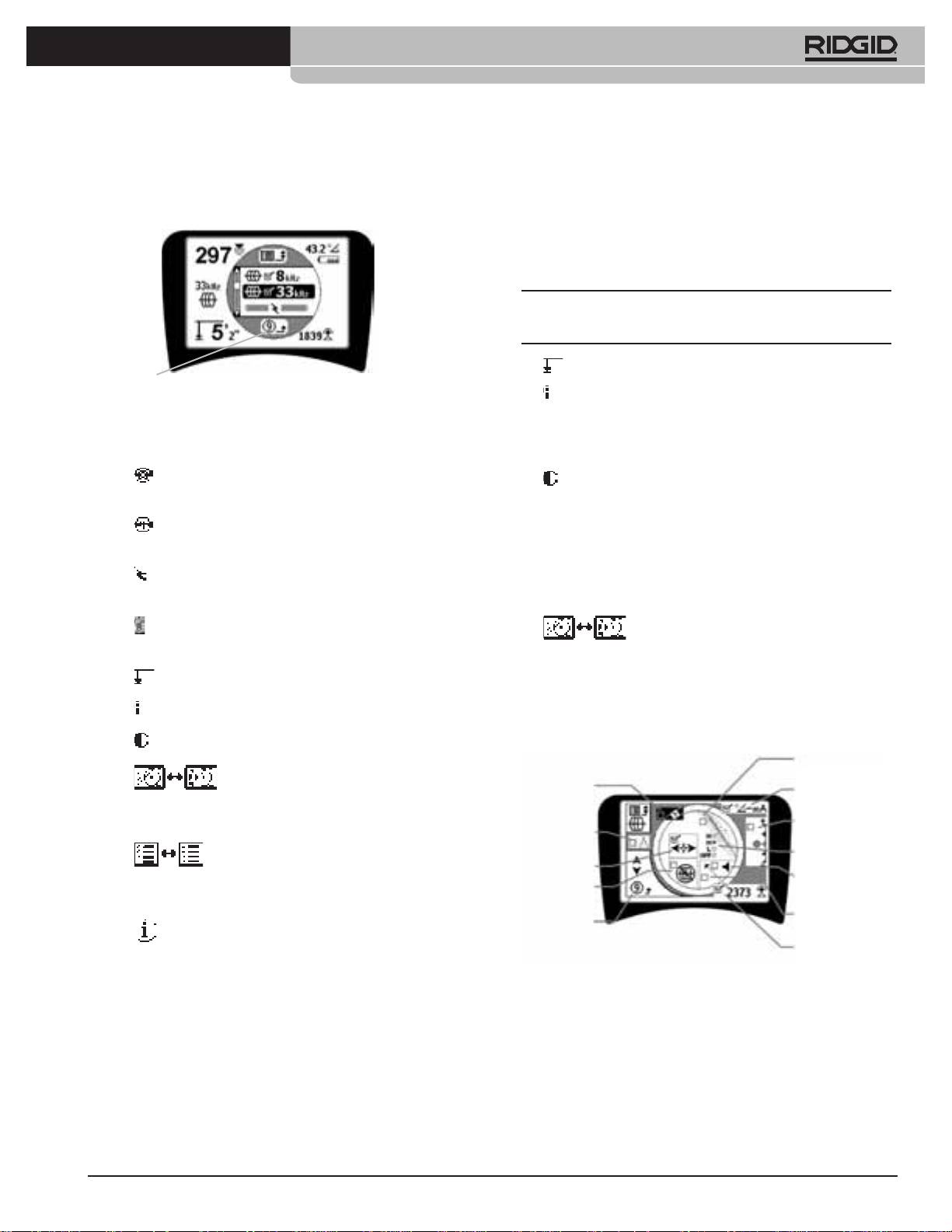
Common Display Elements
Current Strength/
Signal Angle
Battery Level
Frequency
Mode
Crosshairs
(Map Center)
Depth/
Distance
Active View Area
Display Elements: Active Line Trace Mode
Figure 4: Common Display Elements
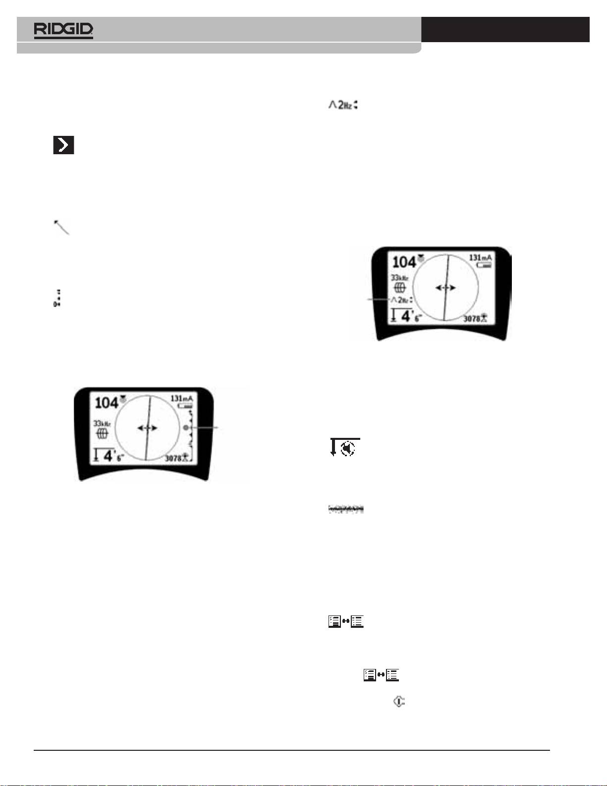
The display screen in Active Line Trace, Passive Line Trace or
Sonde mode will show the following features:
•
Active View Area – The area inside the circle on the
SR-20 display where the Tracing Line, Guidance Arrows,
and crosshairs are displayed.
•
mA Current Strength – Proportional to current on
the line. Switches to Signal Angle when Signal Angle is
greater than 35°.
•
Signal Angle – Field tilt from the horizontal; angle
toward the eld’s center; numeric value displayed in
degrees.
•
Battery Level – Indicates level of remaining
battery capacity.
•
Measured Depth/Distance – Displays the measured
depth when receiver is touching the ground directly over
signal source. Displays computed distance when the
antenna mast is pointed at a signal source in some other
manner. Displays feet/inches (U.S.A. default) or meters
(European default).
• Mode – Icon for Sonde
, Line Trace , Power (Passive
Line Trace)
, or Radio Frequency mode.
• Frequency – Shows current frequency setting in hertz or
kilohertz.
•
+ Crosshairs (Map Center) – shows operator’s position
relative to the target center.
Proximity
Tracing Line
Signal
Guidance Arrows
Signal Strength
Proximity
Tracing Line
Signal
Guidance Arrows
Signal Strength
Current Strength/
Signal Angle
Figure 5: Display Elements (Line Trace Mode)
Battery Level
Frequency
Mode
Crosshairs
In Active Line Trace Mode, the following features will also be
(Map Center)
displayed:
Depth/
Distance
Active View Area
•
Proximity Signal – Numerical indication showing how
close the signal source is to the locator. Displays from 1 to
999. (Line Trace modes only)
•
Signal Strength – Strength of signal as sensed by the
lower Omnidirectional antenna.
•
Tracing Line – The Tracing Line represents the
approximate axis of the detected eld. It represents detected
distortion in the eld by appearing less focused. (See page 22
for information on setting the sensitivity and how to enable
or disable the distortion response in the Tracing Line.)
•
Distortion Line – If the normal distortion
response of the Tracing Line is disabled, a second line is
shown, which represents the signal from the upper antenna
node. By comparing the two lines, the user can estimate the
degree of distortion present in a signal.
•
Guidance Arrows – The Guidance Arrows serve to
steer the operator toward the center of the detected eld, by
showing when the signals reaching the left and right.

Ridge Tool Company
5
Tools For The Professional
TM
seekTech sR-20
Display Elements: Passive Trace Mode
Default Frequencies
The screen elements in Passive Trace Mode are the same as
Currently available frequencies in default setting include:
those seen in Active Line Trace mode.
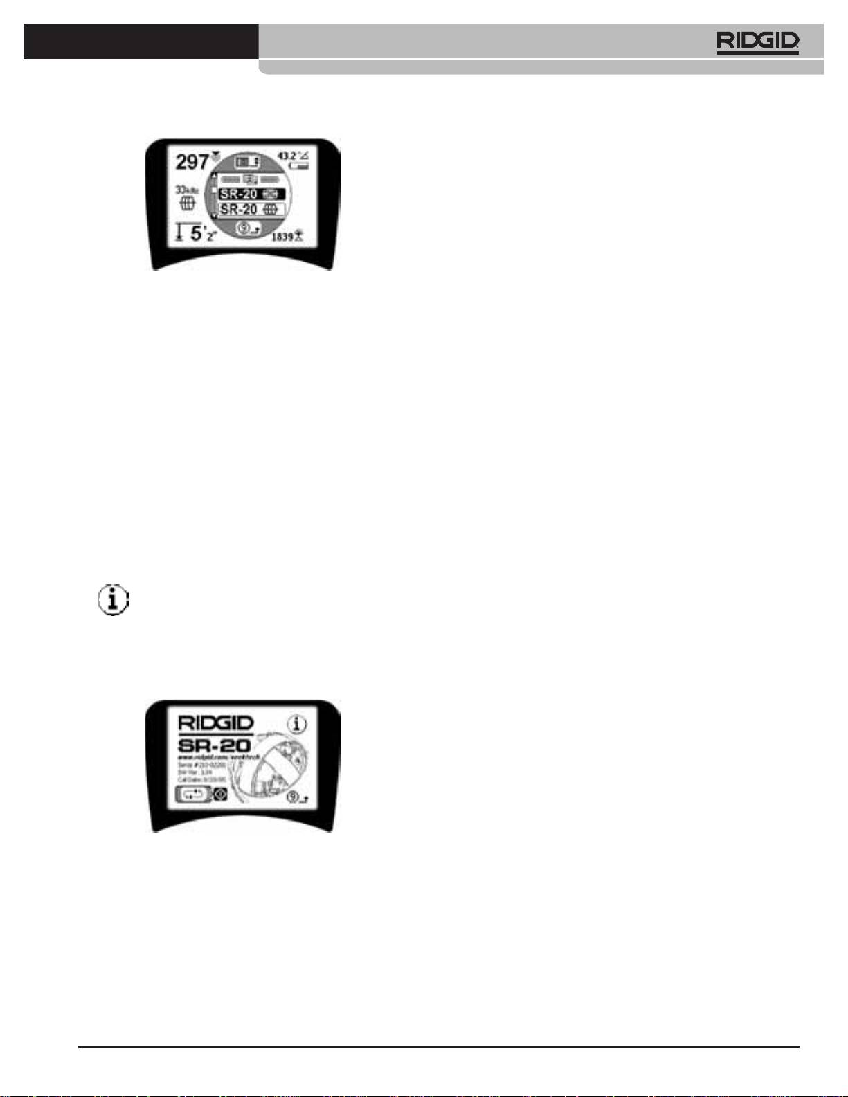
Display Elements: Sonde Mode
Sonde Mode
Pipe Direction
• 512 Hz
Signal
Strength
Pole Icon
Active Line Trace Mode:
Zoom Ring
• 128 Hz
Equator
• 1 kHz
Sonde Icon
• 8 kHz
• 33 kHz
Figure 6: Display Elements: Sonde Mode
Passive Line Trace Mode:
In Sonde mode, the screen elements include several features
th
• 50 Hz (9
)
that are unique to Sonde locating.
• < 4 kHz
•
| | Pipe Direction – Represents the approximate
direction of Sonde.
Radio Frequency
•
Sonde Icon – Appears when approaching the
• 4 kHz—15 kHz (L)
location of a Sonde.
• > 15 kHz (H)
•
Equator – Represents the mid-line of the Sonde’s
eld perpendicular to the axis of the Poles.
•
Pole Icon – Represents the location of either of the
two Poles of the Sonde’s dipole eld.
•
Zoom Ring – Appears when the locator moves
close to a Pole.
The use of these features is described in the Active Line
Tracing, Passive Line Tracing, and Sonde Locating sections.
6
Ridge Tool Company
Tools For The Professional
TM
seekTech sR-20
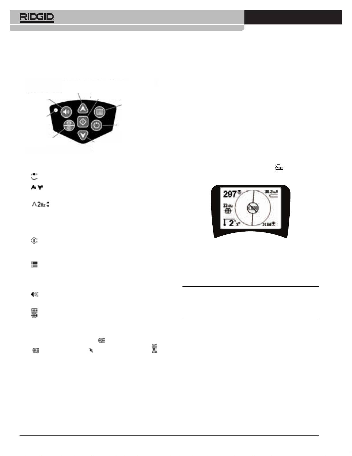
Keypad
Operation Time
Using alkaline cells, typical operation time is from about 12
Up Key
Menu Navigation/Signal Focus/
to 24 hours depending on sound volume and how often the
Proximity Threshold Control
backlight is on. Other factors that aect the operation time
Select Key
will include chemistry of the battery (many of the new high
Volume Controle Key
Audio Tone Reset/Menu Item Select
performance batteries, such as the “Duracell® ULTRA” last
Menu Key
10%-20% longer than conventional alkaline cells under high
demand applications). Operation at lower temperatures will
also reduce battery life.
Light Sensor
Power ON/
OFF Key
To preserve battery life, the SR-20 will automatically shut
down after 1 hour of no key presses. Simply power the unit
Frequency Key
on to resume use.
Down Key
Menu Navigation/Signal Focus/
Proximity Threshold Control
Low Battery Warning
Figure 7: Keypad
When the battery gets low, a battery icon will periodically
appear in the map area on the screen.
• Power On/O Key – Powers SR-20 on.
•
Up and Down Keys – Used for locating choices during
menu selection.
• Signal Focus – If activated, the Up and Down Keys
will change the Signal Focus setting up and down. A long
press (greater than ½ second) on these keys will adjust
the Proximity Threshold, while a quick press will adjust
the Signal Focus.
•
Select Key – Used to make a choice during Menu
Figure 8: Low-Battery Warning
selection; in normal operation, to force a Measured Depth
reading and recenter audio tone.
Just before complete shut down there will be a
non-interruptible power down sequence. An extended buzz
•
Menu Key – Used to display a “tree” of choices including
frequency selections, display element choices, brightness
will sound when the SR-20 is about to go into shutdown
and contrast, and restoring default settings. In a menu, will
sequence.
move up one level.
NOTE: Voltage on rechargeable batteries may sometimes
•
Volume Control Key – Used to raise or lower the volume
drop so quickly that the unit will just shut down. The unit
setting.
will power down and restart. Just replace the batteries and
power the unit back on.
•
Frequency Key – Used to set the In-Use Frequency of the
SR-20 from the set of Checked-Active frequencies. The list of
frequencies that have been set to Checked-Active status can
be modied via the Menu Key. Frequencies are grouped into
four sets: Sonde Frequencies (
), Line Trace Frequencies
(
), Power Frequencies ( ) and Radio Frequencies ( ).
Each press cycles to the next Checked-Active frequency.
•
Light Sensor – In Automatic mode, the light sensor controls
when the backlight goes on or o depending on ambient
light.
Ridge Tool Company
7
Tools For The Professional
TM
seekTech sR-20
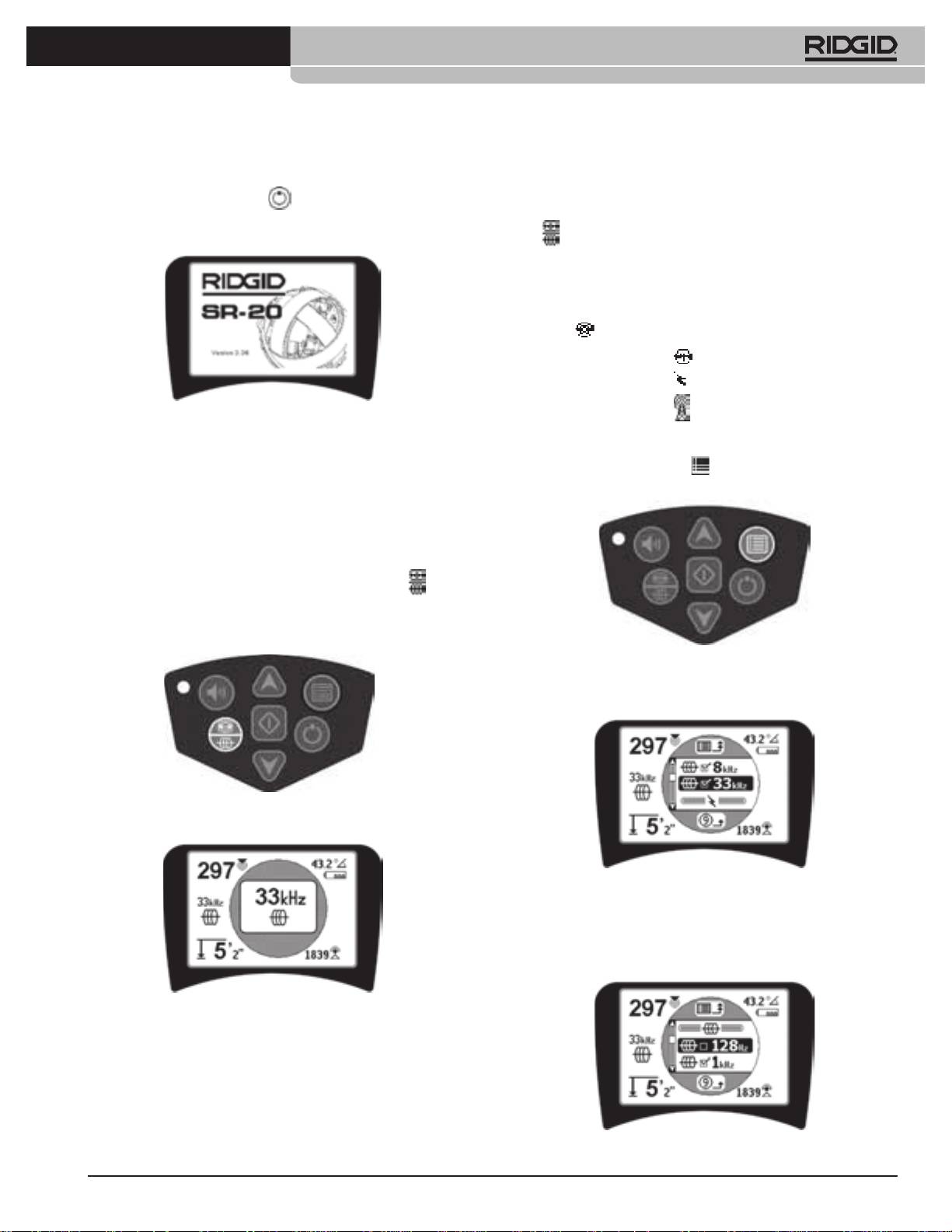
Starting Up
Activating Frequencies
Frequencies can be chosen for the set of Checked-Active
After pressing the Power Key
on the keypad, the RIDGID
frequencies so they will be available using the Frequency
logo displays, and the software version number will appear
on the left of the screen.
Key
.
Each frequency is activated by choosing it from a list in the
Main Menu (See Figure 13). Frequencies are grouped by
category:
S
onde
Active Line Trace
Passive Line Trace
Figure 9: Start-up Screen
Radio
Set Up
1. Push the Menu Key
:
Once the SR-20 is up and running the next step is to set up
the frequencies needed that match the transmitter or line to
be located.
Checked-Active frequencies are already selected for use and
appear in sequence by pressing the Frequency Key . (For
example, the line trace frequency of 33 kHz is available by
pressing the Frequency Key.)
Figure 12: Menu Key
The Main Menu screen is then activated:
Figure 10: Frequency Key
Figure 13: Main Menu
2. Using the Up and Down Keys, highlight the
frequency desired (Figure 14). In this example, the
operator is activating a 128 Hz frequency.
Figure 11: Line Trace Frequency
Selected with Frequency Key
Figure 14: Highlighting a Desired Frequency (128 Hz)

8
Ridge Tool Company
Tools For The Professional
TM
seekTech sR-20
Sounds of the SR-20
3. Press the Select Key
(shown below) to check the
box for each frequency to be used.
The sound level is driven by the proximity to the target. The
closer to the target, the higher the sound pitch will be. A
rising tone indicates increasing signal.
In Active Line Trace or Passive Line Trace mode, sound is on
one continuous curve and does not rescale.
When there is no distortion present, the sound of the SR-20 is
a clear warbling sound when on the left side of the detected
eld, with a slight click added when on the right side of the
detected eld. If distortion is detected a sound similar to
AM radio static sound can be heard, which gets stronger as
Figure 15: Select Key
the degree of distortion increases. If the distortion response
feature is disabled, the static sound does not occur.
In Sonde Mode, the pitch will “ratchet” upward. That is, it will
rise and then rescale (fall) in pitch while approaching the
Sonde. Moving away from the Sonde, it will drop to a lower
pitch and remain there as long as one moves away from the
Sonde.
If desired, force the sound to recenter at a medium level (in
any mode) by pressing the Select Key during operation.
Figure 16: Desired Frequency Checked
Key Items in Using the SR-20
4. Frequencies that have been selected for use will show
SIGNAL STRENGTH represents the strength of the eld being
a check in the box next to them.
detected by the lower antenna node of the SR-20, converted
mathematically for scalability. In a clear and undistorted eld,
5.
Press the Menu Key
again to accept the choice
you can locate based on Signal Strength alone.
and exit.
PROXIMITY SIGNAL reects the proximity of the locator to
the target utility; the closer the locator moves to the center
of the detected eld, the higher the Proximity Signal number
gets. The Proximity Signal is calculated from the ratio of the
signals received at the lower and upper antennas, adjusted
for scalability.
DISTORTION is the degree to which the eld detected is
deformed from the simple circular shape of an ideal magnetic
eld caused by current in a long conductor. If multiple elds
are present, the detected eld is pushed or pulled out of
Figure 17: Menu Key
shape and the dierent antennas will pick up dierent eld
strengths. Distortion is reected by the Tracing Line growing
The Main Menu lists all frequencies available for activation.
unfocused instead of sharp on the display screen.
For information on adding additional frequencies to the Main
Menu so they can be chosen for activation, see “Frequencies
GUIDANCE ARROWS are driven by the signals received at the
Selection Control” on page 22.
side-wheel antennas of the SR-20. When the elds detected
by these side antennas are equal, the arrows will center. If
one is receiving a stronger eld signal than the other, the
arrows will point toward the probable center of the target
conductor.
Ridge Tool Company
9
Tools For The Professional
TM
seekTech sR-20
Line Tracing with the SR-20
Active Line Tracing
In active line tracing, underground lines are energized with a
Line Transmitter.
Line transmitters energize lines by direct connection with
clips, by directly inducing the signal using a clamp, or by
inducing the signal using inductive coils built into the
Figure 18: Line Trace Frequency Chosen
transmitter.
with the Frequency Key
(This screen will ash briey when a
WARNING: Connect the ground lead and the power lead
new frequency is chosen)
of the transmitter before powering the transmitter on, to
2.
Observe the Proximity Signal to ensure that the
avoid electric shock.
receiver is picking up the transmitted signal. The
Proximity Signal should peak over the line and drop
1.
Energize the target conductor according to the
o on either side.
transmitter manufacturer’s instructions. Select the
transmitter frequency. Set the frequency used on the
3.
When tracing, the direction the pipe or cable is
SR-20 to the same frequency used on the transmitter
running will be shown on the screen by the Tracing
using the Frequency Key. Be sure the frequency has a
Line. The Tracing Line will be a clear, single line if the
line trace icon
.
eld being detected is undistorted.
Direct Connect Method: The transmitter is attached by
direct metal-to-metal connection to the target conductor at
some access point such as a valve, a meter, or other point.
Important: The connection between the transmitter and the
conductor must be a clean, rm connection. The transmitter
is also connected to a ground stake providing a strong open
Tracing Line
path to ground. Important: A weak ground connection is
the most frequent cause of a poor tracing circuit. Make sure
the transmitter is well connected to ground, and has enough
exposure to the ground to allow current to ow through the
Figure 19: Tracing Line Showing Low Distortion
circuit.
Inductive Clamp Mode: The transmitter is connected to an
4. If other elds are interfering in some way, the
inductive clamp which is then closed around a pipe or cable.
distortion caused by those elds will be reected by
The transmitter energizes the clamp, which then induces a
a blurring of the Tracing Line. This alerts the operator
current in the conductor.
that the apparent axis of the line may be inuenced
by other elds, and requires careful evaluation. The
Inductive Mode: The transmitter is placed over the conductor,
more distorted the detected eld, the broader the
at right angles to it. There is no direct connection; the internal
cloud around the Tracing Line will be.
coils of the transmitter generate a strong eld through
the ground which induces a current in the underground
The Tracing Line has three important functions.
conductor of interest. Important: If the transmitter is too
It represents the location, and the direction, of the
close to the SR-20 in this mode, it can cause “air-coupling”
signal being traced. It reects changes in direction
which means the locator is reading on the transmitter’s eld,
of the target utility — when the utility makes a turn,
not on the target conductor.
for example. And it helps recognize signal distortion.
It does this by becoming cloudier as distortion
increases.
10
Ridge Tool Company
Tools For The Professional
TM
seekTech sR-20
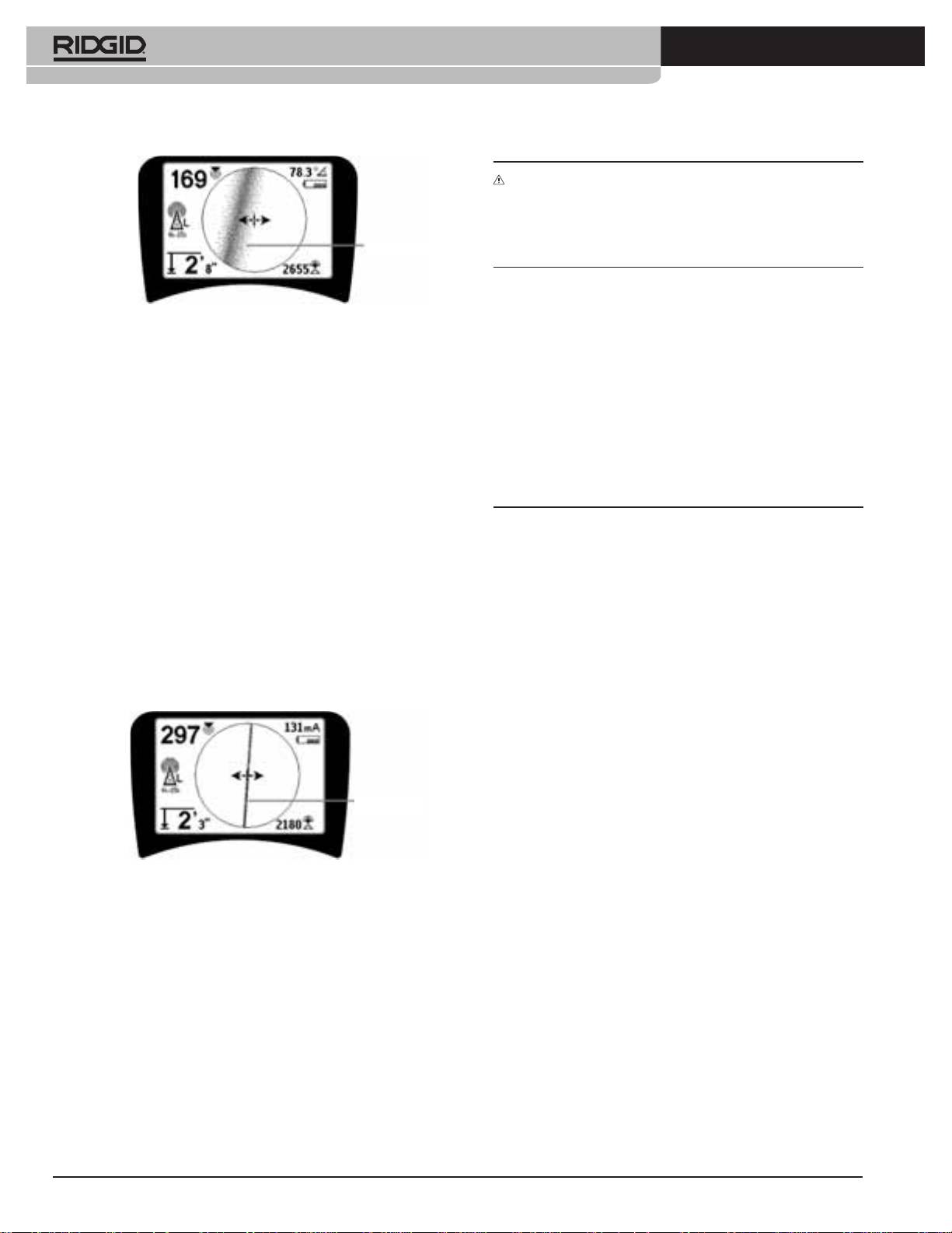
WARNING: Care should be taken to watch for signal
interference that may give inaccurate readings. The
Tracing Line is only representative of the position of the
buried utility if the eld is UNDISTORTED. Do NOT base a
Tracing Line
locate solely on the Tracing Line.
Always cross check the locate by ensuring that:
•
The Tracing Line shows little or no distortion response
Figure 20: Tracing Line Showing High Distortion
(blurriness).
•
The Proximity Signal and the Signal strength maximize
Use the Guidance Arrows, Proximity Number, Signal
when the Tracing Line crosses the map center.
Strength, and Tracing Line to guide the line trace. These
pieces of information are generated from discrete signal
•
The Measured Depth increases appropriately as the
characteristics to help the operator understand the quality
unit is raised vertically and the Tracing Line remains
of the locate. An undistorted signal emitted from a line is
aligned.
strongest directly over that line. (Note: Unlike the Signal
Measured Depth readings should be taken as estimates
Trace lines, the guidance arrows require that the user orient
and actual depths should be independently veried by
the locator so that the guidance arrows point 90 degrees to
potholing or other means prior to digging.
the Signal Trace line. (See Figure 21).
5.
Note that an undistorted line will also be clear
As always, the only way to be certain of the location of a
rather than blurred on the screen, and the sound
utility is through visual conrmation by exposing the utility.
accompanying the image will have no “static” in it.
The accuracy of position and depth measurement improves
as the SR-20 lower antenna node is placed closer and closer
6.
Condence in the accuracy of a locate can be
to the target utility. Rechecking the Measured Depth and
increased by maximizing the Proximity Signal (and/
position periodically during the excavation process can help
or Signal Strength), balancing the Guidance Arrows
avoid damage to a target utility and may identify additional
and centering the Tracing line on the screen. Conrm
utility signals that were not noticed prior to excavation.
a locate by testing whether the Measured Depth
reading is stable and reasonable. (See page 12.)
When line tracing, it is important to remember that tees,
curves, other conductors in the vicinity, and nearby masses of
metal can add distortion to the eld, requiring closer scrutiny
of the data to determine the true path of the target utility.
See below for tips on improving the signal.
Circling the last location of a clear signal at a distance of
Tracing Line
about 20 feet (6.5 m) can clarify if the distortion is coming
from a local turn or tee in the line, and enable the operator to
again pick up the line nearby.
If the signal is clear, the SR-20 will often show a straight
Figure 21: High Probability Locate
signal line with very little distortion right up to a 90-degree
tee, show a small amount of distortion as it follows around
the curve, and then show a clear signal again as it resumes
its travel after the tee. It shows very clearly when the line is
turning.
Ridge Tool Company
11
Tools For The Professional
TM
seekTech sR-20
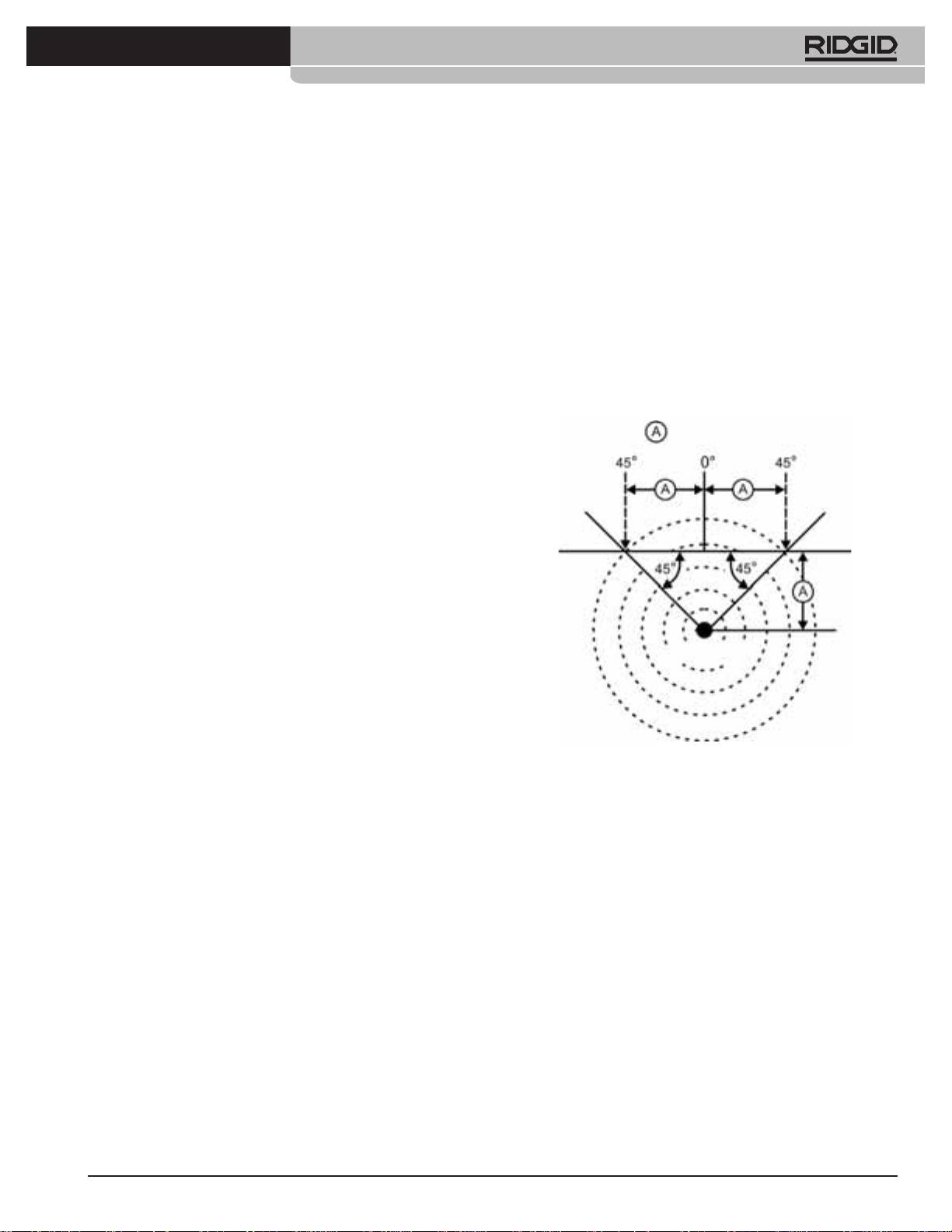
Operating Tips for Active Line Tracing
M
ove the SR-20 perpendicularly to both sides of the
traced line until the numeric Signal Angle indicator reads
• The SR-20 quickly identies distorted elds. If the
45
degrees. Be sure to keep the lower Omnidirectional
guidance arrows are centered on the screen, and the
antenna node at the same height, and the locator
Trace Line is not centered (or if the Proximity Signal
mast vertical. If there is little or no distortion the traced
number and Signal Strength are not maximized), then
line should be in the middle and the distance to each
distortion is creating a complex non-circular eld.
45
degree point should be approximately the same on
either side. If the signal is undistorted, then the distance
•
To improve the tracing circuit:
from the line center to the 45° point is approximately
a) Try changing the frequency used to a lower one.
equal to the depth.
b) Move the ground stake position away from the line
A
nother variation of this technique is to move the same
to be traced. Use a larger ground contact surface
distance to the right and left of the traced line, say
(e.g., a shovel blade).
24
inches (60 cm) and check that the Signal Strength
c)
Make sure that the line is not commonly bonded to
readings are similar.
another utility. (Undo common bonds only if safe to
= Same distance
do so).
d)
Move the transmitter to a dierent point on the line,
if possible.
•
If the Tracing Line will not center or if it moves across
the screen erratically, then the SR-20 may not be
receiving a clear signal. The Measured Depth and the
Proximity Signal may also be unstable under these
circumstances.
Ground
a)
Check the transmitter to be sure that it is operating
and well grounded. Good connection and good
grounding overcome low current problems.
b
) Test the circuit by pointing the lower antenna at
Energized Pipe
either transmitter lead.
c)
Check that the SR-20 and transmitter are operating
on the same frequency.
d)
Try dierent frequencies, starting with the lowest,
until the line can be picked up dependably. Using
Figure 22: Checking for Distortion
lower frequencies can overcome bleed over
problems.
• While tracing, the Proximity Signal and Signal Strength
e)
Relocate the ground connection for a better circuit.
should maximize, and the Measured Depth minimize, at
Ensure there is enough contact (ground stake is
the same place where the guidance arrows center on the
suciently deep) especially in dryer soils.
display. If this is not the case, the utility may be changing
f
) In extremely dry soil, wetting the area around the
direction or other coupled signals may be present.
ground stake will improve the circuit. Be aware the
•
Higher frequencies bleed over to adjacent utilities more
moisture will dissipate and evaporate, reducing the
readily, but may be needed to overcome breaks in
quality of the circuit over time.
tracer wires or go over insulating couplers. If the line is
•
Using the numeric Signal Angle Indicator is another
ungrounded at the far end, higher frequencies may be
way to check for distorted signals.
the only means to make the line traceable.
•
When using the transmitter inductively, be sure to begin
the locate about 30 feet (10 m) away to avoid “direct
coupling” (also know as air coupling).
12
Ridge Tool Company
Tools For The Professional
TM
seekTech sR-20
• While tracing, the mapping display operates best under
Current and Signal Angle Reading
the following conditions:
The Current Strength (mA) and Signal Angle indicator
1.
The line is level
( ) in the upper right corner of the screen will display the
current detected on the traced line, in milliamps, when the
2. The SR-20 Locator is above the target utility elevation
computed angle to the center of the detected eld is less
3. The SR-20 antenna mast is held approximately
than 35° and the SR-20 crosses the center of the eld as
vertical
sensed by the guidance arrows.
When moving across the center of the eld the current display
If these conditions are not met, pay close attention to
will “latch” the displayed current value (retain it in the display)
maximizing Signal Strength.
until the guidance arrows reverse again, at which point the
In general, if the SR-20 is used in a zone over the target
latched display will be updated. The update and latch cycle
line within a sweep area of about two “depths” of the line,
occurs whenever the guidance arrows reverse.
the map will be useful and accurate. Be aware of this when
When the angle to the center exceeds 35°, the Signal Angle
using the map if the target or line is very shallow. The width
indicator will again replace the Current indicator, and the
of the useful search area for the map can be small if the line
display will show the computed angle to the center of the
is extremely shallow.
detected eld.
Measuring Depth (Line Tracing Modes)
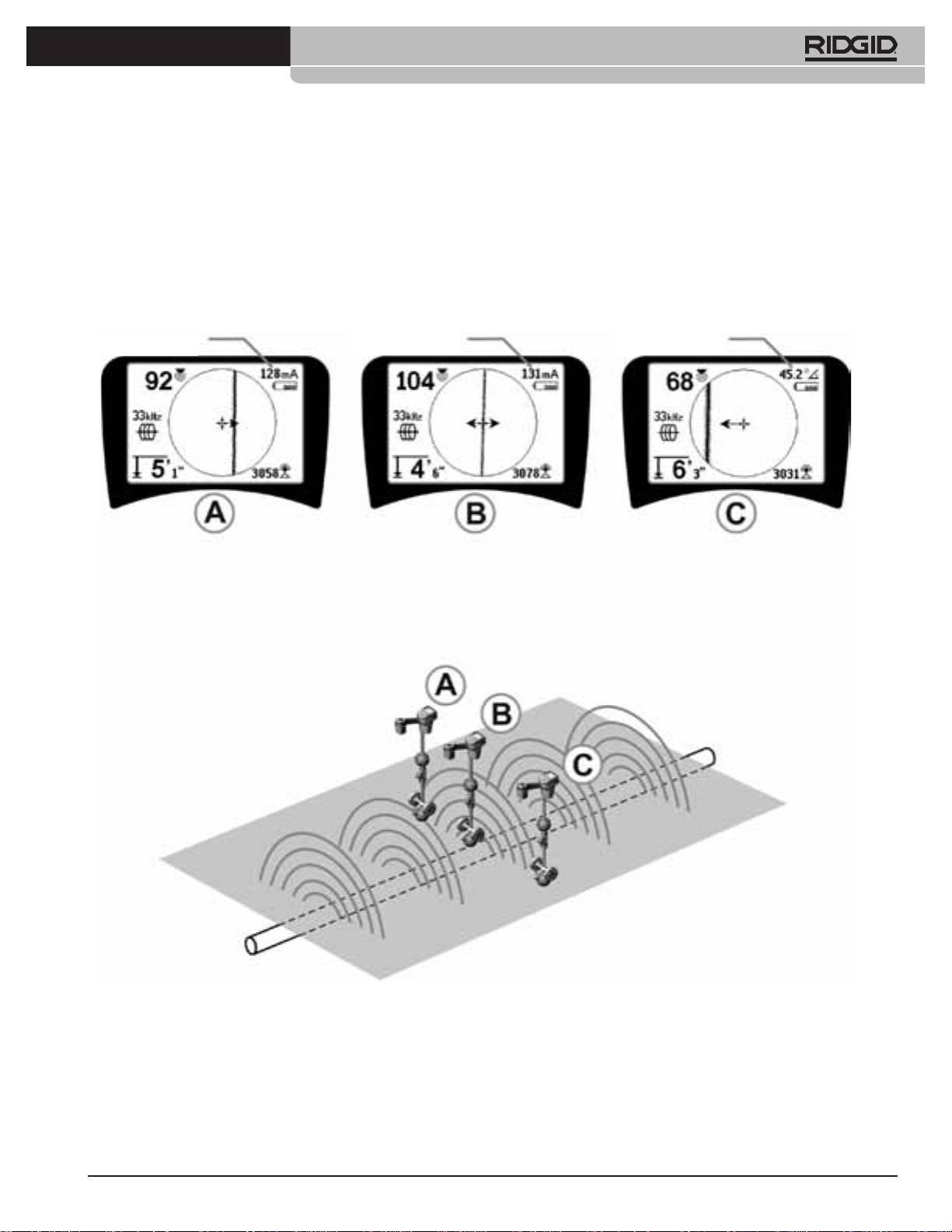
Clipping (Tracing Modes)
The SR-20 calculates Measured Depth by comparing the
Occasionally the Signal Strength will be strong enough that
strength of the signal at the lower antenna to that at the
the receiver will be unable to process the whole signal, a
upper antenna.
condition known as “clipping”. When this occurs, a warning
Measured Depth is measured correctly in an undistorted eld
symbol
will appear on the screen. It means that the
when the bottom antenna is touching the ground directly
signal is particularly strong. If clipping persists, remedy it
above the signal source and the antenna mast is vertical.
by increasing the distance between the antennas and the
1.
To measure depth, place the locator on the ground,
target line OR by reducing the strength of the current from
directly above the Sonde or the line.
the transmitter.
2.
Measured Depth will be shown in the lower left hand
NOTE: Measured Depth Display is disabled under clipping
corner.
conditions.
3.
A Measured Depth reading can be forced by pressing
the Select Key.
4.
Measured Depth will be accurate only if the signal is
undistorted and the antenna mast is held vertical.
Testing for the consistency of the Measured Depth reading
can be done by raising the SR-20 a known distance (say,
12 inches (33 cm)) and observing whether the Measured
Depth indicator increases by the same amount. Small variation
is acceptable, but if the Measured Depth does not change, or
changes drastically, it is an indication of a “distorted” eld, or
very low current on the line.
NOTE: In Active Line Trace or Passive Line Trace modes,
pressing and holding the Select Key will force a Measured
Depth reading and will force the Signal Angle indicator to
change to Current. If sound is set on, it will also recenter the
audio tone.
Ridge Tool Company
13
Tools For The Professional
TM
seekTech sR-20
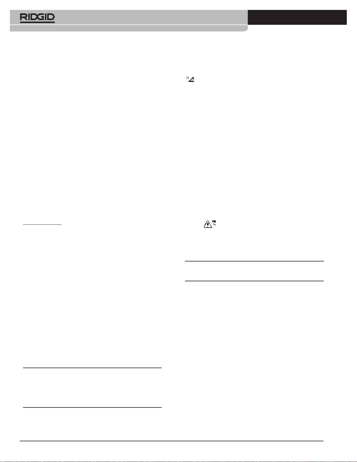
Current Strength
Current Strength Signal Angle
Figure 23: Screen Display in Dierent Locations (Line Tracing)
14
Ridge Tool Company
Tools For The Professional
TM
seekTech sR-20
Passive Line Tracing
The 9x multiple is the setting most commonly used to
locate 50/60 Hz signal. In well-balanced high voltage
In passive mode, the SR-20 is looking for electromagnetic
electric distribution systems, the 5x multiple may work
“noise” that has found its way onto a buried utility line by any
better. The 100 Hz (in 50 Hz countries) and 120 Hz (in
available means.
60
Hz countries) frequency settings are particularly
useful for pipelines that have been equipped with
Electromagnetic signals can get onto buried utility lines in a
cathodic protection using rectiers.
variety of ways.
As in Active Line Tracing, the Tracing Line will reect distortion
The most common reason is by means of direct connection
in the detected eld by appearing unfocused or cloudy in
to some signal source. All operating electronic devices that
proportion to the distortion. This “distortion response” is
are connected to AC power will radiate a certain amount
useful in recognizing when the eld being traced is being
of electronic “noise” back onto the power lines they are
distorted by other elds of metallic objects in the vicinity.
connected to.
3.
There are also two additional radio frequency
In some areas for example, buried utilities act as antennas for
high powered, low frequency radio transmissions (submarine
bands
to help locate lines passively. They are:
navigational and communication signals in the UK for
example) and will reradiate these signals. These reradiated
• 4kHz to 15kHz (LF)
signals can be very useful for locating.
• > 15kHz (HF)
In short, frequencies can show up on buried conductors in
The Radio Frequency and <4 kHz bands can be useful in
numerous ways, and these can be picked up passively, if the
discriminating when tracing in a noisy environment. They
elds are strong enough.
are also very helpful in nding lines on blind searches.
When searching over a wide area where the location of
1.
Select a Passive Line Trace Frequency (
or icon).
targets is unknown, one useful approach is to have multiple
frequencies selected for use and to check the area at a
number of frequencies in sequence looking for meaningful
signals.
In general, directly connected Active Line Tracing is more
reliable than Passive Line Tracing.
WARNING: In Passive Line tracing, or when signals are
extremely weak, the Measured Depth will generally read too
DEEP and the actual buried depth may be MUCH shallower.
9th
Figure 24: 60
Hz Passive Trace Frequency
2. The SR-20 has multiple Passive Line Trace
frequency settings. Power frequencies (identied
with the power icon
) are used to locate signals
generated as the result of power transmissions,
usually 50 or 60 Hz. To reduce the eects of inherent
noise from line-load or neighboring devices the SR-20
can be set to locate various multiples (or harmonics)
of the base 50/60 Hz frequency up to 4,000 Hz.
Ridge Tool Company
15
Tools For The Professional
TM
seekTech sR-20
Operating Tips for Passive Line Tracing
Sonde Locating
1. In Passive Locating if you are looking for a known line,
The SR-20 can be used to locate the signal of a Sonde
be sure you are using the best frequency for the line
(transmitter).
in question. This may be, for example, be 50 Hz (1) for
a power line, or it may turn out that 50 Hz (9) produces
IMPORTANT! Signal strength is the key factor in determining
a more reliable response on a particular line.
the Sonde’s location. Take care to maximize the Signal
Strength prior to marking an area for excavation.
2.
If seeking a cathode-protected pipe in Passive Mode,
The following assumes that the Sonde is in a horizontal pipe,
use higher-frequency (greater than 4 kHz) to pick up
the ground is approximately level and the SR-20 is held with
harmonics.
the antenna mast vertical.
3.
Remember that pipes can carry currents that will
show up on a Passive Trace as well as cables will; the
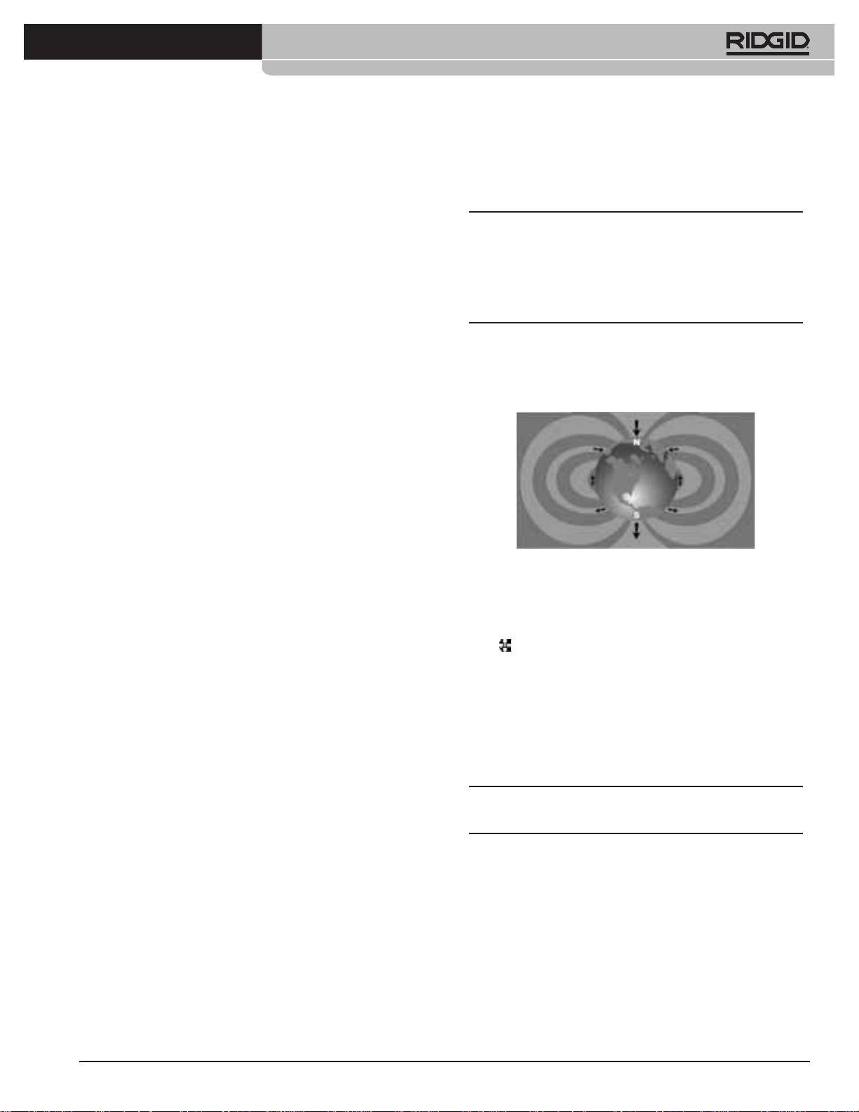
The eld of a Sonde is dierent in form from the circular eld
only guarantee of a locate is inspection.
around a long conductor such as a pipe or cable. It is a dipole
eld like the eld around the Earth, with a north Pole and a
4.
In general, Passive Trace locating is less reliable than
south Pole.
Active Line Tracing because Active Line Tracing oers
the positive identication of the signal from the
transmitter.
5.
Especially in Passive Line Tracing, knowing that you
have found something is not the same as knowing
what you have found. It is essential to use all the
indicators available, such as Measured Depth, Signal
Strength, etc., to conrm a locate. If it is possible to
nd part of a passively-located cable, it can then be
energized using a transmitter and positively traced.
Figure 25: Earth’s Dipole Field
6.
While Passive Line Trace is most often used on
In the Sonde’s eld, the SR-20 will detect the points at either
50/60 Hz power lines, other cables such as phone
end where the eld lines curve down toward the vertical,
lines, CATV lines, etc., can be energized by transient
and it will mark these points on the map display with a “Pole”
radio frequencies in the region and may appear on
icon (
). The SR-20 will also show a line at 90 degrees to the
Passive Line Trace searches.
Sonde, centered between the Poles, known as the “Equator”,
much like the Equator on a map of the Earth if the planet
were viewed sideways (See Figure 25).
Note that because of the SR-20’s Omnidirectional antennas,
the signal stays stable regardless of orientation. This means
the signal will increase smoothly when approaching the
Sonde, and decrease smoothly moving away.
NOTE: A Pole is found where eld lines turn vertical. The
Equator occurs when the eld lines are horizontal.

16
Ridge Tool Company
Tools For The Professional
TM
seekTech sR-20
Location Methods
Pole
Pole
There are three major parts to locating a Sonde. The
rst step is to localize the sonde. The second part is
Equator
pinpointing. The third is verifying its location.
Step 1: Localize the sonde
• Hold the SR-20 so the antenna mast is pointing
outward. Sweep the antenna and listen to the sound,
it will be highest when the antenna mast is pointing
in the direction of the Sonde.
Figure 26: Dipole Field
• Lower the SR-20 to its normal operating position
(antenna mast vertical) and walk in the direction of the
When locating a Sonde, rst set up the locate:
Sonde. Approaching the Sonde, the Signal Strength
•
Activate the Sonde before putting it in the line. Select
will increase and the audio tone will rise in pitch. Use
the same Sonde frequency on the SR-20 and make
the Signal Strength and the sound to maximize the
sure it is receiving the signal.
signal.
After the Sonde has been sent into the pipe, go to the
•
Maximize the Signal Strength. When it appears to
suspected Sonde location. If the direction of the pipe is
be at its highest point, place the SR-20 close to the
unknown, push the Sonde a shorter distance into the line
ground over the high signal point. Be careful to hold
(~15 feet (5 m) from the access is a good starting point).
the receiver at a constant height above the ground as
distance aects Signal Strength.
•
Note the Signal Strength and move away from the
high point in all directions to verify that the Signal
Strength drops signicantly on all sides. Mark the
point with a yellow Sonde Marker.
Figure 27: Poles and Equator of a Sonde
If while “getting closer” the Equator appears on the screen,
follow it in the direction of an increasing Signal Strength to
localize the Sonde.
Ridge Tool Company
17
Tools For The Professional
TM
seekTech sR-20
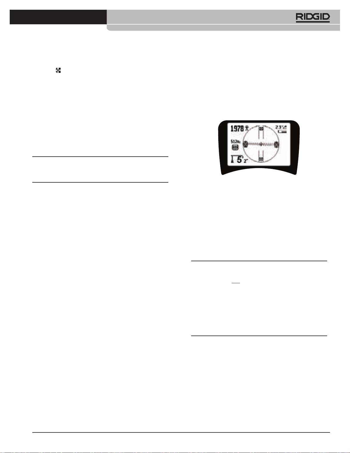
Step 2: Pinpoint the Sonde
Step 3: Verify the locate
The Poles should appear on either side of the maximum
• It is important to verify the Sonde’s location by
signal point, an equal distance on either side if the Sonde
crosschecking the receiver’s information and
is level. If they are not visible on the screen at the point of
maximizing Signal Strength. Move the SR-20 away
maximum Signal Strength, move from the maximum point
from the maximum Signal Strength, to make sure that
perpendicular to the dotted line (Equator) until one appears.
the signal drops o on all sides. Make sure to move
Center the locator over the Pole.
the unit far enough to see a signicant signal drop in
each direction.
Where the Poles occur depends on the Sonde’s depth. The
deeper the Sonde, the further away from it the Poles will be.
The dotted line represents the Equator of the Sonde. If the
Sonde is not tilted, the Equator will intersect the Sonde
at maximum Signal Strength and minimum Measured
Depth.
NOTE: being on the Equator does not mean that the locator
is over the Sonde. Always verify the locate by maximizing
Signal Strength and marking both Poles.
Figure 28: Sonde Locate: Equator
•
Mark the rst Pole location found with a red triangular
• Double check the two Pole locations.
Pole marker. After centering on the Pole, a double
line indicator represents how the Sonde is lying
• Notice that the Measured Depth reading at the
underground, and in most cases also represents the
maximum Signal Strength location is reasonable and
pipe’s approximate direction.
consistent. If it seems far too deep or too shallow,
recheck that there is an actual maximum Signal
•
When the locator gets close to a Pole, a zoom ring will
Strength at that location.
appear centered on the Pole.
•
Notice that the poles and the point of highest Signal
•
The second Pole will be a similar distance from the
Strength lie on a straight line.
Sonde location in the opposite direction. Locate it in
the same manner and mark it with a red triangular
marker.
IMPORTANT! Remember that being on the Equator does
not mean one is over the Sonde. Seeing two Poles aligned
•
If the Sonde is level, the three markers should be
on the display is not a substitute for centering over each
aligned and the red Pole markers should be similar
Pole separately and marking their locations as described
distances from the yellow Sonde marker. If they are
above.
not, a tilted Sonde may be indicated. (See “Tilted
If the Poles are not visible, extend the search.
Sonde”) It is generally true that the Sonde will be
on the line between the two Poles, unless there is
For best accuracy the SR-20 should be held with the mast
extreme distortion present.
oriented vertically. The antenna mast must be vertical
when marking the Poles and Equator, or their locations
will be less accurate.
18
Ridge Tool Company
Tools For The Professional
TM
seekTech sR-20
Tilted Sondes
Measuring Depth (Sonde Mode)
If the Sonde is tilted, one Pole will move closer to the Sonde
The SR-20 calculates Measured Depth by comparing the
and the other farther away.
strength of the signal at the lower antenna to the upper
antenna. Measured Depth is approximate; it will usually
If the Sonde is vertical what is seen on the screen is a single
reect the physical depth when the mast is held vertical and
Pole at the point of maximum Signal Strength. (The Ridgid
the bottom antenna is touching the ground directly above
Floating Sonde is designed to have a single Pole “visible”
the signal source, assuming no distortion is present.
and is weighted to maintain the Sonde on a vertical axis.)
Maximizing the Signal Strength will still guide to the best
1.
To measure depth, place the locator on the ground,
location for the Sonde.
directly above the Sonde or the line.
2.
Measured Depth will be shown in the lower left hand
Floating Sondes
corner of the SR-20’s display screen.
Some Sondes are designed to be ushed or to drift down
3.
A Measured Depth reading can be forced by pressing
a pipe pushed by water ow. The only guarantee of having
the Select Key during a locate.
located a oating Sonde is maximizing the Signal Strength
and double checking that the signal falls away on every side
4.
Measured Depth will be accurate only if the signal is
of the maximum signal location.
undistorted.
Clipping (Sonde Mode)
Occasionally the Signal Strength will be strong enough that
the receiver will be unable to process the entire signal, a
condition known as “clipping”. When this occurs, a warning
symbol
will appear on the screen. It means that the
signal is particularly strong.
NOTE: Measured Depth Display is disabled under clipping
conditions.

Ridge Tool Company
19
Tools For The Professional
TM
seekTech sR-20
Figure 29: Screen Display in Dierent Locations (Sonde)

20
Ridge Tool Company
Tools For The Professional
TM
seekTech sR-20
Normal
Maximum Signal Strength
Tilted
Figure 30: Tilted Sonde, Poles, and Equator
Note the right-hand Pole is closer to the Equator, due to tilt.
Ridge Tool Company
21
Tools For The Professional
TM
seekTech sR-20
• ® Auto Menu Exit Count-down Timer
Menus and Settings
While traversing the menu tree, a counter appears at the
Pressing the Menu Key brings up a series of choices
bottom of the screen counting down.
(see Figure 31).
•
Currently Available Frequencies
Frequencies that have been set to “Checked-Active” status
appear with a check box next to them.
x9
NOTE: Superscripts indicate harmonics; e.g., 60
= 540 Hz
x9
and 50 Hz
= 450 Hz.
Auto Menu Exit
•
Change of Depth Units
Countdown
Timer
•
Back Light Control
Figure 31: Main Menu
A light detector built into the upper left corner of the keypad
In sequence from the top of the menu down, the Main Menu
senses low light levels. The backlight can be forced on by
presents the following items:
blocking the light to this sensor.
1.
Currently Available Sonde Frequencies
•
LCD Contrast
(Checked-Active or not).
When this is selected by pressing the Select Key, the contrast
can be adjusted. Use the Up and Down Keys to make the
2.
Currently Available Active Line Trace
screen lighter or darker.
Frequencies (Checked-Active or not).
Use the Menu Key to save the setting and exit. In this menu,
3.
Currently Available Passive Line Trace
one can also exit by pressing the Select Key to save the
Frequencies (Checked-Active or not).
setting and exit.
4.
Currently Available Radio Frequencies (Low and
•
Display Elements Menu
High) (Checked-Active or not).
Advanced features of the SR-20 can be enabled by using the
Menu Key to show the menu tree.
5.
Depth Measurement Units Setting
The SR-20 is shipped with some of the elements switched o
6.
Backlight Control
for simplicity. Use the Select Key to check or uncheck the box
next to a display element.
7.
LCD Contrast Control
Distortion Line
“Race Track “
On/O
with Watermark
Current Strength/
8.
Display Elements Control (Sub-menus
and Pointer
Signal Angle
will display when selected for Sonde or line tracing
Proximity
modes.)
Signal Focus
Threshold Control
Control
Tracing Line
Guidance
Distortion
9.
Frequency Selection Control (Sub-
Arrows
Ties Audio to
menus will display for categories of frequencies that
No Signal Icon
Signal Strength
can be selected.)
(Suppression)
Center Signal
Auto Menu
Strength Option
Exit Countdown Timer
10.
Information Menu including software version
Signal Strength
and unit serial number (sub-menu for restoring
On/O
factory defaults will display on Information screen).
Figure 32: Screen Elements (Line Trace Modes)
See the Menu Tree on page 24 for a complete list.
22
Ridge Tool Company
Tools For The Professional
TM
seekTech sR-20
Optional Features
• Signal Focus Control
The Signal Focus Control feature essentially acts something
Optional Features in the Display Elements Menu include:
like a magnifying glass on the signal. It reduces the sample
bandwidth of the signal that the receiver examines, and gives
• Race Track and Watermark
a display based on a more sensitive read of the incoming
This provides an additional, visual way to track the maximum
signals. The tradeo in using the Signal Focus Control setting
signal. If you are trying to trace a line by noticing its highest
is that the display, while more precise, will update more slowly.
Signal Strength level, Watermark serves as a visual aid.
T
he Signal Focus Control can be set at 4 Hz (wide), 2 Hz, 1 Hz,
.5 Hz, and .25 Hz (narrow). The narrower the selected
• No-Signal Icon (Suppression)
bandwidth used, the greater detection distance and precision
the receiver will show, but with a lower update rate of data
• Center Signal Strength Option
on the display.
Selecting this option in the Menu Selection screen will force
the number representing Signal Strength to be displayed in
the center of the display area anytime when a Proximity Signal
is not available.
Signal Focus
• Proximity Threshold Control
Control
This helps to constrain the locating to a certain range from
the instrument. If the Measured Depth of the target is greater
than the user-selected threshold value, the Proximity Signal
will read zero. If the Measured Depth is less than the threshold
Figure 34: Signal Focus Control
that has been set, the SR-20 will display a Proximity Signal
value. (Line Trace Mode only.)
When it is selected on, the Signal Focus Control is changed
to narrower or wider settings using the Up (narrower) and
Down (wider) Keys.
Proximity
Signal Focus Control is useful when you need to focus in on a
Threshold
particular signal with detail.
Control
• Sound Muting > 99’
This option enables the automatic muting of the sound
when the Measured Depth is greater than the setting of the
Proximity Threshold setting.
Figure 33: Proximity reshold Control
• Tracing Line Response
When it is activated, the Proximity Threshold is controlled
by a long press (greater than ½ second) on the Up Key to
The Tracing Line distortion response checkbox sets the
set a higher threshold, or by the Down Key to lower the
sensitivity of the Target Line’s distortion display to low,
threshold.
medium, or high, or disables it altogether. The higher the
setting, the more sensitive the “distortion cloud” around the
The settings on the Proximity Threshold control the depth
Tracing Line becomes.
thresholding of the Proximity Signal as follows.
If the distortion response is disabled, the Tracing Line will
(Lowest) Signal Strength mode. Moves Signal Strength to
become a single solid line.
screen center, map display suppressed, allows negative
depth to display. Audio signal reects Signal Strength.
• Frequencies Selection Control
(1
m/3 m/10 m/30 m) Displays Proximity Threshold for
Additional available frequencies on the Master Frequency
detections where Measured Depth is Xm or less.
Menu can be added to the Main Menu list of available
(Highest) Wide-open Proximity Mode. No threshold, no
frequencies by going to the Frequency Selection Control
suppression, allows negative depth display.
sub-menu
and selecting the desired mode.
Highlight the category of the desired frequency (Figure 35).
The Proximity Threshold Control is particularly valuable if
you need to eliminate signals from outside a well-dened
Press the Select Key
.
distance for clarity.
Ridge Tool Company
23
Tools For The Professional
TM
seekTech sR-20
Restore Factory Defaults
Pressing Select a second time will display the Restore Factory
Defaults option.
Use the Up and Down Keys to highlight either the “check”
symbol to restore factory defaults, or the “X” symbol to NOT
restore them.
Pressing the Menu Key without changing either checkbox
will exit the option and leave things as they were.
Figure 35: Selecting a Frequency Category
Then use the Up and Down Keys to scroll through the
available frequencies. Highlight the desired frequency to add
it to the currently available list .
Checking a frequency (using the Select Key) will enable it to
be included in the “Currently Available” list of frequencies on
the Main Menu.
Selected frequencies in the Checked-Active set can be
switched while the SR-20 is in use, by pressing the Frequency
Key. The SR-20 will cycle down the list through the set of
active frequencies from low to high, group by group, and
repeat. Unchecking a frequency in the Main Menu will
deactivate it, and it will then not appear when pressing the
Frequency Key.
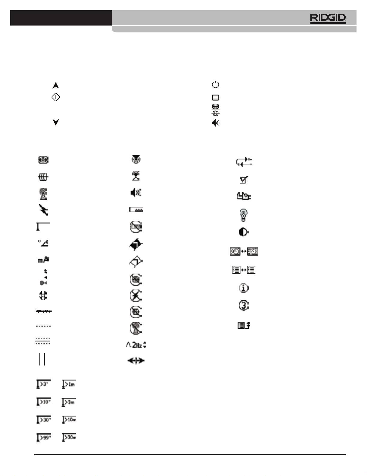
Information Screen and Restoring Defaults
• Information Screen
The information screen appears at the bottom of the menus
choices list. Pressing the Select Key displays information
about your locator, including software version, serial number
of the receiver, and its calibration date (Figure 36).
Figure 36: Information Screen

24
Ridge Tool Company
Tools For The Professional
TM
seekTech sR-20
Menu Tree
SR-20 Maintenance
Activated Frequencies
Sonde
Transportation and Storage
Line Trace
Power (Passive Trace)
Before transporting, make sure that the unit is o to preserve
Radio
battery power.
Units of Measure
When transporting, make sure that the unit is secure and does
F
eet/Meters
not bounce around or get bumped by loose equipment.
Backlight Options
The SR-20 should be stored in a cool dry place.
On/O
/Auto
NOTE: If storing the SR-20 for an extended period, remove
LCD Contrast
the batteries completely.
I
ncrease/Decrease
If shipping the SR-20, remove the batteries entirely from
Display Elements Select
the unit.
(
Check On/O)
Trace Mode Sonde Mode
Maintenance and Cleaning
Watermark
1. Keep the SR-20 clean with a damp cloth and some
Signal Focus Setting
mild detergent. Do not immerse in water.
No-Signal Indicator
2. When cleaning, do not use scraping tools or abrasives
Sound Signals
as they may permanently scratch the display. NEVER
Center Signal Strength*
USE SOLVENTS to clean any part of the system.
Substances like acetone and other harsh chemicals
Signal Strength
can cause cracking of the Case.
Proximity Threshold*
Signal Angle Indicator
Locating Faulty Components
Distortion Line*
For troubleshooting suggestions, please refer to the
Tracing Line Distortion Response*
troubleshooting guide.
Sound Mute > 99’
Service and Repair
Guidance Arrows*
*=Line Trace Display Only
IMPORTANT! Instrument should be taken to a RIDGID
Frequency Select (Check On/O)
Independent Authorized Service Center or returned to the
S
onde
factory. Remove batteries before shipping.
16 Hz, 512 Hz, 640 Hz, 16 kHz, 33 kHz
Line Trace
All repairs made by Ridge service facilities are warranted
128 Hz, 1 kHz, 8 kHz, 33 kHz
against defects in material and workmanship.
Power
If you have any questions regarding the service or repair of
x1
x5
x9
50 Hz
, 50 Hz
, 50 Hz
,
this machine, contact your RIDGID distributor, local RIDGID
x1
x5
x9
60 Hz
, 60 Hz
, 60 Hz
,
oce or Ridge Tool Europe at info.europe@ridgid.com.
100 Hz, 120 Hz, <4 kHz
RF
Low (4-15 kHz)
High (>15 kHz)
Information Menu
Restore Default Settings
(Check Yes/No)
Figure 37: Menu Tree
Ridge Tool Company
25
Tools For The Professional
TM
seekTech sR-20
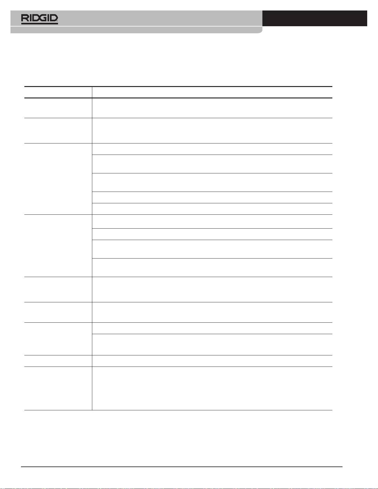
Icons and Symbols
Figure 38: Icons and Symbols
KEYPAD ICONS
Power ON / OFF Key
Menu Navigation/Signal Focus/Proximity Threshold Control
Menu Selection
Menu Key
SondeMode: Force Depth/Re-center Audio
Line Trace Mode: Force Depth, Force current, Re-center Audio
Frequency Key
Signal Strength Proximity Setting: Force Map On
Menu Navigation/Signal Focus/Proximity Threshold Control
Sound Key
DISPLAY ICONS DISPLAY ICONS (Con’t) MENU ICONS
Sonde Frequency
Proximity Signal
Factory Default Reset
Active Trace Frequency
Signal Strength
Menu Check Box
Radio Frequency
Audio Level
Tools Menu
Passive Line Trace Frequency
Battery Level
Backlight settings
Measured Distance/Depth
Low Battery Warning (flashing)
Screen Contrast Adjust
Level Pointer
Signal Angle Indicator
(Signal Strength)
Display Elements
Watermark
Milliamp, Current
(Signal Strength)
Frequency Selection Control
Proximity Threshold Control
No Sonde Present
Information Screen
Pole Icon
No Power Present
Menu Timeout Counter
Tracing Line
No Trace Present
Go Up One Level
Distortion Line
No RF Present
(press menu key)
Equator
Pass Banwidth
Pipe Direction
Line Direction Gradient
Depth Greater Than 3 Feet/1 Meter Threshold
Depth Greater Than 10 Feet/3 Meter Threshold
Depth Greater Than 30 Feet/10 Meter Threshold
Depth Greater Than 99 Feet/30 Meter Threshold
KEYPAD ICONS
Power ON / OFF Key
Menu Navigation/Signal Focus/Proximity Threshold Control
Menu Selection
Menu Key
Sonde Mode: Force Depth/Recenter Audio
Line Trace Mode: Force Depth, Force current, Recenter Audio
Frequency Key
Signal Strength Proximity Setting: Force Map On
Menu Navigation/Signal Focus/Proximity Threshold Control
Sound Key
DISPLAY ICONS
DISPLAY ICONS (Con’t)
MENU ICONS
Sonde Frequency
Proximity Signal
Factory Default Reset
Active Trace Frequency
Signal Strength
Menu Check Box
Radio Frequency
Audio Level
Tools Menu
Passive Line Trace Frequency
Battery Level
Backlight Settings
Measured Distance/Depth
Low Battery Warning (ashing)
Screen Contrast Adjust
Level Pointer
Signal Angle Indicator
(Signal Strength)
Display Elements
Watermark
Milliamp, Current
(Signal Strength)
Frequency SelectionControl
Proximity Threshold Control
No Sonde Present
Information Screen
Pole Icon
No Power Present
Menu Timeout Counter
Tracing Line
No Trace Present
Go Up One Level
Distortion Line
No RF Present
(press menu key)
Equator
Pass Banwidth
Pipe Direction
Line Direction Gradient
Depth Greater Than 3 Feet /1 Meter Threshold
Depth Greater Than 10 Feet /3 Meter Threshold
Depth Greater Than 30 Feet /10 Meter Threshold
Depth Greater Than 99 Feet /30 Meter Threshold
26
Ridge Tool Company
Tools For The Professional
TM
seekTech sR-20
Trouble Shooting Guide
PROBLEM PROBABLE FAULT LOCATION
SR-20 locks up during
Power the unit o, and then back on. Remove the batteries if the unit will not switch o.
use.
If batteries are low, replace them.
SR-20 will not pick up
Check that the correct mode and frequency is set. Examine circuit for possible improvements.
the signal.
Relocate transmitter, change grounding, frequency, etc.; modify Proximity Threshold (page 22)
and/or Signal Focus Control settings (page 22).
While tracing, lines are
This indicates that the SR-20 is not picking up the signal or there is interference.
“jumping” all over the
Make sure that the transmitter is well connected and grounded. Point the SR-20 at either lead to
screen in the mapping
be sure that there is a complete circuit.
display.
Try a higher frequency, or connecting to a dierent point in the line, or switching to inductive
mode.
Try to determine the source of any noise and eliminate it. (Bonded grounding, etc.)
Check SR-20 batteries are fresh and fully charged.
While locating a Sonde,
Check the batteries in the Sonde to see that they are working.
lines are “jumping” all
over the screen.
Sonde may be too far away; try starting with it closer in if possible, or do an area search.
Verify signal by placing lower antenna close to Sonde.
Note – Sondes have diculty emitting signals through cast iron and ductile iron lines.
Increase Proximity Threshold and try lower settings of Signal Focus Control to improve “focus” on
weaker signals.
Distance between Sonde
Sonde may be tilted or there may be a cast-iron-to-plastic transition.
and either Pole is not
equal.
Unit acts erratic, won’t
Batteries may be low. Replace with fresh batteries and power on.
power down.
Display appears
Power the unit o and then back on.
completely dark, or
Adjust the LCD screen contrast.
completely light when
it is turned on.
There is no sound. Adjust the sound level in the sound menu. Verify Proximity Signal is greater than zero.
SR-20 will not power on. Check orientation of batteries.
Check that the batteries are charged.
Check to see that the battery contacts are OK.
Unit may have blown a fuse. (Factory service is required.)

Ridge Tool Company
27
Tools For The Professional
TM
seekTech sR-20
Specications
Default Settings
• Weight w/ batteries .......... 4 lbs. (1.8 kg)
• Depth units = Meter & Centimeter
• Weight w/o batteries ....... 3.3 lbs. (1.5 kg)
• Volume = 2 (two settings above mute)
Dimensions
• Backlight = Auto
•
Length .................................. 11.2” (28.4 cm)
• Proximity Threshold = 30 feet (10m)(Trace)
•
Width ..................................... 4.3” (1.3 m)
• 33 kHz (Active Line Trace Mode)
•
Height .................................... 31.1” (79 cm)
Standard Equipment
Power Source
•
4 C-size batteries, 1.5V Alkaline (ANSI/NEDA 14A, IEC
Item Cat. #
LR14) or 1.2V NiMH or NiCad rechargeable batteries
• SR-20 Locator 21943
•
Power Rating: 6V, 550mA
•
Markers and Mast Holder 12543
• Signal Strength
•
Operator’s Manual
Non-linear in function. 2000 is 10x higher than 1000,
• 4 C-cell batteries (Alkaline)
3000 is 10x higher then 2000, etc.
• Training Video (DVD)
Operating Environment
•
Temperature ........................ -4°F to 122°F (-20°C to 50°C)
Optional Equipment
•
Humidity ............................... 5% to 95% RH
• Additional Sonde Markers 12543
•
Storage Temperature ....... -4°F to 140°F (-20°C to 60°C)
• ST-305 Transmitter 21948
•
ST-510 Transmitter 21953
•
Inductive Clamp (4.75”) 20973
•
Remote Sonde 16728
•
Float Sonde (2pcs) 19793
