ABUS TVVR30004 Operating instructions – page 5
Manual for ABUS TVVR30004 Operating instructions
Table of contents
- User guide
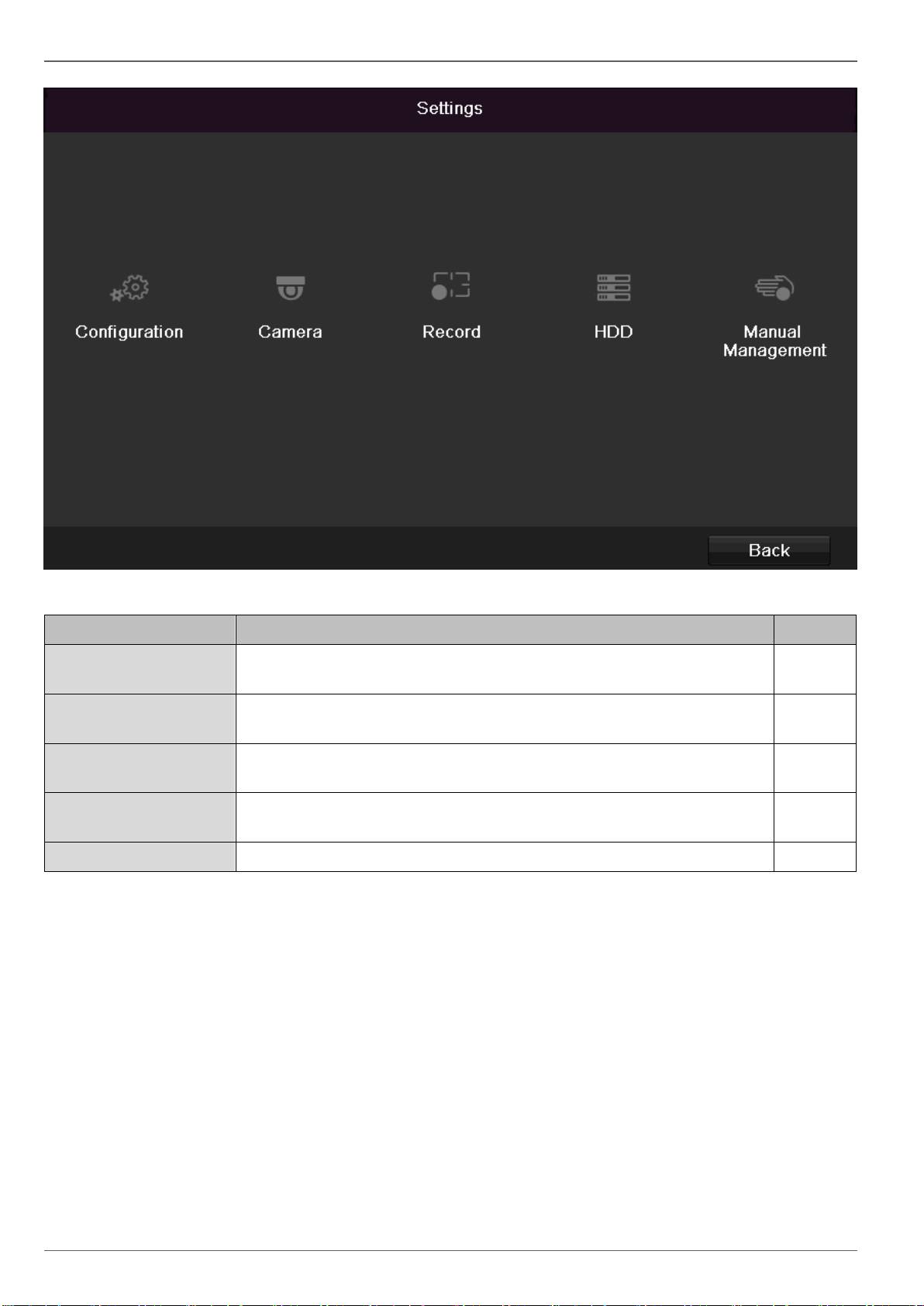
Main menu
Menu description
81
Menu
description
page
Configuration
Used for managing all device settings (General, Network, Live View, Excep-
tion, User).
82
Camera
Menu for setting camera parameters (OSD configuration, image mode, mo-
tion recognition, Private Zone, Tamper Monitoring, Video Loss).
90
Record
Menu to set recording parameters (time plan, camera resolution, camera
stream etc.).
94
HDD
Used for initialising or managing installed HDD (assigning read/write func-
tions, cameras, network HDD management etc.).
97
Manual Management
Menu for setting manual recordings.
99
Configuration
Configuration
82
Note
The “Configuration” menu is used to manage all
device settings.
Warning
Ensure that the date and time are set correctly.
IMPORTANT:
Subsequent changes to the settings can lead
to data loss!
Ensure a data backup has been made in good
time beforehand.
Overview
Menu
Setting
Page
General
Language, video, time, date,
mouse pointer, password, time
zones and other settings
82
Network
Required network settings
(manual IP, DHCP, PPPOE,
DDNS etc.)
83
Warning
Behaviour of the device in ex-
ceptional cases
(HDD full, network disconnect-
ed etc.)
88
User
Adding and changing users,
assigning authorisation rights
88
Note
Pay attention to the instructions in the correspond-
ing sections.
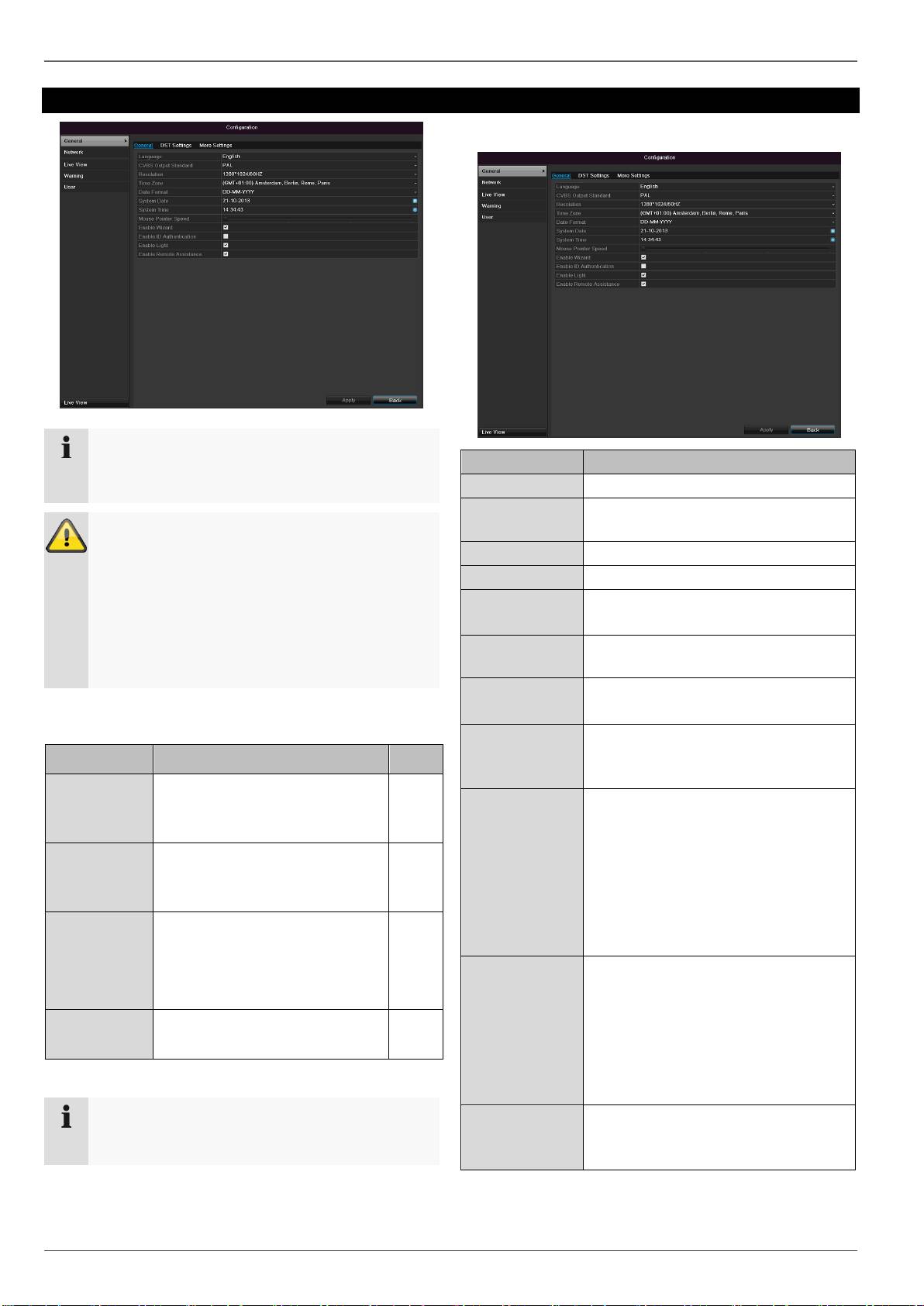
General
“General” tab
Setting
Language
Language on the OSD
CVBS Output
Standard
PAL / NTSC
Resolution
Resolution on the monitor
Time Zone
GMT (Greenwich Mean Time)
Date Format
MM-DD-YYYY, DD-MM-YYYY,
YYYY-MM-DD
System
Date/Time
Date and time
Mouse Pointer
Speed
Set on the scroll bar (left =
low speed; right = high speed)
Enable Wizard
Box ticked:
Wizard will appear after restart of the
device.
Enable ID Au-
thentification
Box not ticked:
In order to enter a menu no password
has to be entered. At access by net-
work the password has to be entered.
Box ticked:
Password must be entered in order to
use the menu.
Activating LED
status bar
Box not ticked:
The LED status display is deactivat-
ed.
Box ticked:
The LED status display glows blue
when the recorder is on.
Activate remote
access
Box ticked:
Access for remote configuration is ac-
tivated for technical support.
Configuration
83
Note
Activate remote access
Activate this function to enable optimum technical
support.
TAB “DST set-
tings”
Setting
Auto DST Ad-
justment
With an activated check box, the de-
vice converts automatically to summer
time.
Enable DST
With an activated check box, an exact
start / end date can be selected
From / To
Date of DST start / end
DST Bias
Daylight Saving Time Bias: Correc-
tion of the DST to the reference time
TAB “More
Settings”
Setting
Device Name
Unique specification of the device
Device Number
Used for unique identification when
using remote control
CVBS Output
Brightness
Scroll bar (left = darker;
right = brighter)
Operation
Timeout
Never / 1 to 30 minutes – regulates
how long the menu is shown
Output mode
menu
Renders the image softer or sharper
Event message
Box ticked:
Automatic alarming when notifica-
tions such as motion detection , HDD
full, etc. occur.
Confirm the settings by clicking Apply and leave the
menu with OK.
Network configuration
Correct network settings are essential in the following
cases:
When using remote control of the device and surveil-
lance over your server
Note
Please read the following basic instructions before
setting up the device.
Terms and definitions
An overview of relevant terms when using the device in a
network can be found below.
A network is a connection of at least two network-capable
devices.
Transmission types:
Wired networks (e.g. CAT5 cable)
Wireless networks (WLAN)
Other transmission types (Powerline)
All systems have certain similarities, but can also differ in
many ways.
Parameter
Setting
IP address
An IP address is the unique address of a
network device within a network.
This address may only appear once with-
in a network. Certain IP address ranges
are reserved for public networks (e.g. the
Internet).
Private
address
range
e.g. 10.0.0.0 – 10.255.255.255
Subnet mask: 255.0.0.0
172.16.0.0 - 172.31.255.255
Subnet mask: 255.255.0.0
192.168.0.0 - 192.168.255.255
Subnet mask: 255.255.255.0
Subnet
mask
A subnet mask is a bit mask used for
making decisions and assignments dur-
ing routing.
255.255.255.0 is the standard subnet
mask in home networks.
Gateway
A gateway is a network device which al-
lows all other network devices to access
the Internet.
This can be the computer connected to
the DSL modem or – usually – the router
or access point within the network.
Parameter
Setting
Name
server
The name server is responsible for as-
signing a unique IP address to a web ad-
dress or URL (e.g. www.google.de). Also
known as DNS (Domain Name Server).
When a domain name is entered into a
browser, the DNS searches for the cor-
responding IP address of the server and
forwards the query on.
The IP of the provider’s DNS can be en-
tered here. However, it is often sufficient
to select the IP of the gateway. This then
forwards the queries independently to the
provider DNS.
DHCP
The DHCP server automatically assigns
the IP address, subnet mask, gateway
and name server to a network device.
DHCPs are available in current routers.
The DHCP service must be specially set
and activated (see the corresponding
manual for more information).
Note:
When using fixed IP addresses and a
DHCP server, make sure that the fixed IP
addresses are outside the address range
assigned by DHCP. Otherwise, problems
could occur.
Configuration
84
Port
A port is an interface used for communi-
cation by different programs. Certain
ports are fixed (23: Telnet, 21: FTP),
whilst others can be freely selected.
Ports are important for different applica-
tions (e.g. external access to the device
over a browser).
MAC
address
The MAC address (Media Access Con-
trol or Ethernet ID) is the specific hard-
ware address of the network adapter.
This is used for the unique identification
of the device in a computer network.
Network layout
The device must be physically connected to the network
over a CAT5 cable (see the connections on page 60).
Note
Pay attention to the specific information and in-
structions on the network devices.
Several switches, routers and access points can be con-
nected to each other. Firewalls and other security soft-
ware can affect the network.
Warning
When using a router, the network clients (e.g. the
recorder) can be connected to the Internet and
vice versa.
Make sure to use protective measures to prevent
unauthorised external access (e.g. firewall, chang-
ing passwords, changing ports)!
Network-configuration
TAB
Settings
General
Settings for the local net and selecting
the network mode.
PPPOE
PPPOE is used on ADSL connections
and when using modems in Germany.
Click on “Set” to enter the access data
(ID and password) for your provider.
DDNS
Server for Dynamic Domain Name Sys-
tem management. Used for updating
host names or DNS entries
NTP
Network Time Protocol
Server for time synchronisation
Used to specify the e-mail settings
which are sent as an e-mail to a specif-
ic address in the event of an alarm.
UPnP
Universal Plug and Play
Settings for the convenient control of
network devices in an IP network.
More
Settings
Used to configure the IP address of the
PC where a message should be dis-
played in the event of an alarm
Configuration
TAB General
85
Parameter
Setting
NIC Typ
Set the transmission speed of the in-
stalled network card here.
Tip: 10M/100/1000M self adaptive
Enable DHCP
Tick the box if the IP addresses are
assigned dynamically via DHCP in the
network.
DHCP activated: Subsequent entry
fields are inactive (parameters as-
signed via DHCP).
Note:
If the IP addresses are assigned man-
ually, ensure that DHCP is not active
(box not ticked).
IPv4 Adress
Address of the network device in the
network (manual assignment)
IPv4
Subnet Mask
Usually 255.255.255.0
IPv4 Default
Gateway
Address of the gateway for Internet ac-
cess
IPv6 Adress 1
Currently no functioning
IPv6 Adress 2
Currently no functioning
IPv6 Standard
Gateway
Currently no functioning
MAC Adress
Hardware address of the installed net-
work card
MTU (Bytes)
Describes the max. size of the largest
protocol data .
Preferred
DNS Server
Address of the Domain Name Server
(usually the IP address of the gateway)
Alternate DNS
IP address of the alternative DNS
server
Report net-
work interrup-
tion
Box ticked:
Acoustic alarm in the event of a net-
work interruption
Note
In certain modes some of these settings cannot be
selected.
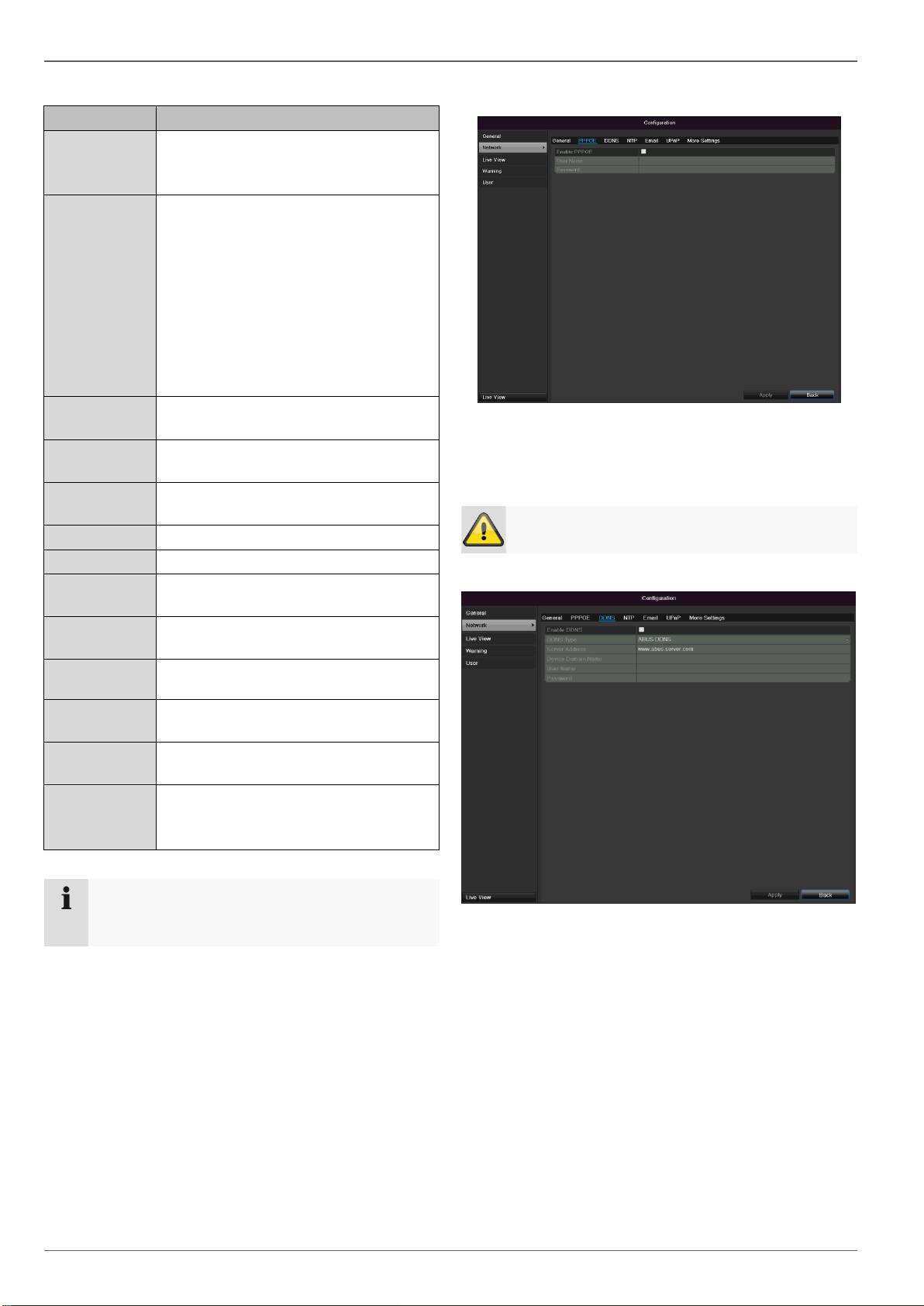
PPPOE
1.
Tick the PPPOE box, enter the user name (Internet
access ID) and password, then confirm the pass-
word.
2.
Confirm the settings by pressing Apply.
Warning
Use PPPOE only if there is no router available.
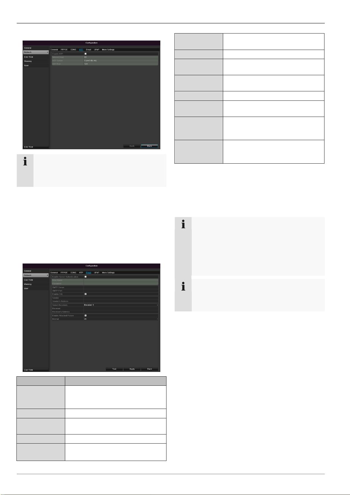
DDNS
1.
To use the ABUS DDNS function, you must first set
up an account under www.abus-server.com. Please
note the FAQs on the website when doing this.
2.
Tick the “Enable DDNS” box, enter ‘ABUS DDNS’ as
the “DDNS Type”, then enter www.abus-server.com
or “62.153.88.107” under “Server Address”.
3.
Confirm the settings by pressing Apply. The IP ad-
dress of your Internet connection is now updated on
the server every minute.
Configuration
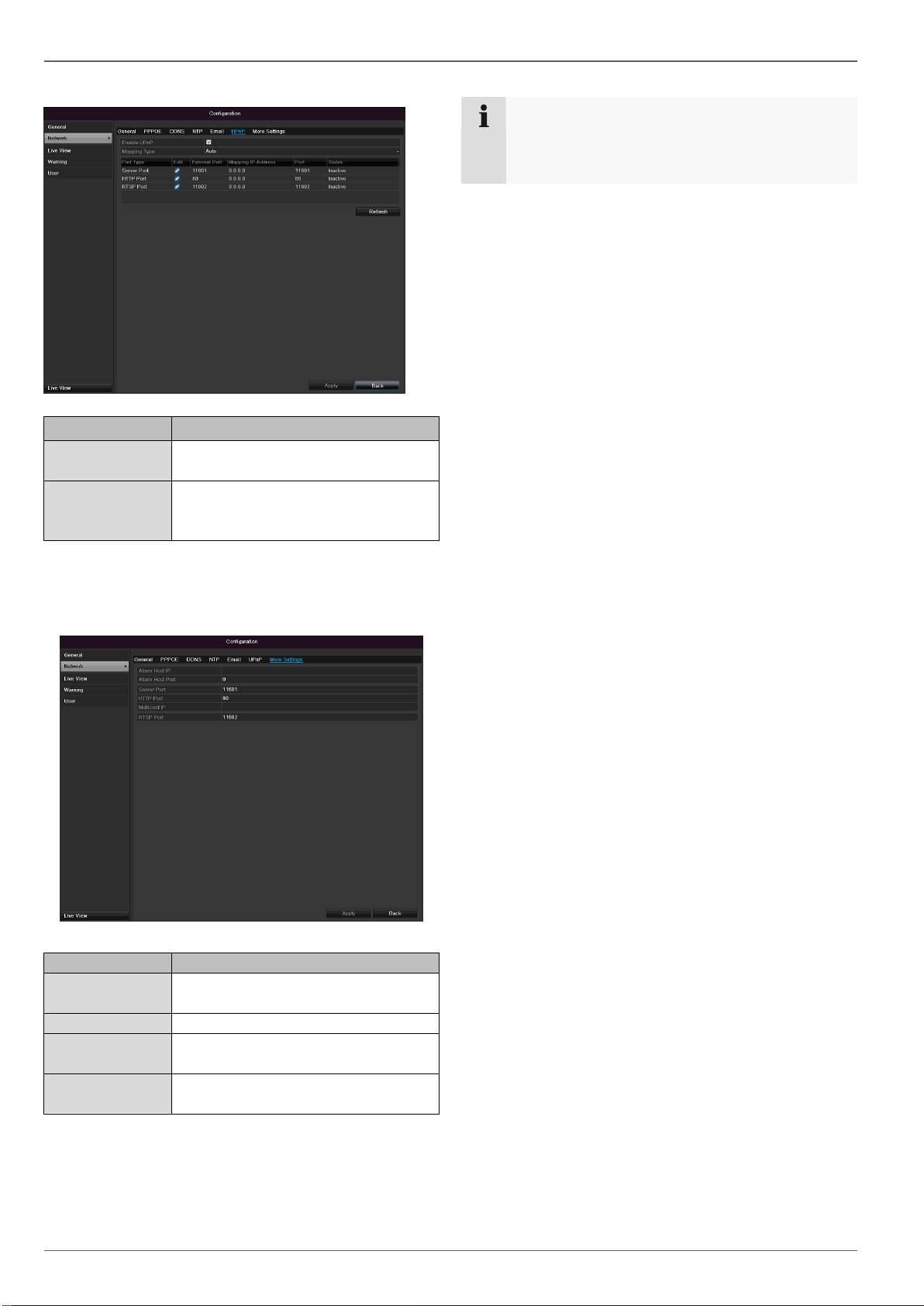
NTP
86
Note
The recorder can synchronise the time with an ex-
ternal server. Several server addresses are avail-
able on the Internet for this purpose.
1.
Tick the “Enable NTP” box and then enter the inter-
val at which the synchronisation should be made
again. Enter the IP address of the NTP server and
the NTP port.
2.
Confirm the settings by pressing Apply.
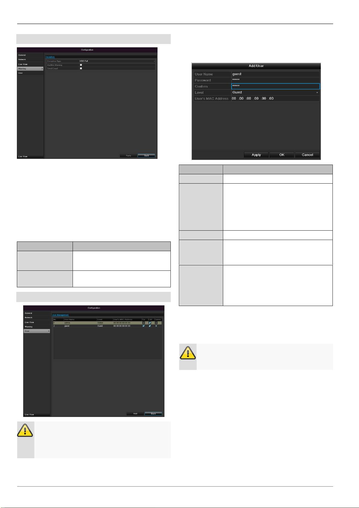
In the event of an alarm, the device can send a message
by e-mail. Enter the e-mail configuration here:
Parameter
Setting
Enable Server
Authentica...
Tick the box when authentication is
made on the server of the Internet
provider
User Name
E-mail account at the provider
Password
Password connected to the e-mail
account
SMTP Server
SMTP server address of the provider
SMTP Port
Enter the SMTP port here
(Default: 25)
Enable SSL
Tick the box to activate the e-mail
encryption
Sender
Name of the sender
Sender´s
Adresse
Corresponding e-mail address for
the e-mail account
Sender´s Recei-
ver
Select three possible recipients for
the e-mail
Receiver
Enter the name of the recipient here
Receiver´s Ad-
resse
Enter the e-mail address of the
recipient here
Enable Attached
Picture
Tick the box when camera images
should also be sent with the e-mail
as photo files
Interval
Select the interval between the
individual recordings (2 to 5 sec-
onds)
1.
Enter the parameters of the e-mail notification.
2.
Click on Test to send a test e-mail.
3. Please clarify if your settings are correct and you
have received a confirmation mail. Then click on
Apply.
Note
The device sends an e-mail to the specified recip-
ients.
If the e-mail is not received, check the settings
and correct them.
If necessary, check the spam filter of your e-mail
client.
Note
Because of the cause of compatibility please do
only use E-Mail clients where a dial-up via SMTP
is possible.
Configuration
UPnP
87
Parameter
Setting
Enable UPnP
Tick box to activate visibility in an IP
network.
Mapping Type
Select here whether port mapping is
to be conducted automatically or
manually.
Confirm the settings by clicking Apply and exit the menu
with Back.
More settings
Parameter
Setting
Server Port
Port for data communication (Gen-
eral: 8000)
HTTP Port
Port for web server (General: 80)
Multicast IP
In order to minimize traffic you can
enter a Multicast IP.
RTSP Service
Port
RTSP-port
(Default: 554)
Note
Server port 8000 and HTTP port 80 are the stand-
ard ports for remote clients and remote Internet
browser access.
Configuration
Warning
You can trigger a warning for the following error types:
HDD Full
HDD Error
Network Disconnected
IP Conflict
Illegal Login
Video input/output signals not equal
Exception Error
88
Parameter
Notifications
Audible Warning
The device emits a repeating tone.
Send E-mail
An e-mail is sent to a specific e-
mail address. See page 86
User
Warning
Note down the admin password.
The following password is preset
“1 2 3 4 5”
You can add new users, delete existing users and
change the settings in the “User Management” menu.
1.
To add a new user, select Add.
Parameter
Setting
User Name
Unique identification
Password
Access code for the device (device
management)
Note: Change all passwords on a regu-
lar basis, using a combination of letters
and numbers. Note down all pass-
words in a safe place.
Confirm
Enter the access code again here
Level
IMPORTANT:
More access rights can be set on the
Manager level than on the User level.
User's MAC
Address
MAC address of the network adapter
on the PC of the corresponding user
Note:
This limits access to the PC whose
MAC address is entered here!
2.
Enter the name and password and confirm the
password in the field below.
3.
Select the level and enter the MAC address.
4. Confirm the settings by clicking Apply.
Warning
Pay attention to the instructions below on assign-
ing access rights.
Configuration
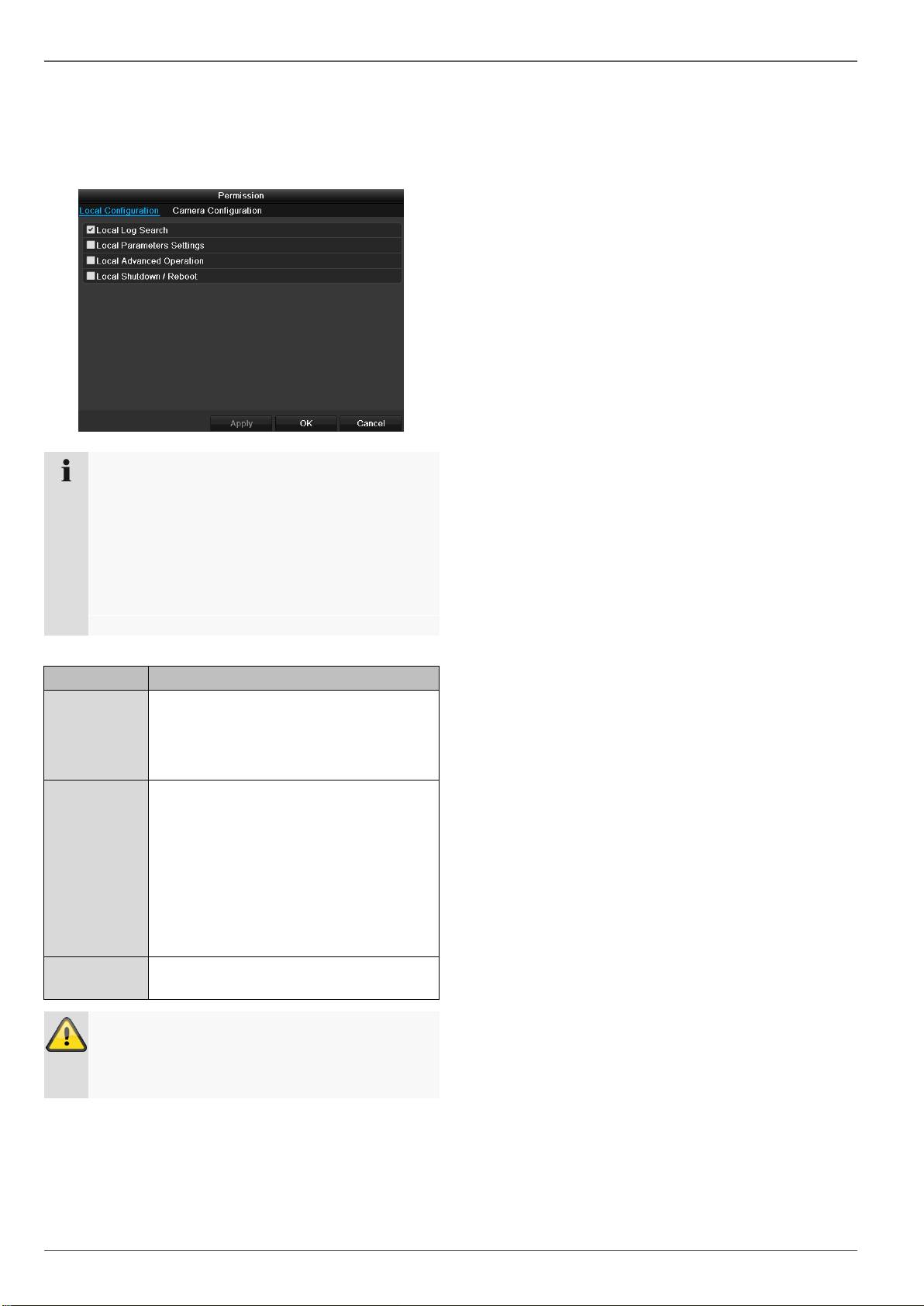
Permission
Control the access rights of the user by clicking the
“Permission” symbol. Only the access data of users add-
ed manually can be changed:
89
Note
The user can make the settings locally (i.e. on the
device) or change the parameters.
The user can access the device via the network
connection.
The “Camera Permission” tab is used to set ac-
cess rights for individual cameras (network or lo-
cal).
Parameter
Setting
Local
Configuration
Local Log Search
Local Parameters Settings
Local Advanced Operation
Local Shutdown / Reboot
Remote
Confguration
Remote Log Search
Remote Parameters Settings
Remote Serial Port Ctnrol
Remote Video Output Cntrol
Two-way Audio
Remote Alarm Control
Remote Advanced Operation
Remote ShutDown / Reboot
Camera
Configuration
Camera Permission
Warning
Change the general settings of the user (name,
password, level, MAC address) by clicking the
“Edit” symbol or in the TAB “Change password”.
Camera
Camera
OSD
90
Camera
Camera to be set
Camera Name
Allocation of camera name
Display Name
Activate / deactivate display of
camera name in the live view
Display Date
Activate / deactivate display of
date in the live view
Display Week
Activate / deactivate display of
week in the live view
Date Format
Selection of date display type
Time Format
12 hours / 24 hours
Display Mode
Settings relating to the presenta-
tion of camera name and date
OSD font
Changing the font size
Motion
Select the camera channel under “Camera”.
Select the checkbox for the motion detection.
Handling
Trigger Channel
When “Reaction” is clicked, the TAB Trigger channel
appears (only with motion recognition):
Image
Select one or more camera channels that should carry
out a reaction in the event of an alarm.
Confirm the settings by clicking Apply and leave the
menu with OK.
Select the camera channel to be processed at “Camera”.
Adapt the camera image to light conditions at “Mode” by
means of specified settings or with user-defined settings.
Note
In order to record using the motion recognition, you
must set the time plan at recording (see p.94).
Camera
Armin Schedule
Select the TAB Arming Schedule.
Here you set the times when the reactions in the TAB
Reaction are triggered.
1. Select the day and enter the schedule.
2. Select whether the settings should be applied to all
days of the week with using Copy.
3. Confirm the settings by clicking Apply and leave the
menu with OK.
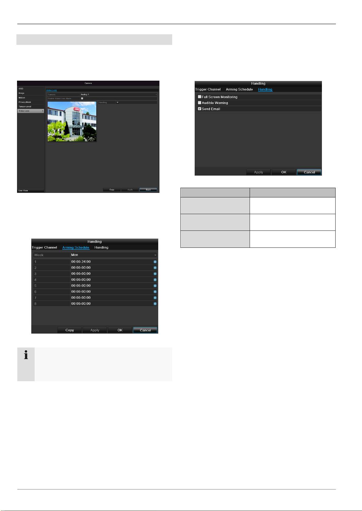
Handling
Click on the TAB Handling.
Here you can configure the behavior of the recorder dur-
ing a detected event (for example: motion got detected)
by clicking the respective check box.
91
Parameter
Notification
Full Screen Monitoring
The camera is displayed as a
full-screen picture in live cast
Audible Warning
The device emits a repeating
tone
Send E-Mail
An e-mail is sent to a specific
e-mail address (see page 86)
Confirm the settings by clicking Apply and leave the
menu with OK
Private Zone
Select the camera channel under “Camera”.
Select the checkbox for activating the private zone.
1. Select up to four private zones with the mouse.
2. Select Copy if the setting is to be applied for all
cameras.
3. Confirm the settings by clicking Apply and exit the
menu with OK.
Note
You can define up to 8 time periods (each from
00:00 to 00:00). The times in the individual peri-
ods must not overlap.
Camera
Tamper monitoring
Select the camera channel under “Camera”.
Select the checkbox for activating tamper monitoring.
Armin Schedule
Select the TAB Arming Schedule.
Here you set the times when the reactions in the TAB
Reaction are triggered.
1. Select the day and enter the schedule.
92
Note
You can define up to 8 time periods (each from
00:00 to 00:00). The times in the individual peri-
ods must not overlap.
2. Select whether the settings should be applied to all
days of the week with using Copy.
3. Confirm the settings by clicking Apply and leave the
menu with OK.
Handling
Click on the TAB Handling.
Here you can configure the behavior of the recorder dur-
ing a detected event (for example: motion got detected)
by clicking the respective check box.
Parameter
Notification
Full Screen Monitoring
The camera is displayed as
a full-screen picture in live
cast
Audible Warning
The device emits a repeat-
ing tone
Send E-Mail
An e-mail is sent to a specif-
ic e-mail address (see page
86)
Confirm the settings by clicking Apply and leave the
menu with OK
Camera
Video signal loss
Select the camera channel under “Camera”.
Set the checkmark for the alarm in the event of a “Video
Loss”.
Armin Schedule
Select the TAB Arming Schedule.
Here you set the times when the reactions in the TAB
Reaction are triggered.
1. Select the day and enter the schedule.
93
Note
You can define up to 8 time periods (each from
00:00 to 00:00). The times in the individual peri-
ods must not overlap.
Handling
Click on the TAB Handling.
Here you can configure the behavior of the recorder dur-
ing a detected event (for example: motion got detected)
by clicking the respective check box.
2. Select whether the settings should be applied to all
days of the week with using Copy.
3. Confirm the settings by clicking Apply and leave the
menu with OK.
Parameter
Notification
Full Screen Monitoring
The camera is displayed as a
full-screen picture in live cast
Audible Warning
The device emits a repeating
tone
Send E-Mail
An e-mail is sent to a specific
e-mail address (see page 86)
Confirm the settings by clicking Apply and leave the
menu with OK
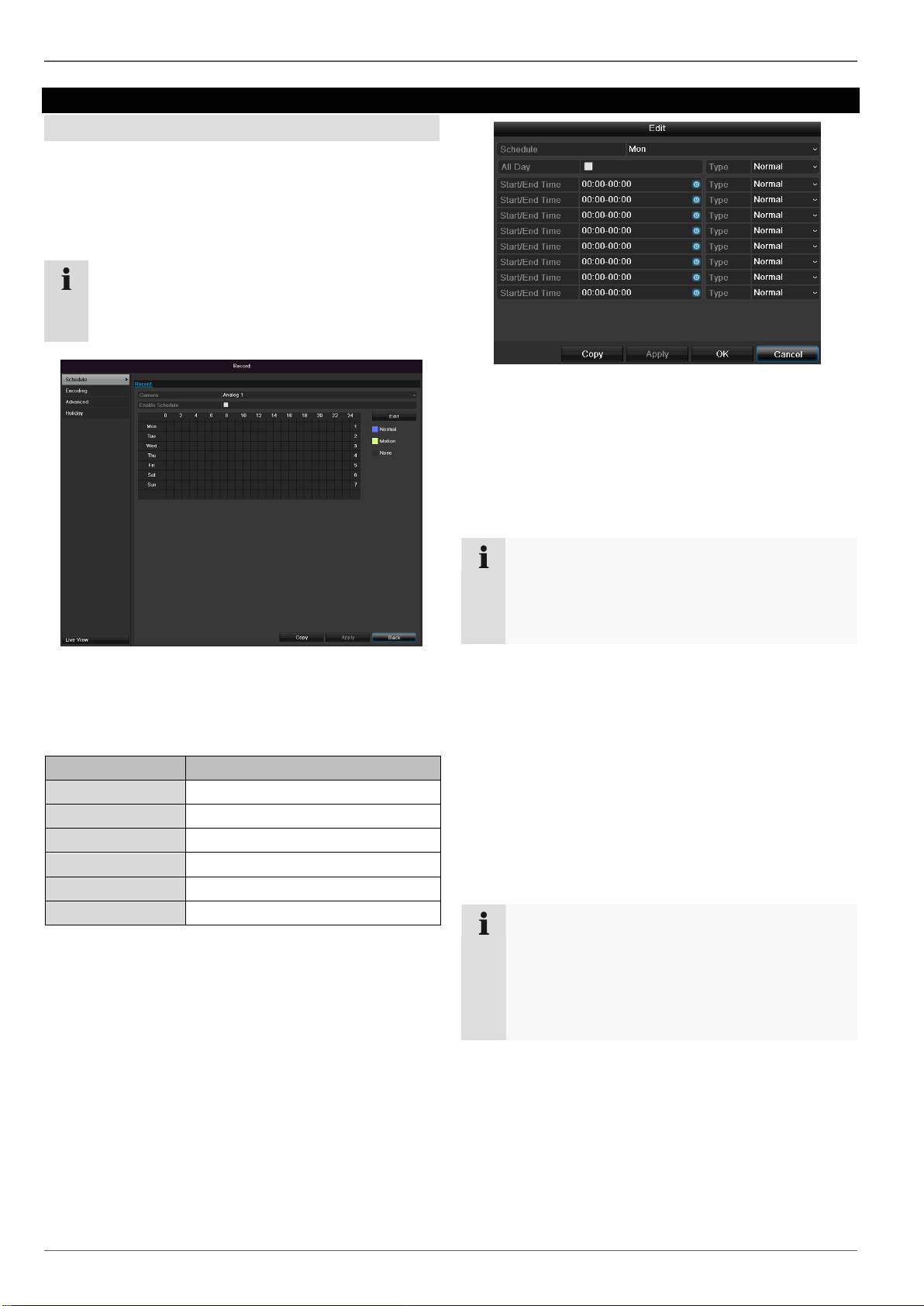
Record
Record
Setting up
Open the main menu and click on record:
Schedule
The schedule is used to specify the recording times and
triggers (recording type) for the cameras. Click on the
“Schedule” tab:
94
Note
Because there is no difference between the set-
tings for the TABs record and instant image, these
are only listed once.
In the OSD, the hours of the respective days are listed
from left to right (the days are listed from top to bottom).
A colour key is shown underneath the days (i.e. the re-
cording periods in the schedule are shown in colour ac-
cording to the trigger (recording types)).
Colour symbol
Key
Blue
Normal recording: Period in hours
Yellow
Motion detection
Light blue
Motion detection and alarm
Red
Alarm
Grey
No selection
Brown
Motion or alarm
1. Define the day to be set in the pull-down menu at
‘Schedule’.
2. Activate/deactivate ‘All day’. If the full day is active, no
definite times can be entered as the setting is now val-
id for the whole day.
3. To make specific time settings, deactivate the “All
Day” box.
4. Specify the recording type in the drop-down menu:
Time
Motion detection
Alarm
Motion detection or alarm
Motion detection and alarm
5. When making a specific time setting, you can define
up to 8 time periods (each from 00:00 to 24:00). The
times in the individual periods must not overlap.
Select the camera and click on the check box Ena-
ble Schedule.
Click on Edit to specify the type and duration of the
time plan
Note
The “Time” recording type defines the time win-
dow where a recording is made.
The other events (e.g. motion detection and/or
alarm) only trigger the recording after the specific
event has occurred.
At Copy you can take on this setting for other days or
the whole week.
6. Finalize your settings in the record screen with Apply
and then OK.
Application example
Recording should run from 11:00 to 07:00. 2 time
zones must be set up for this:
1. 11:00 AM - 24:00PM
2. 00:00 AM - 7:00 AM
Encoding
Encoding
Record
The schedule is used to specify the recording times and
triggers (recording type) for the cameras.
The following setting options are available in this sub-
menu:
95
Camera
Camera to be set
Encoding Para-
meter
Stream to be set
Stream Type
Predefined video stream
Resolution
Auto, WD1 (960x480)
4CIF (704x576),
2CIF (704 x 288), CIF (352x288),
QCIF (176x144)
Bit rate
Select a variable or constant bit
rate
Video Quality
There are various quality levels:
+++: medium quality
++++++: high quality
Frame rate
Setting for the stream frame rate
Max. bit rate mo-
de
Select the mode for setting the bit
rate
User def. (32 – 3072)
Max. bit rate
(kbps)
Setting for the maximum bit rate
Recommended
max. bit rate
Recommended bit rate depending
on the set resolution, frame rate,
etc.
Lead time
Recording period before an
alarm (in seconds)
Overrun time
Recording period after an alarm
(in seconds)
Mark elapsed ti-
me
Setting for the longest retention
time for recorded files.
Activate 960 mo-
de
Activated:
Recording with WD1 resolution
possible.
Confirm the settings by clicking Apply and exit the menu
with OK.
TAB Substream
The following parameters can be set:
Camera
Camera to be set
Stream Type
Predefined video stream
Resolution
Auto, 4CIF (704x576), CIF
(352x288), QCIF (176x144)
Bit Rate Type
Select a variable or constant bit
rate
Video Quality
There are various quality levels:
+++: medium quality
++++++: high quality
Frame rate
Setting for the stream frame rate
Max. bit rate mo-
de
General,
user def. (32 – 3072
Max. bit rate
(kbps)
Display of the maximum bit rate
Recommended
max. bit rate
192~320 (kbps)
Confirm the settings by clicking Apply and exit the menu
with Back.
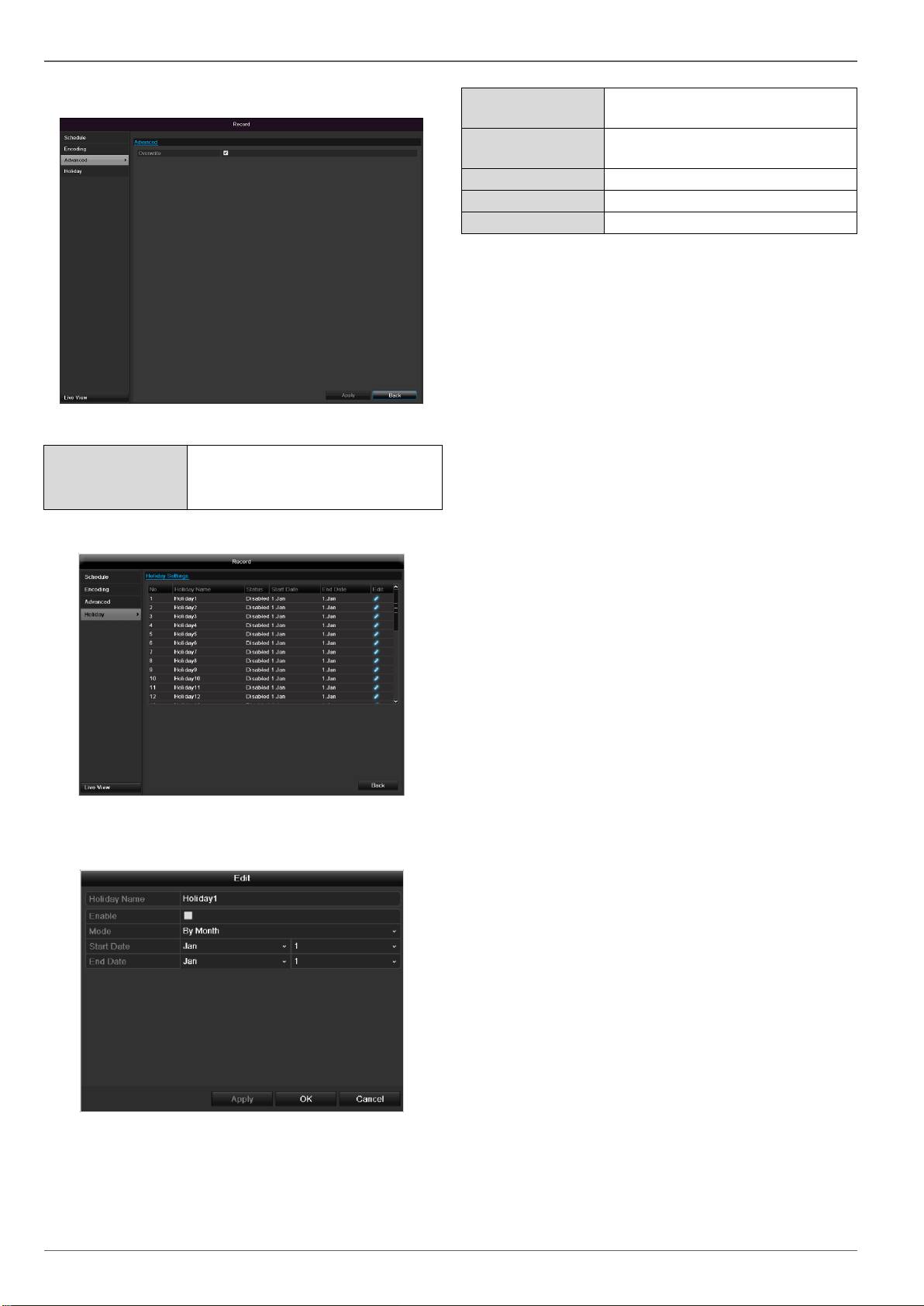
Encoding
Advanced settings
96
Overwrite
You can specify whether older re-
cordings are deleted when the
HDD memory is full
Holidays
In this sub-menu, 32 different recording settings for vaca-
tions or public holidays can be applied.
To apply these settings click on the “Edit” symbol:
Holiday Name
Manual name entry of the vaca-
tion or holiday
Enable
Activate or deactivate the set va-
cation
Mode
According to date / week / month
Start Date
Selection of start date / start time
End Date
Selection of end date / end time
Confirm your settings with Apply and OK.
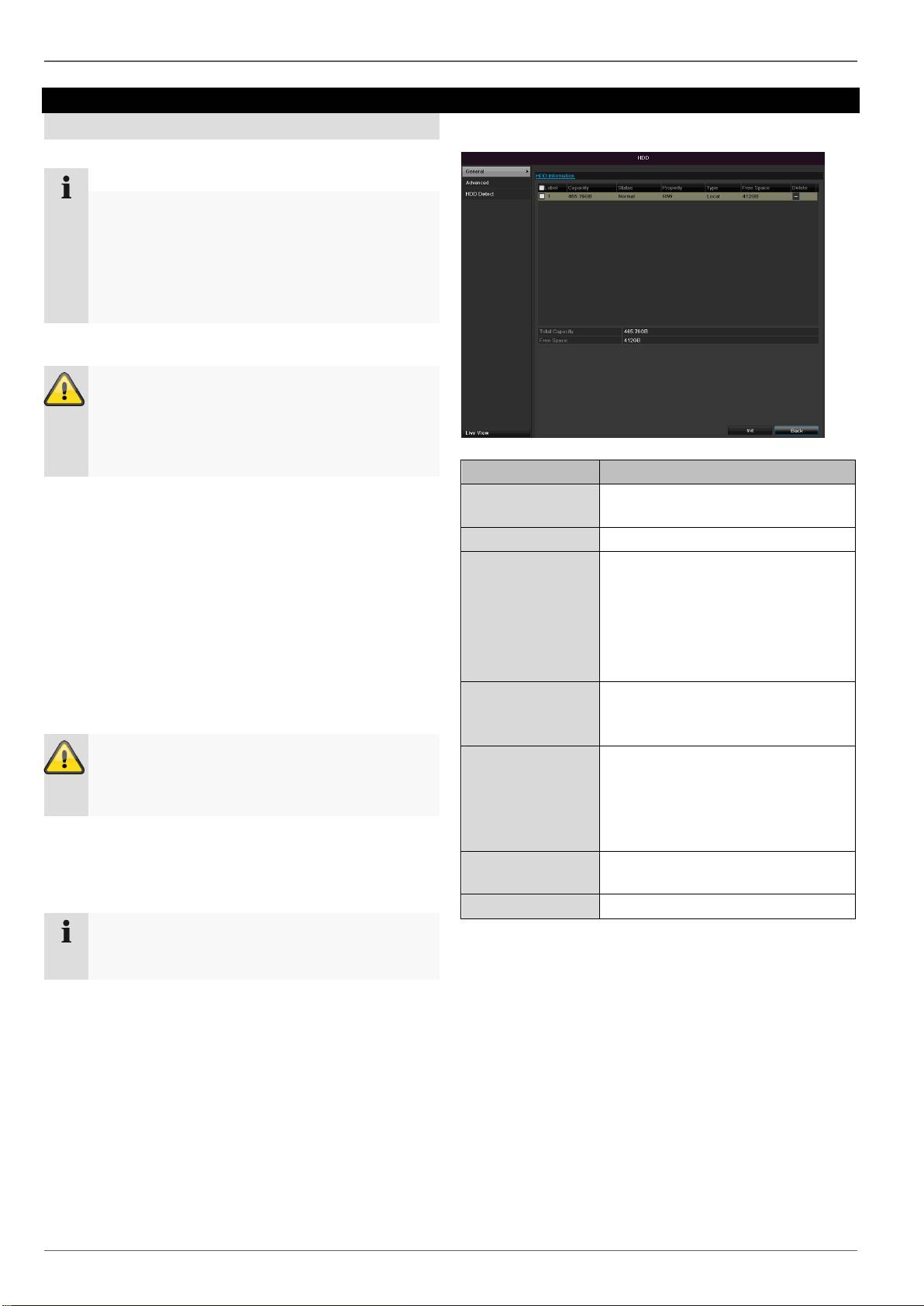
HDD
HDD
HDDs
97
Note
The device can manage one 2.5" SATA hard disk
drive.
Each of the installed HDDs must be initialised be-
fore the device can be used for recording. The de-
vice only detects the HDD and its assignment af-
ter initialisation has been made.
Warning
All data is deleted from the HDD during initialisa-
tion.
Ensure a data backup has been made in good
time beforehand.
Installing the HDD
1.
Disconnect the device from the mains power and
open the cover.
2.
Observe the applicable ESD guidelines when han-
dling electronic devices and ensure they are earthed.
3.
Do not open the device in rooms with carpets or oth-
er surfaces that can become electro statically
charged.
4.
Avoid bodily contact with all components on the
PCB.
Warning
If you have questions regarding the information or
cannot find the information you need, please con-
tact your maintenance specialist.
5.
Install the HDD and then connect it.
6.
HDD Management parameters
Reattach the cover and connect the device to the
mains power supply.
Click on “HDD” in the menu to define settings relating to
hard disc administration
HDD information
No.
Shows the internal connection
number
Capacity
HDD capacity (in GB)
Status
Shows the current status of the
HDD:
Not initialised
Normal
Error
Standby
Features
Read-only: Read-only protec-
tion
R/W: Read and write
Type
Local: Device HDD
NFS: Network HDD
If possible, avoid using NFS stor-
age due to compatibility problems
that may occur.
Free Space
Shows the approximate free
memory for recordings
Delete
Remove the hard drive
1.
Select the HDD by ticking the corresponding box.
2.
Start the process by clicking on Init.
3.
Confirm the prompt by pressing OK.
4.
The status bar shows the progress of the initialisa-
tion.
5. Nach Beendigung des Vorgangs erscheint die Fest-
platte.
Note
If the initialised HDD is not displayed, check the
connections
HDD
This information helps to recognise hard disc errors. For
HDD settings of the cameras
this reason, do not deactivate this feature if possible.
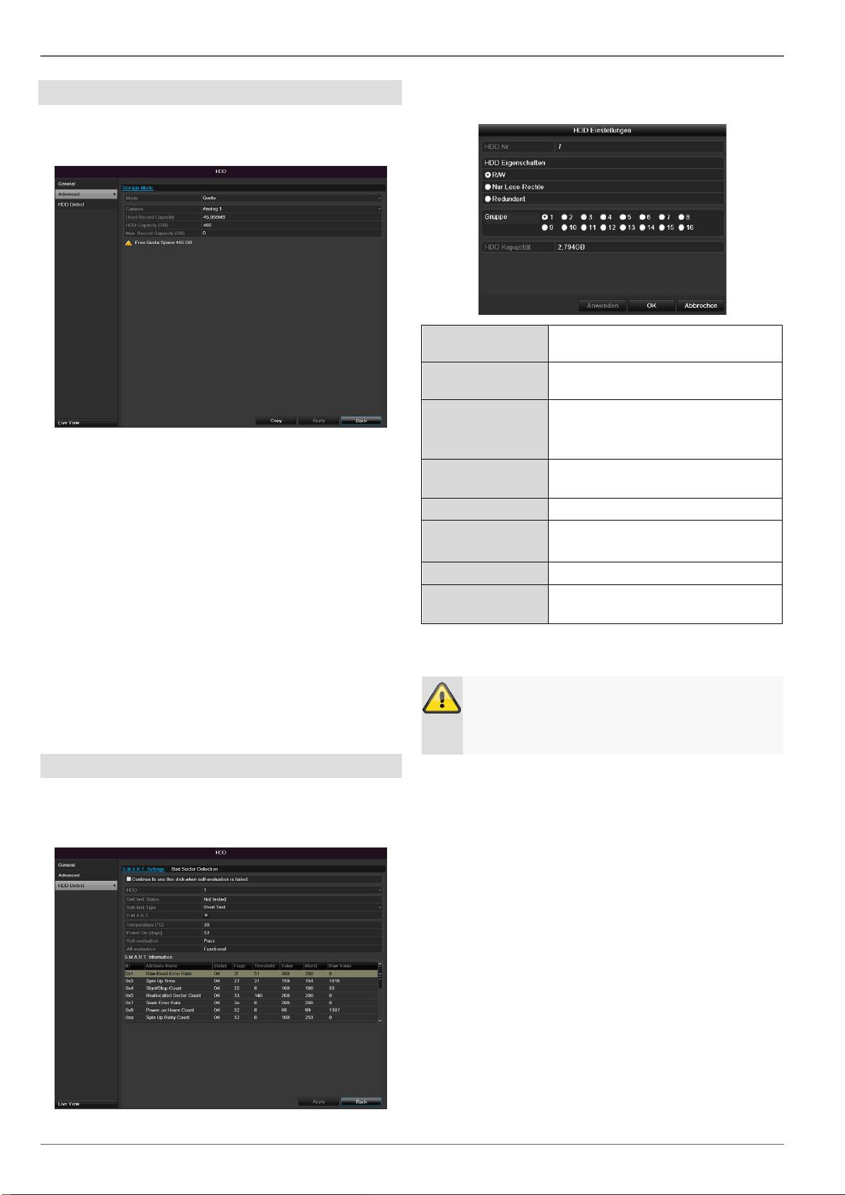
Click on the “Advanced” submenu
Mode: Storage
Camera
Selection of the camera channel for processing.
Used Record Capacity
File size of a recording file
HDD capacity (GB)
HDD capacity (in GB)
Max. capacity (GB) for recordings
Specify the maximum recording size on the hard
disk drive for each camera.
1. Select Copy if the setting is to be applied for all cam-
eras.
2. Confirm the settings by clicking Apply and exit the
menu with OK.
3. Click Apply and confirm the restart in the next win-
dow with OK.
S.M.A.R.T.
S.M.A.R.T. means Self-Monitoring Analysis and Report-
ing Technology. Click on the “S.M.A.R.T” submenu.
98
HDD
Selection of the hard disk drive to
be processed.
Self-test status
Shows the status of the current self-
test
Self-test type
Select the type of the self-test.
Short Test / Expanded Test /
Transport Test
S.M.A.R.T
Click on the icon to start the self-
test
Temperature (°C)
Display the HDD temperature
Switching on
(Days)
Display the operating days of the
hard disk drive
Self-evaluation
Status display of the self-evaluation
Complete evalua-
tion
Status display of the evaluation
Confirm the settings by clicking Apply and exit the menu
with OK.
Important:
If only one HDD is installed and this is set to
“Read-only”, then the device cannot make re-
cordings.
Checking the HDD status
The status of each HDD can be checked in the “Mainte-
nance” menu. S.M.A.R.T. information (Self-Monitoring,
Analysis and Reporting Technology) is stored in the log
data.
Call up the log file and search according to the infor-
mation/S.M.A.R.T. HDD (see page Fehler!
Textmarke nicht definiert.).
You can specify alarms to inform you of HDD errors.
To do this, call “Warning” in the “Settings” menu.
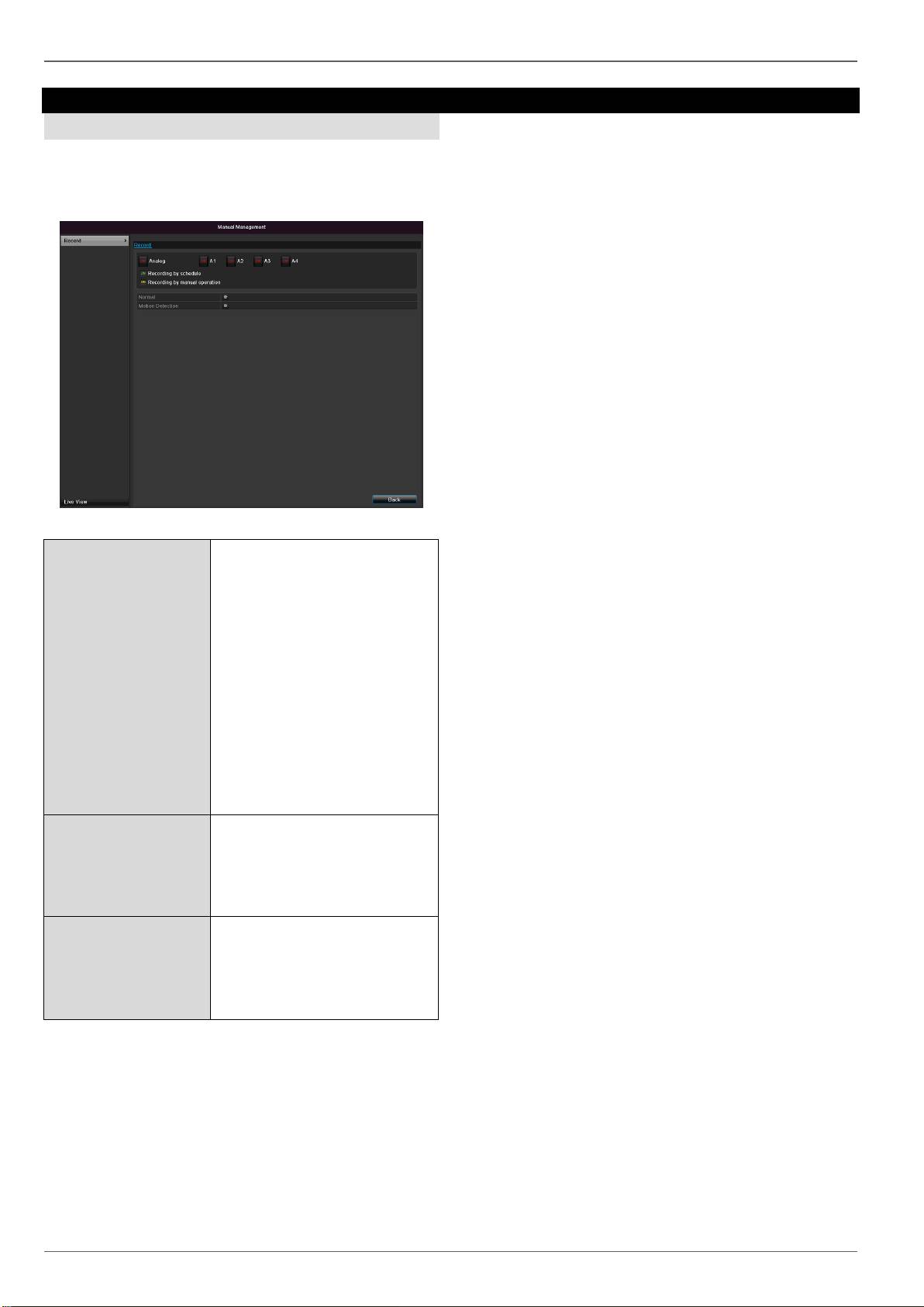
Panic recording
Panic recording
Recording
Press the REC button or navigate to Panic Recording in
the main menu to start manual picture/video recording.
Click on the “Recording” submenu.
99
Analog
Select the settings for all cam-
eras
Click “Off” or “On” to change
the settings.
On, green:
Recording according to sched-
ule,
On, yellow:
Recording with manual opera-
tion
Off, red:
No recording.
Duration
Click on permanent recording to
activate all channels for the
whole day.
Click “Yes” to confirm your se-
lection.
Motion detection
Click the symbol to activate mo-
tion detection for all channels
for the whole day.
Click “Yes” to confirm your se-
lection.
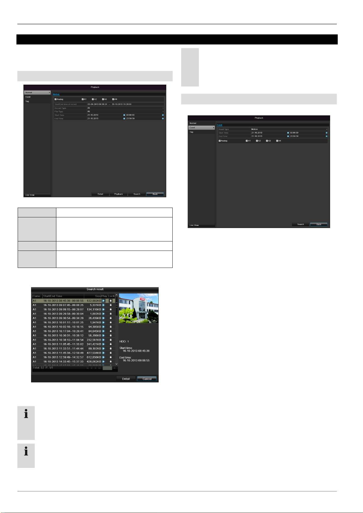
Playback
Playback
Press Configuration in the main menu and then Play-
back to search for video recordings after an event or a
marking, or to view your saved images.
Continous Recording
The following settings are available:
100
A1 - A4
Camera to be set
Record Type
Schedule, motion detection, alarm or mo-
tion detection and/or alarm, manual re-
cording, all
File Type
Locked, unlocked, all
Start Time
End Time
Enter the date and time
Click on Search to search for recordings with the cor-
responding settings. The results are then shown:
Select the recording by clicking on the line and then
on “Play”-symbol.
Note
You can return to events search at any time in the
playback mode by performing a right click and se-
lecting ‘Video Search’.
Note
The sub-menus ‘Tag’ and ‘Picture’ are almost iden-
tical with the menu described above and are there-
fore not listed separately.
In the sub-menu ‘Tag’, searching does not take
place according to recording type, rather according
to identification or a keyword of the markings’
name
Event
Please klick on the TAB „Event“.
A list of all event types is displayed.
For “Event Type” select whether a search is to be made
for recordings with motion (motion detection).
Select one or more cameras by activating the checkbox.
Click on Search.
Select one or more event markings from the list which
appears. Click on Details to obtain more information
about the recordings.
