Stiebel Eltron PSH Universal EL с 05.12.2011: inStallation
inStallation: Stiebel Eltron PSH Universal EL с 05.12.2011
En
gl
ish
www.Stiebel-eltron.CoM
PSH UniverSal el|
27
inStallation
Safety
inStallation
7. safety
Only a qualified contractor should carry out installation, commis-
sioning, maintenance and repair of the appliance.
7.1 general safety instructions
We guarantee trouble-free operation and operational reliability
only if the original accessories and spare parts intended for the
appliance are used.
7.2 instructions, standards and regulations
Note
Observe all applicable national and regional regulations
and instructions.
8. appliance description
8.1 standard delivery
Delivered with the appliance:
- 2 fitted wall mounting brackets
- Safety valve (SYR) with non-return valve
9. Preparations
9.1 installation site
The appliance is designed for installation on a solid wall. Ensure
the wall offers adequate load bearing capacity.
There should be a suitable drain near the appliance to drain off
the expansion water.
26
�0
2�
09
�0
13
5
f
f
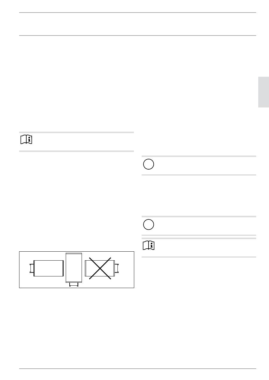
Install the appliance vertically or horizontally as shown in a
room free from the risk of frost and near the draw-off point.
10. Preparing for installation
10.1 Preparing to install the appliance
The wall mounting brackets attached to the appliance have hook-
in slots, which in most cases enable installation on the bolts that
are already in place from previous appliances.
f
f
Otherwise, transfer the dimensions for the holes to be drilled
on the wall (see chapter "Specification / Dimensions and
connections").
f
f
Drill the holes, if required, and secure the wall mounting
brackets with screws and rawl plugs. Select fixing materials
in accordance with the wall construction/condition.
f
f
Hook the appliance with wall mounting brackets on to the
screws or bolts. Observe the weight of the appliance when
empty (see chapter "Specification / Data table") and, if neces-
sary, ask another person to help.
f
f
Align the appliance vertically or horizontally.
10.2 water connection
!
Damage to the appliance and environment
Make all water connection and installation work in ac-
cordance with regulations.
cold water line
Steel or copper pipes or plastic pipework are approved materials.
dHw line
Copper or plastic pipework are approved materials.
!
Damage to the appliance and environment
When using plastic pipework, observe chapter "Specifica-
tion / Fault conditions".
Note
If the water pressure is higher than 0.6 MPa, install a
pressure reducer in the "cold water inlet".
Operate the appliance only with pressure-tested taps.
f
f
Thoroughly flush out the cold water line before connecting
the appliance, so that no foreign matter gets into the water
heater or safety valve.
f
f
Route the safety valve drain line to a drain free from the risk
of frost, with a continuous downward slope to ensure the un-
restricted flow of the water to the drain. The discharge aper-
ture of the safety valve must remain open to the atmosphere.
28
| PSH UniverSal el www.Stiebel-eltron.CoM
inStallation
PreParing for inStallation
10.3 electrical connection
DANGER Electrocution
Before any work on the appliance, disconnect all poles
of the appliance from the power supply.
DANGER Electrocution
Carry out all electrical connection and installation work
in accordance with relevant regulations.
DANGER Electrocution
Only use a permanent connection to the power supply.
The appliance must be able to be separated from the
power supply by an isolator that disconnects all poles
with at least 3 mm contact separation.
Note
Observe the type plate. The specified voltage must match
the mains voltage.
Note
Please note that the appliance must be connected to the
earth conductor.
1
2
3
26
�0
2�
07
�0
28
6
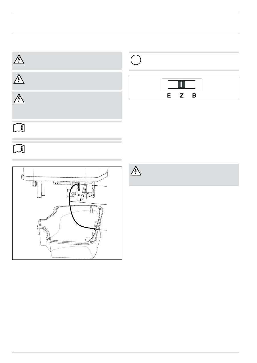
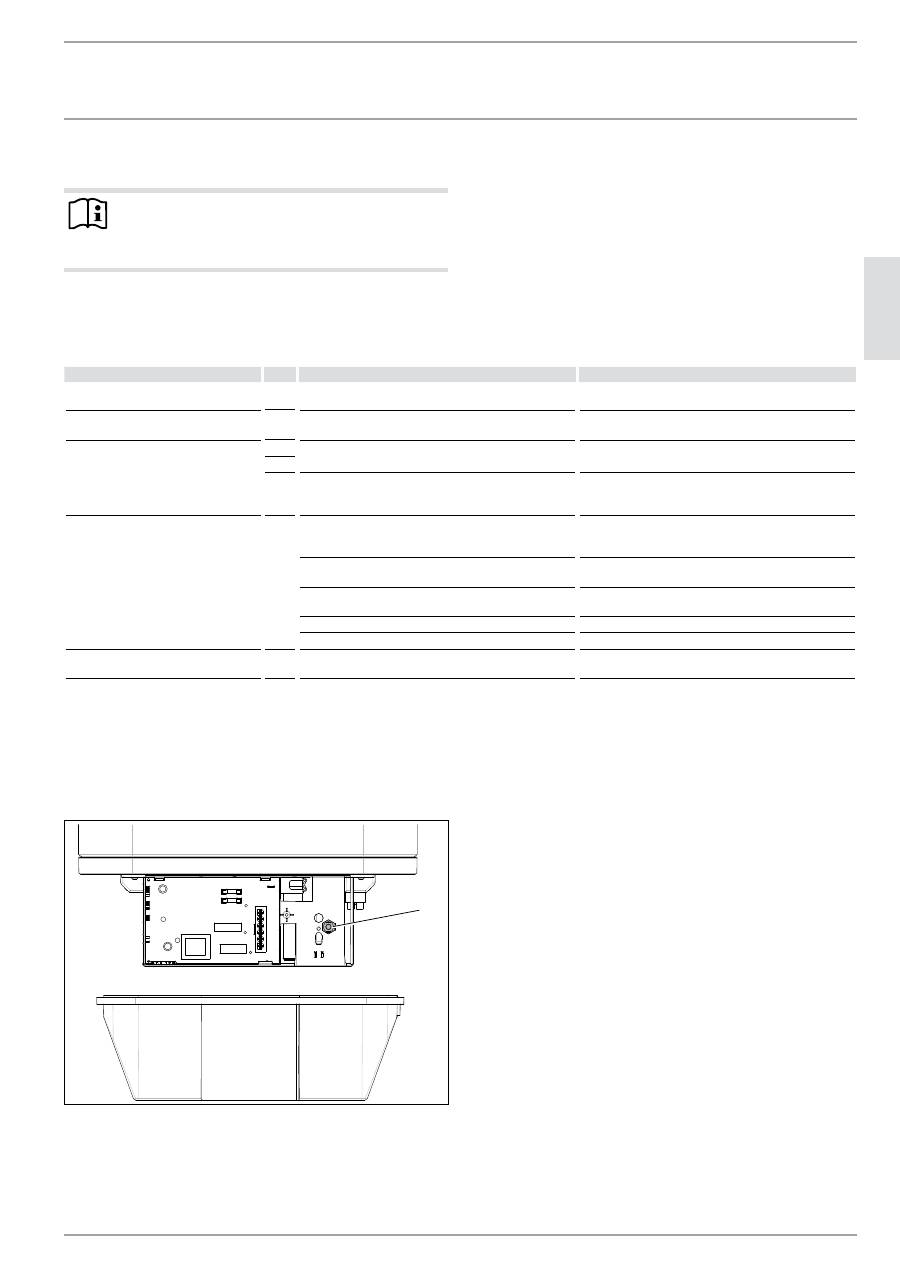
1 Electronic assembly, control unit, position X2
2 Connecting cable, electronic assemblies
3 Electronic assembly, operation
removing the lower cover
f
f
Undo the 4 screws.
f
f
Remove the bottom cap.
f
f
Disconnect the connecting cable from the electronic assem-
bly for operation, position X2.
Also in dual circuit operation:
f
f
Pull out the cable grommet at the base while pressing the
snap-in tabs.
f
f
Push the cable grommet over the power cable and snap the
cable grommet back in place.
selecting the operating mode
!
Damage to the appliance and environment
Only change the operating mode when isolated from the
power supply.
26
�0
2�
07
�0
28
5
E Single circuit operation
Z Dual circuit operation
B Manual operation
f
f
Select the operating mode with the switch on the control unit
electronic assembly and select the required connection (see
chapter "Specification / Wiring diagrams and connections").
f
f
Plug the connecting cable into the electronic assembly, posi-
tion X2 (see chapter "Specification / Wiring diagrams and
connections").
f
f
Secure the bottom cap with the 4 screws.
Power cable
DANGER Electrocution
The power cable must only be replaced (for example if
damaged) by contractors authorised by the manufac-
turer.
The appliance is supplied with a flexible power cable with wire
ferrules and without plug, ready to connect.
f
f
If the cable is of insufficient length, unclamp it from the ap-
pliance. Use a suitable installation cable.
f
f
When routing the new power cable, ensure that it is water-
proof as it passes through the existing cable grommet, and is
correctly routed and connected inside the appliance.
En
gl
ish
www.Stiebel-eltron.CoM
PSH UniverSal el|
29
inStallation
CoMMiSSioning
11. commissioning
11.1 commissioning
f
f
Open the shut-off valve in the cold water line.
f
f
Open a draw-off point until the appliance has filled up and
the pipework is free of air.
f
f
Observe the maximum permissible flow rate with a fully
opened tap (see chapter "Specification / Data table").
f
f
Switch the mains power ON. The appliance carries out a
self-test.
f
f
Check the function of the appliance.
f
f
Check the function of the safety valve.
11.1.1 appliance handover
f
f
Explain the appliance function to users and familiarise them
with its operation.
f
f
Show the user the safety valve and its operating instructions,
and explain its significance.
f
f
Make the user aware of potential dangers, especially the risk
of scalding.
f
f
Hand over these instructions.
11.2 returning into use
See chapter "Commissioning".
12. settings
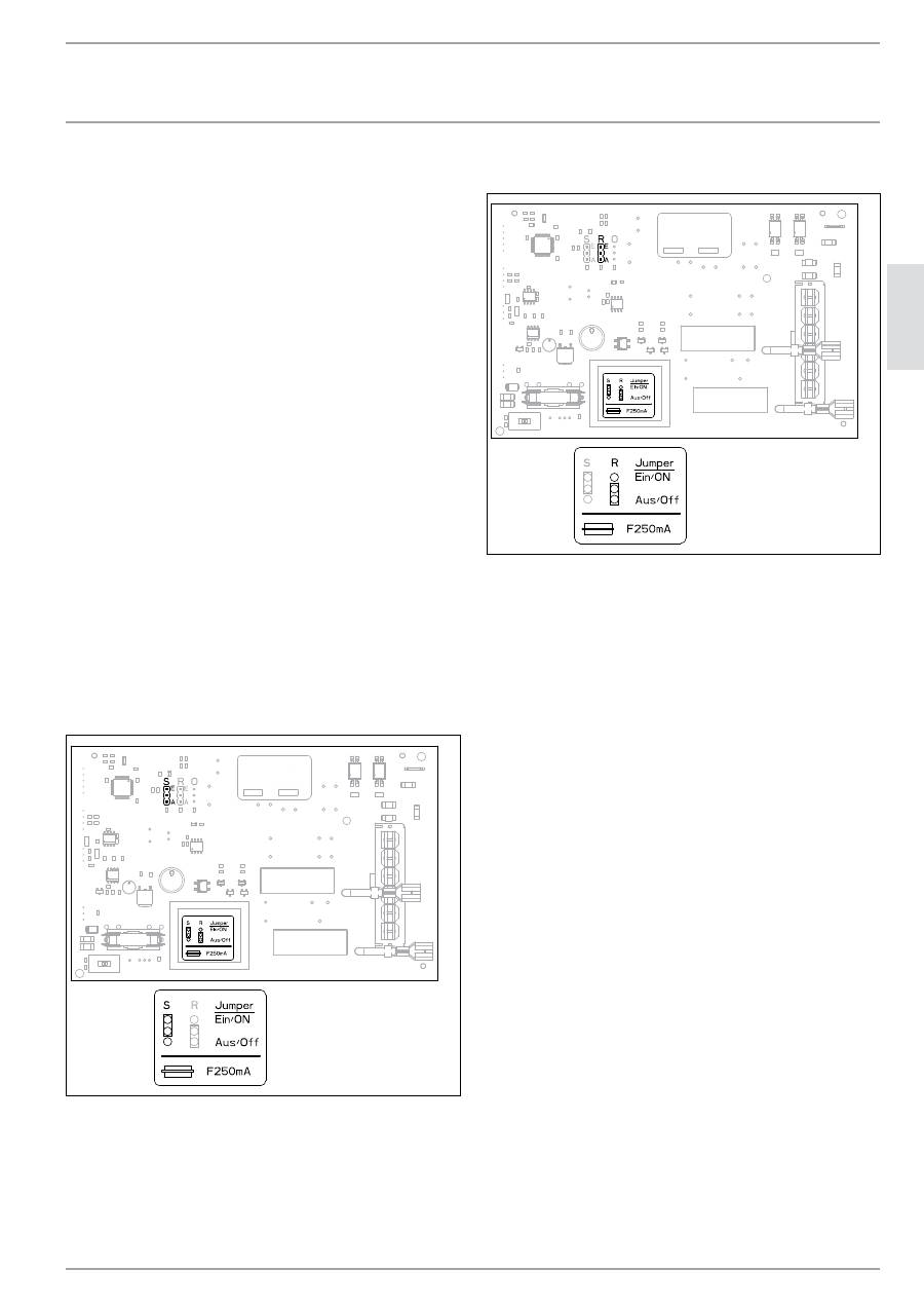
12.1 switching on commercial mode
26
�0
2�
07
�0
29
6
S Jumper ECO (energy saving mode)
E ECO ON (factory setting)
A ECO OFF (commercial mode)
f
f
To switch on commercial mode, replug the jumper.
12.2 switching on reverse control
26
�0
2�
07
�0
29
6
R Reverse control jumper
E Reverse control ON
A Reverse control OFF (factory setting)
f
f
To switch on reverse control, replug the jumper.
13. taking the appliance out of use
f
f
Disconnect the appliance from the mains at the MCB/fuse in
the fuse box.
f
f
Drain the appliance. See chapter "Maintenance / Draining the
appliance".
30
| PSH UniverSal el www.Stiebel-eltron.CoM
inStallation
MaintenanCe
14. maintenance
DANGER Electrocution
Before any work on the appliance, disconnect all poles
of the appliance from the power supply.
DANGER Electrocution
Carry out all electrical connection and installation work
in accordance with relevant regulations.
If you additionally need to drain the appliance, observe chapter
"Draining the appliance".
14.1 checking the safety assembly and safety valve
f
f
Check the safety assembly and safety valve regularly.
14.2 draining the appliance
DANGER Scalding
Hot water may escape during the draining process.
If the appliance needs to be drained for maintenance or to protect
the whole installation when there is a risk of frost, proceed as
follows:
f
f
Close the shut-off valve in the cold water line.
f
f
Open the hot water taps on all draw-off points.
26
�0
2�
07
�0
28
8
1
1 Drain valve cap
f
f
Undo the cap of the drain valve.
14.3 checking the protective anode
f
f
Check the protective anode after the first year of use and re-
place if necessary.
f
f
Afterwards determine the time intervals at which further
checks should be carried out.
14.4 descaling
f
f
Remove loose scale deposits from the water heater.
f
f
If necessary, descale the inner cylinder with commercially
available descaling agents.
f
f
Only descale the flange after disassembly and never treat the
cylinder surface and protective anode with descaling agents.
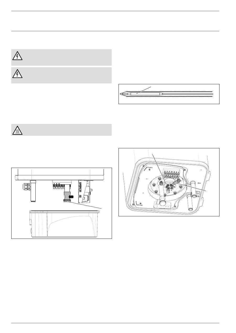
14.5 installing the temperature limiter
26
�0
2�
07
�0
30
5
1
1 Limiter sensor
f
f
Insert the limiter sensor into the sensor well as far as it will
go.
14.6 replacing the heating element
The heating element is located inside a protective pipe. This ena-
bles a "dry" replacement of the heating element. The appliance
does not need to be drained when replacing the heating elements.
2
1
26
�0
2�
07
�0
30
6
1 Ceramic heating element in protective enamelled pipe
2 Heating element fixture
En
gl
ish
www.Stiebel-eltron.CoM
PSH UniverSal el|
31
inStallation
troUbleSHooting
15. troubleshooting
Note
The high limit safety cut-out can respond at temperatures
below –15 °C. The appliance may be subjected to these
temperatures during storage or transport.
f
f
Display the fault code (see chapter "Settings / Displaying the
fault code").
f
f
The plugs are described in chapter "Specification / Wiring
diagrams and connections".
fault
Code Cause
f
f
remedy
The heat-up time is very long and the
heat-up symbol lights up.
The flanged immersion heater is scaled up.
Descale the flanged immersion heater.
The safety valve is dripping and the
heat-up symbol does not light up.
The valve seat is contaminated.
Clean the valve seat.
The display flashes.
E2
The temperature sensor is faulty.
Check whether plug X10 is properly inserted.
E4
Check the temperature sensor.
E128
Communication between the electronic assemblies for
control unit and operation is faulty.
Check whether plugs X2 are inserted properly in both
assemblies. Check the assemblies and the connecting
cable.
The water does not heat up.
The heat-up symbol does not appear.
The display flashes.
E8
The high limit safety cut-out has responded.
Check the appliance and eliminate the cause. Press the
reset button (see diagram).
The high limit safety cut-out has responded because the
thermostat is faulty.
Remedy the cause of the fault. Replace the high limit
safety cut-out.
The high limit safety cut-out has responded because the
temperature has dropped below -15 °C.
Press the reset button (see diagram).
The booster heater does not switch on.
Check the button.
The flanged immersion heater is faulty.
Replace the flanged immersion heater.
The water does not heat up.
The display flashes.
E6
The temperature sensor is faulty.
Check whether plug X10 is properly inserted.
Check the temperature sensor.
reset button, high limit safety cut-out
f
f
Isolate the appliance from the power supply.
f
f
Undo the screws and remove the bottom cap.
f
f
Disconnect the connecting cable from the electronic assem-
bly for operation, position X2.
1
26
�0
2�
07
�0
28
7
1 High limit safety cut-out reset button
32
| PSH UniverSal el www.Stiebel-eltron.CoM
inStallation
SPeCifiCation
16. specification
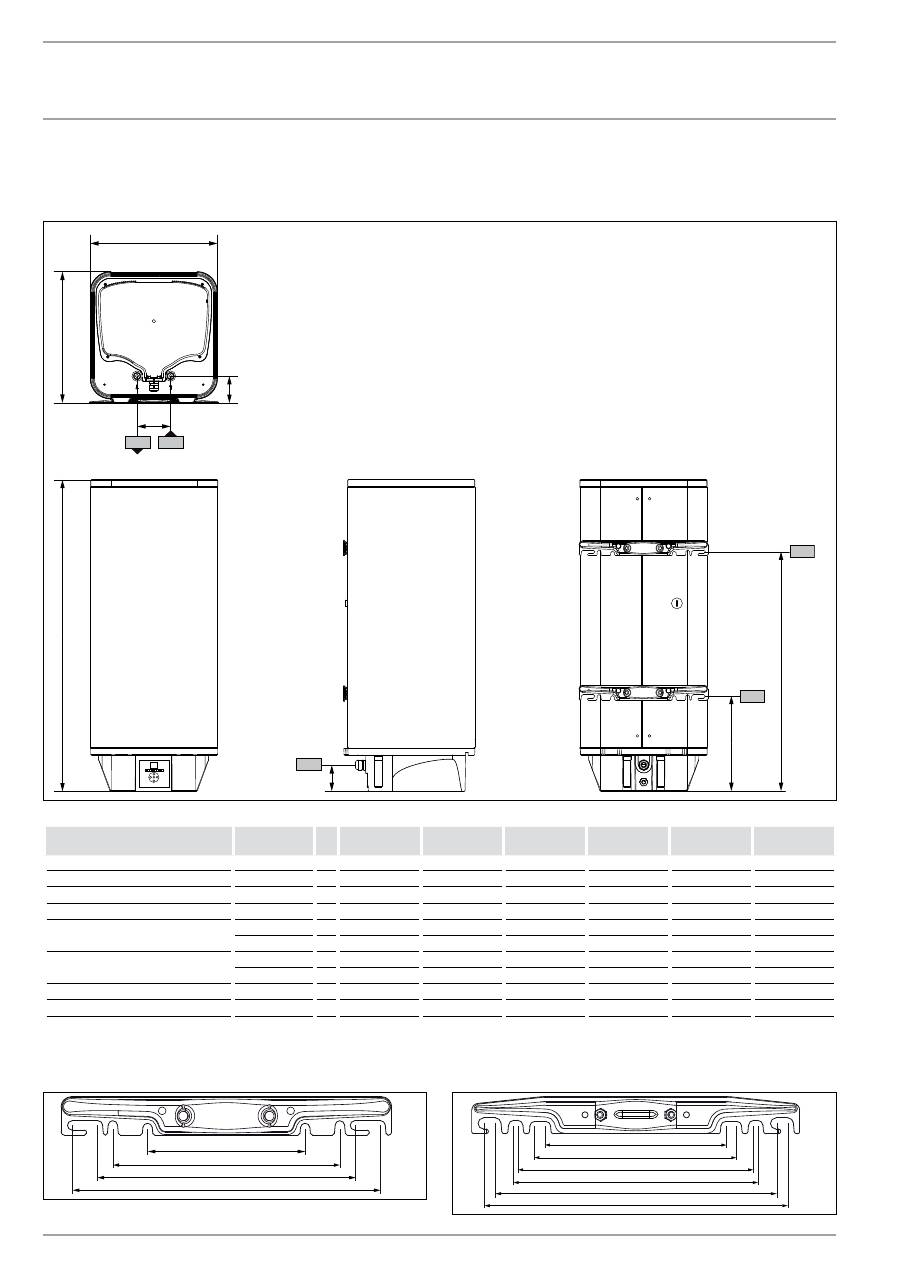
16.1 dimensions and connections
100
a20
a30
a10
c01
c06
b01
i14
i15
D
00000
18
70
5
PSH 30
Universal el
PSH 50
Universal el
PSH 80
Universal el
PSH 100
Universal el
PSH 120
Universal el
PSH 150
Universal el
a10 Appliance
Height
mm
676
931
893
1045
1200
1435
a20 Appliance
Width
mm
380
380
475
475
475
475
a30 Appliance
Depth
mm
380
380
475
475
475
475
b01 Entry electrical cables
Height
mm
78.5
78.5
78.5
78.5
78.5
78.5
c01 Cold water inlet
Male thread
G ½ A
G ½ A
G ½ A
G ½ A
G ½ A
G ½ A
Rear clearance mm
80
80
85
85
85
85
c06 DHW outlet
Male thread
G ½ A
G ½ A
G ½ A
G ½ A
G ½ A
G ½ A
Rear clearance mm
80
80
85
85
85
85
i14 Wall mounting bracket 1
Height
mm
445
705
592
735
870
1090
i15 Wall mounting bracket 2
Height
mm
210
270
270
300
300
300
wall mounting bracket
30 - 50 l
184
265
300
360
80
�0
2�
07
�0
00
5
80 - 150 l
450
415
360
350
300
265
80
�0
2�
07
�0
00
6
En
gl
ish
www.Stiebel-eltron.CoM
PSH UniverSal el|
33
inStallation
SPeCifiCation
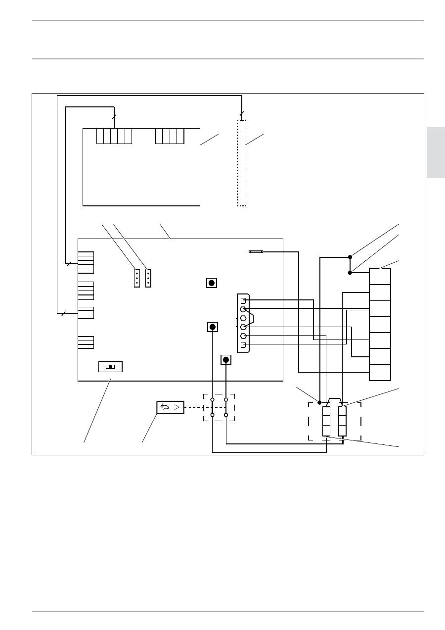
16.2 wiring diagrams and connections
FB
L1
CB
L3
N
L2
L1
L3
N
L2
PE
5
6
LF
X6
ws
vi
S
E Z B
X2
X12
X10
X7
A
E
A
E
X2
X1
5
5
3
3
X9
R
3
1
12
13
2
5
6
7
9 10
11
8
85
�0
2�
07
�0
02
3
4
1 Anode
2 Water heater
3 Mains terminal
4 Ceramic heating element in protective enamelled pipe
5 Heating output
PSH 30 Universal EL: 1.6 kW ~ 230 V
PSH 50-150 Universal EL: 2 kW ~ 230 V
6 Additional heating output, 1 kW ~ 230 V
7 High limit safety cut-out
8 Operating mode switch
9 Jumper ECO
10 Reverse control jumper
11 Electronic assembly, control unit
12 Electronic assembly, operation
13 Temperature sensor
34
| PSH UniverSal el www.Stiebel-eltron.CoM
inStallation
SPeCifiCation
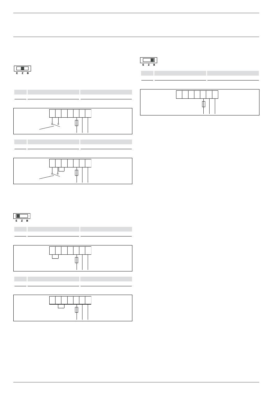
16.2.1 dual circuit operation
The output from rapid heating is shown after the forward slash.
single meter measurement with eVu contact
PSH 30 Universal el
PSH 50-150 Universal el
kW
1.6 / 2.6
2 / 3
L1
L3
N
L2
PE
5
6
85
�0
2�
07
�0
02
0
1
PSH 30 Universal el
PSH 50-150 Universal el
kW
2.6 / 2.6
3 / 3
L1
L3
N
L2
PE
5
6
85
�0
2�
07
�0
02
1
1
1 Power-OFF contact
16.2.2 single circuit operation
The output from rapid heating is shown after the forward slash.
PSH 30 Universal el
PSH 50-150 Universal el
kW
1.6 / 2.6
2 / 3
L1
L3
N
L2
PE
5
6
85
�0
2�
07
�0
01
8
PSH 30 Universal el
PSH 50-150 Universal el
kW
2.6 / 2.6
3 / 3
L1
L3
N
L2
PE
5
6
85
�0
2�
07
�0
01
9
16.2.3 manual operation
PSH 30 Universal el
PSH 50-150 Universal el
kW
2.6
3
L1
L3
N
L2
PE
5
6
85
�0
2�
07
�0
02
4
16.3 Fault conditions
In the event of a fault, temperatures of up to 95 °C at 0.6 MPa
can occur.
En
gl
ish
www.Stiebel-eltron.CoM
PSH UniverSal el|
35
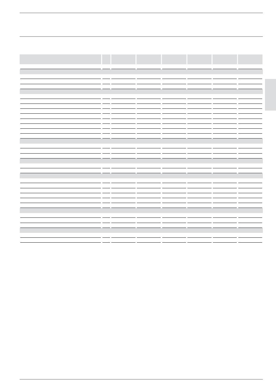
16.4 data table
PSH 30
Universal el
PSH 50
Universal el
PSH 80
Universal el
PSH 100
Universal el
PSH 120
Universal el
PSH 150
Universal el
231150
231151
231152
231153
231649
231154
Hydraulic data
Nominal capacity
l
30
50
80
100
120
150
Mixed water volume 40 °C (15 °C/60 °C), vertical
l
53
92
136
183
217
273
Mixed water volume 40 °C (15 °C/60 °C), horizontal
l
42
76
111
153
173
194
Electrical data
Connected load ~ 230 V
kW
2.6
3
3
3
3
3
Rated voltage
V
230
230
230
230
230
230
Phases
1/N/PE
1/N/PE
1/N/PE
1/N/PE
1/N/PE
1/N/PE
Frequency
Hz
50
50
50
50
50
50
Single circuit operating mode
X
X
X
X
X
X
Dual circuit operating mode
X
X
X
X
X
X
Manual operating mode
X
X
X
X
X
X
Heat-up time 2.6 kW (15 °C/60 °C)
h
0.61
Heat-up time 3.0 kW (15 °C/60 °C)
h
0.88
1.42
1.77
2.13
2.66
Application limits
Temperature setting range
°C
7-85
7-85
7-85
7-85
7-85
7-85
Max. permissible pressure
MPa
0.6
0.6
0.6
0.6
0.6
0.6
Max. flow rate
l/min
23.5
23.5
23.5
23.5
23.5
23.5
Energy data
Standby energy consumption/24 h at 65 °C, vertical
kWh
0.57
0.78
0.88
1.05
1.19
1.29
Standby energy consumption/24 h at 65 °C, horizontal kWh
0.83
0.94
1
1.26
1.43
1.57
Versions
IP rating vertical
IP25
IP25
IP25
IP25
IP25
IP25
IP rating horizontal
IP24
IP24
IP24
IP24
IP24
IP24
Sealed unvented type
X
X
X
X
X
X
Power cable
X
X
X
X
X
X
Power cable length
mm
1000
1000
1000
1000
1000
1000
Colour
white
white
white
white
white
white
Dimensions
Height
mm
676
931
893
1045
1200
1435
Width
mm
380
380
475
475
475
475
Depth
mm
380
380
475
475
475
475
Weight
Weight (full)
kg
52
78
114
138
163
202
Weight (empty)
kg
22
28
34
38
43
52
inStallation | warranty | environMent and reCyCling
SPeCifiCation
warranty
environMent and reCyCling
Warranty
The warranty conditions of our German companies do not
apply to appliances acquired outside of Germany. In countries
where our subsidiaries sell our products, it is increasingly the
case that warranties can only be issued by those subsidiaries.
Such warranties are only granted if the subsidiary has issued
its own terms of warranty. No other warranty will be granted.
We shall not provide any warranty for appliances acquired in
countries where we have no subsidiary to sell our products.
This will not affect warranties issued by any importers.
Environment and recycling
We would ask you to help protect the environment. After use,
dispose of the various materials in accordance with national
regulations.
