Eneo NXD-980IR3516P: DE EN FR PL RU
DE EN FR PL RU: Eneo NXD-980IR3516P
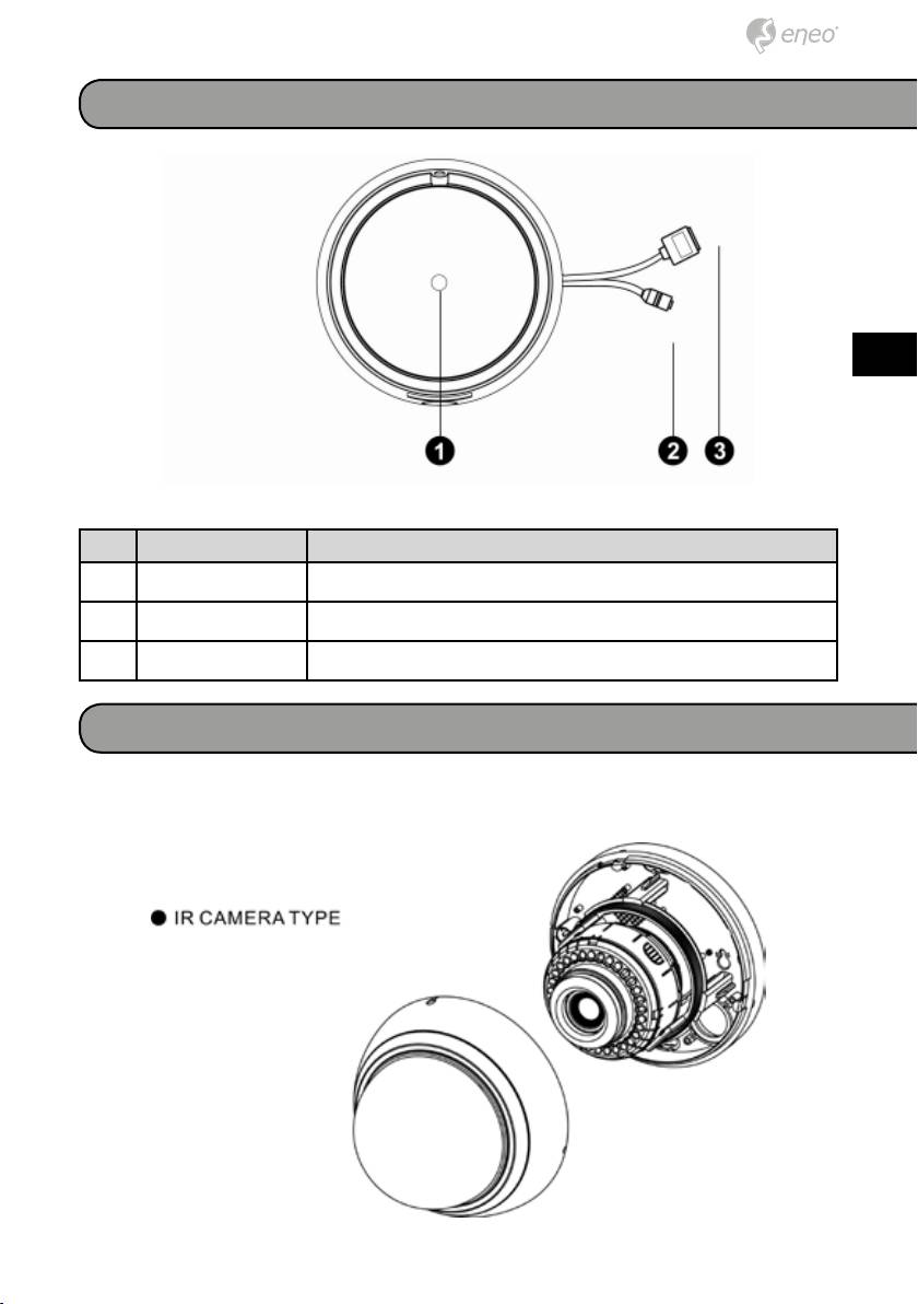
Connections
DE
EN
FR
PL
RU
NO Name Description
1 Lens Allows wide area to be monitored
2 Power Cable Cable for Power source (DC 12V)
3 Ethernet Cable Cable for Ethernet (PoE)
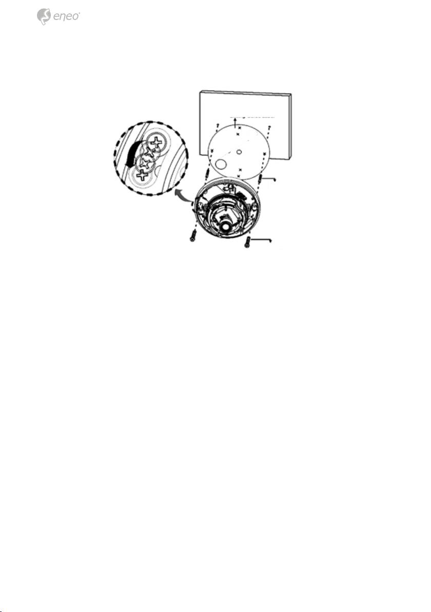
Installation
1. Make mounting holes and cable hole in the place (ceiling or wall) to
which this dome camera is installed using the Drilling Guide label.
15
2. To remove dome cover, turn the dome body counterclockwise until loca-
tors reach end of travel and pull off. Push the liner on the sides where
the patterns are put in the teeth of a comb and pull it out.
Ceiling/Wall
Drilling Guide Label
Drilling Position
Plastic anchor
Screw Tapping (M6)
3. Attach the housing to the ceiling using suitable fasteners, M6x35 tap-
ping screws are supplied only use if they are suitable. Turn the housing
to right direction about 16 degrees to lock in place.
4. The assembly of the dome body and liner is in reverse order of disas-
sembly. Finally, lock dome body with locking screw (M3x5) from the
accessory kit.
16
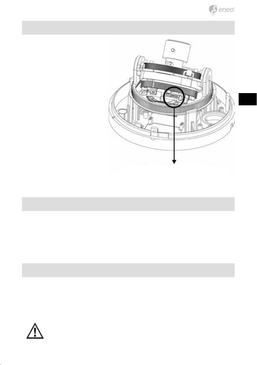
microSD card slot
Insert the microSD card.
DE
EN
FR
PL
RU
microSD card
Connecting the Power
Connect the DC 12V power adaptor to the camera.
Network Connection and IP assignment
The Network Camera supports the operation through the network. When
a camera is first connected to the network it has no assigned IP address.
So, it is necessary to allocate an IP address to the device with the “eneo
Scan Device” tool found on the supplied CD. The factory default IP is
“192.168.1.10”
NOTE: For more information, refer to the eneo Scan Device tool
Manual.
17
Operation
The Network Camera can be used with Windows operating system and
browsers. The recommended browsers are Internet Explorer, Safari, Firefox,
Opera and Google Chrome with Windows.
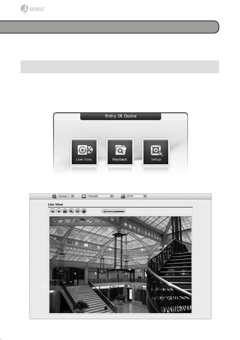
Access from a browser
1. Start a browser. (Internet Explorer) will be used in this example.
2. Enter the IP address or host name of the Network Camera in the Loca-
tion/Address field of your browser.
3. You can see a starting page. Click Live View or Setup to enter web
page.
4. The network camera’s Live View page appears in your browser.
18
Оглавление
- DE EN FR PL RU
- DE DE EN EN
- DE DE
- DE DE EN EN FR FR PL PL RU RU
- DE
- DE EN FR PL RU
- DE EN
- DE EN FR PL RU
- DE DE EN EN FR FR PL PL RU RU
- DE DE
- DE DE EN EN FR FR PL PL RU RU
- DE DE
- DE DE EN EN FR FR PL PL RU RU
- DE DE
- DE DE EN EN FR FR PL PL RU RU
- DE DE EN EN
- DE DE
- DE DE EN EN FR FR PL PL RU RU
- DE DE
- DE DE EN EN FR FR PL PL RU RU
