Benelli M4 Tactical Shotgun – страница 6
Инструкция к Benelli M4 Tactical Shotgun
100
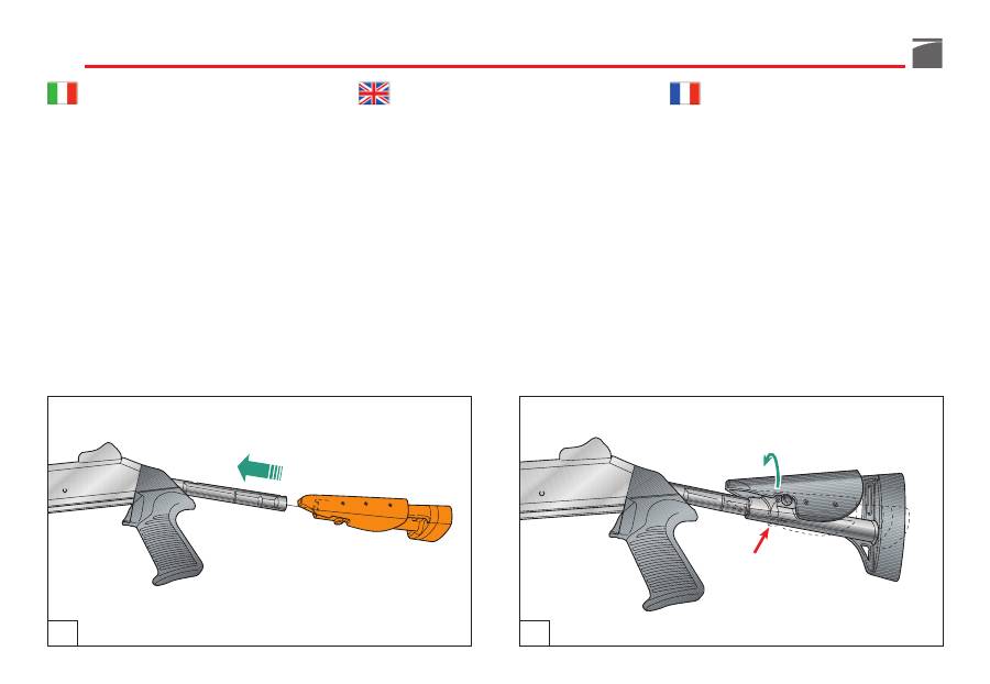
3) Montare
il calcio telescopico
(figg. 55-
56), effettuando in senso contrario la
sequenza delle operazioni descritte nella
fase di smontaggio.
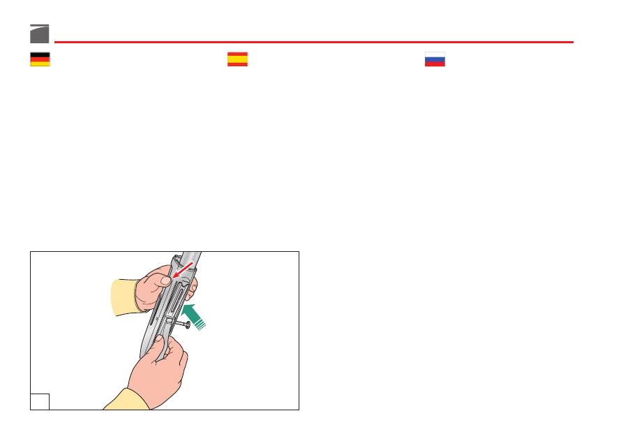
4) Impugnare il gruppo
calcio-carcassa
al-
l'altezza della carcassa e premere
il bot-
tone
comando elevatore, inserendo con-
temporaneamente
il gruppo guardia
com-
pleto -
a cane armato
- nella carcassa, in
posizione leggermente avanzata, arretran-
dolo poi
fino alla battuta
sul retro della
carcassa stessa (fig. 57).
3) Install
the telescoping stock
(figs. 55-56),
following in the reverse sequence of
which it was disassembled.
4) Lift the
stock-receiver
group as far as
the
receiver
and press
the carrier button
,
insert
the complete trigger group
-
with
cocked hammer
- on the receiver in
slightly forward position, then draw it
back
until engaged
in the rear of the
receiver itself (fig. 57).
3) Monter
la crosse télescopique
(fig. 55-56)
en effectuant en sens contraire la séquen-
ce d’opérations décrites pour la phase de
démontage.
4) Empoigner le groupe
crosse-carcasse
à
hauteur de la carcasse et presser le
bou-
ton
de commande élévateur en introdui-
sant simultanément
la sous-garde
com-
plète – avec le
chien armé
– dans la car-
casse en le positionnant légèrement en
avant, avant de le ramener vers l’arrière
jusqu’à butée
sur l’arrière de la carcasse
elle-même (fig. 57).
55
56
101
3) Den
Teleskopschaft
(Abb. 55-56) ein-
bauen; dafür die für das Zerlegen aus-
geführten Handgriffe in umgekehrter Rei-
henfolge wiederholen.
4) Die
Baugruppe Schaft und Gehäuse
senk-
recht stellen, das Gehäuse umgreifen und
gleichzeitig den
Verschlussfangknopf
drücken. Währenddessen muss die
kom-
plette Abzugsgruppe -bei gespanntem
Hahn-
leicht nach vorn versetzt in das
Gehäuse eingeführt und bis
zum Anschlag
im Heck des Gehäuses gezogen werden
(Abb. 57).
3) Monte
la culata telescópica
(figs. 55-56),
efectuando en sentido contrario la se-
cuencia de las operaciones descritas en la
fase de desmontaje.
4) Coja el grupo
culata-carcasa
a la altura
de la carcasa y pulse
el botón
de mando
del elevador introduciendo al mismo
tiempo el
grupo guardamonte
completo,
con el
martillo armado
, en la carcasa, en
posición ligeramente avanzada; haga
retroceder un poco todo el grupo guarda-
monte
hasta el tope
en la parte posterior
de la misma carcasa (fig. 57).
3) Монтировать
телескопический приклад
(рис. 55-56), выполнив в обратной
последовательности операции, описанные
на этапе демонтажа.
4) Взять узел
приклада -ствольной коробки
на высоте ствольной коробки и нажать на
кнопку
управления
держателем,
одновременно вставив укомплектованный
узел предохранительной скобы – со
взведенным курком
- в ствольную
коробку, в выдвинутое слегка вперед
положение, отведя затем назад
до упора
на задней части ствольной коробки (рис.
57).
57
102
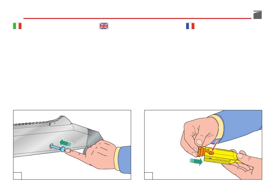
5) Bloccare il gruppo guardia con l’apposita
spina
(fig. 58).
6) Infilare
la testa di chiusura
nell'otturato-
re, facendo collimare
il foro
sul suo gam-
bo con
l'asola
dell'otturatore stesso (fig.
59).
7) Infilare
il perno
di rotazione testa di chiu-
sura nella propria sede sulla testa, facen-
dolo passare attraverso l'asola dell'ottura-
tore (fig. 60).
ATTENZIONE:
la linea
di riferimento marcata
sull'estremità del perno deve essere
in vista e
allineata
con l'asse longitudinale del gruppo
otturatore.
5) Block the trigger guard assembly using
the trigger guard pin
(fig. 58).
6) Insert
the bolt head
into the front of the
bolt carrier (
the hole
on its leg must be
aligned with
the slot
of the bolt) (fig. 59).
7) Insert
the locking head pin
in its hole on
the locking head’s stem, through the slot
on the bolt (fig. 60).
NOTE:
the reference line
on top of the pin
must be
visible and aligned
with the bolt
assembly longitudinal axis
5) Bloquer la sous-garde avec la
goupille
prévue (fig. 58).
6) Enfiler
la tête de fermeture
dans l’obtura-
teur en ayant soin de faire correspondre
l’orifice
sur sa tige avec la
bride
de l’ob-
turateur (fig. 59).
7) Enfiler le
goujon
de rotation de la tête de
fermeture dans son logement sur la tête
en le faisant passer à travers la bride de
l’obturateur (fig. 60).
ATTENTION
:
la ligne
de référence marquée
sur l’extrémité du pivot doit être
visible et ali-
gnée
avec l’axe longitudinal du groupe obtu-
rateur.
58
59

103
5) Den Abzugsbügel mit dem entsprechen-
den
Stift
blockieren (Abb. 58).
6) Den
Drehverschlusskopf
soweit in den
Verschluss
einschieben und ausrichten,
bis die Bohrung des Verschlusskopfes mit
dem Schlitz des Verschlusses überein-
stimmt (Abb. 59).
7) Den
Fixierbolzen
des Verschlusskopfes
durch den Schlitz des Verschlusses in die
Bohrung des Drehverschlusskopfes ein-
stecken (Abb. 60).
ACHTUNG:
Der am Zapfenende markierte
Strich
muss
sichtbar
sein und nach der
Längs-
achse
des Verschlusssatzes ausgerichtet sein.
5) Bloquee el grupo guardamonte con la
relativa
espiga
(fig. 58).
6) Introduzca
la cabeza de cierre
en el
obturador, cuidando que el
agujero
que
lleva en el vástago coincida con el
ojal
del obturador mismo (fig. 59).
7) Introduzca
el eje
de rotación de la cabeza
de cierre en el agujero de alojamiento
que se encuentra en el vástago de la
misma, pasándolo por el ojal del obtura-
dor (fig. 60).
ATENCIÓN:
la línea
de referencia marcada
en la extremidad del eje debe estar
a la vista
y alineada
con el eje longitudinal del grupo
obturador.
5) Блокировать узел предохранительной
скобы при помощи специальной
шпильки
(рис. 58).
6) Вставить
заглушку в
затвор, сделав
так, чтобы
отверстие
на его ножке
совпало с
прорезью
самого затвора
(рис. 59).
7) Вставить
штырь
вращения заглушки в
его гнездо на заглушке, пропустив его
через прорезь в затворе (рис. 60).
ВНИМАНИЕ:
справочная линия
, маркированная
на конце шпильки, должна быть
видна и
выровнена
по продольной оси узла затвора.
60
104
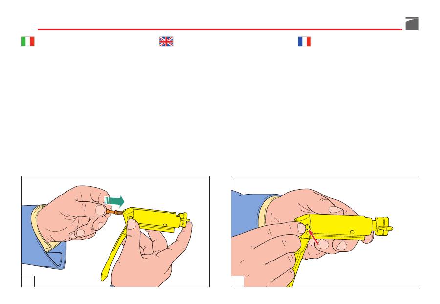
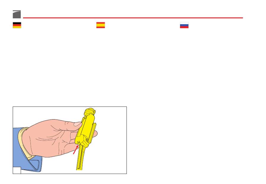
8) Infilare
il percussore completo di molla
nell'otturatore (fig. 61).
ATTENZIONE:
accertarsi di aver montato
sempre
la molla del percussore.
9) Infilare
il perno di arresto
percussore nel-
la propria sede (fig. 62).
AVVERTENZA:
se
percussore
e relativo
per-
no di arresto
sono stati montati correttamen-
te, alla fine dell'operazione il percussore si
presenterà
come illustrato
in figura 63.
8) Insert
the firing pin
and the firing pin
spring
inside the bolt (fig. 61).
NOTE:
always
make sure that the firing pin
spring has been mounted.
9) Insert
the locking pin
stud in its seat (fig.
62).
WARNING:
if
firing pin
and relative
locking
pin
have been correctly assembled, at the
end of the operation the firing pin
will appear
as described under fig. 63.
8) Enfiler le
percuteur et son ressort
dans
l’obturateur (fig. 61).
ATTENTION
:
s’assurer
toujours
d’avoir mon-
té le ressort du percuteur.
9) Enfiler le
goujon d’arrêt
du percuteur
dans son logement (fig. 62).
AVERTISSEMENT
:
si le
percuteur
et son
goujon d’arrêt
ont été correctement montés,
à la fin des opérations, le percuteur se présen-
tera
comme illustré
à la figure 63.
61
62
105
8) Den
Schlagbolzen mit Schlagbolzenfeder
von hinten in den Verschluss einsetzen
(Abb. 61).
ACHTUNG:
Stets
prüfen, ob der Schlag-
bolzen zusammen mit der Schlagbolzenfe-
der eingebaut ist.
9) Den
Schlagbolzenfixierstift
in die ent-
sprechende Bohrung einsetzen (Abb. 62).
HINWEIS:
Wenn der
Schlagbolzen
und der
entsprechende
Sperrstift
korrekt eingebaut
sind, sieht der Schlagbolzen am Ende so aus,
wie er auf der Abbildung 63
dargestellt ist
.
8) Introduzca
el percutor con su resorte
en
el agujero de alojamiento que se encuen-
tra en el obturador (fig. 61).
ATENCIÓN:
asegúrese
siempre
de haber
montado el resorte del percutor.
9) Introduzca el
eje de parada
del percutor
en su agujero de alojamiento (fig. 62).
ADVERTENCIA:
si el
percutor
y su relativo
eje de parada
han sido montados correcta-
mente, al terminar la operación el percutor se
presentará
como se muestra
en la figura 63.
8) Вставить
ударник
с его пружиной в
отверстие затвора (рис. 61).
ВНИМАНИЕ:
всегда
необходимо проверять,
что пружина установлена в ударник.
9) Вставить
стопорный штырь
бойка в его
гнездо (рис. 62).
ПРЕДУПРЕЖДЕНИЕ:
если
боек
и
соответствующий
стопорный штырь
были
монтированы правильно, в конце операции
боек будет выглядеть, как
показано
на
рисунке 63.
63
106
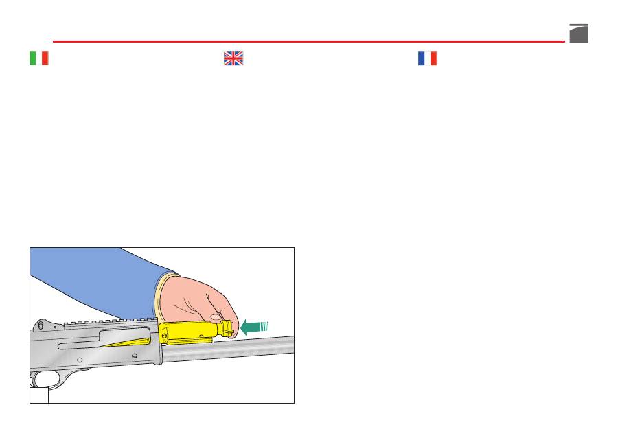
ATTENZIONE:
non
utilizzare
alcun attrezzo
per il montaggio del percussore nel corpo
otturatore:
usare solo le mani.
10) Impugnare il gruppo calcio-carcassa e,
tenendolo in posizione quasi orizzonta-
le, inserire
l'otturatore
sulle guide della
carcassa (fig. 64).
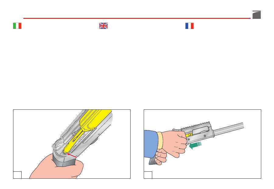
11) Infilare
la manetta
nella sede sull'ottu-
ratore,
premendola a fondo
(fig. 65).
NOTE:
do not
use
any tools
to insert the fir-
ing pin into the bolt carrier:
use fingers only.
10) Hold the stock receiver almost horizon-
tally and insert
the bolt assembly
in its
guide on the receiver (fig. 64).
11) Insert completely
the cocking lever
into
the bolt group (fig. 65).
ATTENTION
:
n’utiliser
aucun outil
pour le
montage du percuteur dans le corps de l’ob-
turateur:
utiliser seulement les mains
.
10) Empoigner le groupe crosse-carcasse et,
en le maintenant en position quasiment
horizontale, introduire
l’obturateur
dans
les guides de la carcasse (fig. 64).
11) Enfiler le
levier
dans son logement sur
l’obturateur
en le poussant à fond
(fig.
65).
64

107
ACHTUNG:
Keinerlei Werkzeug
für den Ein-
bau des Schlagbolzens in den Verschluss
benutzen, sondern
nur die Hände benutzen
.
10) Die Baugruppe Schaft und Gehäuse
nahezu horizontal halten, den
komplet-
ten Verschluss
entlang der Gehäusefüh-
rungen einschieben (Abb. 64).
11) Den
Hebel
seitlich durch die Hülsen-
auswurföffnung des Gehäuses in die
Bohrung des Verschlussblockes ein-
schieben und
fest eindrücken
(Abb.
65).
ATENCIÓN:
no
utilice
herramientas
para
montar el percutor en el cuerpo del obtura-
dor,
¡use sólo las manos!
10) Coja el grupo culata-carcasa y, mante-
niéndolo en posición casi horizontal,
introduzca el
obturador
en las correde-
ras de la carcasa (fig. 64).
11) Introduzca
la maneta
en el alojamiento
en el obturador,
apretándola a fondo
(fig. 65).
ВНИМАНИЕ:
не
использовать
никакие
инструменты
для монтажа бойка в корпус
затвора:
работать только руками.
10)
Взять узел приклада-ствольной
коробки
и,
держа
в
почти
горизонтальном положении, вставить
затвор
на направляющие ствольной
коробки (рис. 64).
11)
Вставить
рукоятку
в гнездо на
затворе,
нажав до конца
(рис. 65).
65
108
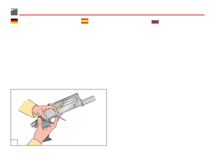
AVVERTENZA:
la biella otturatore
, passando
sopra la guardia, deve posizionarsi
nel tubo
guida molla biella, all'interno della carcassa
(fig. 66).
12) Arretrare
l’otturatore
(fig. 67).
13) Azionare
la leva discesa
cartuccia (fig.
68).
Completare il montaggio dell’arma seguendo
le istruzioni descritte a partire dal punto 4 di
pag. 46 del paragrafo “Procedura di montag-
gio”.
WARNING:
make sure that
the link
slides
over the trigger guard assembly and onto
the
recoil
spring plunger inside the receiver once
the bolt assembly is fully mounted (fig. 66).
12) Open
the bolt
(fig. 67).
13) Press
the cartridge drop lever
(fig. 68).
Complete gun reassembly by following proce-
dures listed from point 4 at page 46 “Assem-
bly procedure”.
AVERTISSEMENT
:
la bielle obturateur
, en
passant sur la garde, doit se positionner sur
le
tube
de guidage du ressort bielle à l’intérieur
de la carcasse (fig. 66).
12) Ramener
l’obturateur
vers l’arrière (fig.
67).
13) Actionner
le levier de descente
cartou-
che (fig. 68).
Terminer le montage de l’arme conformément
aux instructions données à partir du point 4
de la p. 46 du paragraphe “Opérations de
montage”.
67
66
109
HINWEIS:
Die Verbindungsstange des Ver-
schlusses
muss über dem Abzugsbügel im
Führungsrohr der Stangenfeder im Gehäuse
zu liegen kommen (Abb. 66).
12) Den
Verschluss
nach hinten ziehen
(Abb. 67).
13) Den
Patronenfreigabehebel
betätigen
(Abb. 68).
Die Montage der Waffe gemäß den Anwei-
sungen ab Punkt 4 auf Seite 47, Abschnitt
"Zusammenbauen" beenden.
ADVERTENCIA:
la biela del obturador
, pa-
sando arriba del guardamonte, debe colocar-
se en
el tubo guía del resorte
de la biela en el
interior de la carcasa (fig. 66).
12) Haga retroceder
el obturador
(fig. 67).
13) Accione
la palanca de descenso
cartu-
cho (fig. 68).
Complete el desmontaje del arma siguiendo
las instrucciones descritas a partir del punto 4
de pág. 47 del párrafo “Procedimiento de
montaje”.
ПРЕДУПРЕЖДЕНИЕ:
кулиса затвора,
пройдя над предохранительной скобой,
должна поместиться
в плунжер пружины
отдачи,
внутри ствольной коробки (рис. 66).
12)
Отвести назад
затвор
(рис. 67).
13)
Привести
в
действие
рычаг
выбрасывателя
патрона (рис. 68).
Завершить монтаж оружия, следуя
инструкциям, начиная с пункта 4 стр. 47
параграфа “Порядок монтажа”.
68
110
Inconvenienti e rimedi
Prima di effettuare qualunque tipo di inter-
vento sul fucile, accertarsi sempre che came-
ra di scoppio e serbatoio siano completa-
mente vuoti!
(Leggere attentamente le istru-
zioni di caricamento e scaricamento del-
l'arma).
Se il fucile non spara
1)
Controllare la sicura:
se inserita, spingere
il pulsante a traversino nella posizione di
fuoco (pag. 52).
2)
Controllare che la cartuccia sia in canna.
Se necessario, introdurre una cartuccia
seguendo le istruzioni relative al carica-
mento (pag. 56).
3)
Controllare il meccanismo di sparo.
Se
necessario, procedere alla sua pulizia e
lubrificazione.
Cappellotto fissaggio astine
1) Accertarsi che
il cappellotto
fissaggio
astine - specialmente dopo i primi colpi -
sia ben avvitato, in modo da mantenere
la canna
completamente
bloccata
alla
carcassa.
Il prolungamento cromato della canna
deve
essere
completamente inserito nella carcassa
e pertanto nessuna parte cromata deve essere
visibile sul fronte della carcassa stessa (fig. 9).
Troubleshooting
Before attempting any work on your M4
make sure that the chamber and the maga-
zine of your shotgun are unloaded.
(See the
instructions on loading and unloading).
The gun fails to fire:
1)
Check the safety catch:
if it is engaged,
push the button to the fire position (pag.
52).
2)
Check that there is a cartridge in the
barrel.
If necessary, insert a cartridge fol-
lowing the loading instructions (pag. 56).
3)
Check the firing mechanism.
If necessary,
clean and lubricate it.
Magazine cap
1) Especially after the first rounds, check
that
the magazine cap
is firmly tightened,
to keep
the barrel
against to the receiver.
The chrome barrel extension
must be
com-
pletely contained by the receiver. None of the
chromate parts must be visible at the front of
the receiver (fig. 9).
Problèmes et solutions
Avant toute intervention sur le fusil, contrô-
ler toujours que la chambre de déflagration
et le magasin soient entièrement vides
(lire
avec attention les instructions de chargement
et de déchargement de l’arme).
Si le fusil ne tire pas:
1)
Contrôler le cran de sûreté
: si ce dernier
est en place, pousser le bouton transver-
sal en position de tir (p. 52).
2)
Contrôler que la cartouche se trouve
dans le canon
. Si nécessaire, introduire
une cartouche en suivant les instructions
concernant le chargement (p. 56).
3)
Contrôler le mécanisme de tir
. Si néces-
saire, nettoyer et lubrifier le mécanisme.
Capuchon fixation devant
1) Contrôler que le
capuchon
de fixation
devant – en particulier après les premiers
coups – est correctement vissé et main-
tient
le canon
complètement
bloqué
à la
carcasse.
La rallonge chromée du canon
doit être
entièrement introduite dans la carcasse et au-
cune partie chromée ne doit par conséquent
être visible sur le devant de la carcasse elle-
même (fig. 9).
111
Funktionsstörungen
und Abhilfe
Vor jeglichem Handgriff an Ihrem Gewehr
sollten Sie sicherstellen, dass die Patronen-
lager und das Magazin ihres Gewehrs völlig
leer sind!
(Bitte lesen Sie aufmerksam die
Anweisungen für das Laden und das Entladen
der Waffe).
Das Gewehr schießt nicht
1)
Die Sicherung überprüfen
; falls sie akti-
viert ist, den Stegknopf auf Feuerbereits-
schaft bringen (S. 53)
.
2)
Prüfen, ob eine Patrone im Lauf ist
. Falls
nötig, unter Beachtung der Anweisungen
für das Laden (S. 57) eine Patrone ein-
stecken
.
3)
Den Schussmechanismus überprüfen
und, falls nötig, reinigen und schmieren.
Magazinrohrabschlusskappe
1) Insbesondere nach den ersten Schüssen
prüfen, ob die Magazinrohrabschlusskap-
pe gut aufgeschraubt ist, damit der
Lauf
fest am Gehäuse verankert ist
.
Der verchromte, hintere Lauffortsatz
muss
voll-
ständig in das Gehäuse eingeschoben sein; es
darf daher kein verchromtes Teil an der Gehäuse-
vorderseite sichtbar sein (Abb. 9).
Inconvenientes y soluciones
Antes de realizar cualquier tipo de opera-
ción en su fusil, asegúrese siempre que la
cámara de explosión y el almacén estén
completamente vacíos.
(Lea atentamente las
instrucciones para la carga y la descarga del
arma).
Si el fusil no dispara:
1)
Controle el seguro:
si está puesto, empuje
el botón transversal hacia la posición de
fuego (página 53).
2)
Controle que el cartucho esté en el
cañón.
Si fuera necesario, introduzca un
cartucho siguiendo las instrucciones rela-
tivas a la carga (página 57).
3)
Controle el mecanismo de disparo.
Si
fuera necesario límpielo y lubríquelo.
Capuchón fijación varillas
1) Especialmente después de los primeros
disparos, asegúrese de que el
capuchón
de fijación de la varilla esté bien atorni-
llado, para mantener el
cañón
completa-
mente
fijado
en la carcasa.
La prolongación cromada del cañón
debe
estar
completamente introducida en la carca-
sa: por lo tanto, ninguna parte cromada será
visible en la parte frontal de la carcasa (fig. 9).
Неисправности и способы
устранения
Перед тем, как выполнять любые операции
с Вашей винтовкой, убедиться, что камера
воспламенения и магазин совершенно
пустые!
(внимательно прочитать инструкции по
заряжанию и разряжанию оружия).
Если винтовка не стреляет:
1)
Проверить предохранитель:
если он
установлен, сдвинуть кнопку в виде
перекладины в положение выстрела
(стр. 53).
2)
Проверить, что патрон находится в
стволе.
Если необходимо, вставить
патрон, следуя инструкциям, относящимся
к заряжанию (стр. 57).
3)
Проверить механизм выстрела.
Если
необходимо, провести его очистку и смазку.
Заглушка крепления цевья
1) Проверить, что
заглушка
крепления
цевья – особенно после первых
выстрелов – хорошо завинчена, чтобы
поддерживать
ствол
полностью
блокированным
на ствольной коробке.
Хромированный удлинитель ствола
должен
быть
полностью вставлен в ствольную
коробку, и, поэтому, не должна быть видна ни
одна хромированная часть на передней
части ствольной коробки (рис.9).
112
Munizioni da usare
Si possono usare indistintamente cartucce
cal. 12 con bossolo da 70 mm (2" 3/4) o 76
mm (3").
ATTENZIONE
:
non usare
mai
cartucce con
bossolo
la cui lunghezza superi
quella della
camera di scoppio!
La mancata osservanza di questa regola può
comportare gravi conseguenze sia per il tira-
tore che per l'arma.
I fucili Benelli non richiedono regolazione
alcuna per qualsiasi munizionamento impie-
gato.
Tutti i fucili Benelli sono sottoposti alla pro-
va forzata di 1370 bar presso il Banco
Nazionale di Prova di Gardone Valtrompia
(Brescia).
Choice of ammunition
M4 can use 12 ga. shells with 70 mm (2" 3/4)
or 76 mm (3") cases.
CAUTION:
never
use cartridges with a case
longer than
the chamber.
Non-compliance to this rule would have
serious consequences for both the shotgun
and the shooter.
No adjustment to the shotgun is necessary to
fire any of the ammunition listed above.
All Benelli shotguns are subjected to a 1370
bar burst test at the Italian National Proof
House in Gardone Valtrompia (Brescia).
Munitions à utiliser
Il est possible d’utiliser sans distinction des
cartouches cal. 12 avec douille de 70 mm (2”
3/4) ou de 76 mm (3”).
ATTENTION
:
ne
jamais
utiliser de cartouche
d’une longueur
de douille
supérieure
à celle
de la chambre de déflagration.
Toute négligence de cette règle peut com-
porter des conséquences graves, tant pour le
tireur que pour l’arme.
Les fusils Benelli n’exigent aucun réglage,
quel que soit le type de munition employée.
Tous les fusils Benelli sont soumis à l’essai
forcé de 1370 bars auprès du Centre Natio-
nal d’Essais de Gardone Valtrompia (Brescia).

113
Zu verwendende Munition
In der M4 können sowohl Patronen des Kali-
bers 12 Gauge mit 70 mm (2" 3/4) als auch mit
76 mm (3") Hülsenlänge verwendet werden.
ACHTUNG:
Niemals
Patronen verwenden,
deren Hülsen länger als das Patronenlager der
Waffe sind!
Die Nichteinhaltung dieser Sicherheitsbe-
stimmung kann sowohl für den Schützen als
auch für die Waffe schlimme Folgen haben!
Die Benelli Selbstladeflinten M4 erfordern
keine weiteren Munitionsabstimmungen, egal
ob man nun konventionelle Patronen im Kali-
ber 12/70 oder 12/76 Magnum verwendet.
Alle Benelli-Flinten werden der Druckprü-
fung bei 1370 Bar auf dem Nationalen Prüf-
stand in Gardone Valtrompia (Brescia) unter-
zogen.
Municiones a utilizar
Pueden utilizarse indistintamente cartuchos
cal. 12 con casquillo de 70 mm (2" 3/4) o de
76 mm (3").
ATENCIÓN:
nunca
utilice cartuchos con
casquillos
cuya longitud sea superior
a la de
la cámara de explosión.
La inobservancia de esta regla comporta gra-
ves consecuencias tanto para el tirador como
para el arma.
Los fusiles Benelli no requieren ninguna regu-
lación para cualquier tipo de munición utili-
zada.
Todos los fusiles Benelli son sometidos a la
prueba forzada de 1370 bar en el Banco
Nacional de Prueba de Gardone Valtrompia
(Brescia).
Используемая амуниция
Можно использовать патроны кал. 12 с
гильзой 70 мм (2" 3/4) или 76 мм (3").
ВНИМАНИЕ:
никогда
не использовать
патроны с гильзой
с длиной, превышающей
длину камеры!
Несоблюдение данного правила может
привести к серьезным последствиям,
как для стрелка, так и для оружия.
Винтовки Benelli не требуют какого-либо
регулирования для любой используемой
амуниции.
Все винтовки Benelli проходят испытания
с усилием 1370 бар на Национальном
испытательном стенде в г. Гардоне
Валтромпия (Бреша)
.
114
ACCESSORI E REGOLAZIONI
Regolazione tacca di mira
Qualora la taratura standard effettuata in fab-
brica non risponda alle esigenze di tiro indi-
viduali, è possibile regolare la linea di mira
sia lateralmente che verticalmente.
Prima di effettuare qualunque tipo di inter-
vento sul fucile, accertarsi sempre che came-
ra di scoppio e serbatoio siano completa-
mente vuoti!
(Leggere attentamente le istru-
zioni di caricamento e scaricamento del-
l'arma).
ACCESSORIES AND SETTINGS
Rear sight adjustment
The rear sight can be adjusted for both wind-
age and elevation if the standard factory set-
ting does not meet shooter requirements.
Before attempting any work on your M4
make sure that the chamber and the maga-
zine of your shotgun are unloaded.
(See the
instructions on loading and unloading).
ACCESSOIRES ET REGLAGES
Réglage hausse
Si l’étalonnage standard effectué en usine ne
correspond pas aux exigences individuelles
de tir, il est possible de régler la ligne de mire
latéralement et verticalement.
Avant toute intervention sur le fusil, contrô-
ler toujours que la chambre de déflagration
et le magasin soient entièrement vides
(lire
avec attention les instructions de chargement
et de déchargement de l’arme).
115
ZUBEHÖR UND
EINSTELLMÖGLICHKEITEN
Visiereinstellung
Falls die im Werk erfolgte Einstellung nicht
den persönlichen Visiergewohnheiten ent-
spricht, kann die Visierung sowohl seitlich als
auch in der Höhe justiert werden.
Vor jeglichem Handgriff an Ihrem Gewehr
sollten Sie sicherstellen, dass die Patronen-
lager und das Magazin ihres Gewehrs völlig
leer sind!
(Bitte lesen Sie aufmerksam die
Anweisungen für das Laden und das Entladen
der Waffe).
ACCESORIOS Y AJUSTES
Ajuste alza
En caso de que el ajuste estándar realizado
en la fábrica no corresponda con las exigen-
cias de tiro individuales, es posible ajustar la
línea de punteria tanto lateral como vertical-
mente.
Antes de realizar cualquier tipo de opera-
ción en su fusil, asegúrese siempre que la
cámara de explosión y el almacén estén
completamente vacíos.
(Lea atentamente las
instrucciones para la carga y la descarga del
arma).
Принадлежности и
регулирования
Регулирование целика
Если
стандартная
калибровка,
произведенная на заводе, не соответствует
индивидуальным требованиям выстрела,
возможно отрегулировать линию прицела
как по горизонтали, так и вертикально.
Перед тем, как выполнять любые операции
с Вашей винтовкой, убедиться, что камера
воспламенения и магазин совершенно
пустые!
(внимательно прочитать инструкции по
заряжанию и разряжанию оружия).
116
Regolazione laterale
linea di mira
Per la regolazione laterale della linea di mira,
prevista
sulla tacca di mira
, operare come
segue:
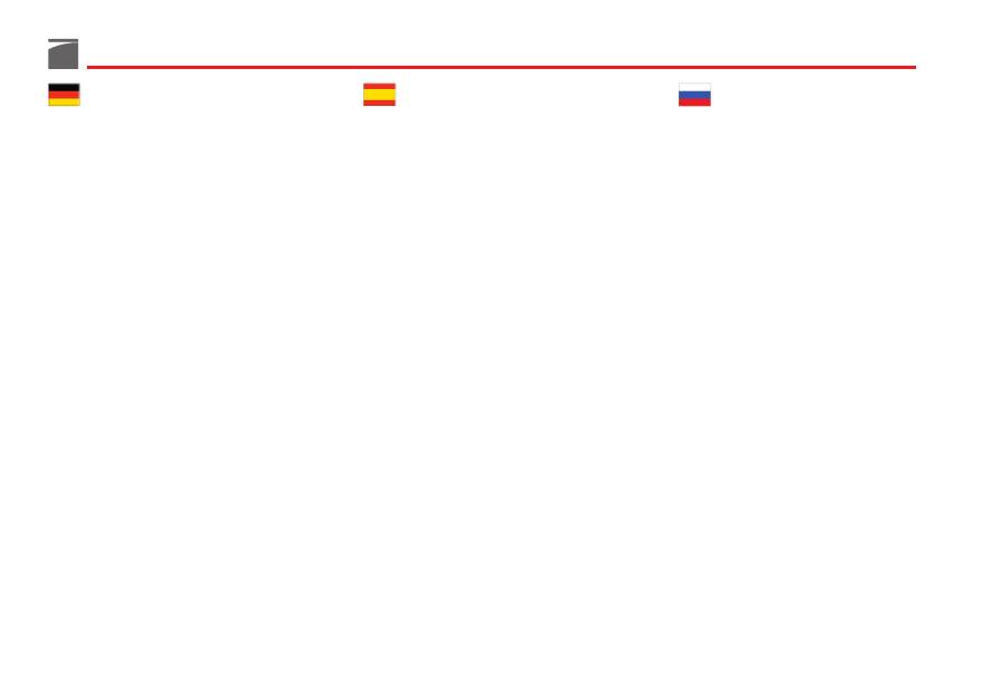
Agendo con una moneta o con il fondello di
una cartuccia,
sulla apposita vite
(fig. 69),
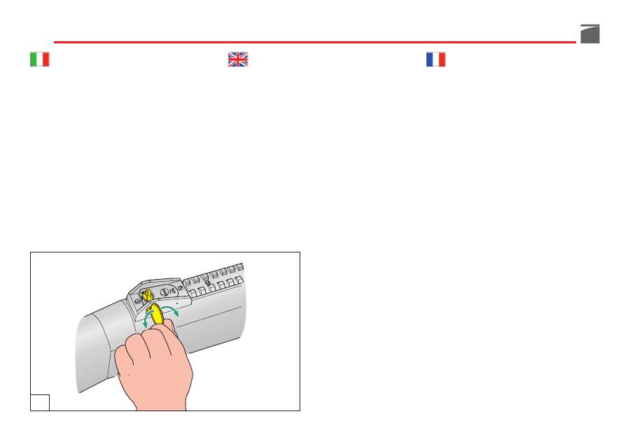
regolare la posizione della tacca di mira nel
senso desiderato (spostare la tacca verso sini-
stra se si intende sparare più a sinistra; verso
destra se si intende sparare più a destra) fa-
cendo riferimento
alle rispettive tacche
gra-
duate di allineamento (fig. 70).
Windage adjustment
Using a coin or the rim of a shell cartridge to
rotate the
windage adjustment screw
(fig.
69), located on the right side of the rear sight
assembly, in the desired direction.
Rotating the windage adjustment screw in a
counter clockwise
direction moves the point-
of-impact on target to the left, in
a clockwise
direction moves the point-of-impact to the
right.
Note on the windage scale
, the amount
of adjustment made (fig. 70).
Réglage latéral hausse
Pour le réglage latéral de la ligne de mire,
prévu sur la
hausse
, procéder comme suit:
Au moyen d’une pièce de monnaie ou du
fond d’une cartouche, régler
la vis prévue
(fig. 69) pour modifier la position de la hausse
dans la direction désirée (déplacer la hausse
vers la gauche pour tirer plus à gauche et vers
la droite pour tirer plus à droite), en se repor-
tant aux
encoches correspondantes
d’aligne-
ment graduées (fig. 70).
69
117
Seitenverstellung
Für die Seitenverstellung der Visierlinie am
Visier
wie folgt vorgehen:
Mit einer Münze oder dem Patronenboden
die
entsprechende Seitenstellschraube
(Abb.
69) drehen und das Visier in der gewünsch-
ten Richtung verstellen (nach links verstellen,
wenn man mehr Linksschuss wünscht, und
nach rechts verstellen, wenn man mehr
Rechtsschuss wünscht). Sich dabei nach den
Einstellstrichen
richten (Abb. 70).
Ajuste lateral
línea de mira
Para el ajuste lateral de la línea de mira, pre-
vista
en el alza
, actúe de la siguiente manera:
Con una moneda o con el fondo de un cartu-
cho
gire el tornillo
(fig. 69) para ajustar la
posición del alza en el sentido deseado
(mover el alza hacia la izquierda si desea
disparar más a la izquierda; hacia la derecha
si desea disparar más a la derecha) tomando
como referencia las
marcas graduadas
de ali-
neación (fig. 70).
Регулирование боковой линии
прицела
Для регулирования боковой линии прицела,
предусмотренной на целике, действовать,
как указано
далее
:
При помощи монеты или дна патрона,
повернуть специальный винт
(рис. 69), и
отрегулировать положение целика в
требуемом направлении (сместить целик
влево, если вы хотите стрелять левее;
сместить целик вправо, если вы хотите
стрелять правее), сверяясь с соответствующими
градуированными
метками
для выравнивания
(рис. 70).
70
118
Regolazione verticale
linea di mira
Per la regolazione verticale della linea di
mira, prevista
sulla tacca di mira
, operare
come segue:
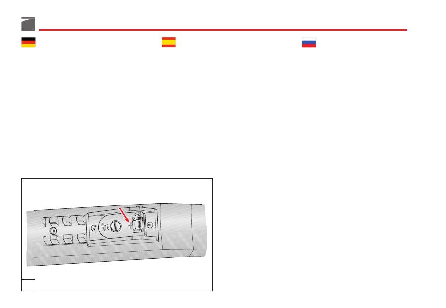
Agendo con una moneta o con il fondello di
una cartuccia,
sulla apposita vite
(fig. 71),
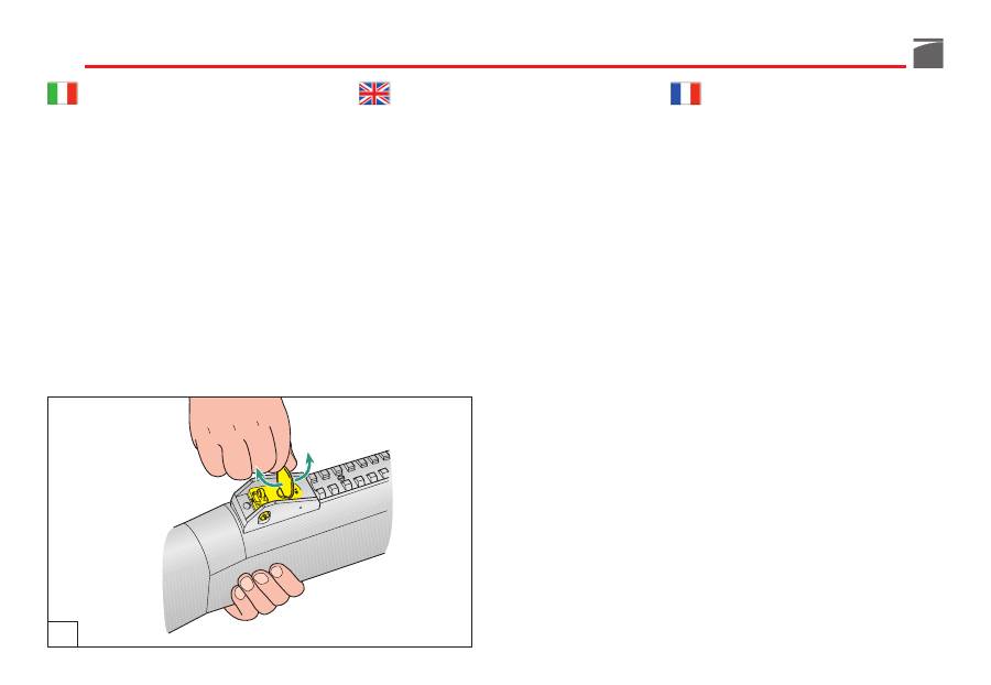
regolare la posizione della tacca di mira nel
senso desiderato (in senso antiorario “up” se
si intende sparare più in alto; al contrario se
si intende sparare più in basso) facendo riferi-
mento alle rispettive intacche graduate di alli-
neamento.
Elevation adjustment
Use a coin or the rim of a shell cartridge to
rotate the
elevation adjustment screw
(fig.
71), located on top of the elevating platform,
in the desired direction.
Rotating the
elevation screw
in a counter
clockwise direction raises the aperture and
the point-of impact of on target, in a clock-
wise direction lowers the aperture and point-
of-impact on target. Note on the elevation
scale on the rear surface of the elevating plat-
form the amount of adjustment made, or
count the tactile clicks of the screw.
Réglage vertical hausse
Pour le réglage vertical de la ligne de mire
prévu sur la
hausse
, procéder comme suit:
Au moyen d’une pièce de monnaie ou du
fond d’une cartouche, régler
la vis prévue
(fig. 71) pour modifier la position de la haus-
se dans la direction désirée (dans le sens
inverse des aiguilles d’une montre pour tirer
plus haut et dans le sens des aiguilles d’une
montre pour tirer plus bas), en se reportant
aux encoches correspondantes d’alignement
graduées.
71
119
Höhenverstellung
Für die Höhenverstellung der Visierlinie am
Visier
wie folgt vorgehen:
Mit einer Münze oder dem Patronenboden
die
entsprechende Höhenstellschraube
(Abb.
71) drehen und das Visier in der gewünsch-
ten Richtung verstellen (gegen den Uhrzeiger-
sinn "up" verstellen, wenn man mehr nach
oben schießen will und umgekehrt, wenn
man mehr nach unten schießen will). Sich
dabei nach den Einstellstrichen richten.
Ajuste vertical
línea de mira
Para el ajuste vertical de la línea de mira, pre-
vista
en el alza
, actúe de la siguiente manera:
Con una moneda o con el fondo de un cartu-
cho
gire el tornillo
(fig. 71) para ajustar la
posición del alza en el sentido deseado (en
sentido contrario al de las manecillas del reloj
“up” si desea disparar más hacia arriba; al
contrario si desea disparar más hacia abajo)
tomando como referencia las
marcas gradua-
das
de alineación.
Регулирование линии прицела
по вертикали
Для регулирования по вертикали линии
прицела, предусмотренной на
целике
,
действовать, как указано далее:
При помощи монеты или дна патрона,
повернуть специальный винт
(рис. 71), и
отрегулировать положение целика в
требуемом направлении (в направлении
против часовой стрелки “вверх”, если вы
хотите стрелять выше; в противоположном
направлении, если вы хотите стрелять
ниже), сверяясь с соответствующими
градуированными
метками
для
выравнивания.

