Eneo PXD-5362F01IR: DE EN FR PL RU
DE EN FR PL RU: Eneo PXD-5362F01IR
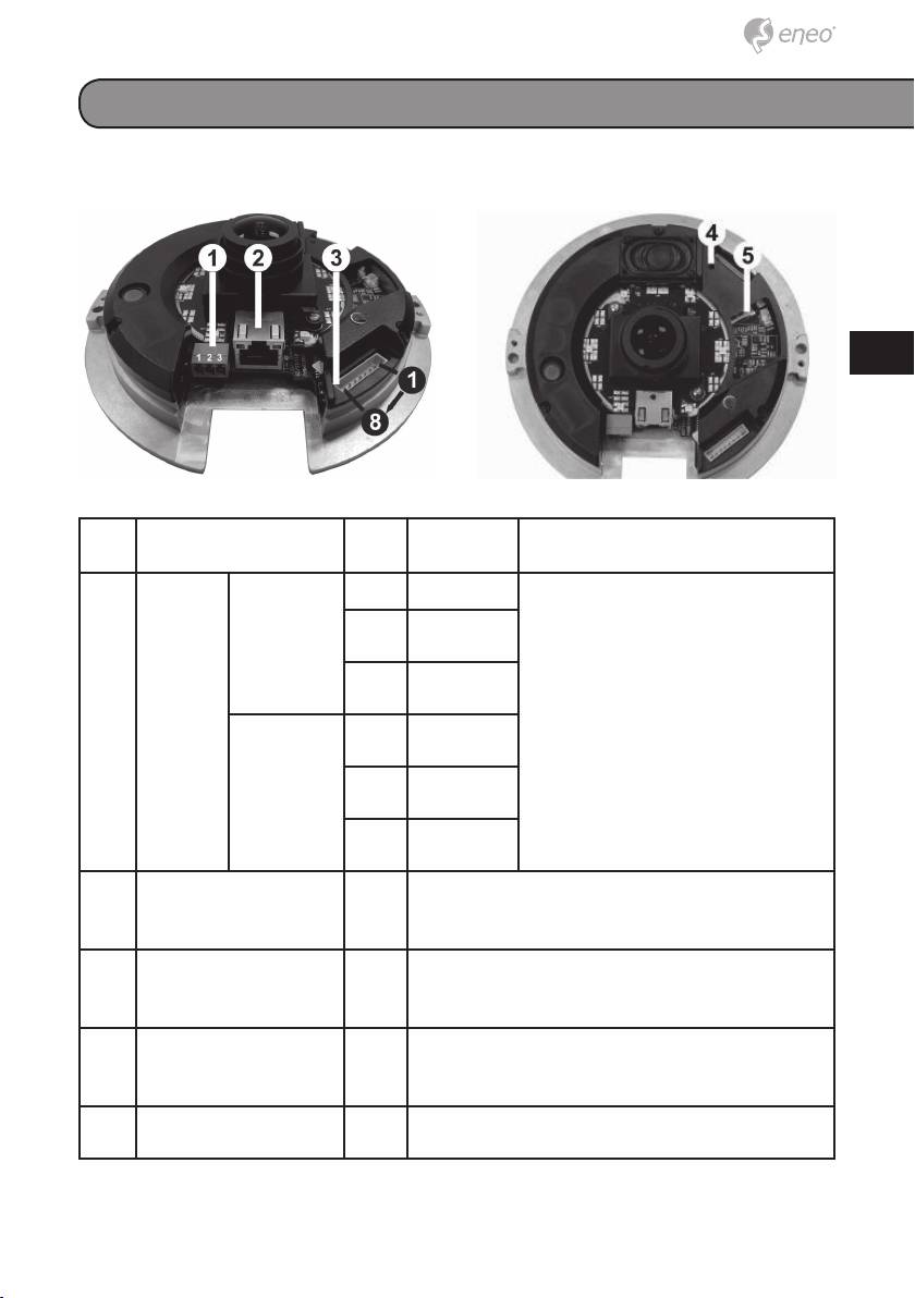
Product description and connections
DE
EN
FR
PL
RU
No. Connector Pin Defi nition Remarks
1 Power* DC 12V 1 Power Power connection
2 Reserved
3 GND
AC 24V 1 Power-1
2 GND
Power-2
2 RJ-45 - 10/100 Mbps Ethernet / PoE (PXD-
5360F01IR)
3 Alarm & Audio I/O* - Please refer to the Alarm & Audio I/O in the
table under Cable Defi nition
4 Reset Button - Restore to default setting; press the button
with a proper tool
5 Micro SD Card Slot - For video recording storage
*All in One Cable is required for Power, Alarm and Audio I/O utilization
13
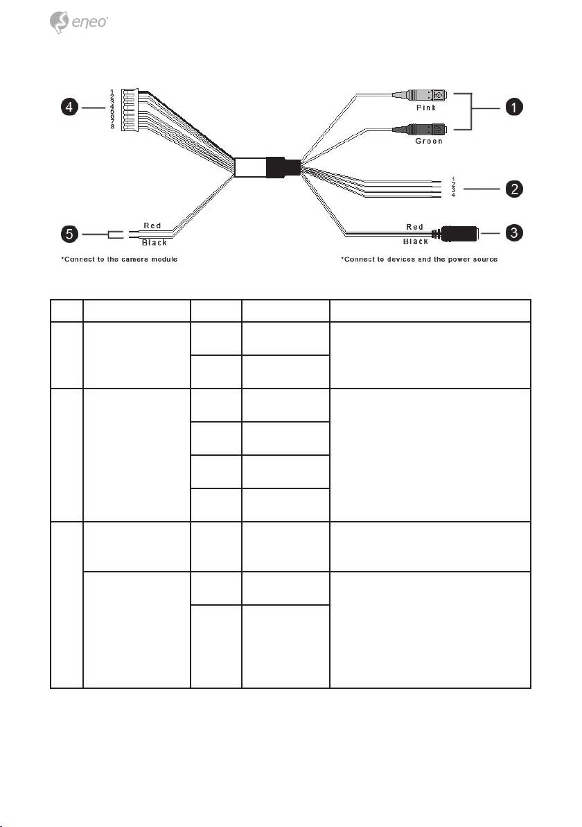
No. Connector Pin Definition Remarks
1 Audio I/O Pink Line In Two-way audio transmission
Green Line Out
2 Alarm (4-Pin
1 ALM_IN – Alarm connection
Terminal Block)
2 ALM_IN +
3 ALM_OUT –
4 ALM_OUT +
3 Power DC Jack - DC 12V Power connection (Tip: +, sleeve:
-)
Power Wires Red AC 24V (+) Remove DC Jack connector
head, and apply AC 24V with
Black AC 24V (–)
Red and Black wires.
Please refer to the section of
Cable Definition in User’s Ma-
nual.
14
