Elta 7537N1: 19. 18.
19. 18.: Elta 7537N1
19. 18.
13.
SERVICING
- The user should not attempt to service the unit beyond that described in the user
operating instructions. All other servicing should be referred to qualified service personnel.
14.
CLEANING
- Disconnect from mains power supply before cleaning. Do not use liquid or spray
cleaners, only use a damp cloth. Follow the care and maintenance instructions in this manual.
15.
LIGHTNING
- During lightning and longer periods of non-use please disconnect from mains
power supply and antenna.
16.
SAFETY CHECK
- After servicing the unit ask the customer service for a safety check.
17.
OVERLOAD
- To avoid fire and electric shock do not overload wall outlets and convenience
receptacles.
18.
ELECTROSTATIC DISCHARGE
- Disconnect from mains power supply and remove batteries if
unit malfunctions. Reconnect after a short time.
CAUTION
THIS CD PLAYER IS A CLASS I LASER PRODUCT. HOWEVER, THIS CD PLAYER USES A
VISIBLE/INVISIBLE LASER BEAM, WHICH COULD CAUSE HAZARDOUS RADIATION
EXPOSURE IF DIRECTED. BE SURE TO OPERATE THE CD PLAYER CORRECTLY AS
INSTRUCTED.
USE OF CONTROLS OR ADJUSTMENTS OR PERFORMANCE OF PROCEDURES OTHER THAN
THOSE SPECIFIED HEREIN MAY RESULT IN HAZARDOUS RADIATION EXPOSURE. DO NOT
OPEN COVERS AND DO NOT REPAIR THE DEVICE YOURSELF. REFER SERVICING TO
QUALIFIED PERSONNEL.
TO REDUCE THE RISK OF FIRE OR ELECTRIC SHOCK AND ANNOYING INTERFERENCE USE
ONLY THE RECOMMENDED ACCESSORIES.
INSTALLATION
Select the mounting location where the unit will not interfere with the normal driving function of the
driver.
Before finally installing the unit, connect the wiring temporarily and make sure it is all connected up
properly and the unit and the system work properly.
Use only the parts included with the unit to ensure proper installation. The use of unauthorized parts
can cause malfunctions.
Consult with your nearest dealer if installation requires the drilling of holes or other modifications of
the vehicle.
Install the unit where it does not get in the driver’s way and cannot injure the passengers if there is a
sudden stop, like an emergency stop.
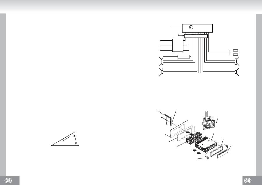
If the installation angle exceeds 30º the
unit might not perform well.
Avoid installing the unit where it is subjected to high temperature, such as from direct sunlight, hot air
from the heating ducts, or where subjected to dust, dirt or excessive vibration.
30˚
DIN front / rear-mount
This unit can be properly installed either from "front" (conventional DIN front-mount) or "rear" (DIN
rear-mount installation, utilizing threaded screw holes at the sides of the unit chassis).
For details, refer to the following illustrated installation methods.
WIRING DIAGRAM
ANTENNA PLUG
ISO CONNECTOR
YELLOW
MEMORY (B+)
BLACK (GND)
RED (B+)
BLUE AUTO ANT
FUSED
FILTER
BOX 1A
& 7A
FUSES
0.5 A
FUSE
WHITE
WHITE / BLACK
GREEN
GREEN / BLACK
GRAY
GRAY / BLACK
VIOLET
VIOLET / BLACK
RCA LINE OUT
RED R
WHITE L
FRONT
LEFT
SP
REAR
FRONT
RIGHT
SP
REAR
METAL STRAP
SELECT THE PROPER
FIXER FOR FIXING THE
SLIDING METAL HOUSING.
UNIT CHASSIS
TO BOOST UP THE CAPABILITY OF ANTI-JAMMING,
PLEASE FIX THE METAL STRAP ON THE METAL
CONNECTED TO THE BOTTOM BRACKET OF THE CAR.
PLASTIC TRIM OUT
FRONT PANEL
DASH BOARD
SLIDING METAL HOUSING
TO DRAW THE CHASSIS OUT OF
THESLIDING METAL HOUSING, INSERTTHE
LEFT AND RIGHT KEY PLATESINTO THE RIGHT
POSITION OF THE 2 SIDES OF CHASSIS.
Оглавление
- 03. 02.
- 05. 04.
- 07. 06.
- 09. 08.
- 11. 10.
- 13. 12.
- 15. 14.
- 17. 16.
- 19. 18.
- 21. 20.
- 23. 22.
- 25. 24.
- 27. 26.
- 29. 28.
- 31. 30.
- 33. 32.
- 35. 34.
- 37. 36.
- 39. 38.
- 41. 40.
- 43. 42.
- 45. 44.
- 47. 46.
- 49. 48.
- 51. 50.
- 53. 52.
- 55. 54.
- 57. 56.
- 59. 58.
- 61. 60.
- 63. 62.
- 65. 64.
- 67. 66.
- 69. 68.
- 71. 70.
- 73. 72.
- 75. 74.
- 77. 76.
- 79. 78.
- 81. 80.
- 83. 82.
- 85. 84.
- 87. 86.
- 89. 88.
- 91. 90.
- 93. 92.
- 95. 94.
- 97. 96.
- 99. 98.
- 101. 100.
- 103. 102.
- 105. 104.
- 107. 106.
- 109. 108.
- 111. 110.
- 113. 112.
- 115. 114.
- 117. 116.
- 119. 118.
- 121. 120.
- 123. 122.
- 125. 124.
- 127. 126.
- 129. 128.
- 131. 130.
- 133. 132.
- 135. 134.
- 137. 136.
- 139. 138.
- 141. 140.
- 143. 142.
- 145. 144.
- 147. 146.
- 149. 148.
- 151. 150.
- 153. 152.
- 155. 154.
- 157. 156.
- 159. 158.
- 161. 160.
- 163. 162.
- 165. 164.
- 167. 166.
- 169. 168.
- 171. 170.
- 173. 172.
- 175. 174.
- 177. 176.
- 179. 178.
- 181. 180.
- 183. 182.
- 185. 184.
- 187. 186.
- 189. 188.
