Stiebel Eltron PSH 30 Trend: inSTALLATion
inSTALLATion: Stiebel Eltron PSH 30 Trend
En
gl
ish
www.stiebel-eltron.com
PSH Trend |
19
inSTALLATion
Safety
inSTALLATion
7. safety
Only a qualified contractor should carry out installation, commis-
sioning, maintenance and repair of the appliance.
7.1 general safety instructions
We guarantee trouble-free function and operational reliability only
if original accessories and spare parts intended for the appliance
are used.
7.2 instructions, standards and regulations
Note
Observe all applicable national and regional regulations
and instructions.
8. appliance description
8.1 standard delivery
The following are delivered with the appliance:
- Safety valve
The safety valve supplied must not be used in Belgium.
For use here please use standard safety valves (see also
pricelist).
8.2 accessories
Pressure-tested taps are available as accessories.
9. Preparations
9.1 installation site
The appliance is designed to be permanently wall-mounted to a
solid surface. Ensure the wall offers adequate load bearing ca-
pacity.
There should be a suitable drain near the appliance to drain off
the expansion water.
Always install the appliance vertically in a room free from the risk
of frost and near the draw-off point.
It may not be fitted in a corner since the screws for fixing the
appliance to the wall must remain accessible.
9.2 Fitting the wall mounting bracket
Note
Ensure that the temperature selector is accessible from
the front.
The mounting bracket attached to the appliance has hook-in slots,
which in most cases enables installation on the bolts that are
already in place from previous appliances.
f
f
Otherwise, transfer the dimensions for the holes to be drilled
on the wall (see chapter "Specification / Dimensions and
connections").
f
f
Drill the holes and secure the wall mounting bracket with
screws and rawl plugs. Select fixing materials in accordance
with the wall construction/condition.
f
f
Hook the appliance with wall mounting brackets on to the
screws or bolts. Observe the weight of the appliance when
empty (see chapter "Specification / Data table") and, if neces-
sary, ask another person to help.
f
f
Align the appliance horizontally.
20
| PSH Trend www.stiebel-eltron.com
inSTALLATion
installation
10. installation
10.1 water connection
!
Material losses
Carry out all water connection and installation work in
accordance with regulations.
Operate the appliance only with pressure-tested taps.
10.1.1 Permissible materials
!
Material losses
When using plastic pipework, observe the manufacturer's
data and the chapter "Specification / Fault conditions".
cold water line
Galvanised steel, stainless steel, copper and plastic are approved
materials.
dHw line
Stainless steel, copper and plastic pipework are approved ma-
terials.
10.1.2 Fitting the safety valve
Note
The safety valve supplied must not be used in Belgium.
For use here please use standard safety valves (see also
pricelist).
Note
If the water pressure is greater than 0.6 MPa, install a
pressure reducing valve in the "cold water inlet".
The maximum permissible pressure must not be exceeded (see
chapter "Specification / Data table").
f
f
Install a type-tested safety valve in the cold water supply
line. Please note that, depending on the static pressure, you
may also need a pressure reducing valve.
f
f
Size the drain so that water can drain off unimpeded when
the safety valve is fully opened.
f
f
Fit the discharge pipe of the safety valve with a constant
downward slope and in a room free from the risk of frost.
f
f
The safety valve discharge aperture must remain open to the
atmosphere.
10.2 Power supply
WARNING Electrocution
Carry out all electrical connection and installation work
in accordance with relevant regulations.
Before any work on the appliance, disconnect all poles
from the power supply.
WARNING Electrocution
Only use a permanent connection to the power supply.
The appliance must be able to be separated from the
power supply by an isolator that disconnects all poles
with at least 3 mm contact separation.
WARNING Electrocution
Ensure that the appliance is earthed.
!
Material losses
Observe the type plate. The specified voltage must match
the mains voltage.
Power cable
DANGER Electrocution
The power cable must only be replaced (for example
if damaged) with the original spare part by a qualified
contractor authorised by the manufacturer.
The appliance is supplied with a flexible power cable with wire
ferrules and without plug, ready to connect.
f
f
If the power cable is of insufficient length, unclamp it from
the appliance. Use a suitable installation cable.
f
f
When routing the new power cable, ensure that it is water-
proof as it passes through the existing cable grommet, and is
correctly routed and connected inside the appliance.
En
gl
ish
www.stiebel-eltron.com
PSH Trend |
21
inSTALLATion
commissioning
11. commissioning
11.1 commissioning
Note
Fill the appliance with water prior to electrical connec-
tion. If you switch on the appliance while empty, the high
limit safety cut-out will switch it off.
f
f
Thoroughly flush out the cold water line before connecting
the appliance, so that no foreign matter gets into the water
heater or safety valve.
f
f
Open the shut-off valve in the cold water feed line.
f
f
Open a draw-off point until the appliance has filled up and
the pipework is free of air.
f
f
Adjust the flow rate. For this, observe the maximum permis-
sible flow rate with a fully opened tap (see chapter "Specifi-
cation / Data table").
f
f
If necessary reduce the flow rate at the butterfly valve of the
safety valve.
f
f
Turn the temperature selector to maximum.
f
f
Switch the mains power ON.
f
f
Check the function of the appliance. Ensure that the thermo-
stat switches off.
f
f
Check that the safety valve is working correctly.
11.1.1 appliance handover
f
f
Explain the function of the appliance and safety valve to
users and familiarise them with their operation.
f
f
Make users aware of potential dangers, especially the risk of
scalding.
f
f
Hand over these instructions.
11.2 recommissioning
See chapter "Commissioning".
12. shutting down
f
f
Disconnect the appliance from the mains at the MCB/fuse in
the fuse box.
f
f
Drain the appliance. See chapter "Maintenance / Draining the
appliance".
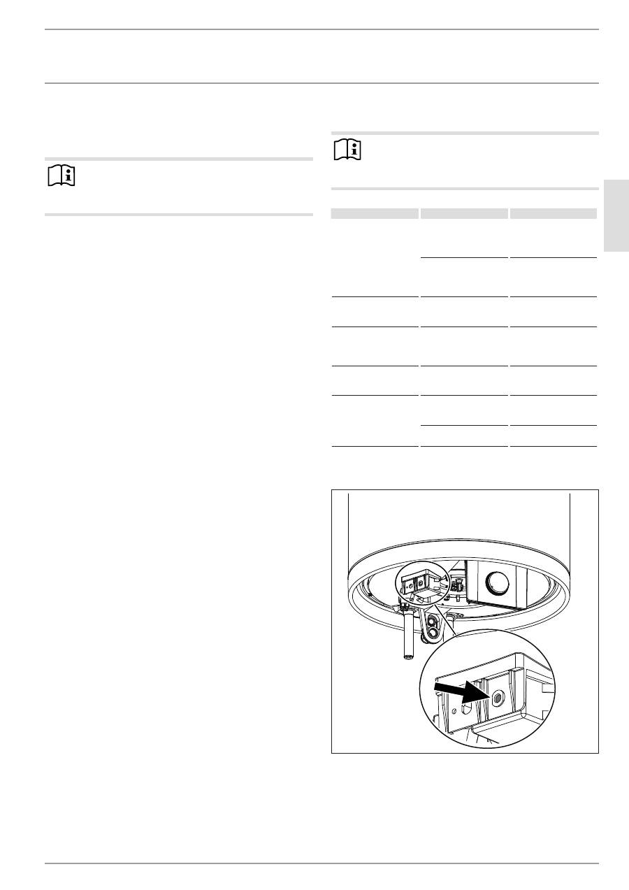
13. troubleshooting
Note
The high limit safety cut-out can respond at temperatures
below –15 °C. The appliance may be subjected to these
temperatures during storage or transport.
fault
cause
remedy
The water does not heat
up and the ON/OFF indi-
cator does not illuminate.
The high limit safety
cut-out has responded
because the controller is
faulty.
Remedy the cause of the
fault. Replace the con-
troller.
The high limit safety
cut-out has responded
because the temperature
has fallen below -15 °C.
Press the reset button
(see diagram).
The water does not heat
up and the ON/OFF indi-
cator illuminates.
The heating element is
faulty.
Replace the heating el-
ement.
The water does not heat
up sufficiently and the
ON/OFF indicator illumi-
nates.
The temperature control-
ler is faulty.
Replace the temperature
controller.
The heat-up time is very
long and the ON/OFF in-
dicator illuminates.
The heating element is
scaled up.
Descale the heating el-
ement.
The safety valve drips
when heating is switched
off.
The valve seat is contam-
inated.
Clean the valve seat.
Water pressure is too
high.
Install a pressure reduc-
ing valve.
reset key, high limit safety cut-out
D
00000
37
14
3
22
| PSH Trend www.stiebel-eltron.com
inSTALLATion
Maintenance
14. maintenance
WARNING Electrocution
Carry out all electrical connection and installation work
in accordance with relevant regulations.
Before any work on the appliance, disconnect all poles
of the appliance from the power supply.
If you need to drain the appliance, observe chapter "Draining the
appliance".
14.1 checking the safety valve
f
f
Test the safety valve regularly.
14.2 draining the appliance
WARNING Burns
Hot water may escape during the draining process.
If is necessary to drain the cylinder for maintenance or to protect
the whole installation from frost, proceed as follows:
f
f
Close the shut-off valve in the cold water feed line.
f
f
Open the DHW valves of all draw-off points until the appli-
ance is fully drained.
f
f
Drain any residual water from the safety valve.
14.3 checking / replacing the protective anode
f
f
Check the protective anode after the first year of use and re-
place if necessary.
f
f
Next, decide the time intervals at which further checks
should be carried out.
14.4 descaling
f
f
Remove loose scale deposits from the water heater.
f
f
If necessary, descale the inner cylinder with commercially
available descaling agents.
f
f
Only descale the flange after disassembly and never treat the
cylinder surface and protective anode with descaling agents.
14.5 anti-corrosion protection
Ensure that while carrying out maintenance work the anti-corro-
sion protection (560 Ω) is not damaged or removed. Reinsert the
anti-corrosion protection correctly after replacement.
D
00000
37
14
1
14.6 replacing the power cable
DANGER Electrocution
The power cable must only be replaced (for example
if damaged) with the original spare part by a qualified
contractor authorised by the manufacturer.
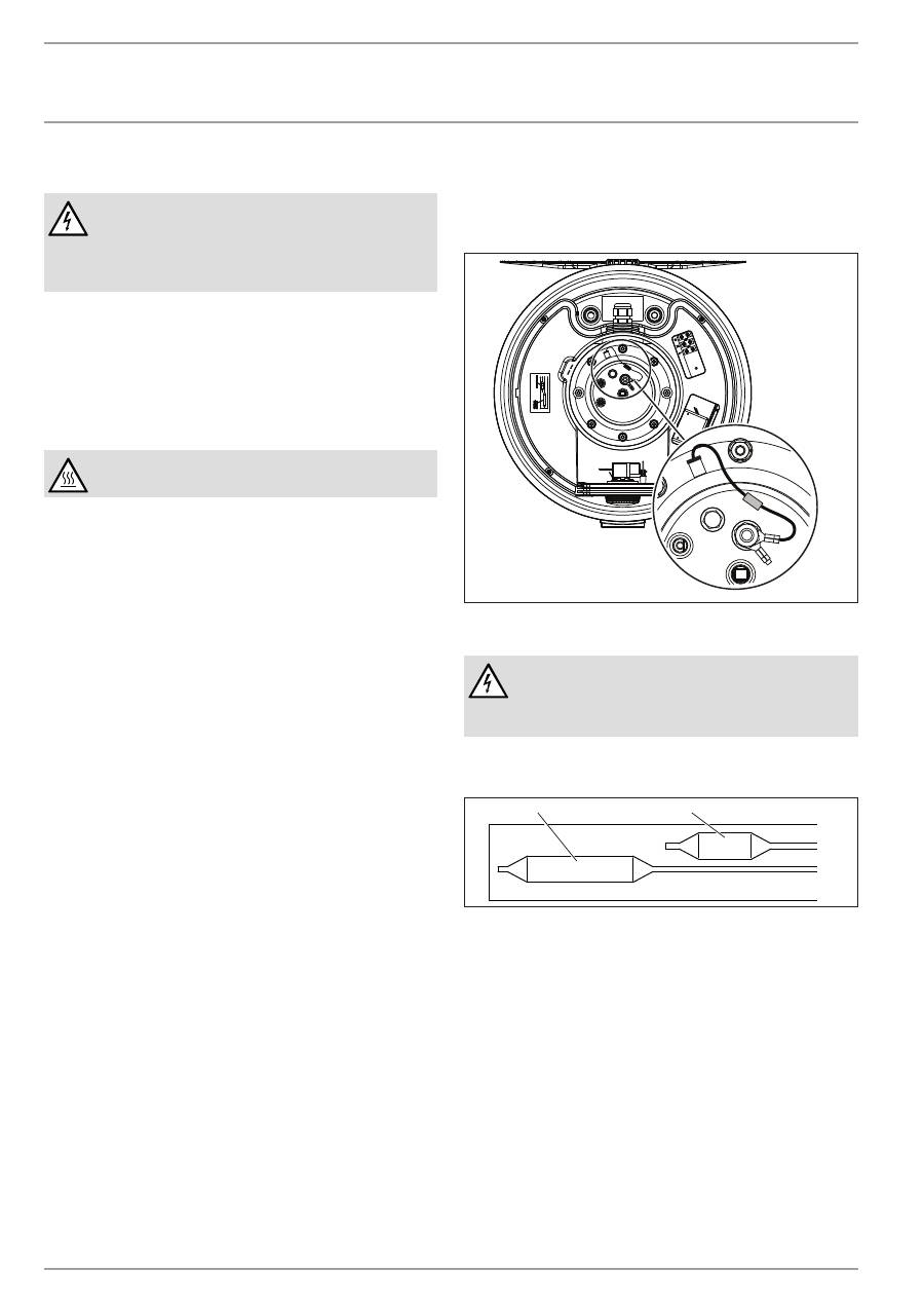
14.7 replacing the combined controller/limiter
D
00000
37
14
2
2
1
1 Controller sensor
2 Limiter sensor
f
f
Insert the controller sensor and the limiter sensor into the
sensor well as far as they will go.
En
gl
ish
www.stiebel-eltron.com
PSH Trend |
23
inSTALLATion
Specification
15. specification
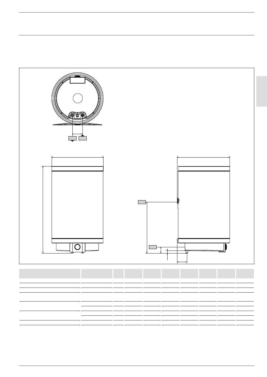
15.1 dimensions and connections
c01
c06
i13
b01
a10
100
a40
a30
61
23
D
00000
37
13
5
PSH 30
Trend
PSH 50
Trend
PSH 80
Trend
PSH 100
Trend
PSH 120
Trend
PSH 150
Trend
PSH 200
Trend
a10 Appliance
Height
mm
635
890
860
1015
1170
1400
1705
a30 Appliance
Depth
mm
410
410
520
520
520
520
520
a40 Appliance
Diameter
mm
405
405
510
510
510
510
510
b01 Entry electrical cables
Threaded fitting
M20x1.5
(PG 16)
M20x1.5
(PG 16)
M20x1.5
(PG 16)
M20x1.5
(PG 16)
M20x1.5
(PG 16)
M20x1.5
(PG 16)
M20x1.5
(PG 16)
c01 Cold water inlet
Male thread
G 1/2 A
G 1/2 A
G 1/2 A
G 1/2 A
G 1/2 A
G 1/2 A
G 1/2 A
Rear clearance
mm
85.5
85.5
95
95
95
95
95
c06 DHW outlet
Male thread
G 1/2 A
G 1/2 A
G 1/2 A
G 1/2 A
G 1/2 A
G 1/2 A
G 1/2 A
Rear clearance
mm
85.5
85.5
95
95
95
95
95
i13 Wall mounting bracket
Height
mm
530
590
520
790
825
1060
1360
24
| PSH Trend www.stiebel-eltron.com
inSTALLATion
Specification
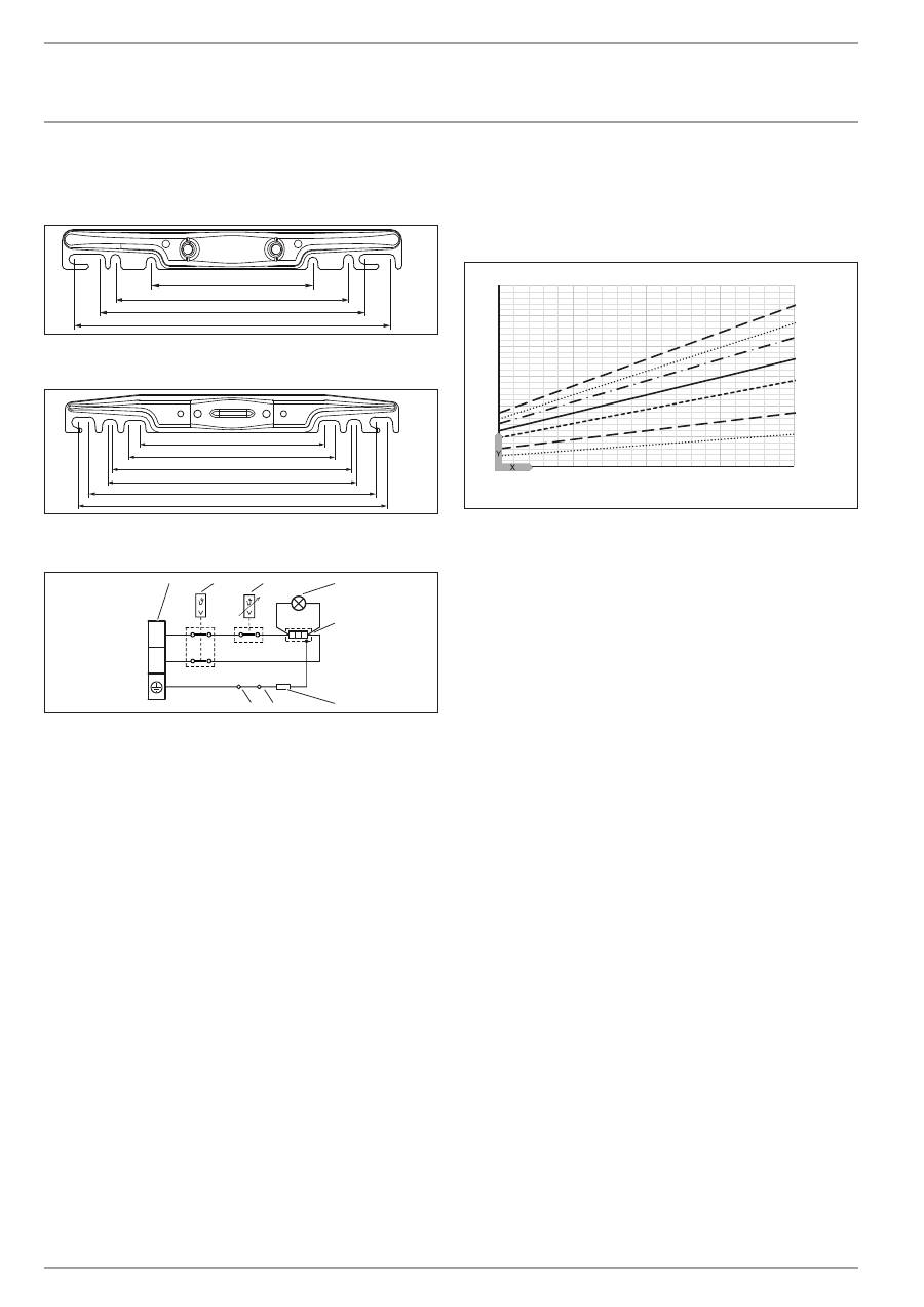
wall mounting bracket
30 - 50 l
184
265
300
360
80
�0
2�
07
�0
00
5
80 - 200 l
450
415
360
350
300
265
80
�0
2�
07
�0
00
6
15.2 wiring diagram
N
L
2
1
3
4
5
6
7
8
85
�0
2�
07
�0
01
0
1 Terminal
2 High limit safety cut-out
3 Temperature controller
4 ON/OFF indicator
5 Heating element
6 Electrical resistance 560 ohm
7 Anode
8 Cylinder
15.3 Heat-up diagrams
The heat-up time depends on the cylinder capacity, cold water
inlet temperature and heating output.
Graph assumes 15 °C cold water inlet temperature:
0
1
2
3
4
5
6
35
45
55
65
75
1
2
7
6
5
4
3
D
00000
37
21
4
X Temperature setting [°C]
Y Heat-up time [h]
1 150 l
2 200 l
3 120 l
4 100 l
5 80 l
6 50 l
7 30 l
15.4 Fault conditions
In the event of a fault, temperatures of up to 95 °C at 0.6 MPa
can occur.
En
gl
ish
www.stiebel-eltron.com
PSH Trend |
25
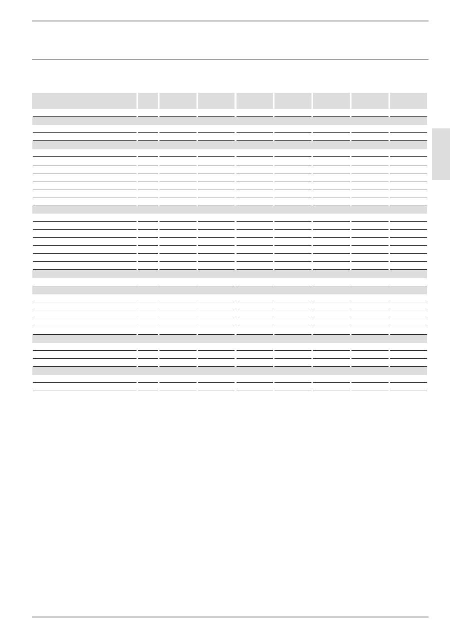
15.5 data table
PSH 30
Trend
PSH 50
Trend
PSH 80
Trend
PSH 100
Trend
PSH 120
Trend
PSH 150
Trend
PSH 200
Trend
232080
232081
232082
232083
232084
232085
232086
Hydraulic data
Nominal capacity
l
30
50
80
100
120
150
200
Amount of mixed water 40 °C (15 °C/65 °C)
l
52
99
142
186
224
288
376
Electrical data
Connected load ~ 230 V
kW
2
2
2
2
2
2
3
Rated voltage
V
220-240
220-240
220-240
220-240
220-240
220-240
220-240
Phases
1/N/PE
1/N/PE
1/N/PE
1/N/PE
1/N/PE
1/N/PE
1/N/PE
Frequency
Hz
50/60
50/60
50/60
50/60
50/60
50/60
50/60
Single circuit operating mode
X
X
X
X
X
X
X
Heat-up time 2.0 kW (15 °C/60 °C)
h
0.80
1.33
2.13
2.66
3.20
4.00
Heat-up time 3.0 kW (15 °C/60 °C)
h
3.55
Application limits
Temperature setting range
°C
7-75
7-75
7-75
7-75
7-75
7-75
7-75
Max. permissible pressure
MPa
0.6
0.6
0.6
0.6
0.6
0.6
0.6
Test pressure
MPa
0.2
0.2
0.2
0.2
0.2
0.2
0.2
Max. permissible temperature
°C
95
95
95
95
95
95
95
Max. flow rate
l/min
23.5
23.5
23.5
23.5
23.5
23.5
23.5
Min. water inlet pressure
MPa
0.1
0.1
0.1
0.1
0.1
0.1
0.1
Max. water inlet pressure
MPa
0.6
0.6
0.6
0.6
0.6
0.6
0.6
Energy data
Standby energy consumption/24 h at 65 °C
kWh
0.53
0.72
0.79
0.98
1.14
1.33
1.61
Versions
Colour
White
White
White
White
White
White
White
IP rating
IP25
IP25
IP25
IP25
IP25
IP25
IP25
Sealed unvented type
X
X
X
X
X
X
X
Power cable
X
X
X
X
X
X
X
Power cable length approx.
mm
1000
1000
1000
1000
1000
1000
1000
Dimensions
Height
mm
635
890
860
1015
1170
1400
1705
Depth
mm
410
410
520
520
520
520
520
Diameter
mm
405
405
510
510
510
510
510
Weights
Weight, empty
kg
16.4
21.4
28.2
33.6
39.1
46.2
56.3
Weight, full
kg
46.4
71.4
108.2
133.6
159.1
196.2
256.3
wArrAnTy environMenT And recycLing
Warranty
The warranty conditions of our German companies do not
apply to appliances acquired outside of Germany. In countries
where our subsidiaries sell our products, it is increasingly the
case that warranties can only be issued by those subsidiaries.
Such warranties are only granted if the subsidiary has issued
its own terms of warranty. No other warranty will be granted.
We shall not provide any warranty for appliances acquired in
countries where we have no subsidiary to sell our products.
This will not affect warranties issued by any importers.
Environment and recycling
We would ask you to help protect the environment. After use,
dispose of the various materials in accordance with national
regulations.
inSTALLATion | wArrAnTy | environMenT And recycLing
Specification


