Pfannenberg PYRA PY X-M Series: инструкция
Раздел: Безопасность
Тип:
Инструкция к Pfannenberg PYRA PY X-M Series
PY X-M/ PY X-MA- Blitzleuchte - Betriebs- und Montageanleitung
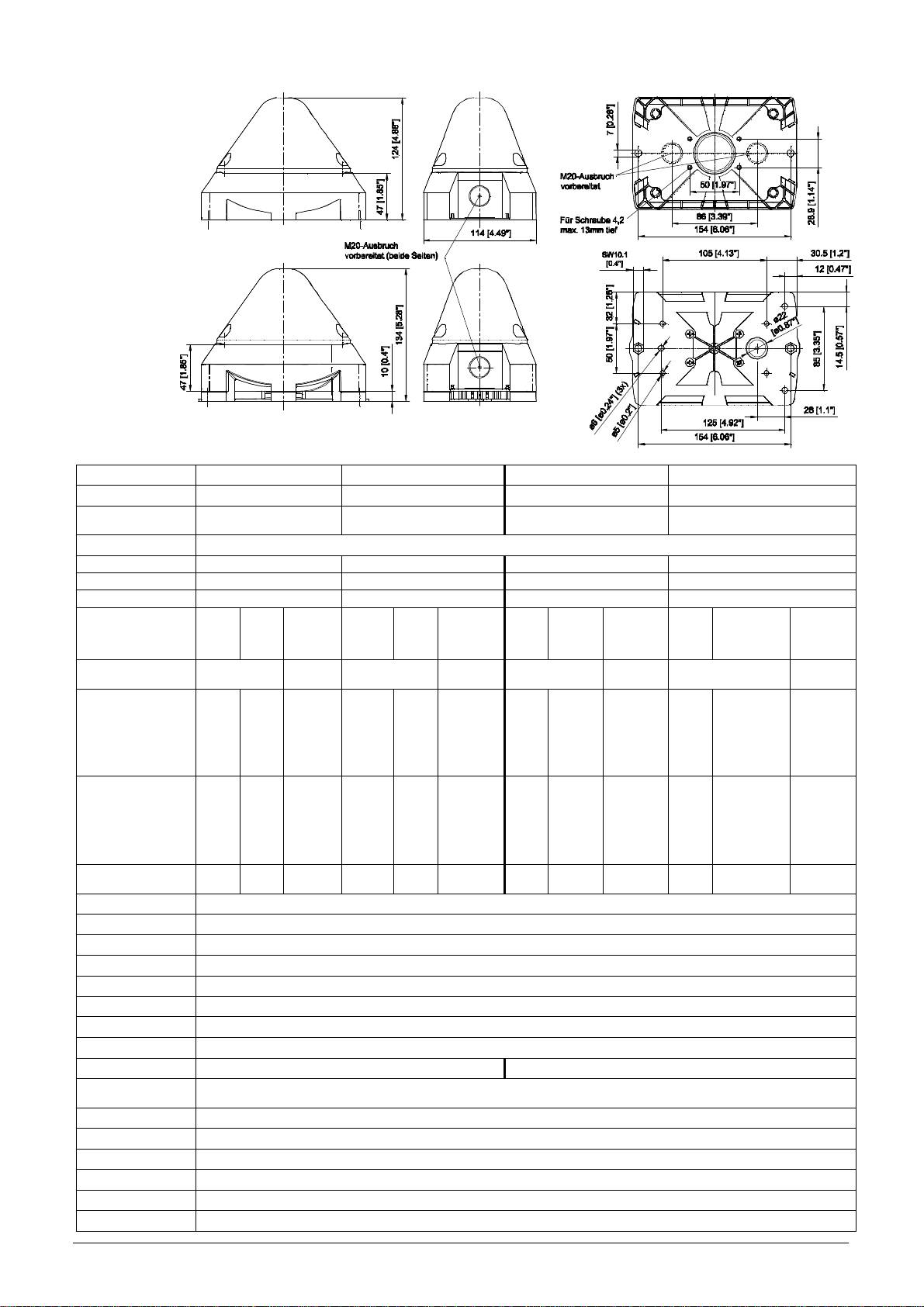
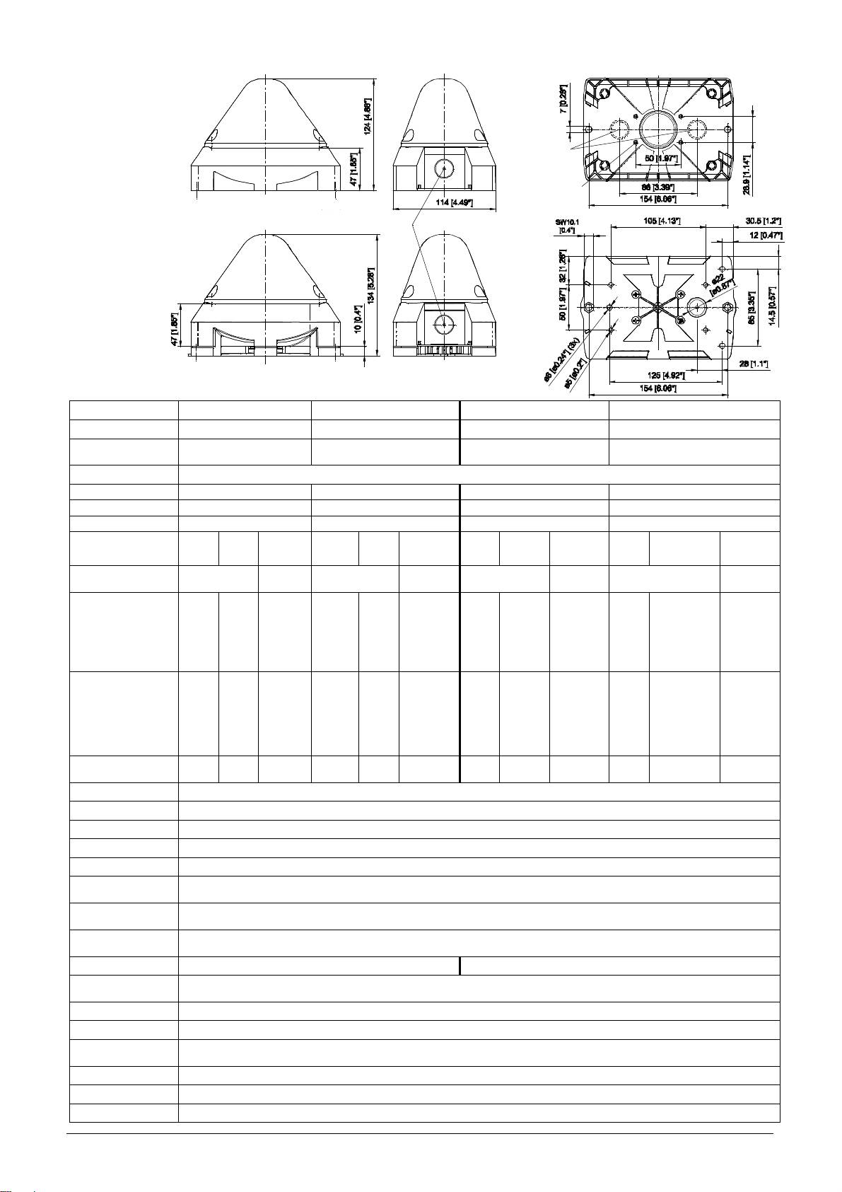
Maße
PY X-M-xx
PY X-MA-xx
Technische Daten
PY X-M-05 PY X-M-10 PY X-MA-05 PY X-MA-10
Blitzenergie 5J 10J 5J 10J
Effektive
44 cd (klar) 118 cd (klar) 44 cd (klar) 118 cd (klar)
Nennlichtstärke
Blitzfolgefrequenz 0,1 / 0,5 / 0,75 / 1 Hz
Nennschallpegel - - 100dB (A) 1m 100dB (A) 1m
Lautstärkeregelung - - max. - 20 dB max. - 20 dB
Töne - - 8 8
Bemessungs-
230V
spannung
085 501 972 30360-004 1
115V
AC
24V
AC
AC/DC
230V
115V
AC
AC
24V AC/DC
230V
115V
AC
AC
24V AC/DC
230V
115V
AC
AC
24V AC/DC
50/60 Hz/
Nennfrequenz 50/60 Hz
50/60 Hz/
50/60 Hz/
50/60 Hz/
50/60 Hz
50/60 Hz
50/60 Hz
DC
DC
DC
DC
Funktionsbereich
187-255V
90 – 135V
AC:18 – 30V
DC: 10 – 60V
187– 255V
90 – 135V
AC:18 – 30V
DC: 10 – 60V
187– 255V
90 – 135V
AC:18 – 30V
DC: 10 – 60V
187– 255V
90 – 135V
AC:18 – 30V
DC: 10 – 60V
Strom-
aufnahme (1Hz)
60
110
150
240
[mA]
70 - 75
120 - 140
160 - 165
250 - 270
AC: 600
DC: 280@24V
AC: 1000
DC: 540
@24V
AC: 660–720
DC: 290-360
@24V
AC: 1050-
1150
DC: 550–620
@24V
Leistungsaufnahme 13,8VA
12,7VA
AC:14,4VA
34,5VA
DC:6,7W
27,6VA
AC:24VA
17,3VA
DC: 13W
AC:17,3VA
16,1VA
AC:27,6VA
38VA 31VA
DC: 8,6W
DC:14,9W
Einschaltdauer 100%
Anschlussklemmen 0,14 - 2,5mm² feindrähtig / AWG24 - AWG 14 (stranded)
Schutzart IP66 (EN60529), Type 4 & 4x
Schlagfestigkeit IK 08 (EN50102)
Schutzklasse II
Betriebstemperatur -40°C…+55°C
Lagertemperatur -40°C…+70°C
Max. rel. Luftfeuchte
Kartoninhalt:
1x Alarmgerät
1x Membrannippel M20
1x Betriebsanleitung
90%
Kabeleinführung 4x M20 vorgeprägt 3x M20 vorgeprägt
Dichtbereich der
7 – 13 mm - Bei Verwendung von Kabeldurchmessern < 7 mm ist eine Kabelverschraubung mit ausreichender
Durchführungstülle
Schutzart vorzusehen
Gehäusematerial PC/ABS Blend
Haubenmaterial PC
Einbaulage beliebig
Option Aktivierungseingang
Zubehör Plombierstopfen (Art.-Nr. 28300000002)
Haubenfarben klar, weiß, gelb, orange, rot, grün, blau
Zulassungen
Zulassungen
(gilt für gekennzeichnete Betriebsmittel)
Bauproduktrichtlinie
PY X-M-05 + PY X-M-10: VdS 0786-CPD-xxxx (in Vorbereitung)
(89/106/EWG)
Bemessungsspannung 12V DC 24V DC 48V DC
Spannungsbereich gemäß EN54-23 10V – 60V DC
Haubenfarbe rot, klar
EN 54-23 Kategorie O:
Signalisierungsbereich
siehe Dokument 30360-005-1
Umweltschutzklasse Typ B
Einbaulage siehe Dokument 30360-005-1
Die Prüfung erfolgte unter Verwendung des mitgelieferten Membrannippels und der äußeren
Befestigungsbohrungen.
PY X-M-05 + PY X-M-10: G212xxx, Daten siehe Bauproduktenrichtlinie (89/106/EWG)
UL, cUL
PY X-M-xx + PY X-MA-xx: UEES, UEES7 (weiterführende Informationen siehe Seite 5)
in Vorbereitung
Inbetriebnahme
Sicherheitshinweise:
- Der elektrische Anschluss darf nur von hierfür autorisierten Personen in Übereinstimmung mit den derzeit gültigen
Vorschriften durchgeführt werden.
- Warnung vor gefährlicher hoher elektrischer Spannung.
- Vor dem Öffnen ist sicherzustellen, dass das Gerät nicht unter Spannung steht.
- Vor Inbetriebnahme ist die auf dem Typenschild angegebene Versorgungsspannung zu kontrollieren. Eine falsche
Betriebsspannung kann zur Schädigung bzw. zur Zerstörung des Betriebsmittels führen.
- Bei der Installation ist darauf zu achten, dass die Anschlussleitung gegen Zug und Verdrehen abgesichert ist.
Bitte beachten: Die Geräte sind nicht für einen ortsveränderlichen Einsatz bestimmt.
- WARNUNG: Bei Installation Verdrahtung entfernt von scharfen Kanten, Ecken und internen Komponenten vornehmen.
- Die Funktion des Gerätes ist nur gewährleistet, wenn Ober- und Unterteil korrekt zusammengefügt sind.
- Um eine Beeinträchtigung des Sehvermögens zu verhindern, ist der dauernde, direkte Blick in die aktivierte Leuchte zu
vermeiden.
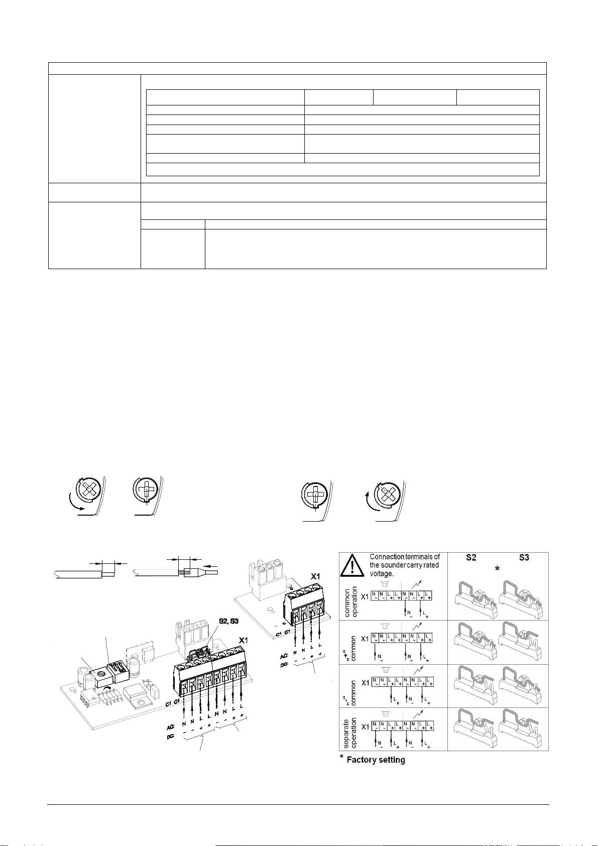
Öffnen des Gehäuses: Verschließen des Gehäuses
1. 2.
1. 2.
Verschließen des Gehäuses
Durch Lösen der vier
durch Drehen der
Deckelschrauben lässt
Deckelschrauben in die
sich das Oberteil
Endstellung bis zur
3/8
abnehmen
3/8
Verrastung.
Das Gerät wird in nicht verschlossenem Zustand ausgeliefert.
Plombierstopfen für die Gehäuseschrauben sind als Zubehör erhältlich.
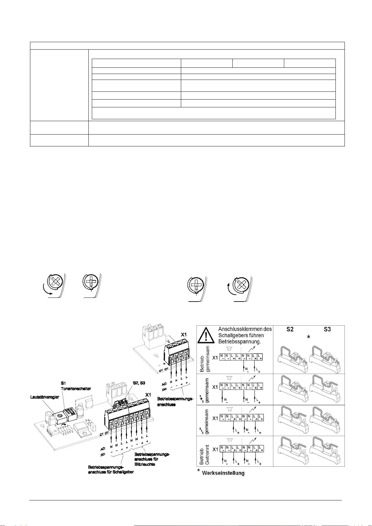
Elektrischer Anschluss:
PY X-M-
Die Leuchten erfüllen die Anforderungen der EN54-23 (Gleichlauf).
Achtung: Um einen Gleichlauf sicherzustellen, müssen die Geräte zwingend mit demselben Potential betrieben werden
.
085 501 972 30360-004 2
xx
PY X-MA-xx
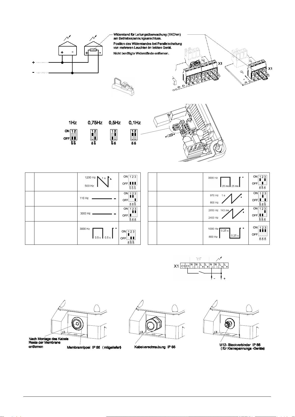
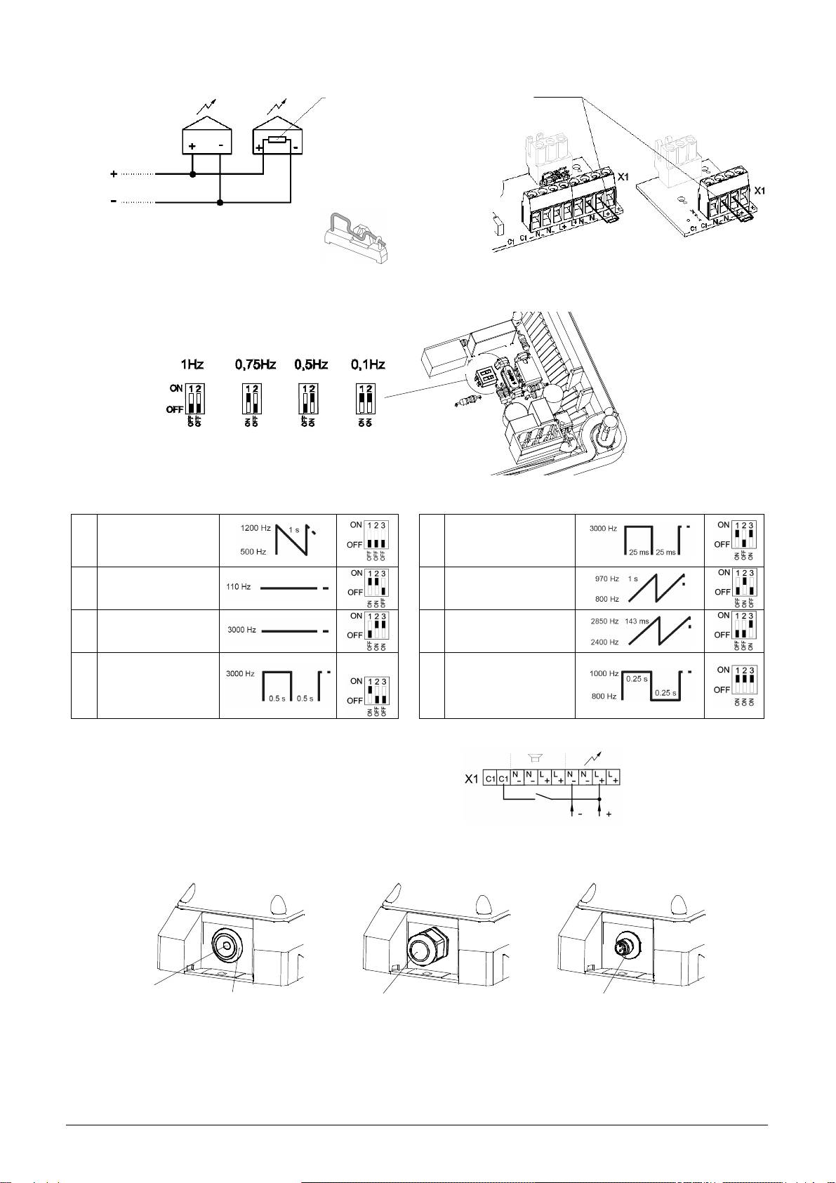
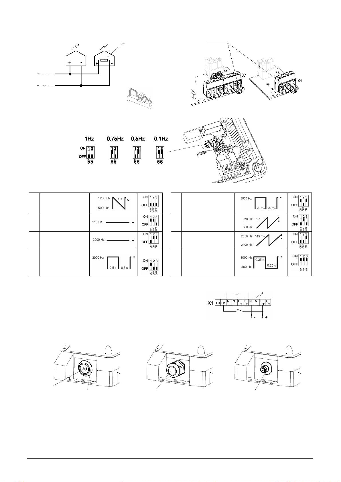
Anschluss eines Widerstandes zur Leitungsüberwachung:
Einstellung der Blitzfrequenz
:
*
* Werkseinstellung
Einstellung der Tonarten:
Sägezahn
DIN 33404-3
1
5
Unterbrochener Ton
(Notsignal)
PFEER PTAP
085 501 972 30360-004 3
2
Dauerton (Horn)
Ansteigender Ton
6
Feueralarm
UK BS5839-1
3
Dauerton
7
Ansteigender Ton
4
Unterbrochener Ton
*
Wechselton
UK BS5839-1,
8
Feueralarm
Bahnübergang
PY X-MA-xx PY X-M-xx
Platine
in der Haube
*
Werkseinstellung, Tonartenschalter S1 auf Platine im Unterteil, siehe Kapitel „elektrischer Anschluss“.
Leuchten mit Aktivierungseingang (für PY X-M-xx)
Bei dieser Option kann die Blitzleuchte mittels Steuerspannung aktiviert
werden. Die Leistungsaufnahme des Steuereingangs beträgt max. 1W.
Kabeldurchführungen
Zur Sicherstellung der angegebenen Schutzart sind an den dafür vorgesehenen Durchbrüchen Kabeldurchführungen mit
einer Schutzart von IP 66 zu montieren. Der mitgelieferte Membrannippel kann durch eine Kabelverschraubung oder durch
einen M12-Steckverbinder mit einem Flanschmaß von M20 ersetzt werden.
Wartung, Service, Instandhaltung
Das Gerät erfordert keine besondere Wartung. Die äußere Reinigung sollte mit einer schwachen Seifenlösung ohne
Verwendung von Lösungsmittel erfolgen.
Die Blitzleuchte darf nur in unbeschädigtem Zustand innerhalb der spezifizierten Kenndaten betrieben werden. Umbauten,
Änderungen, fehlerhafter und unzulässiger Einsatz sowie die Nichtbeachtung der Hinweise dieser Betriebsanleitung
schließen eine Gewährleistung aus.
Ein Austausch von Komponenten darf nur mit Originalersatzteilen erfolgen. Reparaturen sind grundsätzlich im Herstellerwerk
auszuführen.
Bei Leitungsüberwachung mit Spannungsumkehr
muss die Verpolungsschutzdiode mit dem Öffnen des
Schalters S4 (auf der Platine in der Haube) aktiviert
we
rden.
S4
*
Werks-
einstellung
Operating and installation instruction for PY X-M/ PY X-MA beacon
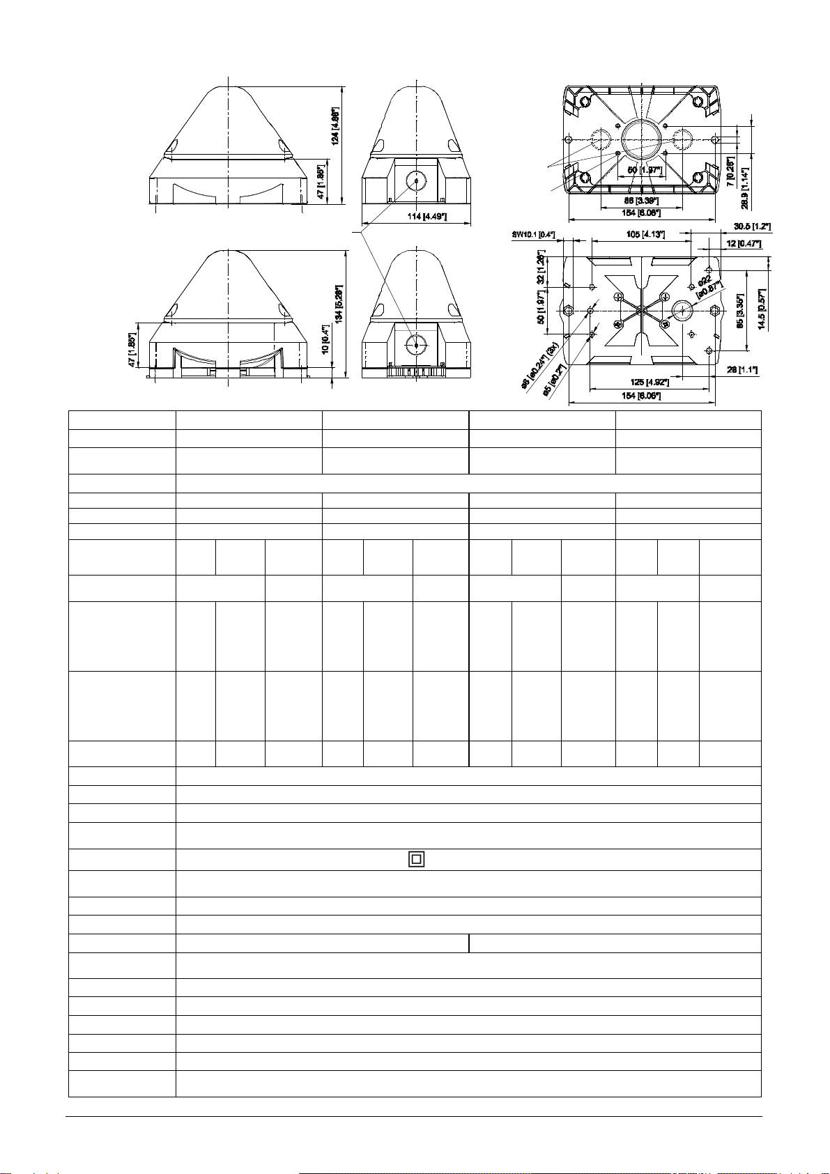
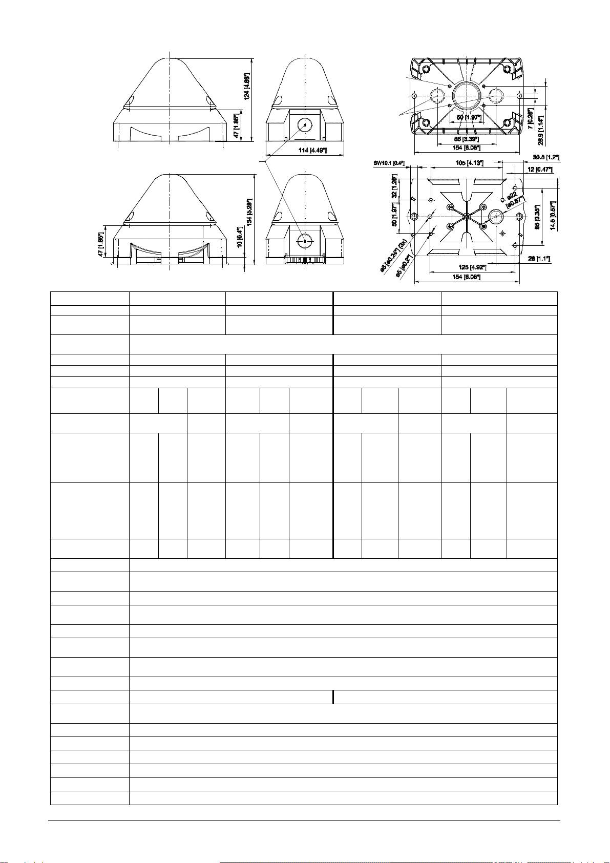
Dimensions
PY X-M-xx
PY X-MA-xx
Technical Data
PY X-M-05 PY X-M-10 PY X-MA-05 PY X-MA-10
Flash energy 5J 10J 5J 10J
Rated effective
44 cd (clear) 118 cd (clear) 44 cd (clear) 118 cd (clear)
luminous intensity
Flash frequency 0,1 / 0,5 / 0,75 / 1 Hz
Nom. sound level - - 100dB (A) 1m 100dB (A) 1m
Volume control - - max. - 20 dB max. - 20 dB
Tones - - 8 8
230V
Rated voltage
085 501 972 30360-004 4
115V
AC
24V
230V
115V
24V
230V
115V
24V
230V
115V
AC
AC/DC
AC
AC
AC/DC
AC
AC
AC/DC
AC
AC
24V AC/DC
50/60 Hz/
50/60 Hz/
50/60 Hz/
Frequency 50/60 Hz
50/60 Hz
50/60 Hz
DC
DC
50/60 Hz/
50/60 Hz
DC
DC
Operating voltage
range
187-255V
90 – 135V
AC:
18 – 30V
DC:
10 – 60V
187– 255V
90 – 135V
AC:18 – 30V
DC: 10 – 60V
187– 255V
90 – 135V
AC:18 – 30V
DC: 10 – 60V
187– 255V
90 – 135V
AC:18 – 30V
DC: 10 – 60V
Power
Consumption (1Hz)
60
110
150
240
[mA]
70 - 75
120 - 140
160 - 165
250 - 270
AC: 600
DC:
280 @24V
AC: 1000
DC:
540 @24V
AC: 660–720
DC: 290-360
@24V
AC:
1050-1150
DC: 550–620
@24V
Power consumption 13,8VA
AC:14,4VA
12,7VA
34,5VA
DC:6,7W
AC:24VA
27,6VA
DC: 13W
17,3VA
AC:17,3VA
16,1VA
DC: 8,6W
AC:27,6VA
38VA 31VA
DC:14,9W
Duty cycle 100%
Connection terminal
0,14 - 2,5mm² / AWG24 - AWG 14 (stranded)
Protection system IP66 (EN60529) , Type 4 & 4x
Resistance against
IK 08 (EN50102)
impact
Protection class
II Double insulated equipment
Operating
-40°C…+55°C
temperature
Storage temperature
-40°C…+70°C
Max. rel. Humidity 90%
Cable entry 4x M20 (prepared) 3x M20 (prepared)
Sealing range of
7 – 13 mm - With the use of cable diameters <7 mm, a cable screw joint
grommet
Content of package:
Prepared M20 piercing
1x Alarm device
(both sides)
1x Diaphragm nipple M20
1x Operating instruction
with sufficient ingress protection must be provided
Material of housing PC/ABS Blend
Material of lens PC
Installation position arbitrary
Option Control input
Accessory Sealing plug (part-no. 28300000002)
clear, white, yellow, amber, red, green, blue
Lens colours
Prepared M20
Piercing
For screw 4,2
Depth: max 13mm
Approvals
Approvals
(valid for marked equipment)
Construction Product
PY X-M-05 + PY X-M-10: VdS 0786-CPD-xxxx
Directive
Rated voltage
(89/106/EWG)
12V DC 24V DC 48V DC
Operating voltage range acc. to EN54-23 10V – 60V DC
(in preparation)
Lens colours red, clear
Signalling area EN 54-23 Category O: see document 30360-005-1
Environmental
Type B
protection class
Installation position see document 30360-005-1
Testing takes place using the supplied diaphragm nipple and the outer fastening bores.
VdS
PY X-M-05 + PY X-M-10:
G212xxx, data see Construction Product Directive (89/106/EWG)
in preparation
PY X-M-xx + PY X-MA-xx
Rated Voltage Visual Signal Appliance - General Signaling Equipment - UEES, UEES7
UL, cUL
115V AC
Suitable for indoor and outdoor use.
in preparation
230V AC
Warning: Not to be used as a Visual Public Mode Alarm Notification Appliance.
According to CSA-C22.2 No. 205-M1983 clause 4.3.4 the connection is limited to max. three
24V AC/ DC
leads.
PYRA Xenon beacons PY X-M(A)-xx comply with the limits for a Class A digital device, pursuant to part 15 of the FCC Rules.
Taking into Operation
Safety notes:
- Installation must be carried out by an electrician in compliance with the latest codes and regulations.
- Danger: High voltage may be present.
- Prior to opening, it must be ensured that no voltage is applied to the device.
- Before electrical connection, the supply voltage on the type plate is to be checked. The wrong operating voltage can lead to
damages or to the destruction of the equipment.
- During installation it must be ensured that the connection cables are secured against tension and distortion.
Please observe: The devices are not designed for portable use.
- CAUTION: When making installation, route field wiring away from sharp projections, corners and internal components.
- The function of the unit is only guaranteed if the upper and lower section is joined correctly.
- In order to prevent detriment to sight, continuously looking directly in the activated light is to be avoided.
Opening the housing Closing the housing
1. 2.
1. 2.
3/8
3/8
The unit is not closed when delivered. Sealing plugs for the housing screws are available as accessories.
Electrical connection:
PY X-M-
Connecting cables
The beacons satisfy the requirements of the standard EN54-23 (Synchronization).
Caution: In order to ensure synchronization, the devices must be operated with the same potential..
085 501 972 30360-004 5
xx
By loosing the four
7 [0.28"]
7 [0.28"]
stranded
solid
Connection for
operation voltage
cover screws, the upper
The housing is closed by
turning the cover screws to
the limit position until the
section can be
housing locks into place.
removed.
S1,
Tone Selector Switch
Volume
Control
Operation voltage for
Operation voltage
PY X-MA-xx
for beacon
sounder
Line monitoring:
Flash Frequency adjustment:
*
* Factory setting
Tone table (for PY X-MA-xx):
Sawtooth
DIN 33404-3
1
5
Interrupted tone
(Emergency signal)
PFEER PTAP
085 501 972 30360-004 6
Continuous tone
2
(Horn)
Slow whoop
6
Fire alarm
UK BS5839-1
3
Continuous tone
7
Slow whoop
4
Interrupted tone
*
Alternating tone,
UK BS5839-1,
8
Fire alarm, railway
crossing
Resistor for Line Monitoring (1K Ohm)
at the terminal for operating voltage.
Position of the resistor with parallel
connection of multiple beacons in the
last unit
PY X-MA-xx PY X-M-xx
PCB
in lens
*
Factory setting, Tone selector switch S1 on pcb inside base part, see chapter „electrical connection“.
Devices with control input (for PY X-M-xx)
This option allows the beacon to be activated via control voltage.
The maximum current consumption of the control input is max. 1W.
Cable gland entries
To guarantee the specified protection type, cable grommets with a protection type of IP 66 are to be installed at the openings
provided for this purpose. The supplied diaphragm nipple can be replaced with a cable gland or with an M12 plug connection
with a flange measurement of M20.
Maintenance, Service and Ordering Spare Parts
The device does not require any special maintenance. External cleaning should be done with a mild soap solution without the
use of solvents. The device may only be operated in the undamaged state within the specified rating.
Conversions, alterations, improper and inadmissible use as well as the non-observance of the notes in these operating
instructions shall render the warranty null and void. Components may be replaced only by original spare parts. As a matter of
principle, repairs are to be carried out in the manufacturing works.
Remove unneeded resistors
.
After installation of the cable
remove the remains of the
Diaphragm nipple IP 66
Cable gland IP 66
M12 plug connector IP 66
(provided)
(for low voltage versions)
diaphragm.
When the line monitoring is used with reverse
voltage the blocking diode must be activated by
opening the Switch S4 (on pcb inside lens).
S4
*
Factory
setting
Utilisation et de montage pour lampe flash PY X-M/ PY X-MA
Dimensions
PY X-M-xx
PY X-MA-xx
Caractéristiques techniques
PY X-M-05 PY X-M-10 PY X-MA-05 PY X-MA-10
Energie lumineuse
085 501 972 30360-004 7
5J 10J 5J 10J
Nom. intensité
44 cd (clair) 118 cd (clair) 44 cd (clair) 118 cd (clair)
lumineuse effective
Fréquence du
0,1 / 0,5 / 0,75 / 1 Hz
clignotement
Niveau sonore nom.
- - 100dB (A) 1m 100dB (A) 1m
Réglage du volume
- - max. - 20 dB max. - 20 dB
Sons - - 8 8
230V
Tension de service
115V
CA
24V
CA
CA/CC
230V
115V
CA
24V
230V
CA
CA/CC
115V
24V
230V
115V
24V
CA
CA
CA /CC
CA
CA
CA /CC
Fréquence nom. 50/60 Hz
50/60 Hz/
50/60 Hz/
50/60 Hz/
50/60 Hz/
50/60 Hz
50/60 Hz
50/60 Hz
CC
CC
CC
CC
Plage de la tension
de service
187-255V
90 – 135V
AC:18 – 30V
DC: 10 – 60V
187– 255V
90 – 135V
AC:18 – 30V
DC: 10 – 60V
187– 255V
90 – 135V
AC:18 – 30V
DC: 10 – 60V
187– 255V
90 – 135V
AC:18 – 30V
DC: 10 – 60V
Courant nominal
(1Hz)
60
110
[mA]
CA: 600
CC: 280 @24V
150
240
CA: 1000
CC: 540 @24V
70 - 75
120 - 140
160 - 165
250 - 270
CA: 660–720
CC: 290-360
@24V
CA: 1050-1150
CC: 550–620
@24V
Puissance 13,8VA
12,7VA
CA:14,4VA
34,5VA
CC:6,7W
27,6VA
CA:24VA
17,3VA
CC: 13W
CA:17,3VA
16,1VA
CA:27,6VA
38VA 31VA
CC: 8,6W
CC:14,9W
Facteur de marche 100%
Bornes de
0,14 - 2,5 mm² en fils de faible diamètre/ AWG24 - AWG 14 (stranded)
connexion
Type de protection IP66 (EN60529) , Type 4 & 4x
Résistance aux
IK 08 (EN50102)
chocs
Classe de protection
II
Température de
-40°C…+55°C
service
Température de
-40°C…+70°C
stockage
Humidité rel. max. 90%
Entrée de câbles 4 x M20 avec empreinte préalable 3 x M20 avec empreinte préalable
Zone d’intensité du
7 – 13 mm, En cas d’utilisation de câbles de diamètre < 7 mm, un raccord de câble équipé d’un type de
profilé de protection
protection suffisant sera à prévoir
Matériau du boîtier Mélange PC/ABS
Matériau du capot
PC
Position de montage
Contenu de l’emballage :
1 alarme
1 raccord fileté
à membrane M20
1 instruction d’utilisation
quelconque
Option Entrée de commande
Accessoires Bouchon de plombier (art. n° 28300000002)
Couleurs du capot Clair, blanc, jaune, orange, rouge, vert, bleu
Encoche préparée pour le M20
(2x)
Encoche
préparée pour
Pour vis 4,2
le M20
profondeur:
13mm maxi
Admissions
Admissions
(valable pour les appareils signalés)
Directive sur les
PY X-M-05 + PY X-M-10: VdS 0786-CPD-xxxx (en préparation)
produits de
construction
Tension de service 12V CC 24V CC 48V CC
(89/106/CEE)
Plage de tension de service selon EN 54-23 12V – 60V CC
Couleur du capot rouge, clair
EN 54-23 Catégorie O:
Plage de signalisation
voir document 30xxx-005-1
Classe de protection environnementale Type B
Position de montage voir document 30xxx-005-1
Le test a été effectué en utilisant le raccord fileté de membrane livré et les perçages extérieurs de fixation.
VdS
PY X-M-05 + PY X-M-10:
en préparation
G212xxx, pour les caractéristiques voir la Directive sur les Produits de construction (89/106/CEE)
UL, cUL
PY X-M-xx + PY X-MA-xx
: UEES, UEES7 (plus d'informations voir page 5)
en préparation
Mise en service
Consignes de sécurité :
- Le branchement électrique doit être effectué uniquement par des personnes autorisées conformément aux réglementations en
vigueur.
- Attention à la tension électrique élevée. Danger !
- Avant d'ouvrir, il convient de s'assurer que l’appareil est hors tension.
- La tension d'alimentation indiquée sur la plaque signalétique doit être vérifiée avant la mise en service. Une tension de service
incorrecte peut entraîner un endommagement ou la destruction de l’appareil.
- Il convient de veiller, lors de l'installation, que les cordons d’alimentation ne sont pas soumis à des contraintes de traction ou
de torsion. Attention : les appareils ne sont pas destinés à une utilisation mobile.
- AVERTISSEMENT : lors de l’installation, maintenir les câblages éloignés des bords coupants, coins et composants internes.
- Le fonctionnement de l’appareil n’est garanti que si les parties supérieure et inférieure sont assemblées correctement.
- Pour éviter un risque d'endommagement de l'acuité visuelle, il convient d'éviter le contact visuel direct et permanent avec la
lampe.
Ouverture du boîtier
Fermeture du boîtier
1. 2.
1. 2.
Le boîtier se referme en
La partie supérieure
tournant les vis du couvercle
peut être retirée en
desserrant les quatre
3/8
vis du couvercle
3/8
L’appareil est livré en état non verrouillé.
Des bouchons de plombier sont disponibles en accessoires pour les vis du boîtier.
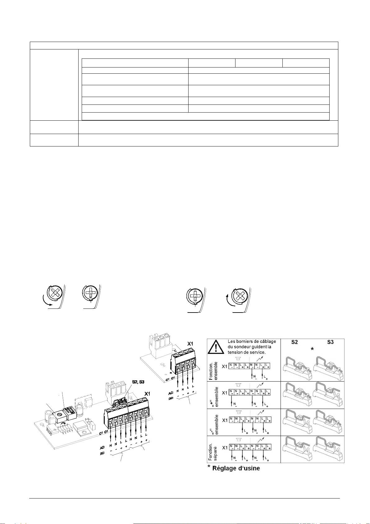
Raccordement à la tension de service:
Les appareils répondent aux exigences de la norme EN54-23 (synchronisme).
Attention: pour assurer le synchronisme, les appareils doivent impérativement être utilisés avec le même potentiel.
085 501 972 30360-004 8
jusqu’en position finale pour
le verrouillage.
PY X-M-
PY X-MA-xx
xx
S1,
Interrupteur de
tonalité
Régulateur du
volume
Raccordement à la
tension de service
Raccordement à la
tension de service
Raccordement à la
pour le feu flash
tension de service pour
la sirène
Résistance pour la surveillance de ligne
Réglage de la fréquence du flash
:
*
*
Réglage d‘usine
Réglage des types de sons (pour PY X-MA-xx) :
Sirène lente
DIN 33404-3 (Signale
1
5
Son intermittent
d’alarme)
PFEER PTAP
085 501 972 30360-004 9
2
Son continu (Horn)
Sirène montante
6
Son évacuation urgence
UK BS5839-1
3
Son continu
7
Sirène montante
4
Son intermittent
*
Modulé bi-ton
UK BS5839-1,
8
Alarme incendie
passage à niveau
PY X-MA-xx PY X-M-xx
Platine
dans le capot
*
Réglage d'usine, commutateur des types de sons S1 sur la platine dans la partie inférieure, voir le chapitre « Branchement
électrique ».
Lampes flashes avec entrée d'activation (pour PY X-M-xx)
Avec cette option, la lampe du flash peut être activée à l'aide de la tension de
commande. L'entrée de commande consomme au maxi. 1 W.
Passages de câbles
Afin de garantir le type de protection indiqué, des passages de câbles d’une protection IP 66 doivent être montés au niveau
des perçages prévus à cet effet. Le raccord fileté à membrane fourni peut être remplacé par un passe-câble à vis ou par un
connecteur M12 avec une bride de dimension M20.
Raccord fileté à membrane
Maintenance, SAV, entretien
L’appareil ne requiert aucune maintenance particulière. Le nettoyage extérieur doit être effectué avec une solution
légèrement savonneuse, sans solvants.
L’appareil doit être exploité uniquement en bon état de marche et dans le respect des caractéristiques indiquées. Toute
transformation, modification, utilisation incorrecte ou inadmissible ainsi que le non-respect des instructions de service
entraînent l'exclusion de la garantie.
Tous les composants doivent être remplacés uniquement par des pièces originales. Les réparations doivent en principe être
effectuées dans les ateliers du fabricant.
Passe-câble à vis IP 66
Connecteur M12 IP 66
IP 66 (fourni)
(pour appareils très basse tension)
Résistance pour surveillance de ligne
(1KOhm) au niveau du raccordement à la
tension de service.
Position de la résistance en branchement
en parallèle de plusieurs feux flash sur le
dernier appareil.
Ôter les résistances qui ne sont pas
nécessaires.
Pour la surveillance de ligne avec renversement de
tension, la diode de protection de la polarité doit
Après le montage du câble,
ôter le reste de la membrane
être activée à l'ouverture du commutateur S4 (sur la
platine dans le capot).
S4
*
Réglage
d‘usine
Проблесковая лампа PY X-M/ PY X-MA Инструкция по монтажу и эксплуатации
Размеры
PY X-M-xx
PY X-MA-xx
Технические данные
PY X-M-05 PY X-M-10 PY X-MA-05 PY X-MA-10
Blitzenergie 5
Дж
10
Дж
5
Дж
10
Дж
Effektive
44 cd (
прозрачная
) 118 cd (
прозрачная
) 44 cd (
прозрачная
) 118 cd (
прозрачная
)
Nennlichtstärke
Частота
вспышки
0,1 / 0,5 / 0,75 / 1
Гц
Ном
.
уровень
звука
085 501 972 30360-004 10
- - 100
дБ
(A) 1
м
100
дБ
(A) 1
м
Регулировка
звука
- -
макс
. -20
дБ
макс
. -20
дБ
Тон
- - 8 8
Рабочее
230B
напряжение
115B
AC
24B
AC
AC/DC
230B
115B
AC
24B
AC
AC/DC
230B
115B
24B
AC
AC
AC/DC
230B
115B
24B
AC
AC
AC/DC
Номинальная
50/60
Гц
/
50/60
Гц
частота
50/60
Гц
/
50/60
Гц
/
50/60
Гц
/
50/60
Гц
50/60
Гц
50/60
Гц
DC
DC
DC
DC
B
B
B
B
B
B
B
B
Диапазон
рабочего
напряжения
187-255 B
90 – 135 B
AC:18 – 30
DC: 10 – 60
187– 255 B
90 – 135 B
AC:18 – 30
DC: 10 – 60
187– 255 B
90 – 135 B
AC:18 – 30
DC: 10 – 60
187– 255 B
90 – 135 B
AC:18 – 30
DC: 10 – 60
B
B
Номинальный
ток
(1
Гц
)
60
110
150
240
[
мА
]
AC: 600
DC: 280@24
AC: 1000
DC: 540 @24
70 - 75
120 - 140
160 - 165
250 - 270
AC: 660–720
DC: 290-360
@24 B
AC: 1050-
1150
DC: 550–620
@24 B
Мощность
13,8VA
12,7VA
AC:14,4VA
DC:6,7ВТ
34,5VA
27,6VA
AC:24VA
DC: 13
ВТ
17,3VA
AC:17,3VA
16,1VA
DC: 8,6ВТ
AC:27,6VA
38VA 31VA
DC:14,9
ВТ
Рабочий
цикл
100%
Соединения
0,14 - 2,5
мм
²,
с
тонким
проводом
/ AWG24 - AWG 14 (
многожильное
)
Тип
защиты
IP66 (EN60529) , Type 4 & 4x
Ударная
прочность
IK 08 (EN50102)
Класс
защиты
II
Рабочая
-40°C…+55°C
температура
Температура
-40°C…+70°C
хранения
Макс
.
отн
.
влажность
воздуха
90%
Кабельный
ввод
M20, 4
шт
,
предварительно
подготовлены
M20, 3
шт
,
предварительно
подготовлены
Допустимый
7 – 13
мм
;
при
использовании
кабеля
диаметром
менее
7
мм
должна
применяться
резьбовая
диаметр
кабеля
Содержимое упаковки:
1 устройство сигнализации
1 мембранный ниппель М20
1 руководство по эксплуатации
втулка
с
соответствующим
классом
защиты
Материал
корпуса
Поликарбонат
/
акрилонитрил
-
бутадиен
-
стирол
Материал
линзы
PC
Монтажное
Произвольное
положение
Опции
Вход
управления
Аксессуары
Пломбировочные
пробки
(
арт
. 28300000002)
Цвет
линзы
прозрачная
,
белый
,
жёлтый
,
оранжевый
,
красный
,
зелёный
,
синий
Отверстие М20 (подготовлено)(2x)
Отверстие М20
(подготовлено)
Для винта
4,2,
Глубина макс.
13мм
Допуски
Допуски
(
только
для
оборудования
с
маркировкой
)
Директива
PY X-M-05 + PY X-M-10: VdS 0786-CPD-xxxx (в процессе подготовки)
Европейского
Союза
по
строительным
Рабочее
напряжение
12V
пост
.
тока
24V
пост
.
тока
48V
пост
.
тока
изделиям
Диапазон
рабочего
напряжения
10 – 60
В
(89/106/EWG)
согласно
EN54-23
Цвет
линзы
красный
,
прозрачный
Область
применения
оповещения
EN 54-23
категория
O:
см
.
документ
30360-005-1
Класс
защиты
окружающей
среды
Б
Монтажное
положение
см
.
документ
30360-005-1
Испытания
проводились
с
использованием
мембранного
ниппеля
(
в
комплекте
)
и
вне
085 501 972 30360-004 11
шних
крепежных
отверстий
.
Союз
страховщиков
в процессе
PY X-M-05 + PY X-M-10:
G212xxx,
см
.
Директиву
ЕС
по
строительным
изделиям
(89/106/EWG)
подготовки
UL, cUL
в процессе
PY X-M-xx + PY X-MA-xx:
UEES, UEES7 (
Дополнительную
информацию
см
.
на
стр
.)
подготовки
Ввод в эксплуатацию
Указания по технике безопасности:
- Подключение электрооборудования разрешается выполнять только уполномоченным сотрудникам в соответствии с
предписаниями действующего законодательства.
- Осторожно: высокое напряжение.
- Во время монтажных работ питание должно быть отключено от устройства.
- Перед вводом в эксплуатацию следует проверить соответствие напряжения данным, указанным на заводской
табличке. При подключении неверного напряжения оборудование может быть повреждено или выведено из строя.
- Во время монтажа необходимо предусмотреть меры, чтобы проводка не могла быть вытянута или перекручена.
Следует принять во внимание, что данные устройства не являются переносными.
- ВНИМАНИЕ! При монтаже кабель не должен касаться острых краёв, углов и внутренних компонентов.
- Корректная работа устройства гарантируется только в том случае, если верхняя и нижняя части смонтированы
правильно.
- Чтобы исключить отрицательное влияние на зрение, не рекомендуется долго смотреть на включенную
проблесковую лампу.
Открывание корпуса: Закрывание корпуса
1. 2.
1. 2.
3/8
3/8
Устройство поставляется в открытом состоянии.
В качестве аксессуаров предлагаются пломбировочные пробки.
Электрическое подключение:
PY X-M-
Огни отвечают требованиям стандарта EN54-23 (синхронность).
Внимание: Для
обеспечения
синхронности
функционирования
,
устройства
должны
эксплуатироваться
с
одинаковым
потенциалом
.
xx
Верхнюю часть можно
Корпус закрывается путём
снять после поворота
поворота винтов крышки
винтов крышки.
до фиксации в конечном
положении.
PY X-MA-xx
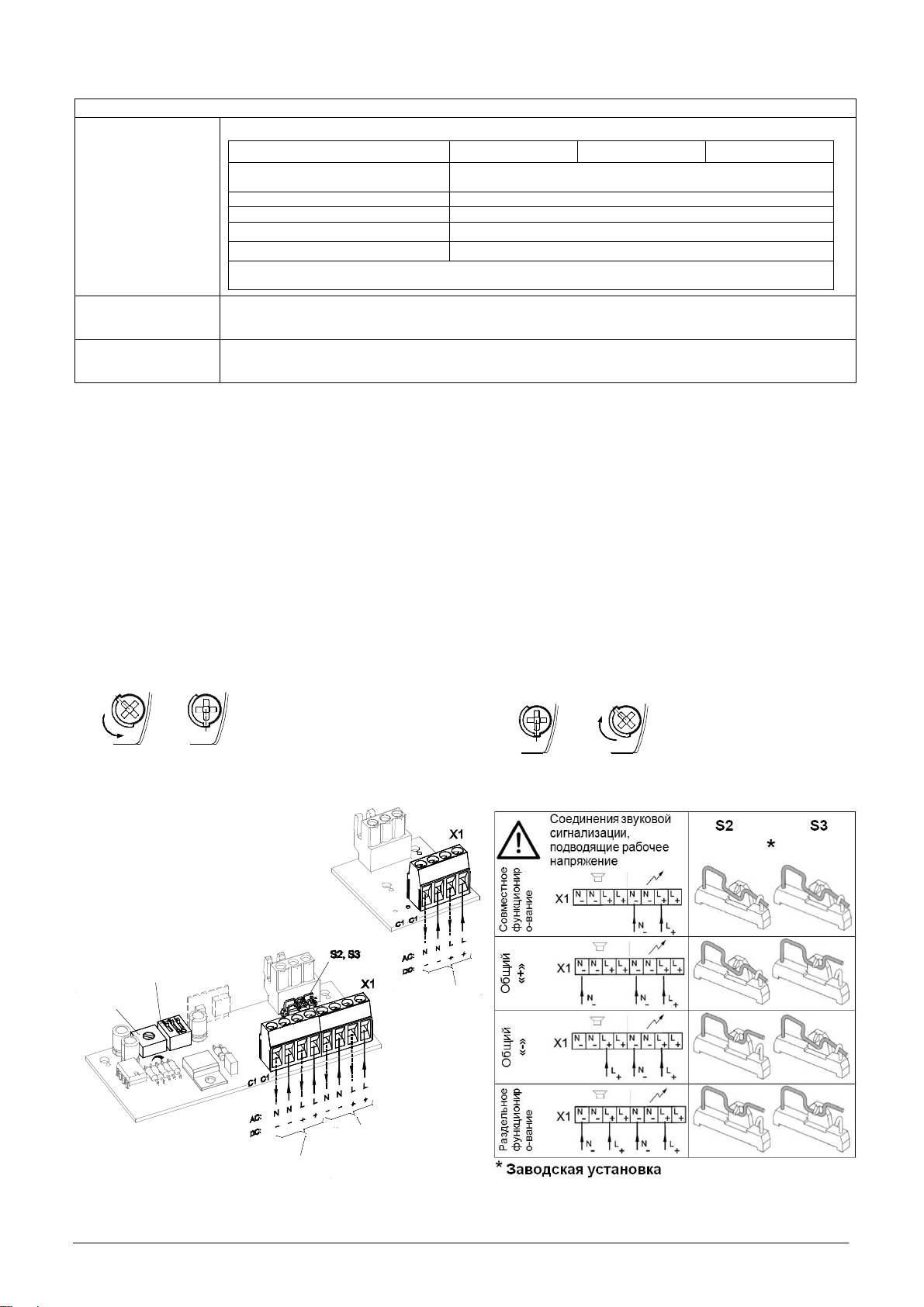
Подключение
рабочего
напряжения
Подключение рабочего
напряжения для
Подключение рабочего напряжения
световой сигнализации
для звукового оповещения
S1
Переключатель
тональности
Регулировка
звука
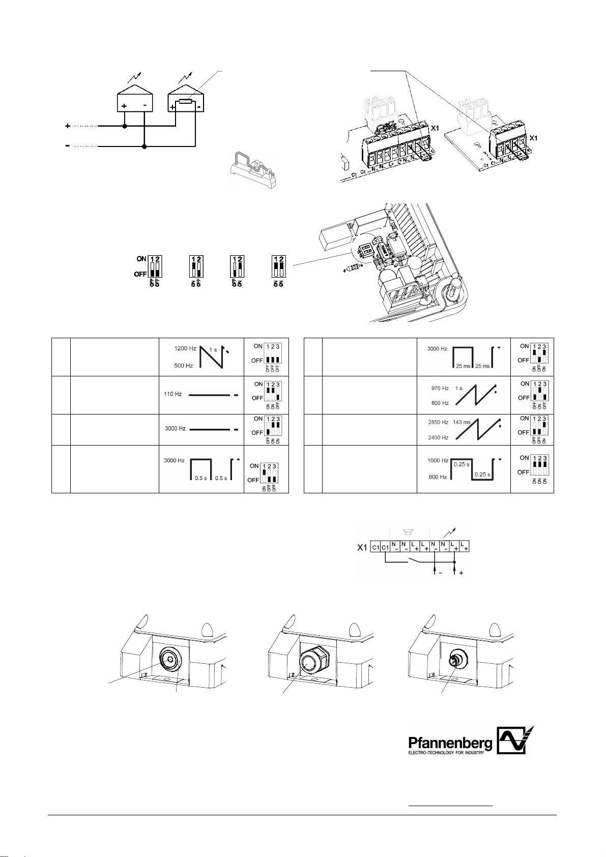
Резистор контроля цепи:
Einstellung der Blitzfrequenz
:
*
*
Заводская
установка
Einstellung der Tonarten:
Звук
пилы
DIN 33404-3
1
5
Сигнал
с
прерыванием
(
аварийный
сигнал
)
PFEER PTAP
085 501 972 30360-004 12
Сигнал
с
постоянной
2
тональностью
(
рупор
)
Пожарный
сигнал
с
повышением
6
тональности
UK BS5839-1
Сигнал
с
постоянной
3
тональностью
Сигнал
с
повышением
7
тональности
Сигнал
с
4
прерыванием
*
Сигнал
с
меняющейся
тональностью
8
UK BS5839-1,
пожарный
сигнал
,
ж
/
д
переезд
Элемент сопротивления для контроля
цепи
(1 кОм) на соединении рабочего
напряжения.
Позиция элемента сопротивления при
параллельном подключении нескольких
огней к последнему устройству.
Лишнее сопротивление удалить.
PY X-MA-xx PY X-M-xx
Плата
в
корпусе
*
Заводская установка, переключатель тональности S1 на плате, в нижней части, см. раздел «Подключение
электропитания».
Огни с входом управления (для PY X-M-xx)
В этом случае сигнальные огни активируются управляющим
напряжением. Потребление входа управления – макс. 1 Вт.
Кабельный ввод
Для сохранения имеющегося класса защиты в предусмотренные отверстия должны быть установлены кабельные
вводы класса IP 66. Поставляемый мембранный ниппель можно заменить резьбовой втулкой или штекерным
соединением М12 с фланцем М20.
После монтажа кабеля
удалить остатки мембраны.
Мембранный ниппель
Резьбовая втулка IP66 Штекерное соединение М12 IP66
IP66 (прилагается)
(для устройств малого напряжения
Техническое обслуживание и поддержание в исправном состоянии
Для данного устройства специальное техническое обслуживание не требуется. Очистка
наружных поверхностей осуществляется с помощью слабого мыльного раствора без
использования растворителей.
Разрешается использовать устройство только в неповреждённом состоянии, согласно
Pfannenberg GmbH
техническим характеристикам. При изменении конструкции, модификации
Werner-Witt-Straße 1
·
D- 21035 Hamburg
оборудования, его неправильном использовании и использовании не по назначению,
Tel.: +49/ (0)40/ 734 12-0
а также при несоблюдении указаний данного руководства гарантия теряет свою силу.
Fax: +49/ (0)40/ 734 12-101
Разрешается использовать только оригинальные запасные части.
technical.support @pfannenberg.com
http://www.pfannenberg.com 0312014
Ремонт производится только на предприятии-изготовителе.
1 Гц 0,75 Гц 0,5 Гц 0,1 Гц
При контроле цепи с использованием изменения
полюсов напряжения требуется активировать диод
для защиты от неправильной полярности с
разомкнутым выключателем S4 (на плате в
корпусе).
S4
*
Заводская
установка
