Pfannenberg PATROL PA 10 Series: инструкция
Раздел: Безопасность
Тип:
Инструкция к Pfannenberg PATROL PA 10 Series
PA 10/20 PA X 10-10/ PA X 10-15 PA X 20-10/ PA X 20-15
Betriebs- und Montageanleitung
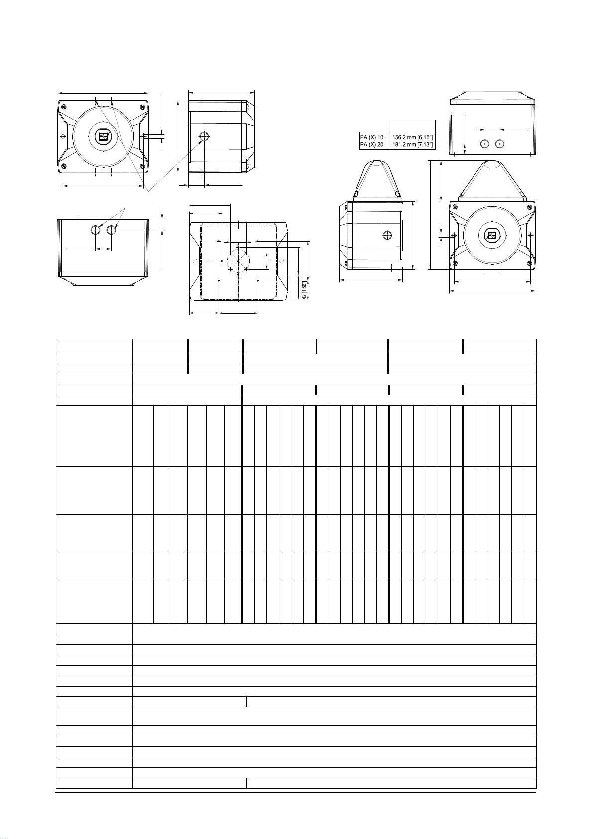
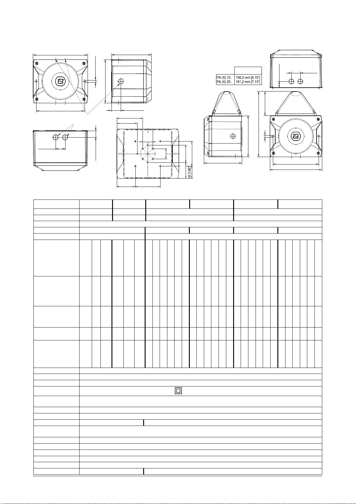
Maße
Technische Daten
PA 10 PA 20 PA X 10-10 PA X 10-15 PA X 20-10 PA X 20-15
Nennschallpegel 110dB (A) 1m
085 501 946j 30305-004j 1
120dB (A) 1m
110dB (A) 1m 120dB (A) 1m
Lautstärkeregelung -10dB -9dB -10dB -9dB
Töne 80
Blitzenergie - 10J 15J 10J 15J
Blitzfolgefrequenz - 1Hz
Bemessungs-
Spannung
(Begrenzungen
siehe Zulassungen)
24 V DC oder
24V AC
12-48V DC
110
–
240 V AC
50/60 Hz
24 V DC
oder
12
-
48V DC
24V AC
110
–
240 V AC
50/60 Hz
12V DC
24V DC
48V DC
24V AC
115V AC
230V AC
12V DC
24V DC
48V DC
24V AC
115V AC
230V AC
12V DC
24V DC
48V DC
24V AC
115V AC
230V AC
12V DC
24V DC
48V DC
24V AC
115V AC
230V AC
Spannungsbereich
10 – 60 V
20 – 30V
95 - 265 V
10 – 60 V
20 – 30V
95 – 265V
10,5 – 15 V
18V – 30V
40V – 60V
20 – 30V
95V – 127V
195V – 253V
10,5 – 15 V
18V – 30V
40V – 60V
20 – 30V
95V – 127V
195V – 253V
10,5 – 15 V
18V – 30V
40V – 60V
20 – 30V
95V – 127V
195V – 253V
10,5 – 15 V
18V – 30V
40V – 60V
20 – 30V
95V – 127V
195V – 253V
Stromaufnahme
Schallgeber (max.)
[mA]
24V: 360
485
850
140
24V: 800
880
1600
330
490
360
230
850
150
100
490
360
230
850
150
100
460
800
500
1600
330
200
460
800
500
1600
330
200
Stromaufnahme
Blitzleuchte (max.)
–
–
–
–
–
–
1400
[mA]
680
300
1400
300
160
1550
850
440
1400
330
220
1400
680
300
1400
300
160
1550
850
440
1400
330
220
Leistungsaufnahme
24V: 8,5 W
12-48V: 9W
17,5 VA
15,5 VA
24V: 24,5 W
12-48V: 27W
Kartoninhalt:
214 [8.44"]
L
1x Alarmgerät
1x Membrannippel M20
1x Betriebsanleitung
1x Widerstand (nur –SSM)
Ø9 [0.35"]
L
37 [1.46"]
26 [1.02"]
170 [6.69"]
190 [7.48"]
37 [1.46"]
100 [3.94"]
M20-Ausbruch vorbereitet/
Bohrbild im Inneren
Prepared M20 cut-out
89.4 [3.52"]
70.7 [2.78"]
des Gehäuses
270 [10.63"]
35.4
[1.39"]
37 [1.46"]
170 [6.69"]
Ø9 [0.35"]
26 [1.02"]
35.4
[1.39"]
60 [2.36"]
86 [3.39"]
L
190 [7.48"]
214 [8.44"]
55 [2.17"]
PA 10/ PA 20
64.2 [2.53"]
86 [3.39"]
50 VA
22 W
22 W
32 W
29 W
57 VA
45 VA
38 W
80 VA
72 VA
35 W
51 W
97 VA
17,5 VA
54,5 VA
34,5 VA
40,5 VA
27,5 W
32,5 W
65,5 VA
27,5 W
50,5 W
62,5 VA
43,5 W
82,5 VA
72,5 VA
Einschaltdauer 100%
Anschlussklemmen 0,14 - 2,5mm² feindrähtig / AWG24 - AWG 14 (stranded)
Schutzart IP66 (EN60529), Type 4 & 4x
Schutzklasse II
Betriebstemperatur -40°C…+55°C
Lagertemperatur -40°C…+70°C
Max. rel.Luftfeuchte 90%
Kabeleinführung 7x M20 vorgeprägt 5x M20 vorgeprägt
Dichtbereich der
7 – 13 mm Bei Verwendung von Kabeldurchmessern < 7 mm ist eine Kabelverschraubung
Durchführungstülle
mit ausreichender Schutzart vorzusehen
Gehäusematerial PC/ABS Blend
Haubenmaterial PC
Einbaulage beliebig
Optionen -SSM, (siehe Seite 5)
Zubehör Plombierstopfen (Art-Nr. 28300000002)
Haubenfarben
- klar, weiß, gelb, orange, rot, grün, blau
PA X 10
-
10/ PA X 10
-
15
PA X 20-10/ PA X 20-15
Zulassungen
Zulassungen
(gilt für gekennzeichnete Betriebsmittel)
Bauproduktenrichtlinie
PA10/ PA 20, 110-230V AC: PA10/ PA 20, 24-48V DC: PA10-SSM, PA 20-SSM:
(89/106/EWG)
VdS 0786-CPD- 21184 VdS 0786-CPD- 21223 0786-CPD- 21224
085 501 946j 30305-004j 2
PA 10/ PA 20
Optionen –SSM
Bemessungsspannung 24 -48 V DC 110V – 240V AC
Spannungsbereich
18V – 60V
95V – 265V AC
gemäß EN54-3
Option: -SSM: 18V – 30V
Ton
konform zur Bauproduktenrichtlinie (89/106/EWG)
2
1200Hz-500Hz (Sägezahn/ Saw tooth) DIN/PFEER P.T.A.P.
15
500Hz-1200Hz (Ansteigender Ton/ Slow whoop)
60
825Hz (Dauerton/ Continuous)
104
660Hz (Unterbrochener Ton/ Intermittent)
131
800Hz/ 1000Hz (Wechselton/ Alternating)
146
544Hz/ 440Hz (NF S 32-001)
EN54-3: siehe Dokumente
Signalisierungsbereich
30305-005-1 (PA 10) und 30306-005-1 (PA 20)
Umweltschutzklasse Typ B
Die Prüfung erfolgte unter Verwendung des mitgelieferten Membrannippels und der äußeren Be-
festigungsbohrungen.
PA10/ PA 20, 110 – 230V AC: PA10/ PA 20, 24 - 48V DC: PA10-SSM, PA 20-SSM:
VdS
G212116 G212191 G212192
Daten siehe Bauproduktenrichtlinie (89/106/EWG)
GLxxxxx (in Vorbereitung)
GL
Umweltkategorie C, H, EMC1
UL, cUL UCST, UCST7, ULSZ, ULSZ7, UEES, UEES7 (weiterführende Informationen siehe Seite 7)
Inbetriebnahme
Sicherheitshinweise:
- Der elektrische Anschluss darf nur von hierfür autorisierten Personen in Übereinstimmung mit den derzeit gültigen
Vorschriften durchgeführt werden.
- Warnung vor gefährlicher hoher elektrischer Spannung.
- Vor dem Öffnen ist sicherzustellen, dass das Gerät nicht unter Spannung steht.
- Vor Inbetriebnahme ist die auf dem Typenschild angegebene Versorgungsspannung zu kontrollieren. Eine falsche
Betriebsspannung kann zur Schädigung bzw. zur Zerstörung des Betriebsmittels führen.
- Bei der Installation ist darauf zu achten, dass die Anschlussleitung gegen Zug und Verdrehen abgesichert ist. Bitte
beachten: Die Geräte sind nicht für einen ortsveränderlichen Einsatz bestimmt.
- WARNUNG: Bei Installation Verdrahtung entfernt von scharfen Kanten, Ecken und internen Komponenten.
- Die Öffnung des Schalltrichters darf insbesondere bei Verwendung im Außenbereich oder in staubreicher Umgebung
nicht nach oben zeigen.
- Die Funktion des Gerätes ist nur gewährleistet, wenn Ober- und Unterteil korrekt zusammengefügt sind.
Bei Verwendung der Kombination mit der Leuchte (PA X 10-10; PA X 10-15; PA X 20-10; PA X 20-15):
- Um eine Beeinträchtigung des Sehvermögens zu verhindern, ist der dauernde, direkte Blick in die aktivierte Leuchte zu
vermeiden.
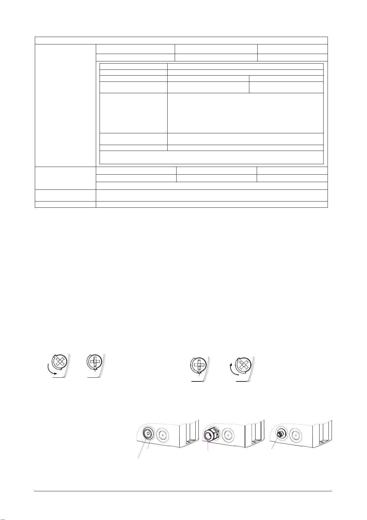
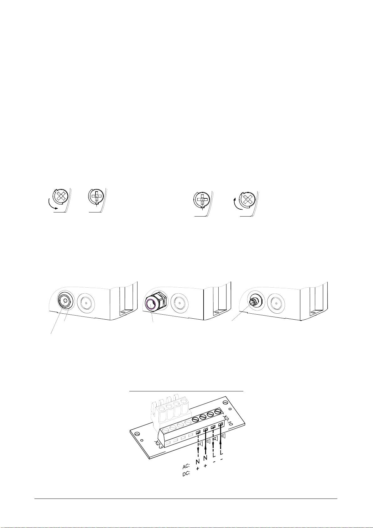
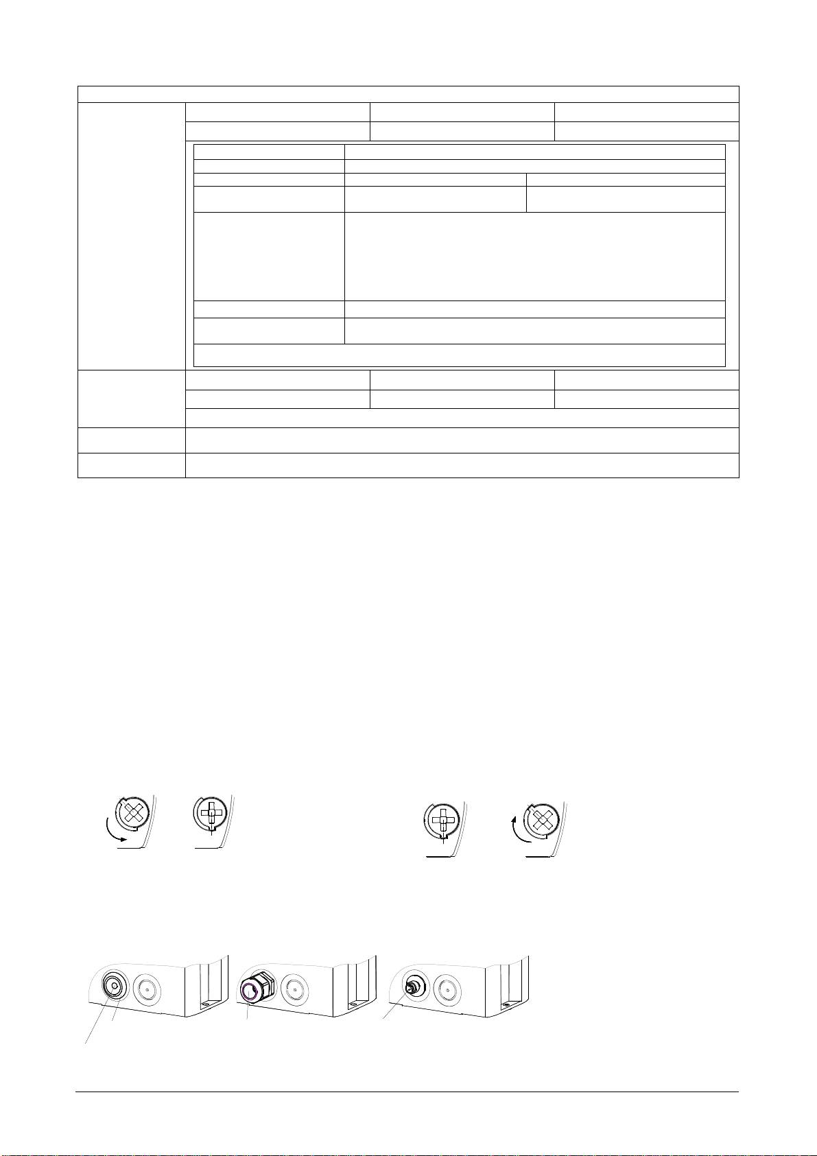
Öffnen des Gehäuses: Verschließen des Gehäuses
1. 2.
1. 2.
Verschließen des Gehäuses
Durch Lösen der vier
durch Drehen der Deckel-
Deckelschrauben lässt
sich das Oberteil ab-
3/8
nehmen:
3/8
Das Gerät wird in nicht verschlossenem Zustand ausgeliefert.
Plombierstopfen für die Gehäuseschrauben sind als Zubehör erhältlich.
Kabeldurchführungen
Zur Sicherstellung der angegebenen
Schutzart sind an den dafür vorgesehenen
Durchbrüchen Kabeldurchführungen mit
einer Schutzart von IP 66 zu montieren.
Der mitgelieferte Membrannippel kann
durch eine Kabelverschraubung oder
durch einen M12-Steckverbinder mit ei-
nem Flanschmaß von M20 ersetzt wer-
den.
schrauben in die Endstellung
bis zur Verrastung.
Membrannippel IP 66
Kabelverschraubung
M12- Steckverbinder IP 66
(mitgeliefert)
IP 66
(für Low Voltage -Geräte)
Nach Montage des Kabels
Reste der Membrane entfernen.
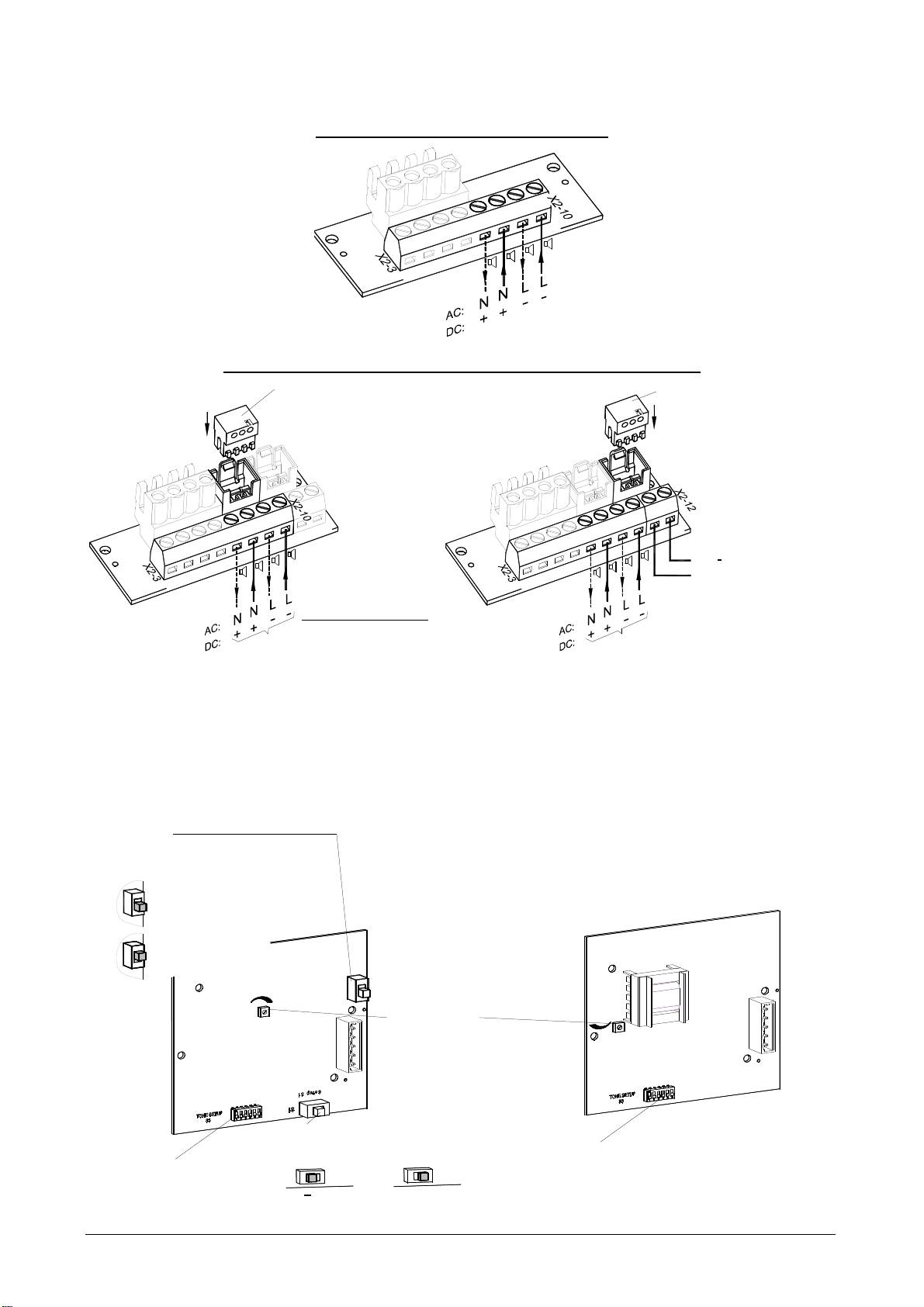
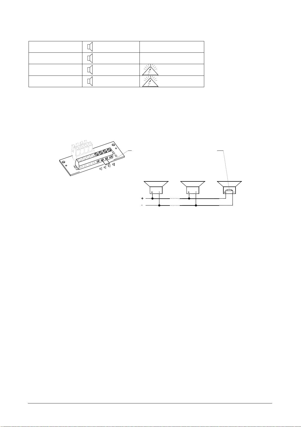
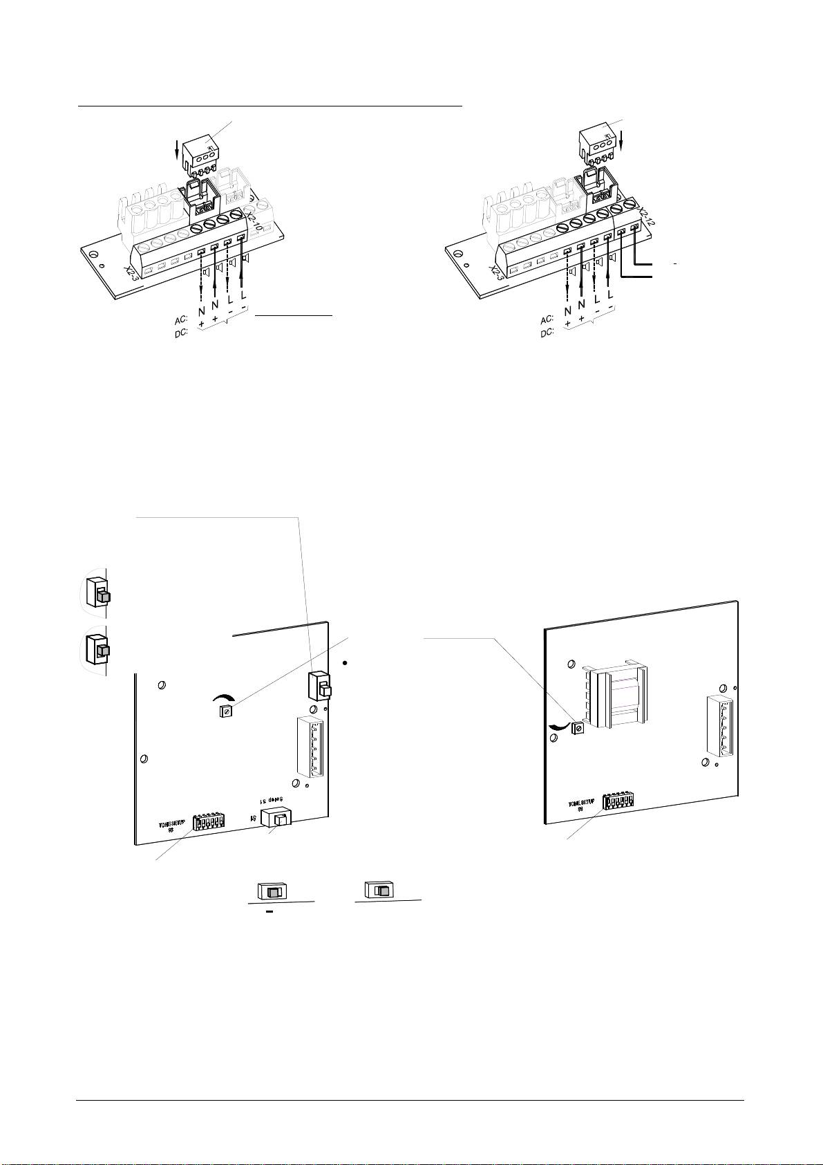
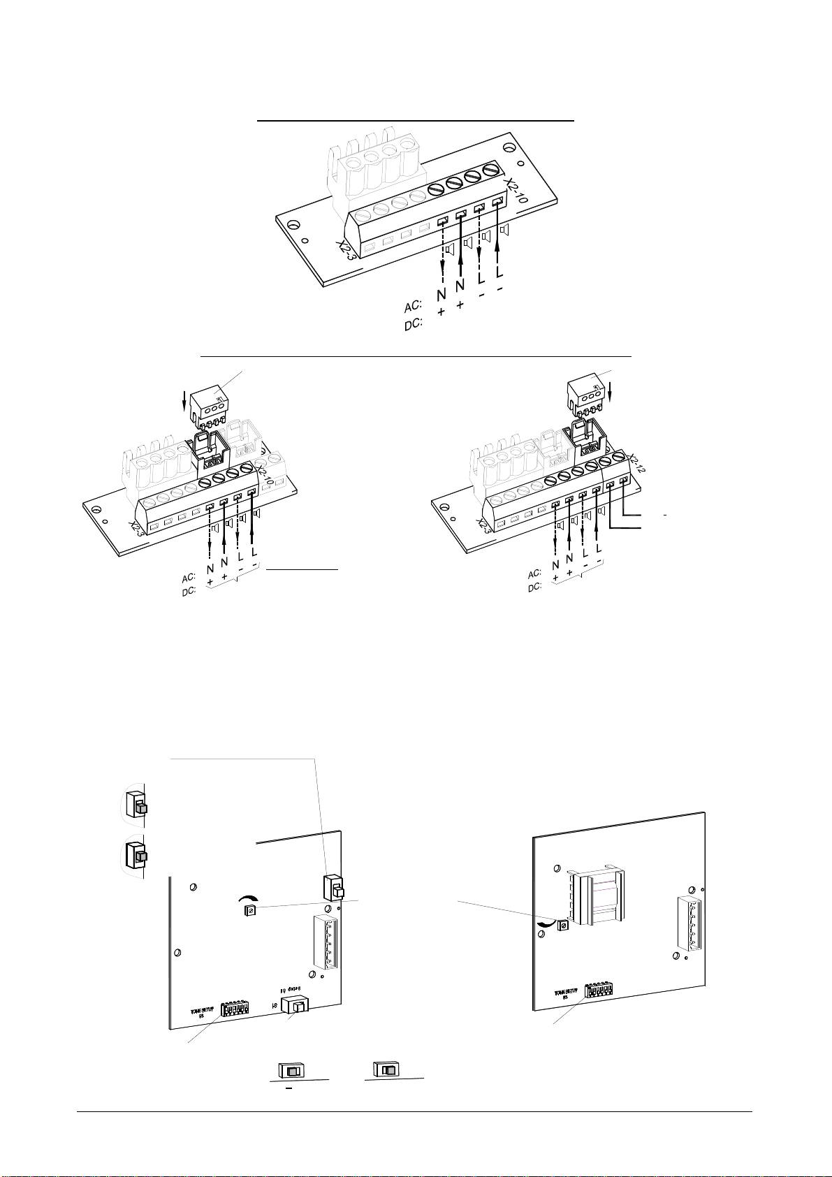
Anschlussplatine im Unterteil:
Elektrischer Anschluss und Tonauswahl durch externe Ansteuerung C1 und C2
Betriebsspannungsanschluss Schallgeber:
-L
-L
+N
+N
C1
C1
X2
C2
C2
Betriebsspannungs-
anschluss
Betriebsspannungsanschluss Schallgeber-Blitzleuchten-Kombination:
Stecker von der Blitzleuchtenplatine
Stecker von der Blitzleuchtenplatine
X3
X4
X3
X4
-L
-L
+N
+N
-L
-L
Betriebsspannungs-
-L
-L
+N
+N
anschluss für Blitzleuchte:
+N
+N
C1
C1
L
C1
C1
C2
C2
N
+
X2
C2
X2
C2
AC:
DC:
Schallgeber und Blitzleuchte
Betriebsspannungs-
anschluss
Betriebsspannungs-
anschluss für Schallgeber
Gemeinsamer Anschluss von getrennter Anschluss von
Blitzleuchte und Schallgeber Blitzleuchte und Schallgeber
(Auslieferungszustand)
Der gewünschte Ton kann mithilfe des Tonartenschalters S3 (auf der Treiberplatine im Oberteil) ausgewählt wer-
den. Die möglichen Töne sind in der Tonartentabelle im Anhang beschrieben.
Nach Anlegen der Versorgungsspannung wird der Ton erzeugt.
Schallgeber-Treiberplatine (im Oberteil):
S2
(Überbrückung
Verpolungsschutzdiode)
mit Verpolungsschutz
DC
AC
(with rectifier)
Werkseinstellung
ohne Verpolungsschutz
(without rectifier)
S2
-
+
Lautstärkeregler
+
-
Hinweis:
Um EN54-3 konform zu sein, muss sich
der Lautstärkeregler in der
folgenden Position befinden:
PA 10: in Maximalposition
S3
S3
PA 20: in der werksmäßig eingestellten
und gesicherten Position
S1
(Auswahl der Polarität der
Tonartenschalter
Steuerspannung für C1 und C2)
Tonartenschalter
+
Werkseinstellung
085 501 946j 30305-004j 3
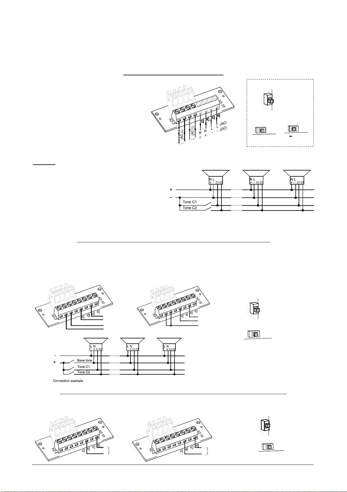
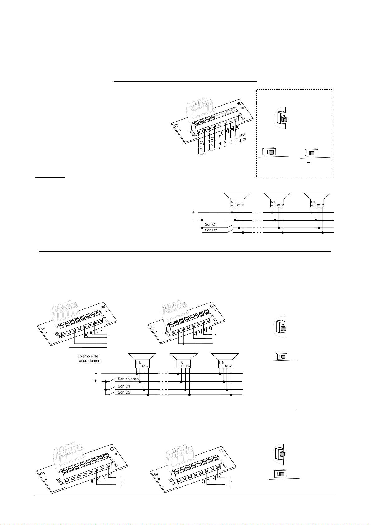
Änderung der Töne durch externe Ansteuerung
Für Anwendungen, die zusätzlich zum Grundton weitere Töne benötigen, besteht die Möglichkeit, bis zu drei wei-
tere Tonarten mithilfe der folgenden elektrischen Ansteuerungen zu erreichen.
Grundsätzlich wird erst der gewünschte Grundton ♪ (siehe Tonartentabelle im Anhang) mit dem Tonartenschalter
S3 auf der Treiberplatine eingestellt. Die korrespondierenden zusätzlichen Töne (C1, C2, C1+C2) sind der Tabelle
„Ansteuerung der Töne“ im Anhang zu entnehmen.
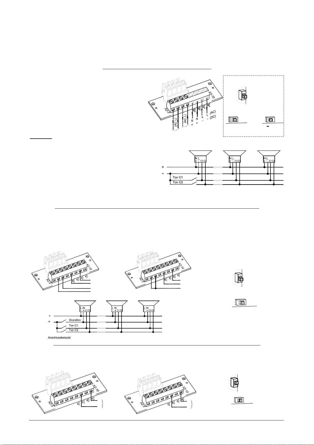
Tonstufenauswahl durch Steuereingang (TAS)
DC-Version:
Bei polrichtiger Anwendung erfolgt die Tonauswahl über
DC-Version
die Steuereingänge C1 und C2 auf der Anschlussplatine.
Die Versorgungsspannung muss dabei immer zusam-
men mit den Steuereingängen angelegt werden. Schalter
S2 auf der Treiberplatine ist in der Stellung mit
-L
-L
+N
+N
Verpolungsschutz (with rectifier).
C1
C1
C2
Über den Schalter S1 auf der Treiberplatine erfolgt die
X2
C2
bzw.
S1
S1
Auswahl der Polarität der Steuerspannung („+“ oder „–“).
„+“: positive Ansteuerung
+
Ton C1
positive
negative
„-„: negative Ansteuerung (Werkseinstellung)
Ton C2
Achtung: Ist die Steuerspannung größer als die Versor-
gungsspannung oder die Versorgungsspannung liegt nicht
an, erfolgt die Betriebsstromversorgung über die Steuer-
eingänge. Eine entsprechende Belastbarkeit muss dann
gewährleistet sein.
AC-Version:
In der AC-Version erfolgt die Tonauswahl durch Anschlie-
ßen der Phase „L“ der Versorgungsspannung an die Steu-
ereingänge C1 bzw. C2.
Die Versorgungsspannung muss dabei immer zusammen
Beispiel für DC “–“ -
mit den Steuereingängen angelegt werden.
Tonstufenauswahl durch Versorgung über Steuereingang (TAV) - für alle DC-Versionen
Der Schallgeber kann über die Steuereingänge C1 bzw. C2 auf der Anschlussplatine mit Betriebsspannung ver-
sorgt werden. Versorgung und Tonstufenauswahl erfolgt somit gleichzeitig.
Der Minuspol des Schallgebers muss angeschlossen sein.Durch Anschließen der positiven Spannung an den
Pluspol der Anschlussplatine wird der Grundton (♪) erzeugt; durch Anschluss an C1 bzw. C2 wird die entspre-
chende Tonstufe ausgewählt.
Durch gleichzeitiges Anschließen der positiven Spannung an C1 und C2 wird die Tonstufe „C1+C2“ gewählt.
Der Schalter S1 auf der Treiberplatine muss auf „+“ stehen.
-L
-L
-L
-L
+N
+N
+N
+N
C1
C1
C1
-
C1
C2
-
X2
C2
+
Grundton
X2
C2
Grundton
C2
+
+
Ton C1
+
Ton "C1+C2"
+
Ton C2
S1
+
positive
Tonstufenauswahl durch Verpolung (TAR) - für alle DC-Versionen (außer Option –SSM)
Steht der Schalter S2 auf der Treiberplatine in der Stellung „ohne Verpolungsschutz = without rectifier“, kann durch
Verpolung der Betriebsspannung zum Grundton (♪) zusätzlich Ton „C1+C2“ gewählt werden. Der Umschalter S1
muss auf „+“ geschaltet werden. Die Steuereingänge C1 und C2 dürfen auf der Anschlussplatine nicht beschaltet
werden.
-L
-L
-L
+N
-L
S1
+N
+N
C1
-
+N
C1
Grundton
C1
+
C2
C1
Ton "C1+C2"
X2
C2
+
C2
X2
C2
-
+
positive
085 501 946j 30305-004j 4
Ansteuerung
mit Verpolungsschutz
(with rectifier)
S2
Werkseinstellung
mit Verpolungsschutz
(with rectifier)
S2
Werkseinstellung
S2
ohne Verpolungsschutz
(without rectifier)
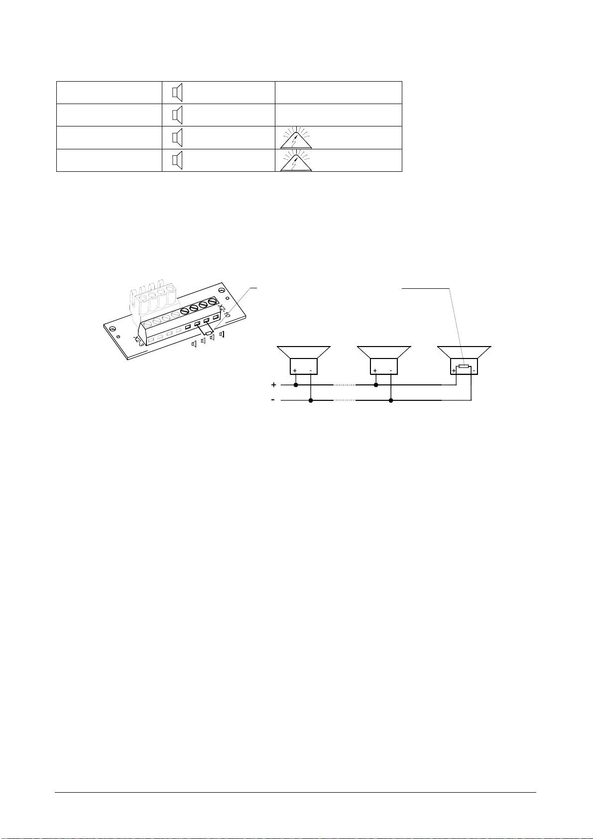
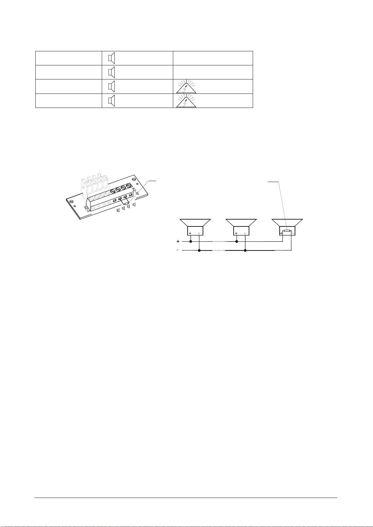
Option –SSM (Soft-Start-Modul) (nur 24V DC):
Begrenzung der Einschaltstromspitze auf:
PA 10-SSM:
085 501 946j 30305-004j 5
: max. 2,1 A
PA 20-SSM:
: max. 4,5 A
PA X 10-xx-SSM:
: max. 2,1 A
: max. 4,5 A
PA X 20-xx-SSM:
: max. 4,5 A
: max. 4,5 A
- Durchschalten der Betriebsspannung zum Betriebsmittel erst ab >7V
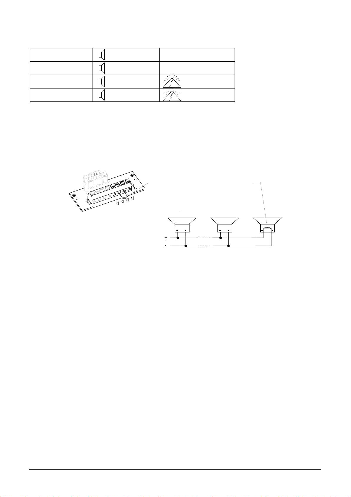
- Widerstand zur Leitungsüberwachung angeschlossen
Betriebsspannungsbereich: 18V – 30V DC
Widerstand zur Leitungsüberwachung:
Widerstand für Leitungsüberwachung (1KOhm)
am Betriebsspannungsanschluss.
-L
-L
Position des Widerstandes bei Parallelschaltung
+N
+N
C1
C1
von mehreren Schallgebern im letzten Gerät.
X2
C2
C2
nicht benötigte Widerstände entfernen
Wartung, Service, Instandhaltung
Das Gerät erfordert keine besondere Wartung. Die äußere Reinigung sollte mit einer schwachen Seifenlösung
ohne Verwendung von Lösungsmittel erfolgen.
Der Schallgeber darf nur in unbeschädigtem Zustand innerhalb der spezifizierten Kenndaten betrieben werden.
Umbauten, Änderungen, fehlerhafter und unzulässiger Einsatz sowie die Nichtbeachtung der Hinweise dieser
Betriebsanleitung schließen eine Gewährleistung aus.
Ein Austausch von Komponenten darf nur mit Originalersatzteilen erfolgen. Reparaturen sind grundsätzlich im
Herstellerwerk auszuführen.
PA 10/20 PA X 10-10/ PA X 10-15 PA X 20-10/ PA X 20-15
Operating and installation instruction
Dimensions
PA 10/ PA 20 PA X 10-10/ PA X 10-15
PA X 20-10/ PA X 20-15
Technical Data
PA 10 PA 20 PA X 10-10 PA X 10-15 PA X 20-10 PA X 20-15
Nom. sound level
110dB (A) 1m
085 501 946j 30305-004j 6
120dB (A) 1m
110dB (A) 1m 120dB (A) 1m
Volume control
-10dB -9dB -10dB -9dB
Tones
80
Flash energy
- 10J 15J 10J 15J
Flash frequency
- 1Hz
Rated voltage
(limits see approvals)
24V AC
24 V DC or
12-48V DC
110
–
240
V AC
50/60 Hz
24 V DC oder
12
-
48
V DC
24V AC
110
–
240
V AC
50/60 Hz
12V DC
24V DC
48V DC
24V AC
115V AC
230V AC
12V DC
24V DC
48V DC
24V AC
115V AC
230V AC
12V DC
24V DC
48V DC
24V AC
115V AC
230V AC
12V DC
24V DC
48V DC
24V AC
115V AC
230V AC
Operating voltage
range
10 – 60 V DC
20 – 30V AC
95
-
265 V
AC
10 – 60 V DC
20 – 30V AC
95 - 265 AC
10,5 – 15 V
18V – 30V
40V – 60V
20 – 30V
95V – 127V
195V –
253V
10,5 – 15 V
18V – 30V
40V – 60V
20 – 30V
95V – 127V
195V –
253V
10,5 – 15 V
18V – 30V
40V – 60V
20 – 30V
95V – 127V
195V –
253V
10,5 – 15 V
18V – 30V
40V – 60V
20 – 30V
95V – 127V
195V –
253V
Current
consumption
Sounder (max.) [mA]
24V: 360
485
850
140
24V: 800
880
1600
330
490
360
230
850
150
100
490
360
230
850
150
100
460
800
500
1600
330
200
460
800
500
1600
330
200
Current consumption
Beacon (max.) [mA]
–
–
–
–
–
–
1400
680
300
1400
300
160
1550
850
440
1400
330
220
1400
680
300
1400
300
160
1550
850
440
1400
330
220
Power consumption
24V: 8,5 W
12-48V: 9W
17,5 VA
15,5 VA
24V: 24,5 W
12-48V: 27W
50 VA
22 W
22 W
32 W
29 W
57 VA
45 VA
38 W
80 VA
72 VA
35 W
51 W
97 VA
17,5 VA
54,5 VA
34,5 VA
40,5 VA
27,5 W
32,5 W
65,5 VA
27,5 W
50,5 W
62,5 VA
43,5 W
82,5 VA
72,5 VA
Duty cycle 100%
Connection terminal 0,14 - 2,5mm² / AWG24 - AWG 14 (stranded)
Ingress protection IP66 (EN60529), Type 4 & 4x
Protection class
II Double insulated equipment
Operating
-40°C…+55°C
temperature
Storage temperature
Content of package:
214 [8.44"]
L
1x Alarm device
1x Diaphragm nipple M20
1x Operating instruction
1x Resistor (only –SSM)
L
37 [1.46"]
Ø9 [0.35"]
26 [1.02"]
170 [6.69"]
190 [7.48"]
37 [1.46"]
100 [3.94"]
M20-Ausbruch vorbereitet/
Prepared M20 cut-out
270 [10.63"]
170 [6.69"]
Ø9 [0.35"]
37 [1.46"]
35.4
26 [1.02"]
[1.39"]
L
190 [7.48"]
214 [8.44"]
-40°C…+70°C
Max. rel. Humidity 90%
Cable entry 7x M20 (prepared) 5x M20 (prepared)
Sealing range of
7 – 13 mm
grommet
With the use of cable diameters <7mm, a cable screw joint with sufficient ingress protection must be provided
Material of housing PC/ABS Blend
Material of lens PC
Installation position arbitrarily
Options -SSM, (see page 11)
Accessory Sealing plug (Art-no. 28300000002)
Lens colours
- clear, white, yellow, amber, red, green, blue
89.4 [3.52"]
Hole pattern in the
70.7 [2.78"]
inside of housing
35.4
[1.39"]
60 [2.36"]
86 [3.39"]
55 [2.17"]
64.2 [2.53"]
86 [3.39"]
Approvals
(valid for marked equipment)
Construction
PA10/ PA 20, 110-230V AC: PA10/ PA 20, 24-48V DC: PA10-SSM, PA 20-SSM:
Product Directive
VdS 0786-CPD- 21184 VdS 0786-CPD- 21223 0786-CPD- 21224
(89/106/EWG)
085 501 946j 30305-004j 7
PA 10/ PA 20
Options –SSM
Rated voltage 24 – 48 V DC 110V – 240V AC
Operating voltage range acc.
18V – 60V
95V – 265V AC
to EN54-3, EN54-23
Option: -SSM (18V – 30V)
Tone
Compliant with the Construction Product Directive (89/106/EWG)
2
1200Hz-500Hz (Saw tooth) DIN/PFEER P.T.A.P.
15
500Hz-1200Hz (Slow whoop)
60
825Hz (Continuous)
104
660Hz (Intermittent tone)
131
800Hz/ 1000Hz (Alternating tone)
146
544Hz/ 440Hz (NF S 32-001)
Signaling area EN54-3: see documents 30305-005-1
(PA 10)
and 30306-005-1
(PA 20)
Environmental protection class Type B
The test was performed using the provided diaphragm nipples and the outer fixing holes.
PA10 / PA 20, 110 – 230V AC: PA10/ PA 20, 24 - 48V DC: PA10-SSM, PA 20-SSM:
VdS
G212116 G212191 G212192
Data see Construction Product Directive (89/106/EWG)
GL GLxxxxx (in preparation) Environmental Category C, H, EMC1
Audible Signal Appliance
Audible and Visual Signal Appliance
Rated voltage
Fire Alarm Equipment
General Signal Equipment
ULSZ, ULSZ7
UCST, UCST7 and UEES, UEES7
24V – 48V DC
PA 10
(Fire Alarm Equipment)
PA 20
12V – 48V DC
(General Signal Equipment)
UL, cUL
x
Special application, limited operating
x
voltage range 18 – 60V DC
PA 10
24V AC
- x
PA 20
110 – 240V AC
115V AC
230V AC
PA X 10 ..
24V AC
- x
PA X 20 ..
12V DC
24V DC
48V DC
PATROL sounders and combined units PA 10/ PA 20/ PA X 10../ PA X 20.. comply with the limits for a Class B digital
device, pursuant to part 15 of the FCC Rules.
UL/ cUL specifications:
Inrush current
PA 10
, PA 20
Surge Current Peak
Surge Current RMS
(16,7ms frame)
Voltage
24 – 48 V DC 27 A 4,5 A 60 V DC
24 V AC 11,5 A 6,8 A 30 V AC
110 – 240 V AC 18,5 A 1,45 A 265 V AC
Suitable for indoor and outdoor use.
Signaling area: see document 30305-005-1 (PA 10) and 30306-005-1 (PA 20)
Cable gland entries:
Conduit installation needs to be UL/ cUL listed fittings suitable for knockout openings. The supply wiring has to be enclosed in metal
conduits for products for Fire Alarm Use.
Installation:
The units shall be installed indoors or outdoors in accordance with the manufacturer’s installation instructions as well as the National
Electrical Code (NFPA 70) and the National Fire Alarm Code (NFPA 72) for the units evaluated for Public Fire Alarm applications in the
U.S. In Canada, they shall be installed in accordance with the Canadian Electrical Code, Part 1 and the Standard for the Installation of
Fire Alarm Systems CAN/ULC-S524-M91 for the units evaluated for Public Fire Alarm applications. The installation shall also be in a
manner acceptable with the local authority having jurisdiction.
For audible application for Fire Alarm Service use both terminals for connection. Break wire run to provide Electrical Supervision (see
UL 464 clause 39.1e). The tone no. 111 is to be used for evacuation use only (see UL 464 clause 39.1e)
Volume control: PA 20/ PA X 20 ..: The volume control has to be set to the secured factory position.
cUL directional characteristics for
AXIS ANGLE dBA
the horn:
Horizontal 32 deg. left or right -3
Horizontal 28 deg. left or right -6
Vertical 32 deg. left or right -3
Vertical 28 deg. left or right -6
Min. Output sound pressure
Type Voltage UL 464 db(A) at 10 ft ++ CAN/ULc-S525-07
level: [dB(A)]
PA 10 (24-48 DC) 18V DC 82,4 (for tone 113) 92,4 (for tone 111)
(Tone no. 2, 15, 60, 104, 131, 146, 111,
112, and 113 was used for this test.)
PA 20 (24-48 DC) 18V DC 84,3 (for tone 113) 99,3 (for tone 111)
Connecting cables:
7 [0.28"]
7 [0.28"]
solid
stranded
Taking into operation
Safety notes:
- Installation must be carried out by an electrician in compliance with the latest codes and regulations.
- Danger: High voltage may be present.
- Prior to opening, it must be ensured that no voltage is applied to the device.
- Before electrical connection, the supply voltage on the type plate is to be checked. The wrong operating voltage
can lead to damages or to the destruction of the equipment.
- During installation it must be ensured that the connection cables are secured against tension and distortion.
Please observe: The devices are not designed for portable use.
- CAUTION: When making installation, route field wiring away from sharp projections, corners and internal compo-
nents.
- The opening of the bell mouth must not point upwards, especially in the case of use outdoors or in a particularly
dusty environment.
- The function of the unit is only guaranteed if the upper and lower section is joined correctly.
When using the sounder –beacon combination (PA X 10-10; PA X 10-15; PA X 20-10; PA X 20-15):
- In order to prevent detriment to sight, continuously looking directly in the activated light is to be avoided.
Opening the housing: Closing the housing
By loosing the four
1. 2.
1. 2.
3/8
3/8
The unit is not closed when delivered.
Sealing plugs for the housing screws are available as accessories.
Cable gland entries
To guarantee the specified protection type, cable grommets with a protection type of IP 66 are to be installed at
the openings provided for this purpose. The supplied diaphragm nipple can be replaced with a cable gland or with
an M12 plug connection with a flange measurement of M20.
Diaphragm nipple IP 66
Cable gland IP 66
M12 plug connector IP 66
(provided)
(for low voltage versions)
After pushing through the cable remove
the remaining membrane break-out.
Circuit board for electrical connection (located in the base section):
Electrical connection and tone selection using external control C1 and C2
Terminal for operating voltage - Sounder:
-L
-L
+N
+N
C1
C1
C2
X2
C2
Connection for
Operating voltage
085 501 946j 30305-004j 8
cover screws, the upper
section can be re-
moved.
The housing is closed
by turning the cover
screws to the limit
position until the
housing locks into
place.
Terminal for operating voltage - Sounder-beacon combination:
Plug from beacon circuit board
Plug from beacon circuit board
X3
X4
X3
X4
-L
-L
+N
+N
-L
-L
Operating voltage
-L
-L
+N
+N
for the beacon
+N
+N
C1
C1
L
C1
C1
C2
C2
C2
X2
C2
N
+
X2
AC:
DC:
Sounder and Beacon
Connection for
Operating voltage
Operating voltage
for the sounder
Common connection of Separate connection of
beacon and sounder beacon and sounder
(Delivery status)
The desired tone can be selected using the tone selector switch S3 (on the driver circuit board). The available
tones are described in the tone table in the appendix.
After establishing the supply voltage the tone is generated.
Driver circuit board of sounder (located in the upper section):
S2
(Bridging
of blocking diode)
with reverse polarity protection
DC
AC
(with rectifier)
Factory setting
Volume control
without reverse polarity protection
Note:
(without rectifier)
To be EN54-3 compliant, the volume
control has to be set to
S2
-
+
the following position:
PA 10: Maximum position
+
-
PA 20: in the secured
factory setting position
To be UL/cUL compliant, the volume
control for PA 20 and PA X 20..
S3
has to be set to the secured
S3
factory setting position
S1
Tone selector switch
(Selection of polarity of the
Tone selector switch
control voltage for C1 and C2)
+
Factory setting
085 501 946j 30305-004j 9
Change of the tones by external control
For applications which require more tones than just the base tone, it is possible to provide up to three additional
tone types with the use of the following electrical controls.
As a basic rule, the desired base tone (♪, see tone table in the appendix) is set with the tone selector switch S3 on
the driver board. The corresponding additional tones (C1, C2, C1+C2) can be gathered from the table "Selection of
the tones".
Tone selection with control input (TAS)
DC-Version:
DC-Version
When used with correct polarity, the tone selection
with reverse
takes place through the control inputs C1 and C2 on
polarity protection
the circuit board. In the process, the supply voltage
(with rectifier)
S2
must always be applied together with the two con-
Factory setting
trol inputs. Setting of switch S2 in position
-L
-L
+N
+N
“with rectifier”
C1
C1
or
X2
C2
= with reverse polarity protection.
C2
S1
S1
The selection of the polarity of the control voltage
("+" or "-") takes place with the switch S1 on the
+
negative
Tone C1
positive
driver board.
Tone C2
"+": positive control
"-": negative control (factory setting)
Caution: If the control voltage is greater than the sup-
ply voltage or the supply voltage is not applied, the
operating current supply is provided through the control
inputs. A corresponding load capacity must then be
guaranteed.
AC-version:
In the AC version the tone selection takes place by
connecting the phase "L" of the supply voltage to the
control inputs C1 and C2. In the process, the supply
Example for DC “–“ -control
voltage must always be applied together with the two
control inputs.
Tone selection with supply through control input (TAV) - for all DC versions
The sounder can be supplied with operating voltage through the control inputs C1 and C2 on the circuit board.
Supply and tone selection thus take place simultaneously.
The minus pole of the sounder must be connected. With connection of the positive voltage to the plus pole of the
circuit board, the base tone (♪) is generated; with connection to C1 or C2 the corresponding tone is selected.
With simultaneous connection of the positive voltage to C1 and C2 the tone "C1+C2" is selected.
The switch S1 on the driver board must be set to "+".
with reverse
polarity protection
-L
-L
-L
-L
+N
+N
(with rectifier)
+N
+N
S2
C1
C1
C1
-
C1
-
+
Base tone
Factory setting
X2
C2
X2
C2
C2
C2
Base tone
+
+
Tone C1
+
Tone "C1+C2"
+
Tone C2
S1
+
positive
Tone selection through pole reversal (TAR) - for all DC versions except for option -SSM
If the switch S2 on the driver board is in the position "without reverse polarity protection = without rectifier", the
tone "C1+C2" can be selected in addition to the base tone through pole reversal. The switch S1 must be set to "+".
The control inputs C1 and C2 may not be switched on the circuit board.
S2
without reverse
polarity protection
(without rectifier)
-L
-L
-L
+N
-L
+N
S1
+N
-
+N
C1
C1
C1
+
Base tone
C1
X2
C2
C2
C2
Tone "C1+C2"
+
X2
C2
-
+
positive
085 501 946j 30305-004j 10
Option –SSM (Soft-Start-Module) (24V DC only):
- Limitation of start-up peak:
PA 10-SSM:
085 501 946j 30305-004j 11
: max. 2,1 A
PA 20-SSM:
: max. 4,5 A
PA X 10-xx-SSM:
: max. 2,1 A
: max. 4,5 A
PA X 20-xx-SSM:
: max. 4,5 A
: max. 4,5 A
- Switching through the operating voltage to equipment: above 7V
- Resistor for line monitoring mounted
Operating voltage range: 18V – 30V DC
Connection of a resistor for line monitoring:
Resistor (1kOhm) for line monitoring
at terminal for operating voltage
Position of resistor in last sounder when
-L
using several sounders in parallel:
-L
+N
+N
C1
Remove resistors if not needed
C1
X2
C2
C2
Maintenance, Service and Ordering Spare Parts
The device does not require any special maintenance.
External cleaning should be done with a mild soap solution without the use of solvents.
The device may only be operated in the undamaged state within the specified rating.
Conversions, alterations, improper and inadmissible use as well as the non-observance of the notes in these op-
erating instructions shall render the warranty null and void.
Components may be replaced only by original spare parts.
As a matter of principle, repairs are to be carried out in the manufacturing works.
PA 10/20 PA X 10-10/ PA X 10-15 PA X 20-10/ PA X 20-15
Instructions d’utilisation et de montage
Dimensions
PA X 10-10/ PA X 10-15
PA 10/ PA 20 PA X 20-10/ PA X 20-15
Caractéristiques techniques
PA 10 PA 20 PA X 10-10 PA X 10-15 PA X 20-10 PA X 20-15
Niveau sonore nom.
085 501 946j 30305-004j 12
110dB (A) 1m
120dB (A) 1m
110dB (A) 1m 120dB (A) 1m
Réglage du volume
-10dB -9dB -10dB -9dB
Sons
80
Puissance lumineuse
- 10J 15J 10J 15J
Fréquence du flash
- 1Hz
Tension de service
(Limitations voir admis-
sions)
24 V CC ou
11-48V CC
24V CA
110
–
240
V
CA 50/60 Hz
24 V
CC
o
u
12-48V CC
24V CA
110
–
240
V
CA
50/60 Hz
12V CC
24V CC
48V CC
24V CA
115V CA
230V CA
12V CC
24V CC
48V CC
24V CA
115V CA
230V CA
12V CC
24V CC
48V CC
24V CA
115V CA
230V CA
12V CC
24V CC
48V CC
24V CA
115V CA
230V CA
Plage de la tension
de service
10–60V
20–30V
95–265V
10–60V
20–30V
95–265V
10,5–15V
18–30V
40–60V
20–30V
95–127V
195–
253V
10,5–15V
18–30V
40–60V
20–30V
95–127V
195–
253V
10,5–15V
18–30V
40–60V
20–30V
95–127V
195–
253V
10,5–15V
18–30V
40–60V
20–30V
95–127V
195–
253V
Courant nominal
admis par la sirène
(max.) [mA]
24V: 360
485
850
140
24V: 800
880
1600
330
490
360
230
850
150
100
490
360
230
850
150
100
460
800
500
1600
330
200
460
800
500
1600
330
200
Courant nominal
admis par le flash
(max.) [mA]
–
–
–
–
–
–
1400
680
300
1400
300
160
1550
850
440
1400
330
220
1400
680
300
1400
300
160
1550
850
440
1400
330
220
Puissance
24V: 8,5 W
12-48V: 9W
17,5 VA
15,5 VA
24V: 24,5 W
12-48V: 27W
50 VA
22 W
22 W
32 W
29 W
57 VA
45 VA
38 W
35 W
51 W
17,5 VA
54,5 VA
34,5 VA
40,5 VA
27,5 W
32,5 W
65,5 VA
27,5 W
50,5 W
80 VA
72 VA
62,5 VA
43,5 W
97 VA
82,5 VA
72,5 VA
Facteur de marche
100%
Bornes de connexion
0,14 - 2,5 mm² en fils de faible diamètre/ AWG24 - AWG 14 (stranded)
Type de protection IP66 (EN60529), Type 4 & 4x
Classe de protection
II
Temp. de service -40°C…+55°C
Temp. de stockage -40°C…+70°C
Humidité relative max.
90%
7x M20 avec empreinte
Entrée de câbles
5x M20 avec empreinte préalable
préalable
Zone d’intensité du
7 – 13 mm En cas d’utilisation de câbles de diamètre < 7 mm, un raccord de câble équipé d’un type de protec-
profilé de protection
tion suffisant sera à prévoir
Matériau du boîtier Mélange PC/ABS
Matériau du capot
PC
Position de montage
Contenu de l’emballage :
214 [8.44"]
L
1 alarme
1 raccord fileté à membrane M20
1 instruction d’utilisation
1 résistor (seulement –SSM)
Ø9 [0.35"]
L
37 [1.46"]
26 [1.02"]
170 [6.69"]
190 [7.48"]
37 [1.46"]
100 [3.94"]
M20-Ausbruch vorbereitet/
Encoche
89.4 [3.52"]
Points de fixation à
Prepared M20 cut-out
préparée pour le M20
70.7 [2.78"]
l'intérieur du boîtier
35.4
270 [10.63"]
[1.39"]
170 [6.69"]
Ø9 [0.35"]
37 [1.46"]
35.4
[1.39"]
60 [2.36"]
86 [3.39"]
26 [1.02"]
L
190 [7.48"]
214 [8.44"]
55 [2.17"]
64.2 [2.53"]
86 [3.39"]
quelconque
Options -SSM (voir page 16)
Accessoires
Bouchon de plombier (art. n° 28300000002)
Couleurs du capot
- transparent, blanc, jaune, orange, rouge, vert, bleu
Admissions
Admissions
(valable pour les appareils signalés)
Directive sur les
PA10/ PA 20, 110-230V AC: PA10/ PA 20, 24-48V DC: PA10-SSM, PA 20-SSM:
produits de
construction
VdS 0786-CPD- 21184 VdS 0786-CPD- 21223 0786-CPD- 21224
(89/106/CEE)
085 501 946j 30305-004j 13
PA 10/ PA 20
Options - SSM
Tension de service 24 – 48 V CC 110V – 240V CA
Plage de tension de service
18V – 60V
95V – 265V CA
selon EN 54-3
Option: -SSM (18V – 30V)
Son
Conforme à la Directive sur les produits de construction (89/106/CEE)
2
1200Hz-500Hz (dent de scie DIN/PFEER P.T.A.P.
15
500Hz-1200Hz (son montant)
60
825Hz (son continu)
104
660Hz (son interrompu)
131
800Hz/ 1000Hz (son variable)
146
544Hz/ 440Hz (NF S 32-001)
Plage de signalisation EN54-3: Voir les documents 30305-005-1(PA 10) et 30306-005-1 (PA 20)
Classe de protection
Type B
environnementale
Le test a été effectué en utilisant le raccord fileté de membrane livré et les perçages extérieurs de fixation.
PA10 / PA 20, 110 – 230V AC: PA10/ PA 20, 24 - 48V DC: PA10-SSM, PA 20-SSM:
VdS
G212116 G212191 G212192
Pour les caractéristiques voir la Directive sur les Produits de construction (89/106/CEE)
GLxxxxx (en préparation)
GL
Catégorie environnementale C, H, EMC1
UL, cUL UCST, UCST7, ULSZ, ULSZ7, UEES, UEES7 (plus d'informations voir page 7)
Mise en service
Consignes de sécurité :
- Le branchement électrique doit être effectué uniquement par des personnes autorisées conformément aux réglementations en
vigueur.
- Attention : Pendant le fonctionnement, hautes tensions générées.
- Avant d'ouvrir, il convient de s'assurer que l’appareil est hors tension.
- La tension d'alimentation indiquée sur la plaque signalétique doit être vérifiée avant la mise en service. Une tension de service
incorrecte peut entraîner un endommagement ou la destruction de l’appareil.
- Il convient de veiller, lors de l'installation, que les cordons d’alimentation ne sont pas soumis à des contraintes de traction ou
de torsion. Attention : les appareils ne sont pas destinés à une utilisation mobile.
- AVERTISSEMENT : lors de l’installation, maintenir les câblages éloignés des bords coupants, coins et composants internes.
- L’ouverture du pavillon ne doit pas être tournée vers le haut, notamment en cas d’utilisation à l’extérieur ou dans un environ-
nement poussiéreux.
- Le fonctionnement de l’appareil n’est garanti que si les parties supérieure et inférieure sont assemblées correctement.
En cas d’utilisation de l’ensemble avec le feu flash (PA X 10-10; PA X 10-15; PA X 20-10; PA X 20-15) :
- Pour éviter un risque d'endommagement de l'acuité visuelle, il convient d'éviter le contact visuel direct et permanent avec la
lampe.
Ouverture du boîtier
Fermeture du boîtier
1. 2.
1. 2.
La partie supérieure peut
être retirée en desserrant
les quatre vis du couvercle
3/8
3/8
L’appareil est livré en état non verrouillé.
Des bouchons de plombier sont disponibles en accessoires pour les vis du boîtier.
Passages de câbles
Afin de garantir le type de protection indiqué, des passages de câbles d’une protection IP 66 doivent être montés au niveau des
perçages prévus à cet effet. Le raccord fileté à membrane fourni peut être remplacé par un passe-câble à vis ou par un connec-
teur M12 avec une bride de dimension M20.
Raccord fileté à membrane
Passe-câble à vis IP 66
Connecteur M12 IP 66
IP 66 (fourni)
(pour les appareils
Après l'assemblage du câble
basse tension)
retirer le reste de la membrane
Le boîtier se referme en
tournant les vis du couvercle
jusqu’en position finale pour
le verrouillage.
Platine de raccordement dans la partie inférieure :
Branchement électrique et choix de la tonalité par activation externe C1 et C2
Raccordement à la tension de service de la sirène :
-L
-L
+N
+N
C1
C1
X2
C2
C2
Raccordement à la
tension de service
Raccordement à la tension de service de l’ensemble sirène-feu flash :
Fiche de la platine du feu flash
Fiche de la platine du feu flash
X3
X4
X3
X4
Raccordement à la
-L
-L
+N
+N
tension de service
-L
-L
-L
-L
+N
pour le feu flash :
+N
+N
+N
L
C1
C1
C1
C1
C2
C2
N
+
X2
C2
X2
C2
AC:
DC:
Sirène et feu flash
Raccordement à la
Raccordement à la
tension de service
tension de service
pour la sirène
Raccordement commun Raccordement séparé
du feu flash et de la sirène du feu flash et de la sirène
(État à la livraison)
Le son peut être sélectionné à l’aide de l’interrupteur de tonalité S3 (sur la platine pilote de la partie supérieure).
Les sons possibles sont décrits dans le tableau des tonalités en Annexe.
Le son est émis dès que la tension d’alimentation est appliquée.
Platine pilote de la sirène (partie supérieure) :
S2
Shunt de la diode de polarité
Avec protection de la polarité
CC
CA
(with rectifier)
Réglage d'usine
Sans protection de la polarité
(without rectifier)
S2
-
+
Régulateur du volume
Remarque :
-
+
Pour être conforme à EN54-3,
le réglage de volume doit être
dans la position suivante :
PA 10 : en position maximale
PA 20 : en position bloquée, conforme
S3
à la détermination en usine.
S3
S1
Interrupteur de tonalité
(Selection of polarity of the
Interrupteur de tonalité
control voltage for C1 and C2)
+
Réglage d'usine
085 501 946j 30305-004j 14
Modification des sons par activation externe
Pour les applications nécessitant d’autres sons que celle de base, il est possible d’obtenir jusqu’à trois autres sons
à l’aide des activations électriques suivantes.
En principe, le son de base souhaitée (♪, voir le tableau des tonalités en annexe) est réglé en premier à l’aide de
l’interrupteur de tonalité S3 sur la platine pilote. Les sons supplémentaires correspondants (C1, C2, C1 + C2)
figurent dans le tableau « Activation des Sons » en annexe.
Sélections des tons par entrée de commande (TAS)
Version CC :
En cas d’application respectant la polarité, la sélec-
DC-Version
tion du son s’effectue par les entrées de commande
C1 et C2 sur la platine de raccordement. La tension
Avec protection de la
d’alimentation doit alors toujours être appliquée
polarité (with rectifier)
avec les entrées de commande. L’interrupteur S2
S2
(with rectifier)
-L
-L
sur la platine pilote est en position avec protection
+N
+N
Réglage d'usine
C1
C1
de la polarité (with rectifier).
C2
X2
C2
La sélection de la polarité de la tension de commande
ou
(« + » ou « - ») se fait à l’aide du commutateur S1 sur
S1
S1
Son C1
la platine pilote.
Son C2
« + » : activation positive
+
« - » : activation négative (réglage usine)
positive
negative
Attention : Si la tension de commande est supérieure à la
tension d’alimentation ou si la tension d’alimentation n’est
pas appliquée, l’alimentation de service s’effectue par les
entrées de commande. Une capacité correspondante doit
alors être assurée.
Version CA :
En version CA, la sélection du son s’effectue en reliant la
phase « L » de la tension d’alimentation aux entrées de
commande C1 ou C2. La tension d’alimentation doit alors
toujours être appliquée avec les entrées de commande.
Exemple d'activation "-" (CC)
Sélection des tons par alimentation à l’aide de l’entrée de commande (TAV) – pour toutes les versions CC
La sirène peut être alimentée en courant de service par les entrées de commande C1 ou C2 sur la platine de rac-
cordement. L’alimentation et la sélection des tons se font alors simultanément.
Le pôle négatif de la sirène doit être branché. Si la tension positive est branchée sur le pôle positif de la platine de
raccordement, le son de base (♪) est émis ; si le branchement est effectué sur C1 ou C2, le ton correspondant est
sélectionné.
Lorsque la tension positive est branchée simultanément sur C1 et C2, le ton « C1 + C2 » est sélectionné.
Le commutateur S1 de la platine pilote doit être placé sur « + ».
Avec protection de la
polarité (with rectifier)
-L
-L
-L
-L
+N
+N
(with rectifier)
+N
+N
C1
C1
S2
C1
C1
X2
C2
+
Son de base
C2
C2
X2
C2
Son de base
Réglage d'usine
+
+
Son C1
+
Son "C1+C2"
+
Son C2
S1
+
positive
Sélection des tons par inversion de polarité (TAR) – pour toutes les versions CC
(Cette fonction n'est pas disponible avec les appareils équipés de l'option –SSM)
Si le commutateur S2 est en position « sans protection de la polarité = without rectifier » sur la platine pilote, le son « C1
+ C2 » peut être sélectionné en plus de la tonalité de base (♪) par inversion de la polarité de la tension de service.
Le commutateur S1 doit être positionné sur « + ».
Les entrées de commande C1 et C2 ne doivent pas être câblées sur la platine de raccordement.
S2
Sans protection
de la polarité
(without rectifier)
-L
-L
S1
-L
+N
-L
+N
+N
-
+N
C1
C1
+
C1
Son de base
C1
C2
C2
Son "C1+C2"
X2
C2
+
X2
C2
-
+
positive
085 501 946j 30305-004j 15
Option SSM (Module Soft-Start) (uniquement 24 V CC) :
- Limitation de la pointe du courant à l’enclenchement à :
PA 10-SSM:
085 501 946j 30305-004j 16
: max. 2,1 A
PA 20-SSM:
: max. 4,5 A
PA X 10-xx-SSM:
: max. 2,1 A
: max. 4,5 A
PA X 20-xx-SSM:
: max. 4,5 A
: max. 4,5 A
- Transfert de la tension de service sur l’équipement à partir de > 7V
- Résistance à la direction des circuits intégrée
Plage de la tension de service : 18 V – 30 V CC
Résistance pour la surveillance de ligne
Résistance pour la surveillance de ligne(1KOhm)
est située à la borne de raccordement.
Position de la résistance en cas de montage en
-L
-L
+N
parallèle de plusieurs sirènes sur le dernier appareil.
C1
+N
C1
X2
C2
C2
Retirer les résistances, si elles ne sont pas nécessaires.
Maintenance, SAV, entretien
L’appareil ne requiert aucune maintenance particulière. Le nettoyage extérieur doit être effectué avec une solution
légèrement savonneuse, sans solvants.
L’appareil doit être exploité uniquement en bon état de marche et dans le respect des caractéristiques indiquées.
Toute transformation, modification, utilisation incorrecte ou inadmissible ainsi que le non-respect des instructions
de service entraînent l'exclusion de la garantie.
Tous les composants doivent être remplacés uniquement par des pièces originales. Les réparations doivent en
principe être effectuées dans les ateliers du fabricant.
PA 10/20 PA X 10-10/ PA X 10-15 PA X 20-10/ PA X 20-15
Инструкция по монтажу и эксплуатации
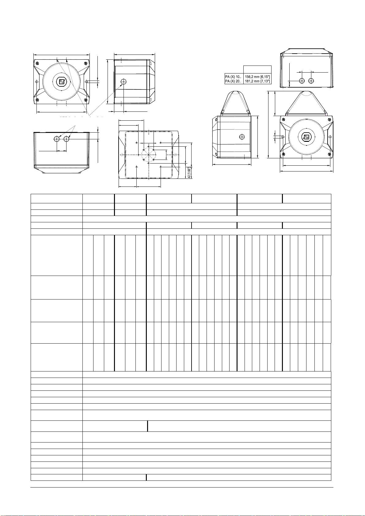
Размеры
PA X 10-10/ PA X 10-15
PA 10/ PA 20 PA X 20-10/ PA X 20-15
Технические данные
PA 10 PA 20 PA X 10-10 PA X 10-15 PA X 20-10 PA X 20-15
Ном
.
уровень
звука
110
дБ
(A) 1
м
085 501 946j 30305-004j 17
120
дБ
(A) 1
м
110 дБ (A) 1 м 120 дБ (A) 1 м
Регулировка
звука
-10 дБ -9 дБ -10 дБ -9 дБ
Тон
80
Энергия
вспышки
- 10 Дж 15 Дж 10 Дж 15 Дж
Частота
вспышки
- 1 Гц
Рабочее
напряжение
24 В DC или
12-48 В DC
24В AC 50/60Гц
1
10
–
240
В AC
50/60Гц
24 В DC
50/60Гц
12 В DC
24 В DC
12 В DC
24 В DC
48 В DC
12 В DC
24 В DC
48 В DC
12 В DC
24 В DC
48 В DC
или 12-48 В DC
24В AC 50/60Гц
110 – 240 В AC
48 В DC 50/60Гц
24В AC 50/60Гц
115В AC 50/60Гц
230В AC 50/60Гц
24В AC 50/60Гц
115В AC 50/60Гц
230В AC 50/60Гц
24В AC 50/60Гц
115В AC 50/60Гц
230В AC 50/60Гц
24В AC 50/60Гц
115В AC 50/60Гц
230В AC 50/60Гц
Диапазон
рабочего
напряжения
10..60B
20..30B
95 - 265B
10..60B
20..30B
95 - 265B
10,5..15B
18..30B
40..60B
20..30B
95..127B
195..253B
10,5..15B
18..30B
40..60B
20..30B
95..127B
195..253B
10,5..15 B
18..30B
40..60B
20..30B
95..127B
195..253B
10,5..15 B
18..30B
40..60B
20..30B
95..127B
195..253B
Номинальный
ток
,
потребляемый
излучателем
звука
(
Макс
) [
мА
]
24
В
: 360
485
850
140
2
4
В
: 800
880
1600
330
490
360
230
850
150
100
490
360
230
850
150
100
460
800
500
1600
330
200
460
800
500
1600
330
200
Номинальный
ток
,
потребляемый
проблесковой
лампой
(
Макс
) [
мА
]
–
–
–
–
–
–
1400
680
300
1400
300
160
1550
850
440
1400
330
220
1400
680
300
1400
300
160
1550
850
440
1400
330
220
Мощность
24
В
: 8,5
вт
12
-
48
В
:
9
вт
17,5 VA
15,5 VA
24
В
: 24,5
вт
12
-
48
В
:
27
вт
50 VA
22 вт
22 вт
32 вт
29 вт
57 VA
45 VA
38 вт
80 VA
72 VA
35 вт
51 вт
97 VA
17,5 VA
54,5 VA
34,5 VA
40,5 VA
27,5 вт
32,5 вт
65,5 VA
27,5 вт
50,5 вт
62,5 VA
43,5 вт
82,5 VA
72,5 VA
Рабочий
цикл
100%
Соединения
0,14 - 2,5
мм
²,
с
тонким
проводом
/ AWG24 - AWG 14 (
многожильное
)
Тип
защиты
IP66 (EN60529), Type 4 & 4x
Класс
защиты
II
Рабочая
температура
-40°C…+55°C
Температура
хранения
-40°C…+70°C
Макс
.
отн
.
влажность
90%
воздуха
M20, 7
шт
,
предварительно
Кабельный
ввод
M20, 5
шт
,
предварительно
подготовлены
подготовлены
Область
уплотнения
7 – 13
мм
;
при
использовании
кабеля
диаметром
менее
7
мм
должна
применяться
резьбовая
проводной
втулки
втулка
с
соответствующим
классом
защиты
Материал
корпуса
Поликарбонат
/
акрилонитрил
-
бутадиен
-
стирол
Материал
линзы
Поликарбонат
Монтажное
положение
Содержимое
упаковки
:
214 [8.44"]
L
1
устройство
сигнализации
1
мембранный
ниппель
М
20
1
руководство
по
эксплуатации
1
резистор
(
только
-SSM)
L
37 [1.46"]
Ø9 [0.35"]
26 [1.02"]
170 [6.69"]
190 [7.48"]
37 [1.46"]
100 [3.94"]
M20-Ausbruch vorbereitet/
89.4 [3.52"]
установка
через
скрытые
Отверстие
Prepared M20 cut-out
М
20 (
подготовлено
)
70.7 [2.78"]
внутренние
отверстия
270 [10.63"]
35.4
[1.39"]
170 [6.69"]
Ø9 [0.35"]
37 [1.46"]
35.4
[1.39"]
26 [1.02"]
60 [2.36"]
86 [3.39"]
L
190 [7.48"]
214 [8.44"]
55 [2.17"]
64.2 [2.53"]
86 [3.39"]
Произвольное
Опции
-SSM (
см
.
стр
. 21)
Аксессуары
Пломбировочные
пробки
(
арт
. 28300000002)
Цвет
линзы
-
прозрачная
,
белый
,
жёлтый
,
оранжевый
,
красный
,
зелёный
,
синий
Допуски
Допуски
(только для оборудования с маркировкой)
PA10/ PA 20, 110-230 AC: PA10/ PA 20, 24-48 DC: PA10-SSM, PA 20-SSM:
VdS 0786-CPD- 21184 VdS 0786-CPD- 21223 0786-CPD- 21224
Директива
Европейского
Союза по
строительным
изделиям
(89/106/EWG)
085 501 946j 30305-004j 18
PA 10/ PA 20
Опции –SSM
Рабочее напряжение
24 - 48 В DC
110 – 240
В
AC
Диапазон рабочего напряжения
18 – 60 В
95 – 265
В
AC
согласно EN54-3
Опция: -SSM (18 – 30 В)
Тональность
Согласно Директиве ЕС по строительным изделиям (89/106/EWG)
2
1200-500 Гц (звук пилы DIN/PFEER P.T.A.P.)
15
500-1200 Гц (с повышением тональности)
60
825 Гц (постоянная тональность)
104
660 Гц (с прерыванием)
131
800 / 1000 Гц (меняющаяся тональность)
146
544 / 440 Гц (NF S 32-001)
Область использования сигнализации EN54-3: см. документ 30305-005-1 (PA 10) и 30305-006-1 (PA 20)
Класс защиты окружающей среды Б
Испытания проводились с использованием мембранного ниппеля (в комплекте) и внешних крепежных
отверстий.
PA10 / PA 20, 110 – 230 AC: PA10/ PA 20, 24 - 48 DC: PA10-SSM, PA 20-SSM:
Союз
G212116 G212191 G212192
страховщиков
см. Директиву ЕС по строительным изделиям (89/106/EWG)
GLxxxxx (в процессе подготовки)
GL
Класс безопасности по отношению к окружающей среде C, H, EMC1
UL, cUL UCST, UCST7, ULSZ, ULSZ7, UEES, UEES7 (Дополнительную информацию см. на стр. 7)
Ввод в эксплуатацию
Указания по технике безопасности:
-
Подключение
электрооборудования
разрешается
выполнять
только
уполномоченным
сотрудникам
в
соответствии
с
предписаниями
действующего
законодательства
.
-
Осторожно
:
высокое
напряжение
во
время
работы
.
-
Во
время
монтажных
работ
питание
должно
быть
отключено
от
устройства
.
-
Перед
вводом
в
эксплуатацию
следует
проверить
соответствие
напряжения
данным
,
указанным
на
заводской
табличке
.
При
подключении
неверного
напряжения
оборудование
может
быть
повреждено
или
выведено
из
строя
.
-
Во
время
монтажа
необходимо
предусмотреть
меры
,
чтобы
проводка
не
могла
быть
вытянута
или
перекручена
.
Следует
принять
во
внимание
,
что
данные
устройства
не
являются
переносными
.
-
ВНИМАНИЕ
!
При
монтаже
проводка
не
должна
касаться
острых
краёв
,
углов
и
внутренних
компонентов
.
-
Отверстие
рупора
не
должно
быть
направлено
вверх
,
особенно
при
использовании
вне
помещения
или
в
запылённой
среде
.
-
Надлежащее
функционирование
устройства
гарантируется
только
в
том
случае
,
если
верхняя
и
нижняя
части
смонтированы
правильно
.
Комбинированные
светозвуковые
устройства
(PA X 10-10; PA X 10-15; PA X 20-10; PA X 20-15):
-
Чтобы
исключить
отрицательное
влияние
на
зрение
,
не
рекомендуется
долго
смотреть
на
включенную
проблесковую
лампу
.
Открывание корпуса: Закрывание корпуса
1. 2.
1. 2.
Корпус
закрывается
путём
Верхнюю
часть
можно
поворота
винтов
крышки
снять
после
поворота
до
фиксации
в
конечном
винтов
крышки
.
положении
.
3/8
3/8
Устройство
поставляется
в
открытом
состоянии
.
В
качестве
аксессуаров
предлагаются
пломбировочные
пробки
.
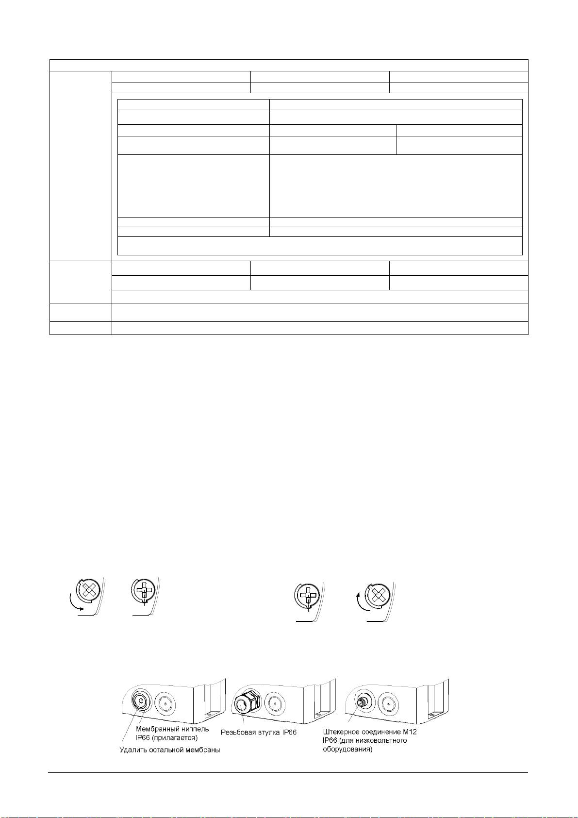
Кабельный ввод
Для
сохранения
имеющегося
класса
защиты
в
предусмотренные
отверстия
должны
быть
установлены
кабельные
вводы
класса
IP 66.
Поставляемый
мембранный
ниппель
можно
заменить
резьбовой
втулкой
или
штекерным
соединением
М
12
с
фланцем
М
20.
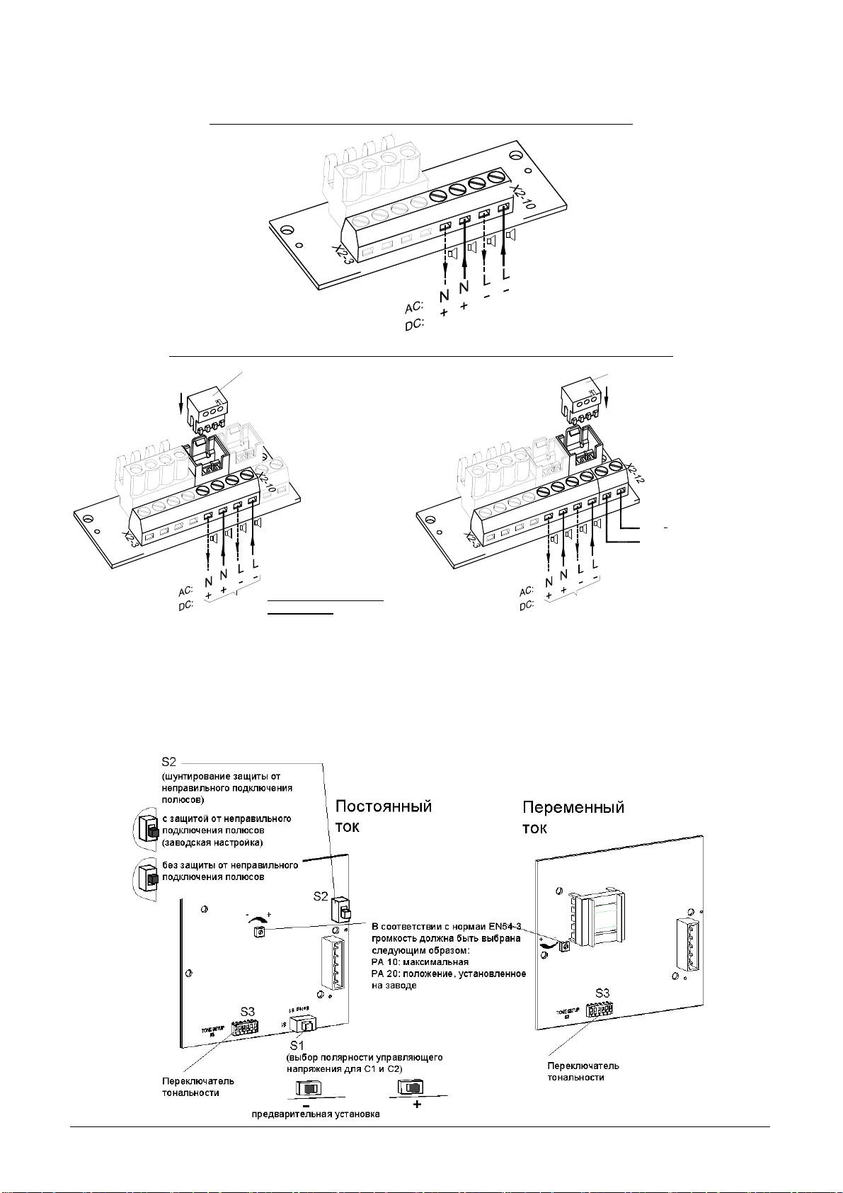
Клеммная колодка в нижней части:
Подключение питания и выбор тональности посредством внешней настройки (С1 и С2)
Подключение рабочего напряжения для звукового оповещения:
-L
-L
+N
+N
C1
C1
X2
C2
C2
Betriebsspannungs-
anschluss
Подключение рабочего напряжения для звукового и светового оповещения:
Stecker von der Blitzleuchtenplatine
X3
X4
-L
+N
-L
-L
+N
+N
C1
C1
C2
X2
C2
X2
Schallgeber und Blitzleuchte
Betriebsspannungs-
anschluss
085 501 946j 30305-004j 19
anschluss für Blitzleuchte:
X4
X3
-L
+N
-L
Betriebsspannungs-
-L
+N
+N
C1
L
C1
C2
N
+
C2
AC:
DC:
Stecker von der Blitzleuchtenplatine
Подключение рабочего
напряжения
Штекер платы
Штекер платы
проблесковой лампы
проблесковой лампы
Подключение
рабочего
напряжения
для
светового
оповещения
Подключение рабочего
напряжения для
светового и звукового
Подключение
Betriebsspannungs-
рабочего
оповещения
напряжения
anschluss für Schallgeber
для
звукового
оповещениясигнализации
Общее подключение звуковой и
световой сигнализации Раздельное подключение
(вид поставляемого изделия) звукового и светового оповещения
Тональность можно выбрать с помощью переключателя S3 (задающая сигнал плата в верхней части).
Описание возможных тональностей см. в таблице в приложении.
После подключения питания включается звук выбранной тональности.
Клеммная колодка (в верхней части устройства):
Изменение тональности посредством внешней настройки
Для случаев, когда требуется более одной звуковой тональности, посредством электрической настройки можно
выбрать до трёх дополнительных.
Прежде всего, устанавливается основная тональность (♪, см. таблицу в приложении) с помощью переключателя S3
на задающей сигнал плате. Дополнительную тональность (C1, C2, C1+C2) см. в таблице «Выбор тональности» в
приложении.
Выбор тональности через вход управления (TAS)
Версия, работающая от постоянного тока:
При правильном подключении полюсов выбор
Постоянный ток
тональности осуществляется через входы С1 и С2
защита
от
клеммной колодки. При этом должны быть подключены
неправильного
mit Verpolungsschutz
подключения
как входы управления, так и напряжение питания.
(with rectifier)
полюсов
Переключателем S2 на задающей пластине включена
S2
заводская
Werkseinstellung
защита от неправильного подключения полюсов (with
настройка
rectifier).
С помощью переключателя S1 на задающей сигнал
или
S1
S1
пластине осуществляется выбор управляющего
напряжения («+» или «–»).
+
положительный
positive
negative
«+»: положительная настройка
«–»: отрицательная настройка (заводская)
Внимание: Если управляющее напряжение
превосходит напряжение питания или напряжение
питания отсутствует, ток питания подаётся через входы
управления. При этом нагрузка не должна превышать
допустимую.
Версия, работающая от переменного тока:
В версии, работающей от переменного тока, выбор
тональности осуществляется посредством
подключения фазы «L» напряжения питания к входу
управления С1 или С2. При этом должны быть
подключены как входы управления, так и линия
питания.
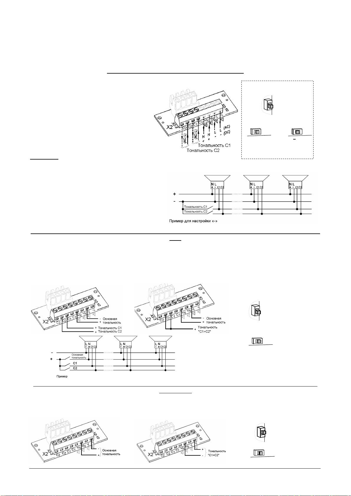
Выбор тональности путём подключения питания к входу управления TAV – для всех версий постоянного
тока
Рабочее напряжение можно подключить к звуковой сигнализации через входы управления С1 или С2 на клеммной
колодке. В этом случае входы служат как для выбора тональности, так и подачи питания.
Отрицательный полюс звуковой сигнализации должен быть подключен. Основная тональность устанавливается
путём подключения положительного контакта к положительному полюсу присоединительной планки (♪); при
подключении входов C1 и C2 настраивается соответствующая тональность.
При одновременном подключении положительного контакта к С1 и С2 выбирается тональность «С1+С2».
Переключатель S1 на задающей сигнал пластине должен находиться в положении «+».
mit Verpolungsschutz
(with rectifier)
S2
Werkseinstellung
S1
+
positive
Выбор тональности путём изменения полярности TAR – для всех версий постоянного тока тока (кроме
опции SSM)
Если переключателем S2 на задающей пластине не выбрана защита от неправильного подключения полюсов (без
выпрямителя = without rectifier), путём изменения полярности рабочего напряжения помимо основной тональности
(♪) можно выбрать тональность «C1+C2». Переключатель S1 должен быть в положении «+».
Входы управления С1 и С2 на присоединительной планке не должны быть подключены.
S2
ohne Verpolungsschutz
(without rectifier)
S1
+
positive
085 501 946j 30305-004j 20
отрицательный
(positive)
(negative)
положительный
без
защиты
от
неправильного
подключения
полюсов
(
без
выпрямителя
)
(with rectifier)
(positive)
без
защиты
от
неправильного
подключения
полюсов
(
без
выпрямителя
=
положительный
without
rectifier)
Опция SSM (Модуль плавного пуска) (только 24 В пост. тока):
- Максимальный пусковой ток
PA 10-SSM:
085 501 946j 30305-004j 21
:
макс
. 2,1 A
PA 20-SSM:
:
макс
. 4,5 A
PA X 10-xx-SSM:
:
макс
. 2,1 A
:
макс
. 4,5 A
PA X 20-xx-SSM:
:
макс
. 4,5 A
:
макс
. 4,5 A
- К устройству подводится напряжение питания, превышающее 7 В
- Резистор контроля кабеля
Диапазон рабочего напряжения: 18 – 30 В пост.тока
Резистор контроля цепи:
Резистор (1КОм) на подключении рабочего
Widerstand für Leitungsüberwachung (1KOhm)
напряжения.
am Betriebsspannungsanschluss.
-L
Положение Резистора в последнем
-L
Position des Widerstandes bei Parallelschaltung
+N
+N
устройстве при параллельном подключении
C1
C1
von mehreren Schallgebern im letzten Gerät.
X2
C2
нескольких звуковых оповещателей.
C2
nicht benötigte Widerstände entfernen
Техническое обслуживание и поддержание в исправном состоянии
Для данного устройства специальное техническое обслуживание не требуется. Очистка наружных
поверхностей осуществляется с помощью слабого мыльного раствора без использования растворителей.
Разрешается использовать устройство только в неповреждённом состоянии, согласно техническим
характеристикам. При изменении конструкции, модификации оборудования, его неправильном использовании
и использовании не по назначению, а также при несоблюдении указаний данного руководства гарантия
теряет свою силу.
Разрешается использовать только оригинальные запасные части. Ремонт производится только на
предприятии-изготовителе
.
Anhang/ Appendix/ Annexe
„Tonartentabelle“ und „Ansteuerung der Töne“
„Tone table“ and „Selection of the tones“
«Tableau des sons» et «Activation des sons»
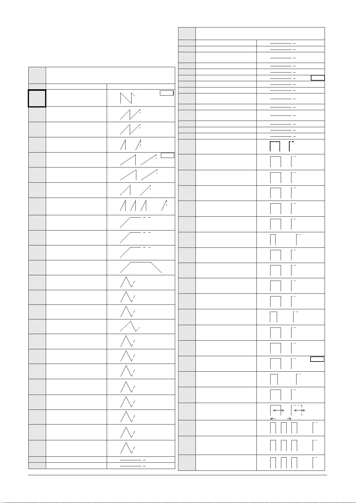
Tonartentabelle/ Tone table/ Tableau de sons
Grund-
085 501 946j 30305-004j 22
Ton-Nr.
Beschreibung/ Description
(♪)
1
Kein Ton/ Silence
Saw tooth, Germany DIN
1200Hz
1s
2
*
33404-3 (emergency signal),
PFEER PTAP
500Hz
970Hz
1s
Slow whoop, fire alarm, UK
9
BS5839-1
800Hz
970Hz
20ms
11
Whoop (fast)
800Hz
900Hz
0,3s
13
Whoop
700Hz
0,6s
1200Hz
3,5s
Slow whoop, evacuation,
15
Netherlands NEN 2575
500Hz
0,5s
1200Hz
3,75s
Slow whoop, evacuation
16
Australia AS2220
0,25s
500Hz
775Hz
0,85s
18
Slow whoop, NFPA
422Hz
1s
1200Hz
0,5s
Whoop, Australia AS1670,
22
ISO8201
500Hz
1,5s
0,5s
2400Hz
3s
const.
23
Siren
500Hz
1200Hz
3s
const.
24
Siren
300Hz
800Hz
3s
const.
25
Siren
300Hz
1000Hz
10s
40s
10s
26
Industrial alarm (Germany)
150Hz
2900Hz
0,5s
27
Sweeping
2400Hz 0,5s
2900Hz
10ms
29
Sweeping (fast)
2400Hz 10ms
2900Hz
70ms
30
Sweeping
2400Hz 70ms
1600Hz
1s
Sweeping,
31
France NF C 48-265
1400Hz
0,5s
1000Hz
0,5s
Sweeping, UK BS5839-1
33
(medium sweep)
800Hz 0,5s
1000Hz
10ms
34
Sweeping (fast)
800Hz 10ms
1000Hz
70ms
Sweeping,
35
UK BS5839-1 (fast sweep)
800Hz 70ms
1500Hz
1,5s
36
Sweeping
700Hz 1,5s
1200Hz
1,5s
43
Sweeping
500Hz 1,5s
1200Hz
1s
Sweeping, IMO 3d, Germany
44
KTA3901 evacuation
500Hz 1s
1200Hz
3s
45
Sweeping
500Hz 3s
1500Hz
7s
Sweeping,
46
Finland General Alarm
500Hz 7s
52
Continuous
2400Hz
53
Continuous
2000Hz
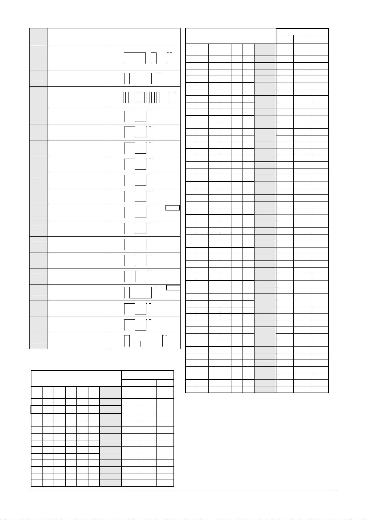
(♪)
Beschreibung/ Description
54
Continuous, Finland All Clear
1500Hz
55
Continuous
1200Hz
Continuous, PFEER (Gasa-
56
1000Hz
larm)
57
Continuous, UK BS5839-1
950Hz
59
Continuous
880Hz
60
Continuous
825Hz
61
Continuous
800Hz
63
Continuous
725Hz
Continuous, Sweden
65
660Hz
SS031711 (All Clear)
66
Continuous
554Hz
Continuous, Germany
67
500Hz
KTA3901 (All Clear)
68
Continuous
470Hz
69
Continuous
440Hz
71
Continuous
340Hz
2400Hz
77
Intermittent
0,5s 0,5s
Intermittent, PFEER (General
1000Hz
82
Alarm), UK BS5839-1 (Back-
up Alarm)
0,5s 0,5s
1000Hz
Intermittent, PFEER (General
83
Alarm)
1s 1s
950Hz
88
Intermittent
1s 1s
825Hz
90
Intermittent
0,5s 0,5s
800Hz
91
Intermittent
0,25s 0,25s
800Hz
92
Intermittent
0,25s
1s
800Hz
Intermittent (fast), electrome-
93
chanical horn
4ms 4ms
725Hz
97
Intermittent
0,7s
0,3s
700Hz
Intermittent, Sweden SS
98
031711 (Imminent Danger)
0,125s 0,125s
680Hz
Intermittent, Industrial Alarm
100
(Germany)
0,875s 0,875s
Intermittent, Sweden
660Hz
101
SS031711 (Important Mes-
sage (Pre Mess))
6,5s
13s
660Hz
Intermittent, Sweden
102
SS031711 (Local Warning)
0,5s 0,5s
660Hz
Intermittent, Sweden
103
SS031711 (Air Raid)
1,8s 1,8s
Intermittent, Sweden
660Hz
104
SS031711 (Imminent Dan-
ger)
150ms 150ms
500Hz
Intermittent, Germany
107
KTA3901 (evacuation)
0,25s
0,75s
420Hz
Intermittent, Australia
109
AS2220,AS1610, AS1670
0,625s 0,625s
1450Hz
Intermittent (fast variable),
110
Bell
0,69ms
Intermittent, ISO8201 (emer-
470Hz
111
gency evacuation signal),
0,5s
USA (evacuation)
0,5s
1,5s
950Hz
Intermittent, ISO8201 (emer-
112
0,5s
gency evacuation signal)
0,5s
1,5s
Intermittent, ISO8201 (emer-
2850Hz
113
gency evacuation signal)
0,5s
treble tone
0,5s
1,5s
EN54
-
3
EN54
-
3
EN54
-
3
EN54
-
3
Grund-
085 501 946j 30305-004j 23
Ton-Nr.
Beschreibung/ Description
(♪)
950Hz
Intermittent,
2s
115
0,5s
IMO (Telephone Call)
0,5s
1s
950Hz
Intermittent, IMO
3s1s
116
(abandon ship)
1s 1s
Intermittent,
825Hz
IMO SOLAS III/50 +
117
SOLAS III/6.4 (General
Alarm)
2,5s
7s
2,5s
2900Hz
0,5s
122
Alternating
2400Hz
0,5s
2900Hz
0,25s
123
Alternating
2400Hz
0,25s
2000Hz
0,5s
124
Alternating, Singapore
1000Hz
0,5s
1400Hz
20ms
125
Alternating
1200Hz
20ms
1025Hz
0,25s
128
Alternating
825Hz
0,25s
1000Hz
Alternating, UK BS5839-1
0,5s
130
(Fire Alarm)
800Hz
0,5s
1000Hz
Alternating, UK BS5839-1
0,25s
131
(Fire Alarm, Level crossing)
800Hz
0,25s
Alternating, UK BS5839-1
1000Hz
0,125s
135
(Fire Alarm, increased urgen-
800Hz
0,125s
cy Level crossing)
900Hz
0,25s
142
Alternating
500Hz
0,25s
660Hz
Alternating,
0,125s
143
Germany Industrial Alarm
440Hz
0,125s
1s
144
Alternating
440Hz
1s
Alternating,
554Hz
146
France NFS 32-001 (fire
0,1s
440Hz
0,4s
alarm)
Alternating,
147
Sweden SS031711 (turn out)
554Hz
1s
440Hz
1s
554Hz
Alternating, Sweden
0,5s
148
SS031711 (turn out)
440Hz
0,5s
800Hz
152
Alternating-intermittent
650Hz
0,25s
0,25s
2s
Ansteuerung der Töne/ Selection of the tones/
Activation des sons:
Tonartenschalter/ Selector –switch
External Tone Control
(Einstellung des Grundtones/
Adjusting the base tone)
C1 C2 C1+C2
Grund-Ton
Tone
Tone
Tone
1 2 3 4 5 6
No.
(♪)
No.
No.
No.
1 2 88 57
ON
2
*
128 112 57
ON
2 26 100 93
ON
ON
2 61 131 112
ON
9 57 11 82
ON
ON
15 131 52 112
ON
ON
16 109 52 56
ON
ON
ON
18 111 57 68
ON
22 16 109 68
ON
ON
23 131 52 112
ON
ON
24 131 52 131
ON
ON
ON
25 131 52 92
ON
ON
Tonartenschalter/ Selector –switch
External Tone Control
(Einstellung des Grundtones/
Adjusting the base tone)
C1 C2 C1+C2
26 2 100 93
Grund-Ton
Tone
Tone
Tone
1 2 3 4 5 6
No.
(♪)
No.
No.
No.
ON
ON
ON
27 123 52 92
ON
ON
ON
29 35 52 61
ON
ON
ON
ON
30 27 52 77
ON
31 131 52 57
ON
ON
33 30 52 35
ON
ON
34 35 52 93
ON
ON
ON
35 27 52 110
ON
ON
36 146 67 57
ON
ON
ON
43 131 52 91
ON
ON
ON
45 2 57 93
ON
ON
ON
ON
52 15 65 82
ON
ON
54 46 54 131
ON
ON
ON
55 131 52 128
ON
ON
ON
56 82 35 33
ON
ON
ON
ON
59 143 59 101
ON
ON
ON
60 131 52 125
ON
ON
ON
ON
65 131 52 93
ON
ON
ON
ON
66 110 52 107
ON
ON
ON
ON
ON
69 131 52 110
ON
71 131 52 93
ON
ON
77 61 52 122
ON
ON
82 131 52 83
ON
ON
ON
83 56 2 82
ON
ON
88 2 57 128
ON
ON
ON
90 131 52 125
ON
ON
ON
91 30 52 110
ON
ON
ON
ON
92 33 52 57
ON
ON
93 2 128 57
ON
ON
ON
97 2 63 93
ON
ON
ON
100 131 52 125
ON
ON
ON
ON
101 98 102 65
ON
ON
ON
103 131 65 147
ON
ON
ON
ON
104 103 65 101
ON
ON
ON
ON
109 16 52 22
ON
ON
ON
ON
ON
110 131 61 91
ON
ON
112 2 57 128
ON
ON
ON
113 52 123 104
ON
ON
ON
115 117 116 44
ON
ON
ON
ON
116 117 93 125
ON
ON
ON
117 93 116 125
ON
ON
ON
ON
123 27 52 77
ON
ON
ON
ON
124 53 83 2
ON
ON
ON
ON
ON
130 2 107 67
ON
ON
ON
131 2 112 57
ON
ON
ON
ON
135 16 56 109
ON
ON
ON
ON
142 2 54 88
ON
ON
ON
ON
ON
143 59 93 33
ON
ON
ON
ON
144 110 61 2
ON
ON
ON
ON
ON
146 31 67 57
ON
ON
ON
ON
ON
148 131 52 92
ON
ON
ON
ON
ON
ON
650Hz
152 110 61 13
*
Werkseinstellung/ Factory setting/ Réglage d’usine
Заводская настройка
EN54
-
3
EN54
-
3

12/2013
Pfannenberg GmbH
Werner-Witt-Straße 1
·
D- 21035 Hamburg
Tel.: +49/ (0)40/ 734 12-0
·
Fax: +49/ (0)40/ 734 12-101
technical.support @pfannenberg.com
http://www.pfannenberg.com
085501946
