Partner T265 CPS Rev.7: ASSEMBLY
ASSEMBLY: Partner T265 CPS Rev.7
• INSPECT YOUR TRIMMER AND ATTA-
• DO NOT RAISE TRIMMER HEAD above
CHMENTS BEFORE EACH USE - Never
ground level while unit is operating. Injury
use unless all bladeattaching hardware is
to operator could result.
properly installed.
• DO NOT USE UNIT FOR ANY
• BLADE COASTS AFTER THROTTLE IS
PURPOSES OTHER than trimming lawn
RELEASED - A coasting blade can cut
or garden areas.
you or bystanders. Before performing any
• DO NOT OPERATE UNIT FOR PROL-
service on the blade, always turn off
ONGED PERIODS. Rest periodically.
engine, and be sure coasting blade has
• DO NOT OPERATE UNIT WHILE
stopped.
UNDER THE INFLUENCE OF ALCOHOL
• 50-FOOT (15 meters) DIAMETER HAZA-
OR DRUGS.
RD ZONE - Bystanders can be blinded or
• DO NOT OPERATE UNIT UNLESS
injured. Keep people and animals 50 feet
CUTTING ATTACHMENT GUARD AND/
(15 meters) away in all directions.
OR GUARD IS INSTALLED AND IN
GOOD CONDITION.
WHAT NOT TO DO
• DO NOT ADD, REMOVE OR ALTER ANY
• DO NOT USE ANY OTHER FUEL than
COMPONENTS OF THIS PRODUCT.
that recommended in your manual.
Doing so could cause personal injury
Always follow instructions in the Fuel and
and/or damage the unit voiding the
Lubrication section of this manual. Never
manufacturer’s warranty.
use gasoline unless it is properly mixed
• DO NOT operate your unit near or around
with 2-cycle engine lubricant. Permanent
flammable liquids or gases whether in or
damage to engine will result, voiding
out of doors. An explosion and/or fire may
manufacturer’s warranty.
result.
• DO NOT SMOKE while refueling or
• DO NOT USE ANY OTHER CUTTING
operating equipment.
ATTACHMENT. Use only replacement
• DO NOT OPERATE UNIT WITHOUT A
parts and accessories, which are design-
MUFFLER and properly installed muffler
ed specifically to enhance the performan-
shield.
ce and maximize the safe operation of our
• DO NOT TOUCH or let your hands or
products. Failure to do so may cause poor
body come in contact with a hot muffler or
performance and possible injury. Use only
spark plug wire.
the cutting head supplied with this
• DO NOT OPERATE UNIT IN AWKWARD
product. Do not use any other cutting
POSITIONS, off balance, outstretched
attachment. Use of such attachments will
arms, or one-handed. Always use two
void your factory warranty and could
hands when operating unit with thumbs
result in serious bodily injury.
and fingers encircling the handles.
ASSEMBLY
WARNING: Please assemble the
unit according to the assembly instructions.
Failure to do so may cause injury to the
operator.
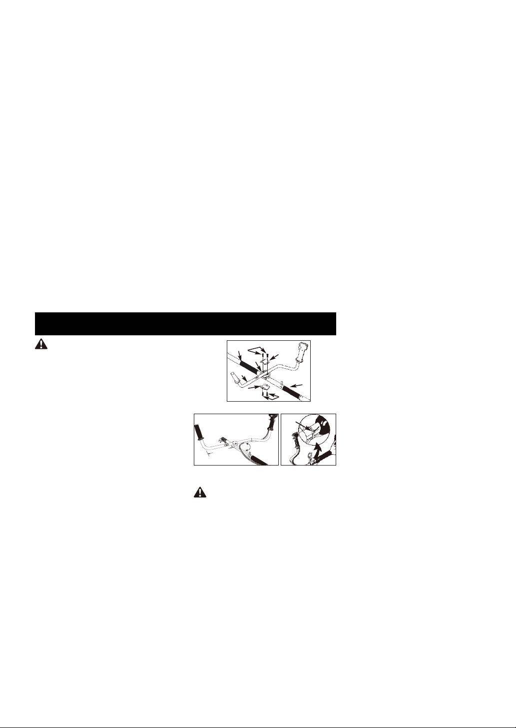
“Bullhorn¨ HANDLE INSTALLATION
1. To install handle onto unit, you will need
the following components from your user
kit: “Bullhorn” handle (A), fixing holder (B),
clamp (C) and screws (D). (Fig.1A)
2. IInstall the fixing holder (B) between the
sponge sleeve (E and G), and adjust it to a
proper position.
3. Install the Bullhorn handle (A) on the fixing
holder, put the other clamp (C) over
bullhorn-handle, adjust handle to
appropriate position and tighten the other 2
INSTALLING THE ATTACHMENT
screws (D). The left handle shall be at least
200mm horizontally perpendicularly from
WARNING: To avoid serious
the shaft tube. The handle shaft must be
personal injury, shut unit off before
mounted on the right side of direction of
removing or installing attachment.
arrow head on the handle shaft. (Fig.1B)
NOTE: To make installing or removing the
4. Install wire tie (F) included in the user kit as
attachment easier, place the unit on the
shown (Fig.1C).
ground or on a work bench.
1. Turn the knob (A) counterclockwise to
loosen (Fig. 2A).
-- 4 --
90ß
G
D
C
B
A
E
C
D
Fig.1A
F
200mm
(minimum)
Fig.1B Fig.1C
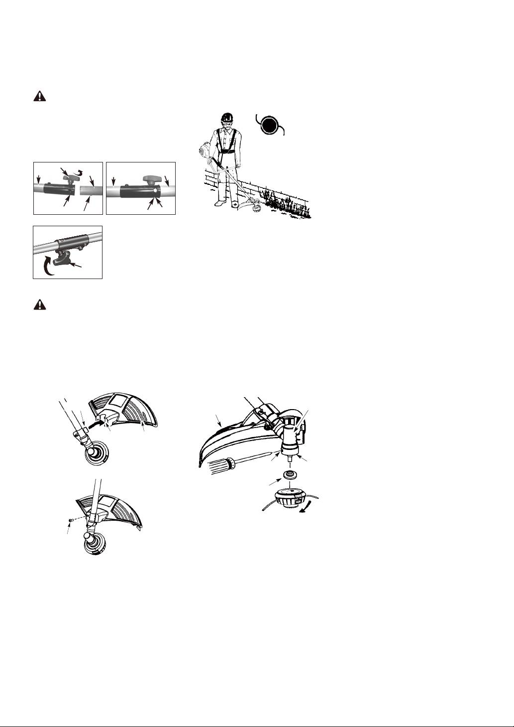
2. While firmly holding the attachment (B),
CONFIGURING YOUR UNIT
push it straight into the Quick-Change
You can configure your unit using a cutting
coupler (C) until the release button (D)
head for grass and light weeds, or a weed
appears in the primary hole (E) of the
blade for cutting grass, weeds, and brush up
Quick-Change coupler. (Fig. 2B)
to 1 cm in diameter. To assemble your unit,
3. Turn the knob (A) clockwise to tighten.
go to the section for the desired
(Fig. 2C)
configuration and follow the instructions.
CAUTION: The release button must
ASSEMBLY INFORMATION -
be in the primary hole and the knob securely
TRIMMER HEAD
tightened before operating this unit.
All attachments are designed to be used in
the primary hole unless otherwise indicated
in the specific attachments operators
TRIMMER
manual. If the incorrect hole is used, it could
HEAD
result in injury, or damage to the unit.
A
C
B
C
B
E
D
D
E
Fig. 2A Fig. 2B
NOTE: Remove the blade before attaching
the trimmer head. To remove blade, align
hole in the dust cup with the hole in the side
of the gearbox by rotating the blade. Insert a
small screwdriver into aligned holes. This
will keep the shaft from turning while
loosening the blade nut. Remove blade nut
by turning clockwise. Remove the
Fig. 2C
screwdriver. Remove both washers and
ATTACHING THE SHIELD
blade. See INSTALLATION OF THE
METAL BLADE for illustrations. Be sure to
WARNING: The shield must be
store all parts and instructions for future
properly installed. The shield provides
use. Never use the trimmer head with the
partial protection to the operator and thers
metal blade installed.
from the risk of thrown objects, and is
INSTALLATION OF THE TRIMMER
equipped with a line limiter blade which cuts
excess line to the proper length.
HEAD
The line limiter blade (on underside of
NOTE: If your unit has a plastic cover over
shield) is sharp and can cut you.
the threads on the threaded shaft, remove
1. Insert bracket into slot on shield.
the covering to expose the threads. Before
2. Pivot shield to align holes in shield and
installing the trimmer head, make sure the
bracket.
dust cup and retaining washer are
positioned on the gearbox.
Bracket
Gearbox
Shield
Slot
Shield
Aligned holes
Dust cup
3. Secure shield to bracket with bolt.
Retaining washer
NOTE: Make sure all parts are properly
installed as shown in the illustration before
installing the trimmer head.
Bolt
1. Align hole in the dust cup with the hole in
the side of the gearbox by rotating the
dust cup.
-- 5 --
2. Insert a small screwdriver into aligned
5. Install the blade nut by threading onto the
holes. This will keep the shaft from
shaft counterclockwise.
turning while tightening trimmer head.
3. While holding the screwdriver in position,
Shield
Gearbox
thread trimmer head onto the shaft in the
direction shown on the decal
(counterclockwise). Tighten until secure.
NOTE: The retaining washer must be
Dust cup
positioned with the raised section facing
toward the gearbox.
Threaded
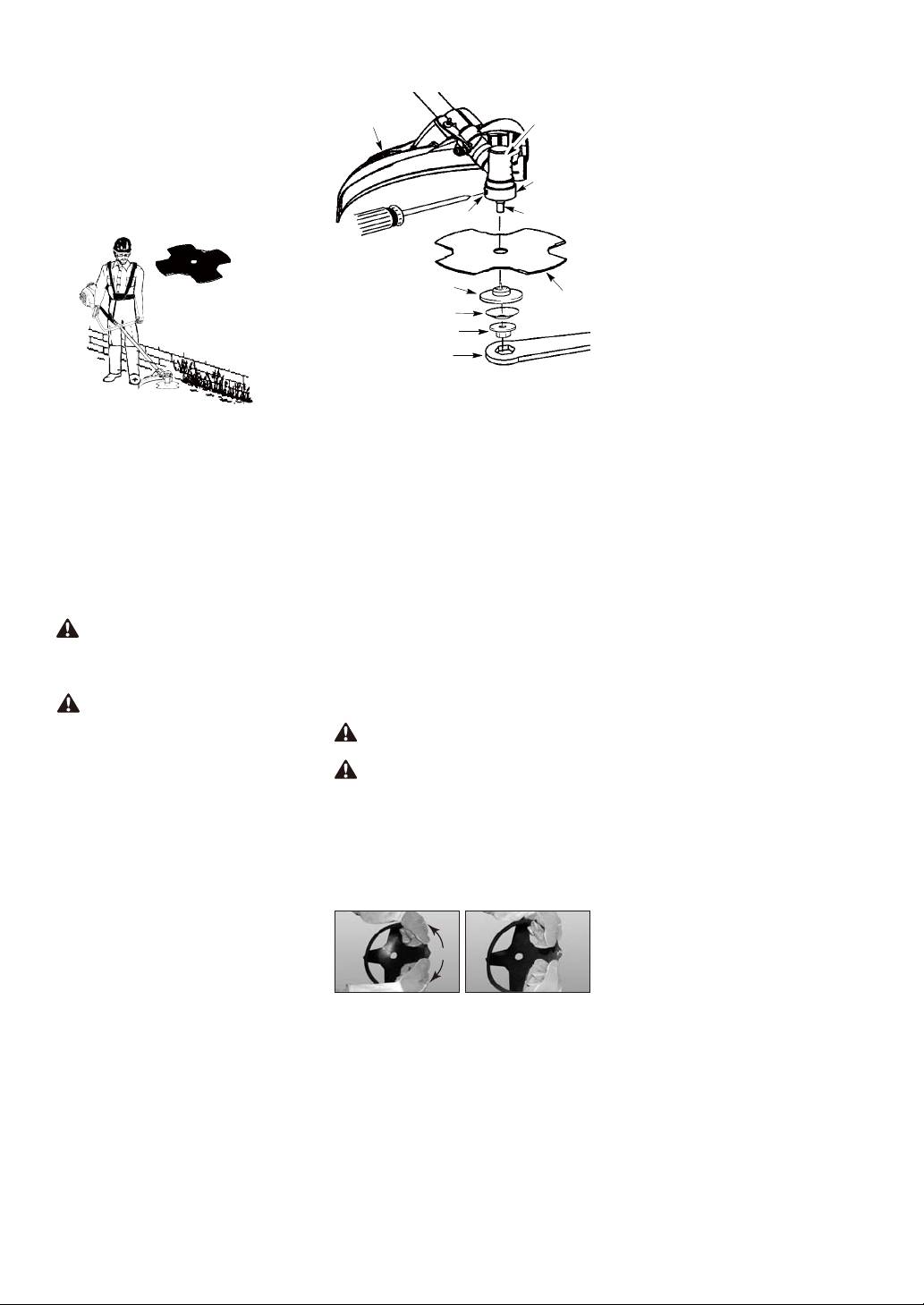
ASSEMBLY INFORMATION -
Aligned holes
shaft
WEED BLADE
WEED
BLADE
Retaining washer
Blade
Cupped washer
Nut
Wrench
NOTE: Make sure all parts are in place as
illustrated, and the blade is sandwiched
between the dust cup and the retaining
NOTE: Remove the trimmer head before
washer. There should be no space between
installing the weed blade. To remove the
the blade and the dust cup or the retaining
trimmer head, align hole in the dust cup with
washer.
the hole in the side of the gearbox by
6. Align hole in dust cup with hole in side of
rotating the dust cup. Insert a small
gearbox by rotating the blade.
screwdriver into aligned holes. This will
7. Insert a small screwdriver into aligned
keep the shaft from turning while loosening
holes. This will keep the shaft from
the trimmer head. Remove the trimmer
turning while tightening the blade nut.
head by turning clockwise. Remove the
8. Tighten blade nut firmly with wrench
screwdriver.
(provided) while holding screwdriver in
See INSTALLATION OF THE CUTTING
position.
HEAD for illustrations. Be sure to store all
9. Remove the screwdriver.
parts and instructions for future use.
10.Turn blade by hand. If the blade binds
INSTALLATION OF THE METAL
against the shield, or appears to be
BLADE
uneven, the blade is not centered, and
you must reinstall.
WARNING: Wear protective gloves
NOTE: To remove blade, insert screwdriver
when handling or performing maintenance
into aligned holes. Unthread the nut and
on the blade to avoid injury. The blade is
remove parts. Be sure to store parts and
sharp and can cut you even when it is not
instructions for future use.
moving.
REMOVE AND INSTALLATION THE
WARNING: Do not use any blades,
BLADE COVER
or fastening hardware other than the
washers and nuts shown in the following
CAUTION: Before you take apart the
illustrations. These parts must be provided
blades, wear gloves to prevent any danger.
and installed as shown below. Failure to use
proper parts can cause the blade to fly off
CAUTION: When the machine is not
and seriously hurt you or others.
in use or in transportation, make sure
NOTE: The dust cup is located on the
blades have been covered.
gearbox shaft and not in the parts bag. All
1. Before assembling blades, please
other fasteners mentioned in the following
remove the blades cover first.
assembly steps are in the parts bag.
2. Refer figure 6A and Figure 6B, hold the
1. Install the blade and the retaining washer
blades cover, and pull sligtly the cover
over the threaded shaft.
outward the cover can be taken apart.
2. Make sure the raised part of the retaining
3. Refer to figure 6C and 6D, and assemble
washer is facing the gearbox and the
in the opposite way to cover the blades.
raised area fits into the hole in the center
of the blade.
3. Slide the blade and retaining washer
onto the shaft of the gearbox.
4. Place the cupped washer onto the shaft.
Make sure the cupped side of the washer
is toward the blade.
Fig. 6A Fig. 6B
-- 6 --
Оглавление
- IDENTIFICATION (WHAT IS WHAT?)
- SAFETY RULES
- ASSEMBLY
- FUEL AND LUBRICATION
- TRIMMER INSTRUCTIONS
- OPERATING INSTRUCTIONS FOR USE WITH BLADE
- MAINTENANCE INSTRUCTIONS
- DECLARATION OF CONFORMITY
- TECHNICAL DATA SHEET
- ОПИСАНИЕ ДЕТАЛЕЙ ИНСТРУМЕНТА
- ПРАВИЛА ТЕХНИКИ БЕЗОПАСНОСТИ
- СБОРКА
- ТЕХНИЧЕСКИЕ ХАРАКТЕРИСТИКИ
- IDENTIFIERING (VAD ÄR VAD?)
- SÄKERHETSREGLER
- MONTERING
- DRIFTSINSTRUKTIONER
- TEKNISKT DATABLAD
- IDENTIFIKASJON (HVA ER HVA?)
- SIKKERHETSREGLER
- ASSEMBLY
- INSTRUKSJONER FOR BRUK
- TEKNISKE DATA
- IDENTIFICERING (HVAD ER HVAD?)
- SIKKERHEDSREGLER
- SAMLING
- DRIFTSANVISNINGER
- TEKNISK DATAARK
- TUNNISTUS (MIKÄ ON OLEELLISTA?)
- TURVAOHJEET
- KOKOAMINEN
- KÄYTTÖOHJEET
- TEKNISET TIEDOT
- IDENTYFIKACJA (CO TO JEST?)
- ZASADY BEZPIECZEŃSTWA
- СБОРКА
- ARKUSZ DANYCH TECHNICZNYCH
- IDENTIFIKACE (CO JE CO?)
- BEZPEČNOSTNÍ PRAVIDLA
- MONTÁŽ
- TECHNICKÉ ÚDAJE
- ІДЕНТИФІКАЦІЯ (ЩО ЦЕ ТАКЕ?)
- ПРАВИЛА ТЕХНІКИ БЕЗПЕКИ
- ЗБИРАННЯ
- ТЕХНІЧНИЙ ПАСПОРТ
