MSI P67A-GD55 (B3) – страница 2
Инструкция к Материнской Плате Intel MSI P67A-GD55 (B3)
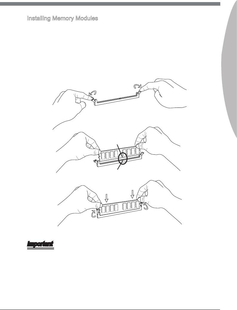
Installng Memory Modules
1.
The memory module has only one notch on the center and wll only t n the rght
orentaton.
2.
Insert the memory module vertcally nto the DIMM slot. Then push t n untl the
golden nger on the memory module s deeply nserted n the DIMM slot. The plastc
clp at each sde of the DIMM slot wll automatcally close when the memory module
Englsh
s properly seated.
3.
Manually check f the memory module has been locked n place by the DIMM slot
clps at the sdes.
Notch
Volt
Important
You can barely see the golden nger f the memory module s properly nserted n the
DIMM slot.
En-11
MS-7681 Manboard
Power Supply
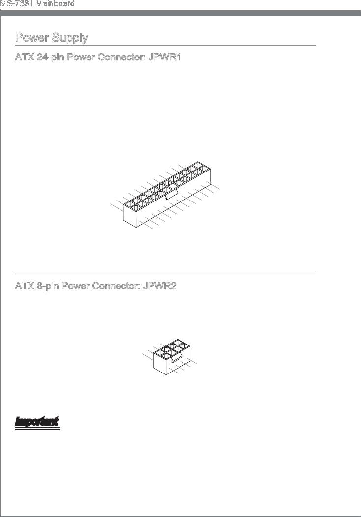
ATX 24-pn Power Connector: JPWR1
Ths connector allows you to connect an ATX 24-pn power supply. To connect the ATX
24-pn power supply, make sure the plug of the power supply s nserted n the proper
orentaton and the pns are algned. Then push down the power supply rmly nto the
connector.
You may use the 20-pn ATX power supply as you lke. If you’d lke to use the 20-pn
ATX power supply, please plug your power supply along wth pn 1 & pn 13.
En-12
12.+3.3
11
10.+12V
.+12V
9.5VSB
8.PW
V
7
6.+5
.Ground
5
R O
4.+5
.Ground
V
K
3
2.+3.3
.Ground
V
1.+3.3
24.Ground
V
23.+5
V
22.+5
21.+5
20.Res
V
19.Ground
V
18.Ground
V
17.Ground
16.PS-ON
15.Ground
14.-12V
13.+3.3
#
V
ATX 8-pn Power Connector: JPWR2
Ths connector s used to provde the power output to the CPU.
4
3.
.Ground
2
Ground
1.
.Ground
Ground
8.+12V
7.+12V
6.+12V
5.+12V
Important
Make sure that all the connectors are connected to proper ATX power supples to en-
sure stable operaton of the manboard.
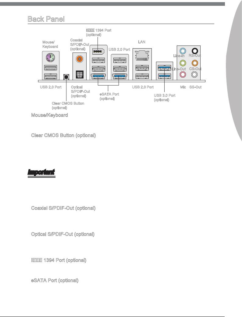
Back Panel
IEEE 1394 Port
(optonal)
Coaxal
Mouse/
LAN
S/PDIF-Out
Keyboard
(optonal)
USB 2.0 Port
Lne-In
RS-Out
Englsh
Lne-Out
CS-Out
Optcal
USB 2.0 Port
Mc
SS-OutUSB 2.0 Port
S/PDIF-Out
eSATA Port
(optonal)
USB 3.0 Port
(optonal)
(optonal)
Clear CMOS Button
(optonal)
▶
Mouse/Keyboard
®
®
The standard PS/2
mouse/keyboard DIN connector s for a PS/2
mouse/keyboard.
▶
Clear CMOS Button (optonal)
There s a CMOS RAM on board that has a power supply from external battery to keep
the system conguraton data. Wth the CMOS RAM, the system can automatcally
boot OS every tme t s turned on. If you want to clear the system conguraton, use
the button to clear data. Press the button to clear the data.
Important
•
Make sure that you power o the system before clearng CMOS data.
•
After pressng ths button to clear CMOS data n power o (G3) state, the system wll
boot automatcally.
▶
Coaxal S/PDIF-Out (optonal)
Ths SPDIF (Sony & Phlps Dgtal Interconnect Format) connector s provded for dgtal
audo transmsson to external speakers through a coaxal cable.
▶
Optcal S/PDIF-Out (optonal)
Ths SPDIF (Sony & Phlps Dgtal Interconnect Format) connector s provded for dgtal
audo transmsson to external speakers through an optcal ber cable.
▶
IEEE 1394 Port (optonal)
The IEEE 1394 port on the back panel provdes connecton to IEEE 1394 devces.
▶
eSATA Port (optonal)
The eSATA (External SATA) port s for attachng the eSATA hard drve.
En-13
MS-7681 Manboard
▶
USB 2.0 Port
The USB (Unversal Seral Bus) port s for attachng USB devces such as keyboard,
mouse, or other USB-compatble devces. Supports data transfer rate up to 480Mbt/s
(H-Speed).
▶
USB 3.0 Port (optonal)
USB 3.0 port s backward-compatble wth USB 2.0 devces. It supports data transfer
rate up to 5 Gbt/s (SuperSpeed).
Important
If you want to use a USB 3.0 devce, you must use the USB 3.0 cable to connect to the
USB 3.0 port.
▶
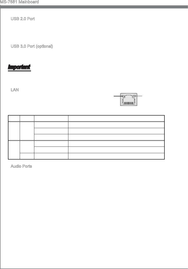
LAN
The standard RJ-45 LAN jack s for connecton to
Yellow Green/ Orange
the Local Area Network (LAN). You can connect a
network cable to t.
LED Color LED State Condton
Left Yellow O LAN lnk s not establshed.
On(Steady state) LAN lnk s establshed.
On(brghter & pulsng) The computer s communcatng wth another computer on the LAN.
Rght
Green O 10 Mbt/sec data rate s selected.
On 100 Mbt/sec data rate s selected.
Orange On 1000 Mbt/sec data rate s selected.
▶
Audo Ports
These audo connectors are used for audo devces. It s easy to derentate between
audo eects accordng to the color of audo jacks.
■
Lne-In: Blue - Lne In, s used for external CD player, tape-player or other audo
devces.
■
Lne-Out: Green - Lne Out, s a connector for speakers or headphones.
■
Mc: Pnk - Mc, s a connector for mcrophones.
■
RS-Out: Black (optonal) - Rear-Surround Out n 4/ 5.1/ 7.1 channel mode.
■
CS-Out: Orange (optonal)- Center/ Subwoofer Out n 5.1/ 7.1 channel mode.
■
SS-Out: Gray (optonal)- Sde-Surround Out 7.1 channel mode.
En-14
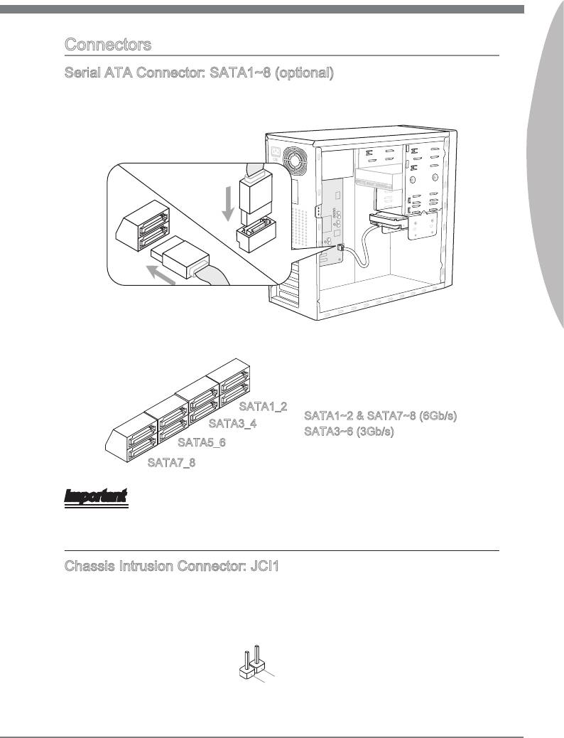
Connectors
Seral ATA Connector: SATA1~8 (optonal)
Ths connector s a hgh-speed Seral ATA nterface port. Each connector can connect
to one Seral ATA devce.
Englsh
* The MB layout n ths gure s for reference only.
SATA1_2
SATA1~2 & SATA7~8 (6Gb/s)
SATA3_4
SATA3~6 (3Gb/s)
SATA5_6
SATA7_8
Important
Please do not fold the Seral ATA cable nto a 90-degree angle. Otherwse, data loss
may occur durng transmsson.
Chasss Intruson Connector: JCI1
Ths connector connects to the chasss ntruson swtch cable. If the chasss s opened,
the chasss ntruson mechansm wll be actvated. The system wll record ths status
and show a warnng message on the screen. To clear the warnng, you must enter the
BIOS utlty and clear the record.
En-15
2
.
1
G
.
C
r
o
I
N
u
n
T
d
R
U
MS-7681 Manboard
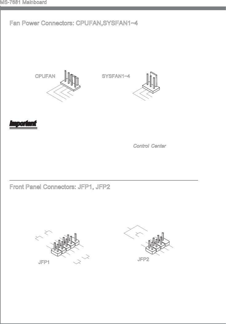
Fan Power Connectors: CPUFAN,SYSFAN1~4
The fan power connectors support system coolng fan wth +12V. When connectng the
wre to the connectors, always note that the red wre s the postve and should be con-
nected to the +12V; the black wre s Ground and should be connected to GND. If the
manboard has a System Hardware Montor chpset on-board, you must use a specally
desgned fan wth speed sensor to take advantage of the CPU fan control.
En-16
1
2
.
G
3
.
+
r
4
.
S
1
o
2
u
.
C
e
V
n
n
d
o
s
n
o
t
r
r
o
l
1
2
.
G
3
.
+
r
.
S
1
o
2
u
e
V
n
n
d
s
o
r
CPUFAN SYSFAN1~4
Important
Please refer to the recommended CPU fans at processor’s ocal webste or consult
the vendors for proper CPU coolng fan.
CPUFAN support Smart fan control. You can nstall
Control Center utlty that wll
automatcally control the CPUFAN speeds accordng to the actual CPUFAN tem-
peratures.
Fan cooler set wth 3 or 4 pns power connector are both avalable for CPUFAN.
Front Panel Connectors: JFP1, JFP2
These connectors are for electrcal connecton to the front panel swtches and LEDs.
®
The JFP1 s complant wth Intel
Front Panel I/O Connectvty Desgn Gude.
peaker
S
8.
Buzzer
6.
+
4.
-
2.
+
-
7.No Pi
5.Power
3.Suspend
1
.Ground
n
LE
D
LE
D
P
ower
P
S
ower
witch
10.No
LE
Pi
D
8.
n
6.
-
4.
+
2.
-
+
9.Reserve
7.
5.
+
3.
-
1.+
-
Reset
d
HDD
S
witch
LE
D
•
•
•
JFP2
JFP1
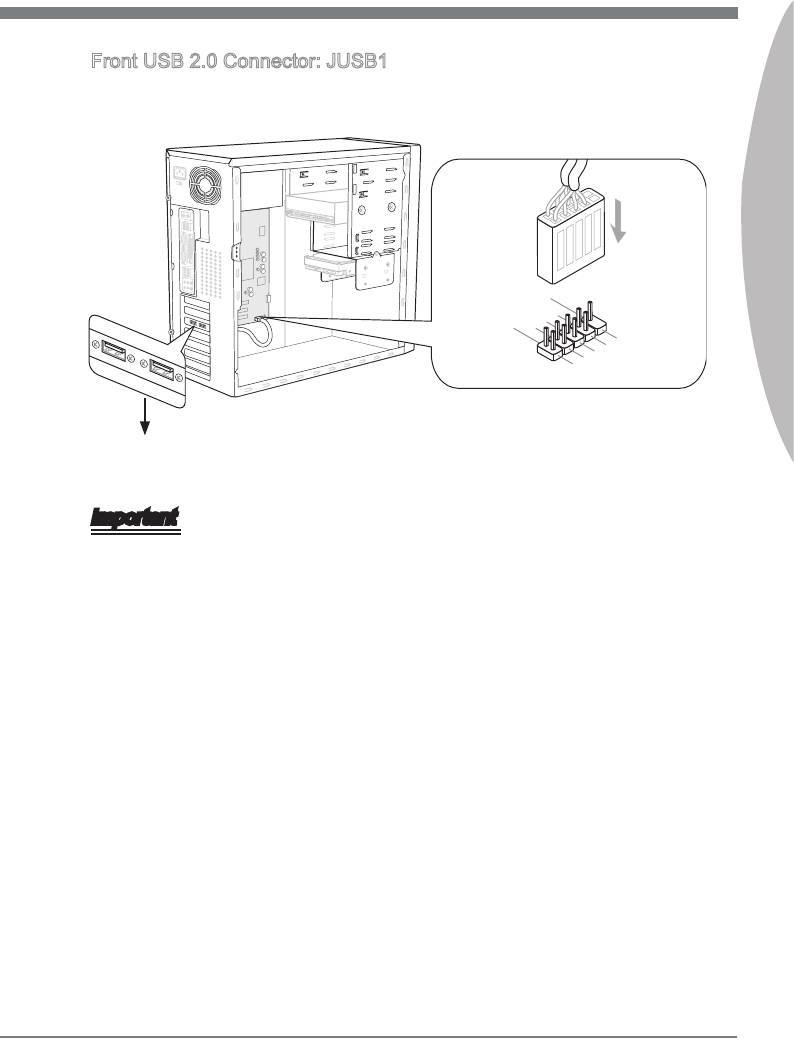
Front USB 2.0 Connector: JUSB1
®
Ths connector, complant wth Intel
I/O Connectvty Desgn Gude, s deal for con-
nectng hgh-speed USB nterface perpherals such as USB HDD, dgtal cameras, MP3
players, prnters, modems and the lke.
Englsh
En-17
11
5V
10.NC
8
6.USB 1
.Grou n d
4.USB 1
2.VC
+
C
-
9.No
7
5.USB 0
.Grou n d
Pin
3.USB 0
1.VC
+
C
-
* The MB layout n ths gure s for reference only.
USB Bracket (optonal)
Important
•
Note that the pns of VCC and GND must be connected correctly to avod possble
damage.
•
The JUSB1 (red mark) supports MSI newly Super-Charger technology. Wth Super-
Charger technology, the JUSB1 can only provde chargng functon n S0 (power-on),
S3 (sleep mode) & S5 (shut-down) states. However, the synchronzng data lnk wll
be dsabled. In ths case, the system can not be awaked through the JUSB1.
•
For Super-Charger n S3 (sleep mode)/ S5 (shut-down), we suggest you to connect
only one devce for stable chargng.
•
Super-Charger technology would be avalable on specc models, please refer to MSI
webste for model support lst.
MS-7681 Manboard
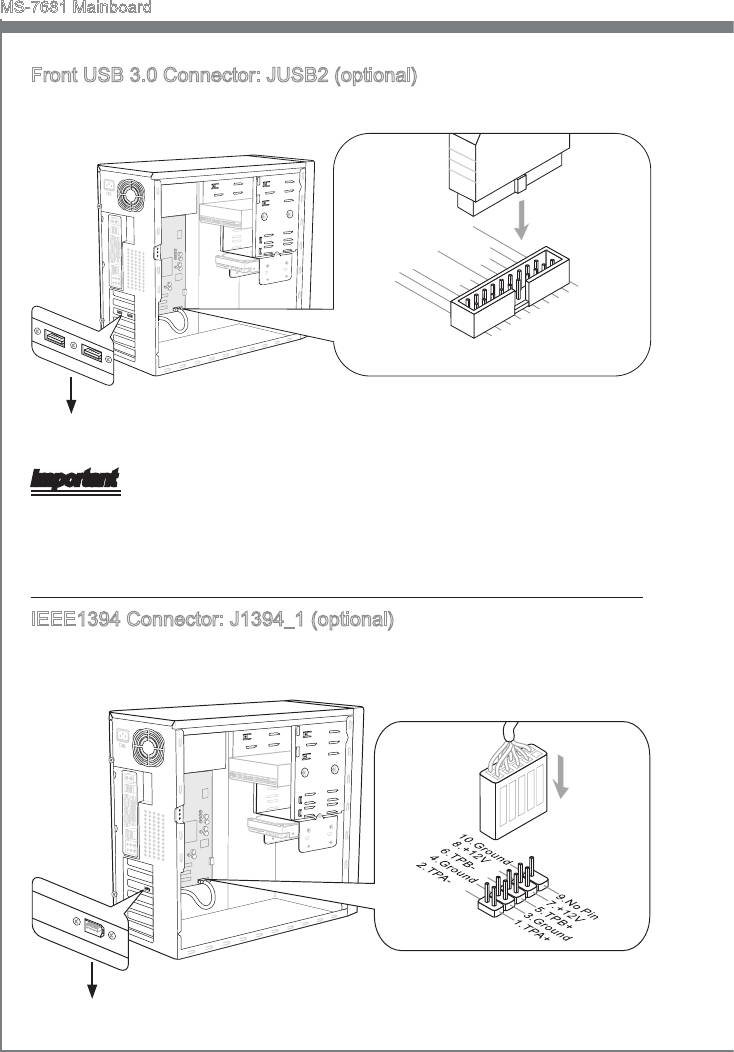
Front USB 3.0 Connector: JUSB2 (optonal)
USB 3.0 port s backward-compatble wth USB 2.0 devces. Supports data transfer rate
up to 5 Gbt/s (SuperSpeed).
En-18
1
15V
20.No
19.FUSB_VCC1
18.USB3_RX4_DN
17.USB3_RX4_DP
Pi
16.Ground
n
15.USB3_TX4_C_DN
14.USB3_TX4_C_DP
13.Ground
12.SBD1-
11
.
SBD1+
1
2.USB3_RX3_DN
.FUSB_VCC2
3.USB3_RX3_DP
4
5.
.Ground
6.USB3_TX3_C_DP
U
7
SB3_TX3_C_DN
8.SBD0-
.Ground
9.SBD0+
10.NC
* The MB layout n ths gure s for reference only.
USB 3.0 Bracket (optonal)
Important
•
Note that the pns of VCC and GND must be connected correctly to avod possble
damage.
•
If you want to use a USB 3.0 devce, you must use the USB 3.0 cable to connect to
the USB 3.0 port.
IEEE1394 Connector: J1394_1 (optonal)
Ths connector allows you to connect the IEEE1394 devce va an optonal IEEE1394
bracket.
* The MB layout n ths gure s for reference only.
1394 Bracket (optonal)
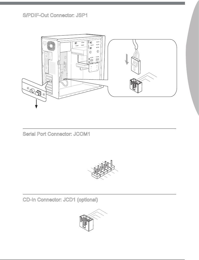
S/PDIF-Out Connector: JSP1
Ths connector s used to connect S/PDIF (Sony & Phlps Dgtal Interconnect Format)
nterface for dgtal audo transmsson.
Englsh
En-19
11
5V
1
.Ground
2.SPDIF
3.VC
C
* The MB layout n ths gure s for reference only.
S/PDIF-Out Bracket (optonal)
Seral Port Connector: JCOM1
Ths connector s a 16550A hgh speed communcaton port that sends/receves 16
bytes FIFOs. You can attach a seral devce.
1
0
8
.
.
N
6
C
o
.
D
T
P
4
S
S
i
.
n
2
D
R
.
T
S
R
I
N
9
.
7
R
.
R
I
5
3
.
G
T
.
S
1
S
r
o
.
D
O
u
C
U
n
T
d
D
CD-In Connector: JCD1 (optonal)
Ths connector s provded for external audo nput.
1
.
2
L
.
3
G
r
4
.
G
o
.
r
u
R
o
n
u
d
n
d
MS-7681 Manboard
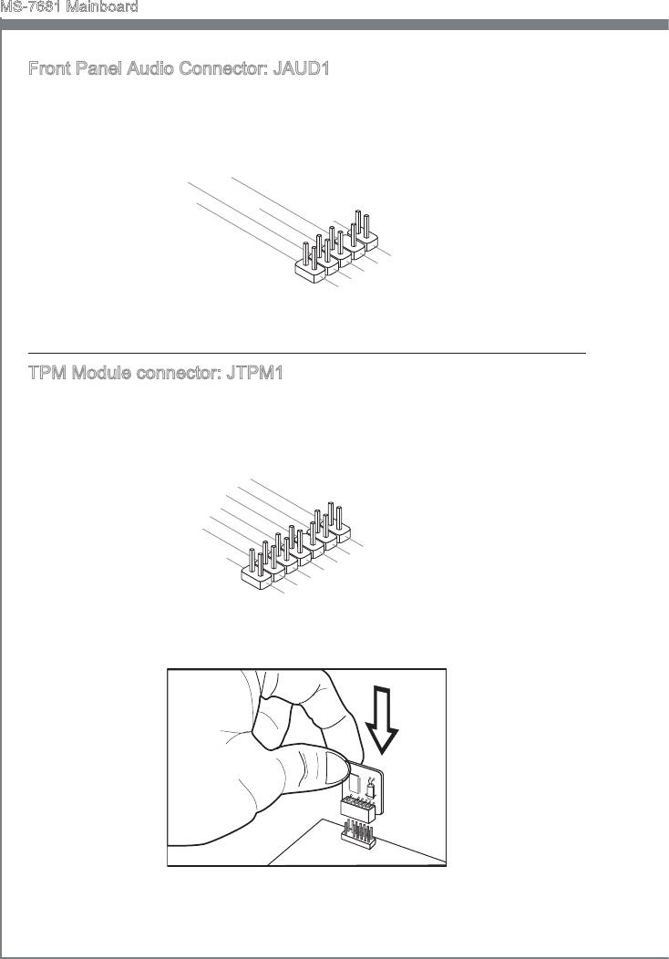
Front Panel Audo Connector: JAUD1
®
Ths connector allows you to connect the front panel audo and s complant wth Intel
Front Panel I/O Connectvty Desgn Gude.
En-20
10.Head
8.No
6.MI
4.NC
Pi
2
C D
P
n
hone
.Ground
etection
Detection
9.Head P
7.SENSE_SEN
5.Head P
3.MI
1.MI
hone
C R
C L
hone
L
D
R
TPM Module connector: JTPM1
Ths connector connects to a TPM (Trusted Platform Module) module (optonal). Please
refer to the TPM securty platform manual for more detals and usages.
1
1
4
.
G
1
2
0
.
G
r
o
8
.
N
r
u
.
o
n
6
5
o
u
d
.
V
P
n
4
S
d
.
e
P
i
n
3
o
2
r
.
i
.
3
a
w
3
V
l
e
V
I
r
P
R
S
o
Q
t
a
w
n
e
d
r
b
y
p
o
w
e
1
r
3
1
.
1
L
9
.
P
.
L
P
C
7
L
5
.
P
C
F
L
C
r
.
L
P
a
a
3
C
a
d
m
.
L
P
d
d
r
e
1
C
a
d
.
P
L
C
a
d
r
e
d
e
s
P
d
s
s
C
R
d
r
e
s
&
e
r
s
C
s
e
s
&
d
s
l
&
d
a
o
e
t
s
a
t
c
d
t
a
k
&
a
p
d
a
a
t
i
a
p
n
i
t
p
n
3
a
i
2
p
n
i
n
1
0
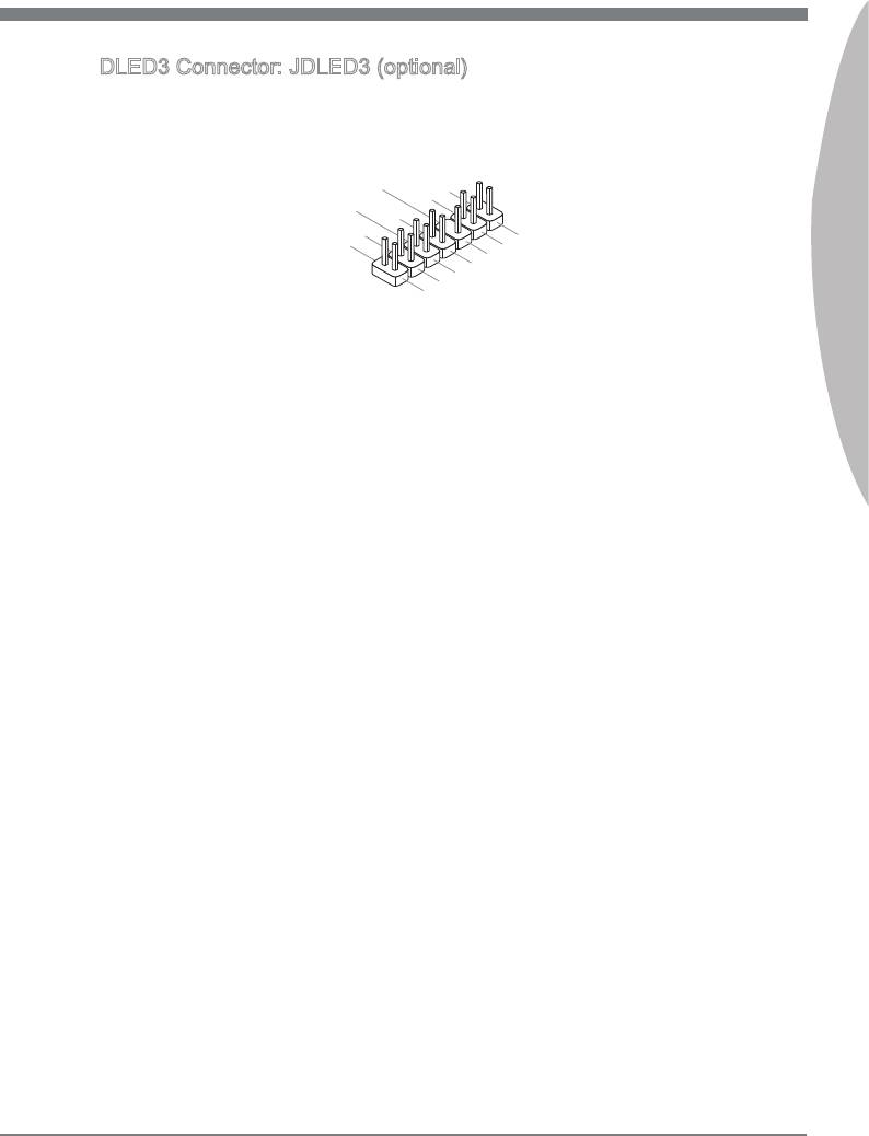
DLED3 Connector: JDLED3 (optonal)
Ths s reserved for connectng the ms future control card.
Englsh
En-21
14.Contro
12.Contro
10.No
8.Contro
6
Pi
l pin
.Ground
4.Contro
n
l p
2.Contro
in
l pin
l pin
l pin
13.Ground
11
9
.
.Ground
Reserve
7.Contro
5.Contro
3.Contro
1.5VSB
d p
l p
in
l pin
in
l p
in
MS-7681 Manboard
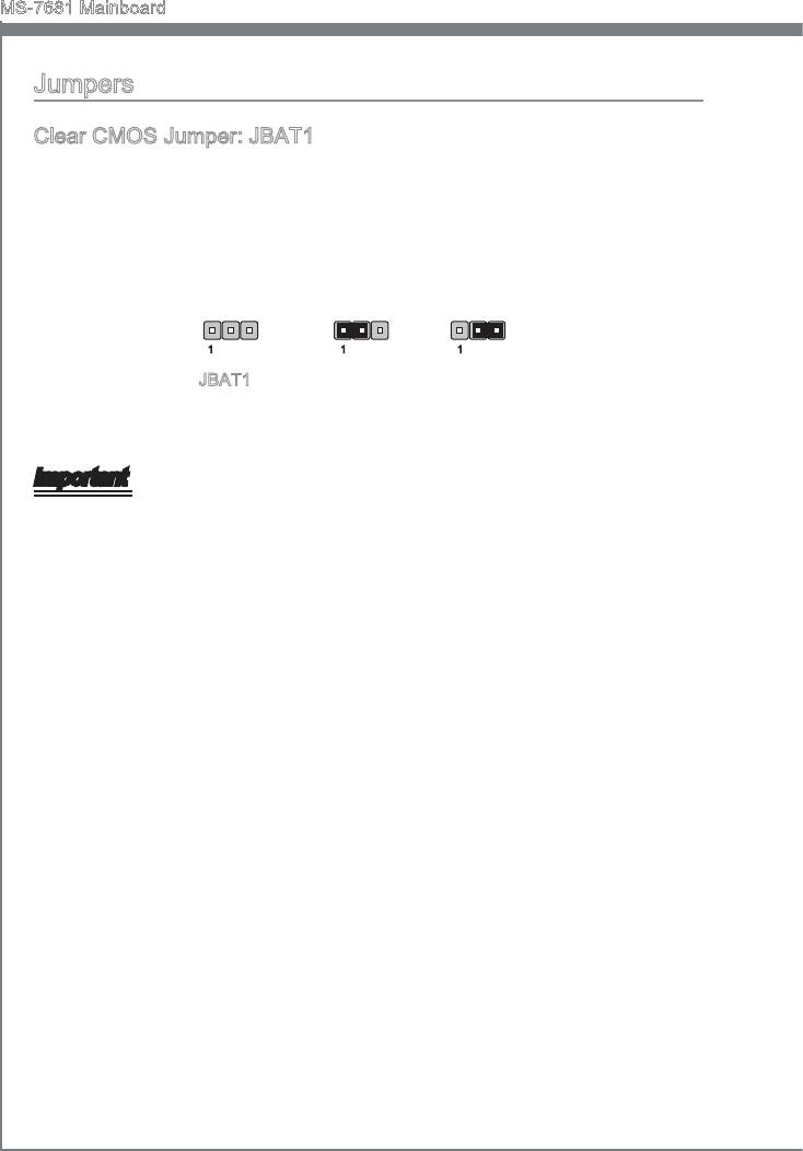
Jumpers
Clear CMOS Jumper: JBAT1
There s a CMOS RAM on board wth an external battery power supply to preserve the
system conguraton data. Wth the CMOS RAM, the system can automatcally boot OS
every tme t s turned on. If you want to clear the system conguraton, set the jumper
to clear data.
1 11
JBAT1 Keep Data Clear Data
Important
You can clear CMOS by shortng 2-3 pn whle the system s o. Then return to 1-
2 pn poston. Avod clearng the CMOS whle the system s on; t wll damage the
manboard.
En-22
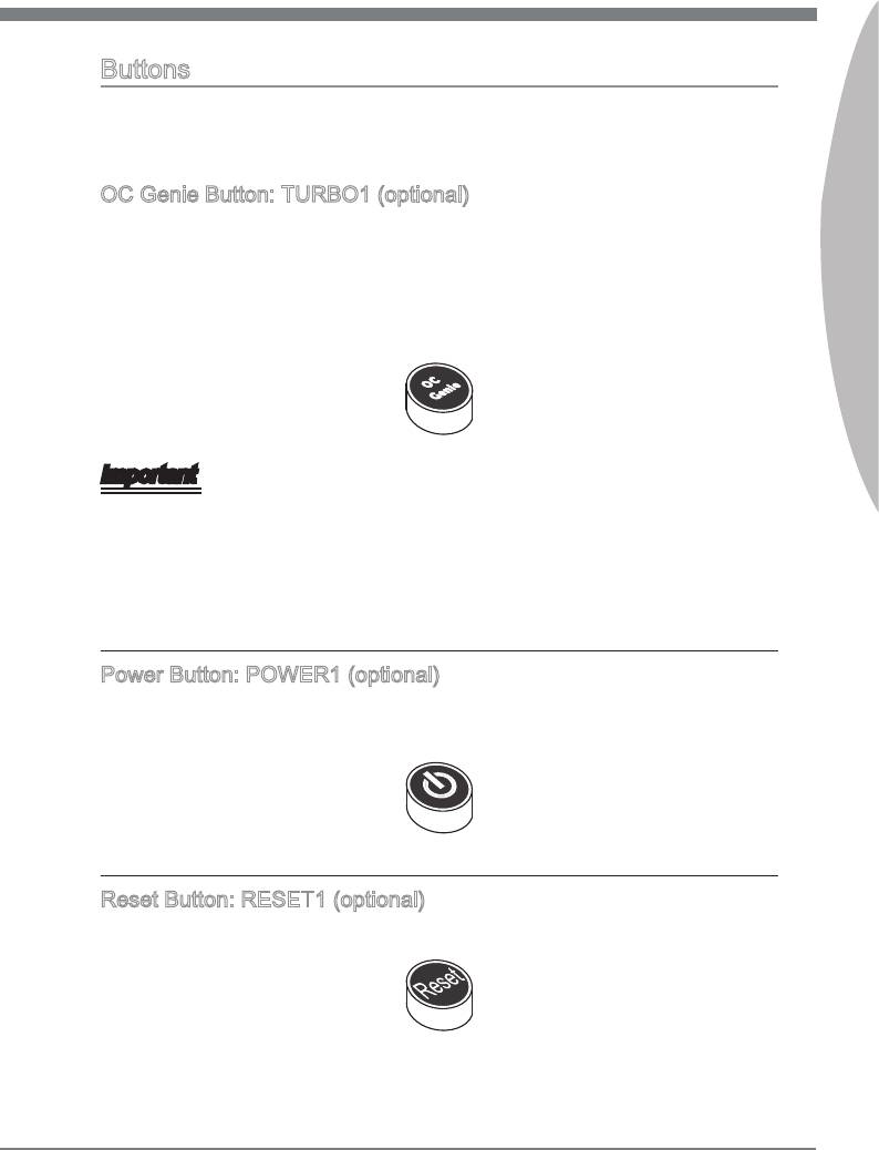
Buttons
Ths secton wll explan how to change your motherboard’s functon through the use of
followng buttons.
OC Gene Button: TURBO1 (optonal)
Englsh
Ths button s used to auto-overclock for the system. Press ths button to enable the
OC Gene functon when the system s n power o state, meanwhle, the button wll
lght and lock. And then the system wll automatcally detect the optmum values to
overclock after bootng the system. To dsable the OC Gene functon, please press the
button agan after power o the system, meanwhle, the button lght wll o and unlock,
and the system wll restore the default for next boot.
Important
Please nstall the DDR3 1333 and up memory and equp better heat snk/ cooler wth
OC Gene functon.
We do not guarantee the OC Gene overclockng range and the damages or rsks
caused by the OC Gene overclockng behavor.
You can dsable the OC Gene functon n BIOS setup. And we suggest you to save the
OC Gene conguraton to overclockng prole n BIOS for future usng.
Power Button: POWER1 (optonal)
Ths power button s used to turn-on or turn-o the system. Press the button to turn-on
or turn-o the system.
Reset Button: RESET1 (optonal)
Ths reset button s used to reset the system. Press the button to reset the system.
En-23
MS-7681 Manboard
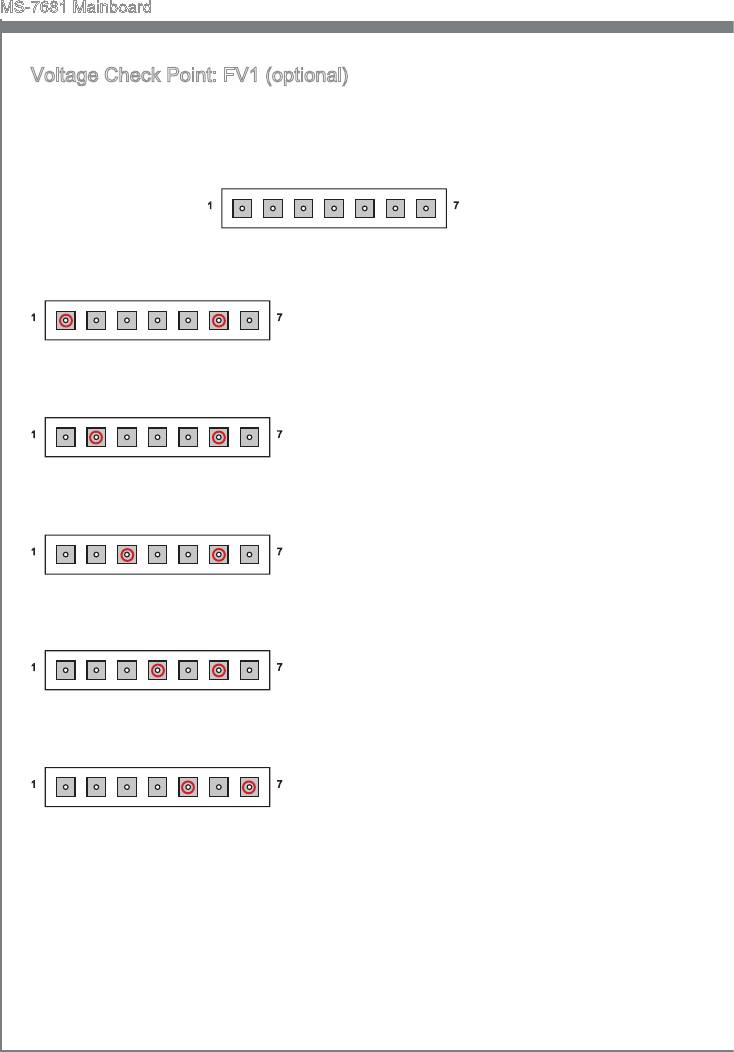
Voltage Check Pont: FV1 (optonal)
Ths voltage check pont set s used to measure the current CPU/ CPU_VTT/ CPU_SA/
DDR/ PCH voltage.
CPU
PCHCPU_SA
GND
1
7
CPU_VTT
DDR
GND
CPU voltage: measure the current CPU voltage
1
7
wth CPU pont and GND pont by usng a mul-
tmeter.
CPU
GND
CPU_VTT voltage: measure the current CPU_
1
7
VTT voltage wth CPU_VTT pont and GND
pont by usng a multmeter.
CPU_VTT
GND
CPU_SA voltage: measure the current CPU_SA
1
7
voltage wth CPU_SA pont and GND pont by
usng a multmeter.
CPU_SA
GND
DDR voltage: measure the current DDR voltage
1
7
wth DDR pont and GND pont by usng a mul-
tmeter.
DDR
GND
PCH voltage: measure the current PCH voltage
1
7
wth PCH pont and GND pont by usng a mul-
tmeter.
PCH
GND
En-24
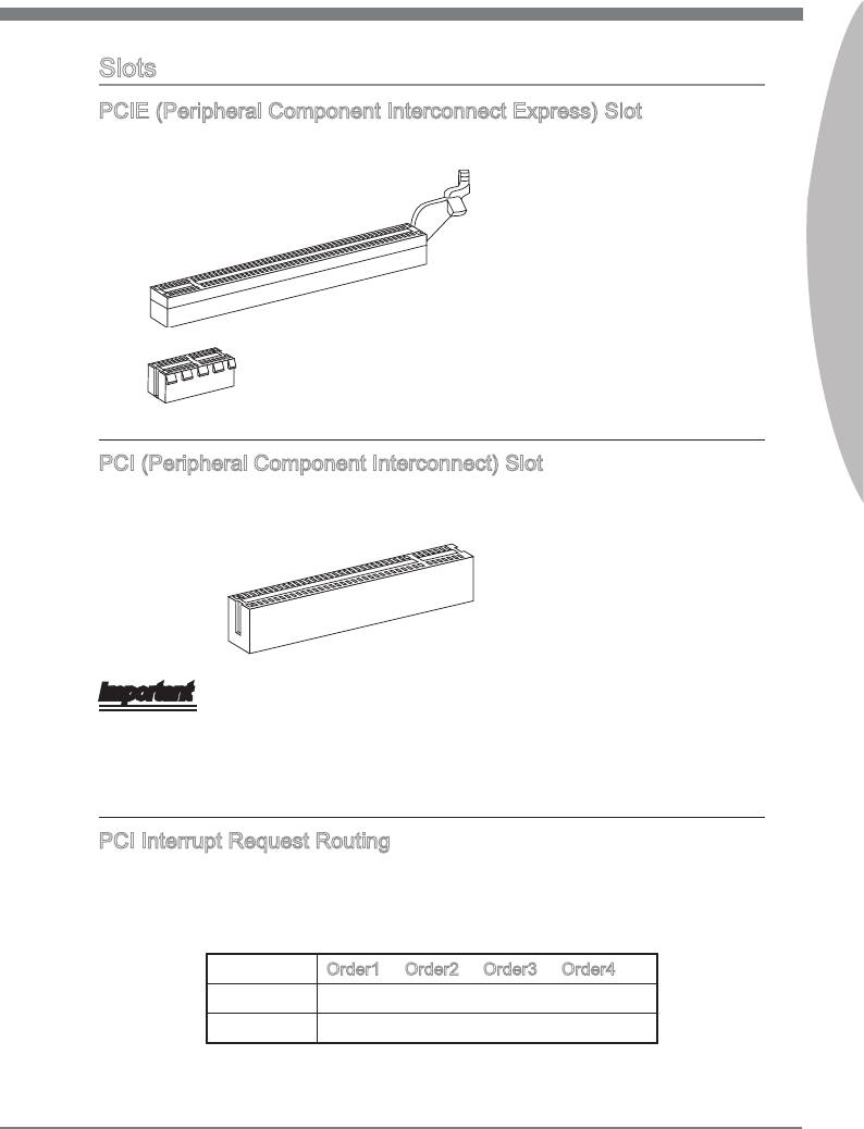
Slots
PCIE (Perpheral Component Interconnect Express) Slot
The PCIE slot supports the PCIE nterface expanson card.
Englsh
PCIE x16 Slot
PCIE x1 Slot
PCI (Perpheral Component Interconnect) Slot
The PCI slot supports LAN card, SCSI card, USB card, and other add-on cards that
comply wth PCI speccatons.
32-bt PCI Slot
Important
When addng or removng expanson cards, make sure that you unplug the power sup-
ply rst. Meanwhle, read the documentaton for the expanson card to congure any
necessary hardware or software settngs for the expanson card, such as jumpers,
swtches or BIOS conguraton.
PCI Interrupt Request Routng
The IRQ, acronym of nterrupt request lne and pronounced I-R-Q, are hardware lnes
over whch devces can send nterrupt sgnals to the mcroprocessor. The PCI IRQ pns
are typcally connected to the PCI bus pns as follows:
Order1 Order2 Order3 Order4
PCI Slot1 INT A# INT B# INT C# INT D#
PCI Slot2 INT B# INT C# INT D# INT A#
En-25
MS-7681 Manboard
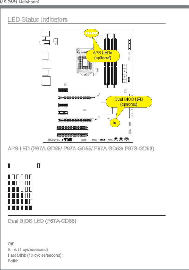
LED Status Indcators
APS LEDs
(optonal)
Dual BIOS LED
(optonal)
APS LED (P67A-GD65/ P67A-GD55/ P67A-GD53/ P67S-GD53)
The APS (Actve Phase Swtchng) LED ndcate the current CPU power phase mode.
Follow the nstructons below to read.
: Lghts : O
CPU s n 1 phase power mode.
CPU s n 2 phase power mode.
CPU s n 3 phase power mode.
CPU s n 4 phase power mode.
CPU s n 5 phase power mode.
CPU s n 6 phase power mode.
Dual BIOS LED (P67A-GD65)
The Dual BIOS LED ndcates the BIOS status durng system power on. Follow the
nstructons below to read.
O: Normal.
Blnk (1 cycle/second): The prmary BIOS s faled.
Fast Blnk (10 cycles/second): The second BIOS s faled.
Sold: Both of prmary and second BIOS are faled.
En-26
BIOS Setup
Ths chapter provdes basc nformaton on the BIOS Setup program and allows you to
congure the system for optmum use. You may need to run the Setup program when:
■
An error message appears on the screen durng the system bootng up, and
requests you to run BIOS SETUP.
■
You want to change the default settngs for customzed features.
Englsh
Important
•
The tems under each BIOS category descrbed n ths chapter are under contnuous
update for better system performance. Therefore, the descrpton may be slghtly df-
ferent from the latest BIOS and should be held for reference only.
•
Upon boot-up, the 1st lne appearng after the memory count s the BIOS verson. It s
usually n the format:
E7681IMS.xxx 102410 where:
1st dgt refers to BIOS type as E = EFI
2nd - 5th dgt refers to the model number.
6th dgt refers to the chpset as I = Intel, N = nVda, A = AMD and V = VIA.
7th - 8th dgt refers to the customer as MS = all standard customers.
xxx refers to the BIOS verson.
102410 refers to the date ths BIOS was released.
Enterng Setup
Power on the computer and the system wll start POST (Power On Self Test) process.
When the message below appears on the screen, press <DEL> key to enter Setup.
Press DEL to enter Setup Menu, F11 to enter Boot Menu
If the message dsappears before you respond and you stll wsh to enter Setup, restart
the system by turnng t OFF and On or pressng the RESET button. You may also re-
start the system by smultaneously pressng <Ctrl>, <Alt>, and <Delete> keys.
En-27
MS-7681 Manboard
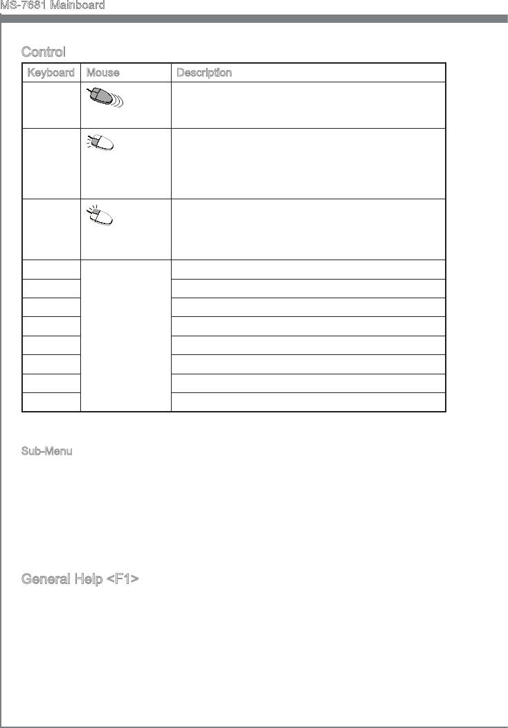
Control
Keyboard Mouse Descrpton
<↑ ↓ >
Select Item
Move the cursor
<Enter>
Select Icon/ Feld
Clck/ Double-
clck the left but-
ton
<Esc>
Jumps to the Ext menu or returns to the prevous from
a submenu
Clck the rght
button
<+> Increase the numerc value or make changes
<-> Decrease the numerc value or make changes
<F1> General Help
<F4> CPU Speccatons
<F5> Enter Memory-Z
<F6> Load optmzed defaults
<F10> Save Change and Reset
<Esc> Ext
Sub-Menu
If you nd a rght ponter symbol (as shown n the rght vew) appears to the left of cer
-
tan elds that means a sub-menu can be launched from ths eld. A sub-menu contans
addtonal optons for a eld parameter. You can use arrow keys ( ↑↓ ) or mouse to
hghlght the eld and press <Enter> or double-clck the left mouse button to enter the
sub-menu. Then you can use the control keys to enter values and move from eld to
eld wthn a sub-menu. If you want to return to the prevous menu, just press the <Esc
> or clck the rght mouse button.
General Help <F1>
The BIOS setup program provdes a General Help screen. You can call up ths screen
from any menu by smply pressng <F1>. The Help screen lsts the approprate keys to
use and the possble selectons for the hghlghted tem. Press <Esc> to ext the Help
screen.
En-28
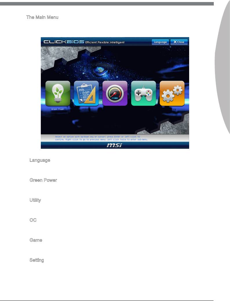
The Man Menu
Once you enter BIOS CMOS Setup Utlty, the Man Menu wll appear on the screen.
The Man Menu allows you to select from the setup functons.
Englsh
▶
Language
After enterng the Setup menu, you can see a “Language” button. Please clck t and
select the language, at your desre, for the BIOS settng rst.
▶
Green Power
Clck “Green Power” con to enter the menu. Use ths menu to specfy the power
phase.
▶
Utlty
Clck “Utlty” con to enter the menu. Ths menu provdes the useful utlty for you to lve
update bos and hard dsk backup.
▶
OC
Clck “OC” con to enter the menu. Use ths menu to specfy your settngs for frequency/
voltage control and overclockng.
▶
Game
Clck “Game” con to enter the menu. Ths menu provdes several games for you to
play.
▶
Settng
Clck “Settng” con to enter the menu. Use ths menu to specfy your settngs for chpset
features, boot devce and password.
En-29
MS-7681 Manboard
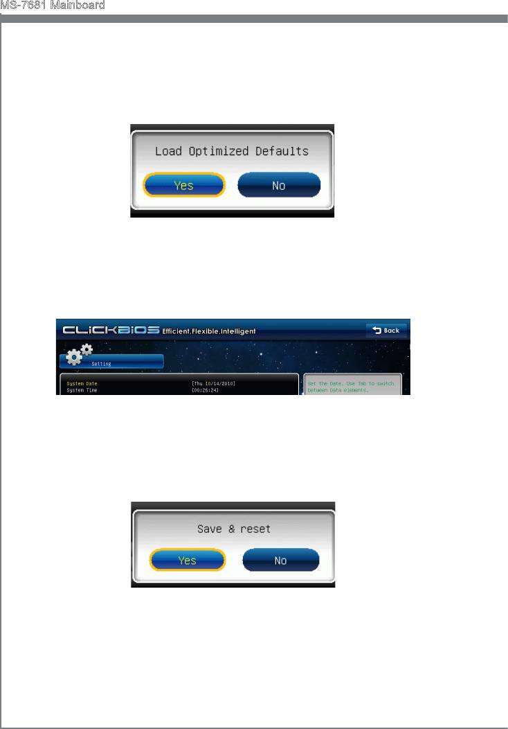
When enter the BIOS Setup utlty, follow the processes below for general use.
1.
Load Optmzed Defaults : Select [Settng] -> [Save & Ext] -> [Restore Defaults] and
clck on t. And then the screen shows a pop-up message as below. Select [Yes]
and clck on t to load the default settngs for optmal system performance.
2.
Setup Date/ Tme : Select [Settng] -> [System Status] -> [System Date]/ [System
Tme] and clck on t. And then, you can key-n the Date, Tme n ther respectve
elds.
3.
Save & Ext Setup : Select [Settng] -> [Save & Ext] -> [Save Changes & Reset]
and clck on t. And then the screen shows a pop-up message as below. Select
[Yes] and clck on t to save the conguratons and ext BIOS setup utlty.
En-30
")
")

