Labconco VACUUBRAND Diaphragm Pump 7393001: Use and operation
Use and operation: Labconco VACUUBRAND Diaphragm Pump 7393001
page 38 of 74
Installing a pump in a vacuum system
➨
If dangerous or polluting fluids could be released at the
outlet, install an appropriate system to catch and dis-
pose of those fluids.
+
Connect a gas-tight exhaust line at the pump outlet if
necessary. Always vent exhaust gases appropriately
(e.g., into a fume hood).
+
Never block the gas outlet. The exhaust line must al-
ways be free of obstructions (no back pressure) to en-
sure an unimpeded discharge of gas. The cross-sec-
tion of the outlet tubing must be at least the size of the
pump’s exhaust connection.
+
Particles and dust must not be aspirated. If necessary,
you must install appropriate filters. You must ensure
their suitability concerning gas flow, chemical resis
-
tance and resistance to clogging prior to use.
+
Make sure ventilation is adequate, especially if the pump
is installed in an enclosure, or if the ambient temperature
is elevated. Provide external ventilation, if necessary.
• Reduce the transmission of vibration. Prevent mechan
-
ical load due to rigid pipelines. Insert elastic hoses or
flexible elements as couplings between the pump and
rigid pipes.
Note
: Flexible elements will compress or
flatten when evacuated if not designed for use under
vacuum.
• Hose connections at the pump inlet must always be
gas tight.
• A power failure may cause accidental ventilation of the
pump, especially if the gas ballast valve is open . If this
constitutes a potential source of danger, take appropri-
ate safety measures.
Use and operation
page 39 of 74
Keep a distance of minimum 8 in (20 cm) between fan and
adjacent equipment or casework.
Use connecting hoses with large diameter and keep them
as short as possible to avoid flow losses. Locate the pump
as closely as possible to the application.
Always install outlet tubing descending from the pump to
avoid backflow of condensate towards the pump.
Use a suitable valve to isolate the pump from the vacuum
application. This is to allow the pump to warm up before
pumping condensable vapors and to clean the pump after
use before it is switched off.
When assembling, ensure
vacuum-tightness
. After as-
sembly, check the whole system for leaks.
Secure hose connections at the pump appropriately, e.g.,
with hose clamps, to protect against accidental detach-
ment.
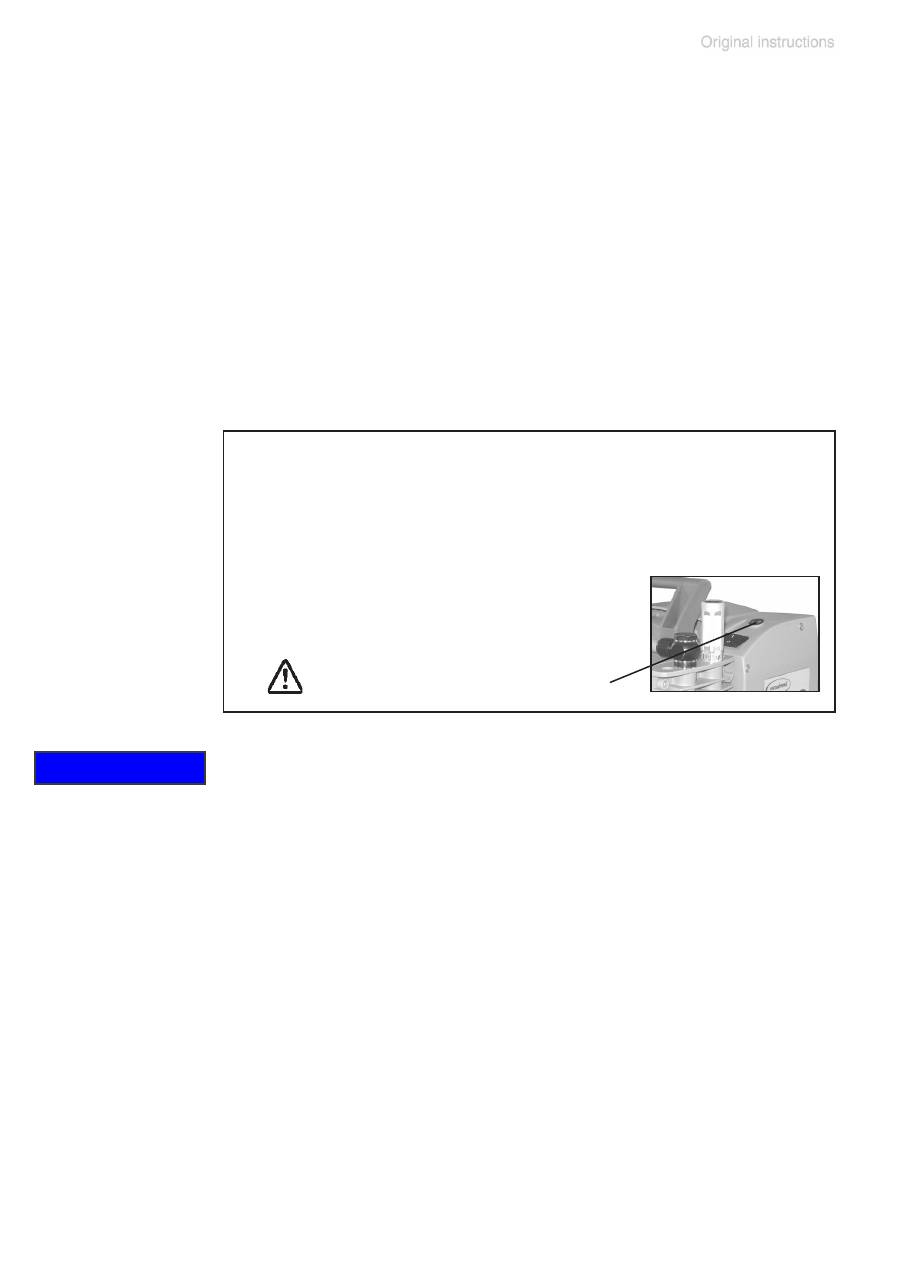
NOTICE
Voltage selection switch:
1. Disconnect the electrical power cord.
2. Use a screw driver to adjust the
voltage selec-
tion switch
at the terminal box of the pump to the
supply voltage:
”115” corresponds to 90-126 V and
”230” corresponds to 180-253 V.
voltage selection switch
• Check the power source and the pump’s rating plate
to be sure that the power source and the equipment
match in voltage, phase, and frequency.
•
Pump with dual-voltage motor
: Check that the volt-
age selection switch at the terminal box is positioned
correctly. Check every time before starting the pump.
Note
: If the pump is switched on with wrong voltage
selection, the motor may be damaged!
Change the selection at the voltage selection switch
only, if the pump is unplugged from the power
source.
page 40 of 74
To reduce pump noise emanating from the pump exhaust
port, connect an exhaust hose or use a silencer (see ”Ac-
cessories”, pg. 48).
Separator (inlet) and
exhaust waste vapor condenser (outlet)
Assembling the hose nozzle with union nut:
➨
Take the hose nozzle with attached compression fer-
rule and union nut out of the catchpot and put onto inlet
connection (version 2 AK: onto inlet and outlet connec-
tions).
➨
Tighten the union nut by hand until you can feel the
stop. Then tighten an additional 1/4 rotation with an
open-ended wrench (size 17mm) for final installation.
Catchpots:
The catchpot at the inlet protects against drop-
lets and particles from entering the pump.
+
Enhances lifetimes of diaphragms and
valves.
+
Improves vacuum performance in applica-
tions with condensable vapors.
Both catchpots are coated with a protective lay-
er to protect against shattering in case of break-
age or implosion.
➨
Assemble the catchpots at the inlet and at
the outlet using joint clips.
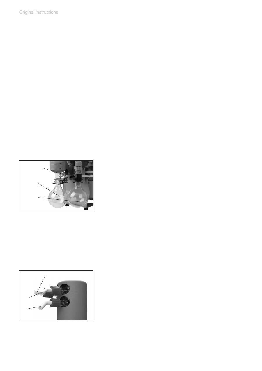
Exhaust waste vapor condenser:
➨
Assemble the hose nozzles for coolant inlet
(12) and coolant outlet (13) tubing at the ex-
haust waste vapor condenser.
The
exhaust waste vapor condenser
enables
an efficient condensation of the pumped vapors
at the outlet.
+
No backflow of condensates.
+
Controlled recovery of condensates.
+
Close to 100% solvent recovery.
+
The isolation cover protects against glass
overpressure
safety relief
device (11)
catchpot
at outlet (9)
catchpot
at inlet (9)
outlet (gas!) (2)
(12)
(13)
page 41 of 74
splinters in case of breakage, acts as ther-
mal isolation to avoid condensation of hu-
midity and is intended to absorb shocks.
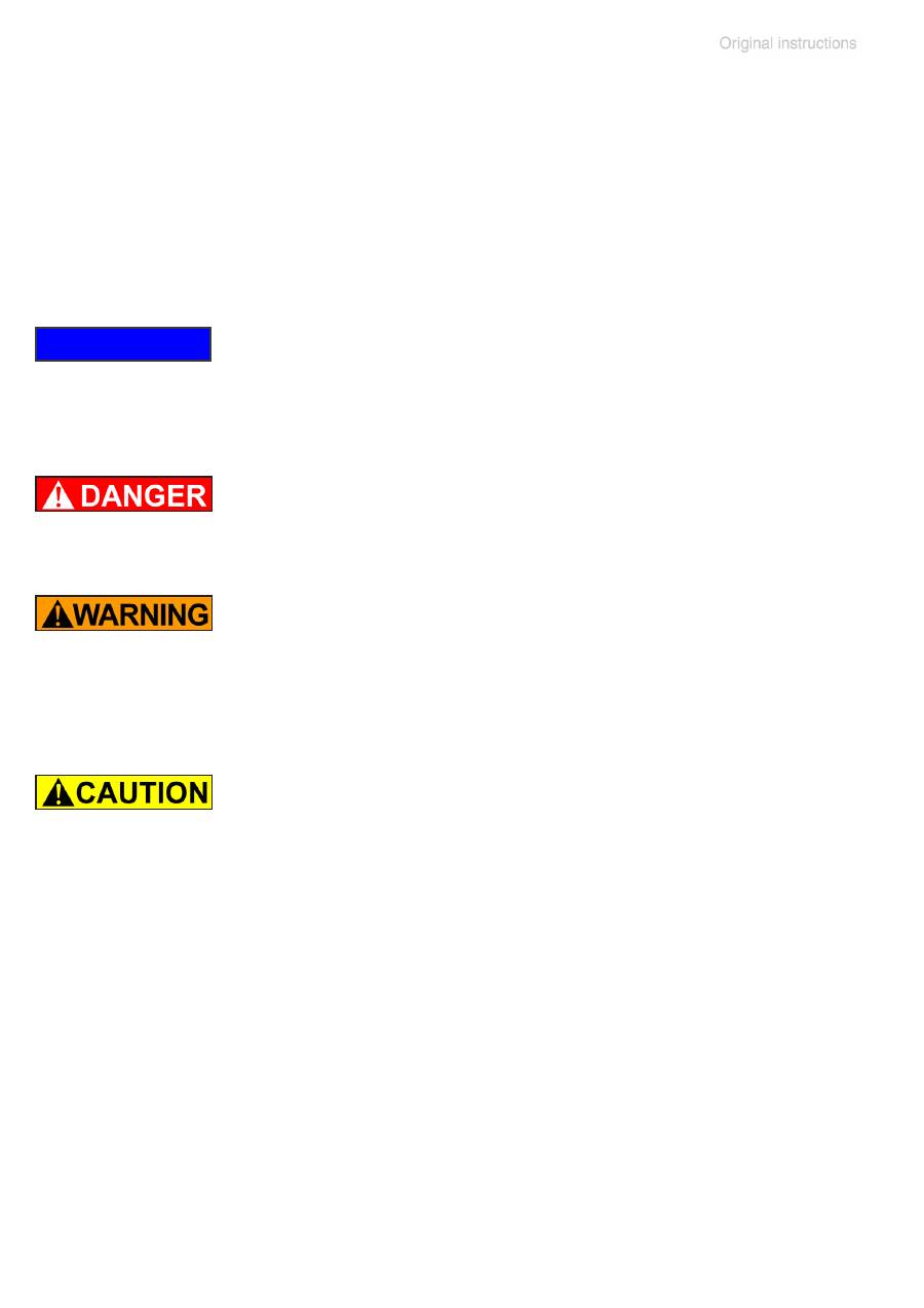
➨
Attach the tubing of the coolant circuit to the respective
hose nozzles (hose nozzles for tubing I.D. 1/4”-5/16”
(6-8 mm), see image) at the waste vapor condenser.
Check all hose connections prior to starting operation of
the cooling system.
Secure coolant hoses at the hose nozzles (e.g., with hose
clamps) to prevent their accidentally slipping off.
➨
Prevent the discharge of dangerous gases and vapors
to the surrounding atmosphere. If appropriate, connect
the exhaust line to a suitable treatment system.
+
Never block the gas outlet ((2) hose nozzle for tubing
I.D. 3/8” (10 mm)). The exhaust hose has always to be
unobstructed and without back pressure to enable an
unhindered discharge of gases and protect the pump
valves from damage.
•
Note
: Install the hoses of the cooling system in a way
to avoid the flow / dripping of condensed water onto the
pumping unit (especially cables and electronic parts,
see also IP degree of protection, ”Technical data”, pg.
24.
• Ensure that the
coolant outlet tubing
is always unob-
structed and that it cannot get blocked.
• Maximum permissible coolant pressure at the exhaust
waste vapor condenser: 87 psi (6 bar) absolute. Outlet
flow must always be unhindered.
• Comply with the maximum permissible coolant pres
-
sures of additional components in the coolant circuit
(e.g., coolant valve).
• Avoid overpressure in the coolant circuit (e.g., caused
by blocked or squeezed coolant hoses).
• Only install the optional coolant valve in the supply line
of the exhaust waste vapor condenser.
NOTICE
page 42 of 74
During operation
➨
Vent and dispose of
potentially dangerous gases or
vapors
at the outlet of the pump appropriately.
+
Due to the high compression ratio, the pump might gen-
erate overpressure at the outlet. Check pressure com-
patibility with system components (e.g., exhaust tubing
or exhaust valve) at the outlet. Ensure that the pump
outlet is neither blocked nor restricted.
+
Maximum ambient temperature
: 104 °F (40 °C)
Check the maximum temperatures, if installing the
pump in a cabinet or a housing. Make sure ventilation
is adequate, especially if the ambient temperature is
elevated.
• If the pump is installed at an altitude of more than 3300
ft (1000 m) above mean sea level, check compatibil-
ity with applicable safety requirements, especially IEC
60034. There is a risk of the motor overheating due to
insufficient cooling.
• Check compatibility with the
maximally permitted
pressure
at outlet and the
maximum pressure differ-
ence
between inlet and outlet ports.
Do not start the pump if the
pressure difference between
inlet and outlet ports exceeds max. 16.0 psi (1.1 bar)
.
Attempts to start the pump at higher pressure difference
may cause stalling and damage of the motor.
If pumping condensable vapors (water vapor, solvents,
etc.), let the pump run with
gas ballast
to help purge any
condensation in the pump.
Prevent internal condensation, transfer of liquids or dust.
The diaphragms and valves will be damaged, if liquids are
pumped in significant amounts.
Check the pump regularly for external soiling and depos-
NOTICE
page 43 of 74
its. Clean the pump if necessary to avoid an increase of
the pump’s operating temperature.
Operation with silencer (optional) at the outlet: Operating
the pump at a high inlet pressure or pumping dusty gases
for a long time may cause clogging of the silencer. Check
the silencer regularly and replace if necessary.
In case of overload, the motor is shut down by a
self-hold
thermal circuit breaker
in the winding.
Note
: Only a manual reset is possible. Switch off the
pump and disconnect the electrical power cord. Identify
and eliminate the cause of failure. Wait approximately five
minutes before restarting the pump.
•
Note
: In case of
supply voltage below 100V
, the lock
of the breaker may not latch and the pump might restart
on its own after sufficient cooling. Take appropriate pre
-
cautions, if an automatic restart of the pump may lead
to a dangerous situation.
A warm up period (approximately 15 min.) is required to
ensure that the rated ultimate vacuum and pumping speed
are attained. Avoid overheating (e.g., due to hot process
gases).
Pumps with flow control diaphragm valve:
Use the flow control diaphragm valve (14) at the pump
inlet to control the pumping speed. Open flow control
diaphragm to pump down.
➨
Opening the flow control diaphragm: Turn counterclock
-
wise. Do not attempt to open the valve further than when
resistance is first encountered.
➨
Closing: Turn clockwise. Close flow control diaphragm
valve slightly hand-tight. Further tightening will not in-
crease sealing of the valve, and may lead to damage.
Note
: Over-tightening or -loosening may damage the dia-
phragm or the valve seat, and the valve may not close
properly thereafter.
Replace diaphragm in case of leaks.
NOTICE
NOTICE
page 44 of 74
Important notes regarding the use of gas bal-
last
Gas ballast is a continuous purge to keep the pump’s in-
terior as clean as possible and to reduce the possibility of
condensation inside the pump.
➨
Air and pumped media might react inside the pump or
at the outlet of the pump and form hazardous or explo-
sive mixtures, when you use air rather than inert gas
for the gas ballast. This constitutes a risk of significant
damage to equipment and/or facilities, a risk of person-
al injury or even loss of life.
+
Make sure that air/gas intake through the gas ballast
valve can never lead to hazardous, explosive or other-
wise dangerous mixtures. If in doubt, use inert gas.
To reduce condensation in the pump, do not pump vapor
before the pump has reached its operating temperature.
Open the gas ballast valve when pumping condensable
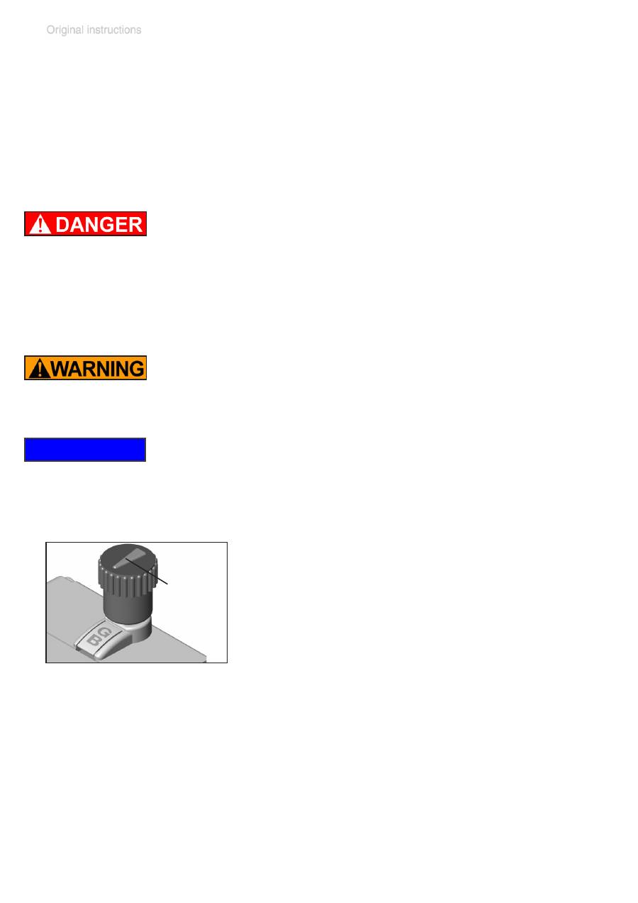
vapors. Turn gas ballast cap to open valve.
For
condensable vapors
(water vapor, sol-
vents, etc.):
- The gas ballast valve is open if the arrow on
the gas ballast cap is pointing towards the
labelling ”GB”.
- With gas ballast valve open, the ultimate
vacuum will be reduced.
- Use inert gas for gas ballast to avoid the formation of
explosive mixtures. A special adapter fitting is needed
to connect an inert gas supply line (see ”Accessories”,
pg. 48). This adapter replaces the standard gas bal-
last cap and allows for an inert gas line to be connected
via a KF DN 16 small flange at a maximum supply pres
-
sure of 17.5 psi (1.2 bar) absolute.
- Close the gas ballast valve by turning the cap 180°.
NOTICE
gas ballast
(3)
(open)
page 45 of 74
In case of low boiling solvents (when the formation of con-
densate is unlikely), the use of gas ballast might be unnec-
essary. Operating the pump without gas ballast increases
the solvent recovery rate at the exhaust waste vapor con-
denser.
Important notes concerning the operation of
the exhaust waste vapor condenser
➨
Connect the exhaust to a suitable treatment system to
prevent the discharge of dangerous gases and vapors
to the surrounding atmosphere.
+
Never block the gas outlet ((2) hose nozzle for tubing
I.D. 3/8” (10 mm)). The exhaust hose must always be
unobstructed and without back-pressure to enable an
unhindered discharge of gases.
+
Check the overpressure safety relief device (11) at the
exhaust waste vapor condenser (10) regularly; replace
if necessary. Check especially for deterioration, coales-
cence and cracks.
• Ensure that the
coolant outlet hose
is always free and
that it cannot get blocked.
• Maximum permissible coolant pressure at the exhaust
waste vapor condenser: 87 psi (6 bar) absolute
• Comply with the maximum permissible coolant pres
-
sures of additional components in the coolant circuit
(e.g., coolant valve).
• We strongly recommend installing an optional coolant
valve (see ”Accessories”, pg. 48)
in the supply line
of the exhaust vapor condenser to save water and re-
duce the risk of water spill.
• Avoid overpressure in the coolant circuit (e.g., caused
by blocked or kinked coolant hoses).
In case of
condensation
: Check the liquid level in both
catchpots (9) during operation. Check the liquid level in
both catchpots regularly. Do not allow the catchpots to
NOTICE

page 46 of 74
overfill. Drain catchpots in time to avoid overflow. Install a
level sensor (see ”Accessories”, pg. 48) for monitoring,
if necessary (VACUUBRAND controller CVC 3000 or VNC
2 is required).
The maximum liquid level is at approximately 80% of the
total filling level to avoid problems when removing the
catchpots.
Permissible range of coolant temperature at the exhaust
waste vapor condenser:
5 °F to 68 °F (-15°C to +20°C)
Check hose connections prior to starting operation of the
cooling system.
Check coolant hoses regularly during operation.
Removing the catchpots:
Catchpot at outlet:
Remove joint clip. Remove catchpot and drain conden-
sate.
Catchpot at inlet:
Admit air or inert gas (via the pump inlet) to restore at-
mospheric pressure in the catchpot before attempting
removal.. Remove joint clip. Remove catchpot and drain
condensate.
Reattach drained catchpots.
+
Important
: Comply with regulations when disposing
of solvents/condensates. Recycle if possible; purify if
contaminated.
NOTICE

page 47 of 74
Shutdown & storage
The pump can be switched off under vacuum.
Short-term:
Has the pump been exposed to condensate?
Allow the pump to continue to run at atmospheric pres-
sure for a few minutes.
Has the pump been exposed to media which may damage
the pump materials or form
deposits
?
Check and clean pump heads if necessary.
Long-term:
Take measures as described above regarding short-term
shutdown.
Separate the pump from the application.
Close inlet and outlet ports (e.g., with transport caps).
Close the gas ballast valve.
Drain catchpots.
Store the pump under dry conditions.
NOTICE
