Labconco VACUUBRAND Diaphragm Pump 7393001: Technical data
Technical data: Labconco VACUUBRAND Diaphragm Pump 7393001
page 24 of 74
Technical data
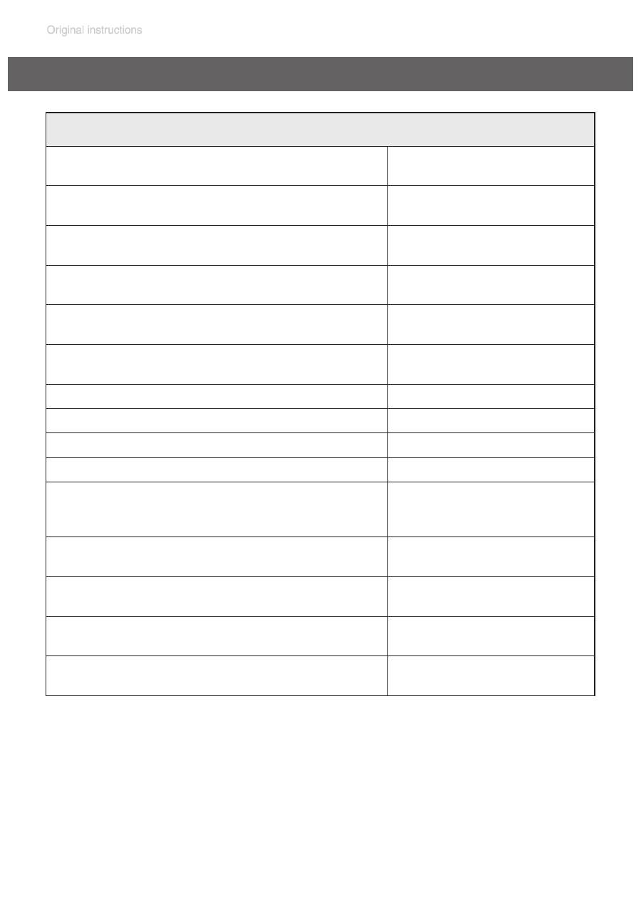
General technical data valid for all pumps/pumping units
Maximum permissible inlet pressure
(absolute)
psi
(bar)
16
(1.1)
Maximum permissible outlet pressure
(absolute)
psi
(bar)
16
(1.1)
Maximum pressure difference between
inlet and outlet
psi
(bar)
16
(1.1)
Maximum permissible pressure (abso-
lute) at gas ballast valve
psi
(bar)
17.5
(1.2)
Permissible ambient temperature
storage / operation
°F
(°C)
14 to 140 / 50 to 104
(-10 to +60 / +10 to +40)
Permissible relative atmospheric mois-
ture during operation (no condensation)
%
30 to 85
No-load speed 50/60 Hz
rpm
1500 / 1800
Device fuse
slow blow fuse 6.3 A
Motor protection
thermal cutout, manual reset
Degree of protection IEC 529
IP 40
Coolant connection
(waste vapor condenser, only ”EK”)
hose nozzle for tubing
I.D. 1/4” - 5/16”
(hose nozzle DN 6-8 mm)
Maximum permissible pressure of
coolant at waste vapor condenser (”EK”)
psi
(bar)
87 (absolute)
(6 (absolute))
Permissible range of coolant temperature
(waste vapor condenser, only ”EK”)
°F
(°C)
5 to 68
(-15 to +20)
Volume of catchpot (only ”AK” / ”EK”)
quarts
(ml)
0.52
(500)
A-weighted emission sound pressure
level* (uncertainty K
pA
: 3 dB(A))
dB(A)
45
* Measurement according to EN ISO 2151:2004 and EN ISO 3744:1995 at 230V/50Hz and ulti-
mate vacuum with exhaust tube at outlet.
page 25 of 74
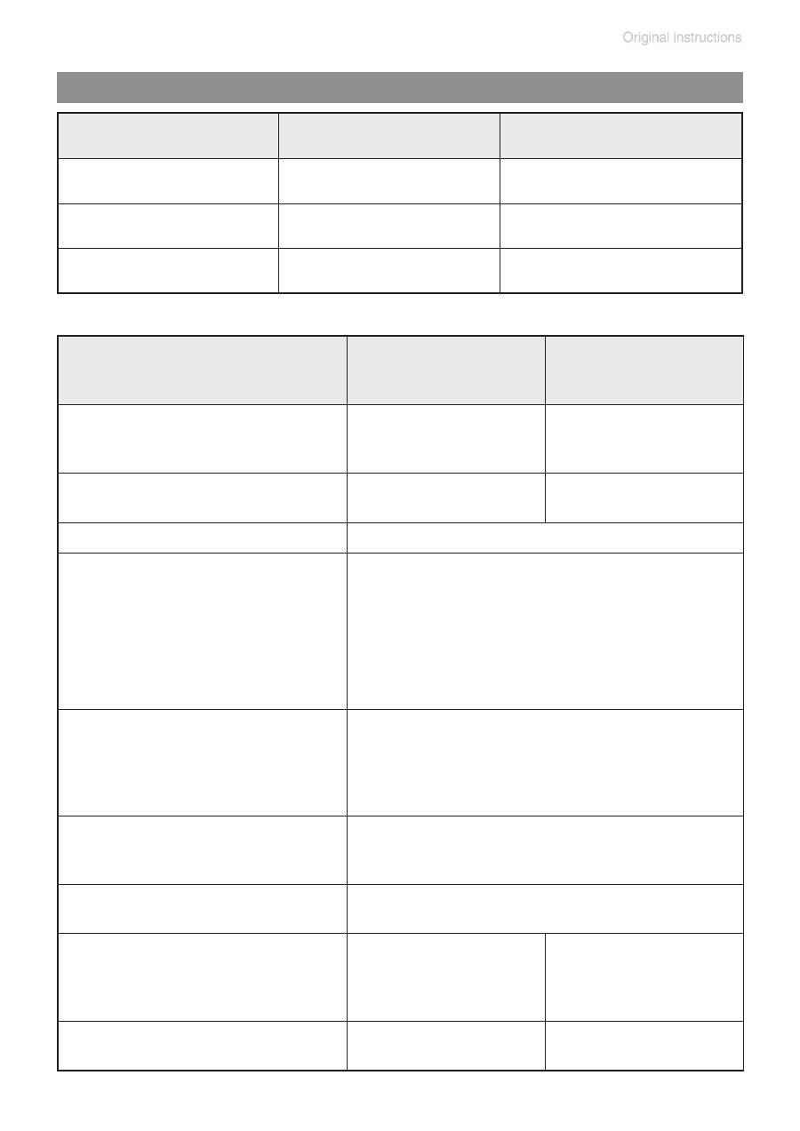
Gas inlet temperatures
Type
ME 2C NT
ME 4C NT
ME 4C NT + 2 AK
Maximum pumping
speed* 50/60 Hz
(ISO 21360)
cfm
(m
3
/h)
1.2 / 1.4
(2.1 / 2.4)
2.3 / 2.6
(3.9 / 4.3)
Ultimate vacuum
(absolute)
Torr
(mbar)
52.5
(70)
52.5
(70)
Rated motor power
hp (kW)
0.24 (0.18)
Maximum permissible range
of supply voltage ( ±10% )
Attention: Observe specifications
of rating plate!
100-115 V~ 50/60 Hz, 120V~ 60 Hz
230 V~ 50/60 Hz
Dual voltage motor
100-115 V~ 50/60 Hz, 120~ V 60 Hz /
200-230 V~ 50/60 Hz
Maximum rated current at:
100-115 V~ 50/60 Hz, A
120 V~ 60 Hz
200-230 V~ 50/60 Hz A
230 V~ 50/60 Hz A
3.4
1.8
1.8
Inlet
hose nozzle for tubing I.D. 3/8" or small flange
KF 16 (hose nozzle DN 10 mm or small flange
KF 16)
Outlet
hose nozzle for tubing I.D. 3/8”
(hose nozzle DN 10 mm)
Dimensions L x W x H
approx.
design 2 AK
in
(mm)
in
(mm)
9.6 x 8.3 x 7.8
(243 x 211 x 198
-
(-)
10.0 x 9.6 x 7.8
(254 x 243 x 198)
12.4 x 9.6 x 11.5
(316 x 243 x 291)
Weight approx.
design 2 AK
lbs. (kg)
lbs. (kg)
22.5 (10.2)
-
24.3 (11.1)
30.0 (13.6)
* Pumping speed of diaphragm pump
Operating condition
Inlet pressure
Permitted range of gas
temperatures at inlet
Continuous operation
> 75 Torr (100 mbar)
(high gas load)
➨
50 °F to 104 °F
(+10°C to +40°C)
Continuous operation
< 75 Torr (100 mbar)
(low gas load)
➨
32 °F to 140 °F*
(0°C to +60°C*)
Short-time
(< 5 minutes)
< 75 Torr (100 mbar)
(low gas load)
➨
14 °F to 176 °F*
(-10°C to +80°C*)
* if pumping potentially explosive atmospheres: 50 °F to 104 °F (+10°C to +40°C)
page 26 of 74
* Pumping speed of diaphragm pump
Type
MZ 2C NT
MZ 2C NT + 2 AK
MZ 2C NT + AK + EK
MZ 2C NT + AK SYNCHRO + EK
MZ 2C NT + AK + M + D
PC 101 NT
Maximum pumping speed*
50/60 Hz (ISO 21360)
cfm
(m
3
/h)
1.2 / 1.4
(2.0 / 2.3)
Ultimate vacuum (absolute)
without gas ballast
Torr
(mbar)
5.3
(7)
Ultimate vacuum (absolute)
with gas ballast
Torr
(mbar)
9
(12)
Rated motor power
hp (kW)
0.24 (0.18)
Maximum permissible range
of supply voltage ( ±10% )
Attention: Observe specifications
of rating plate!
Dual voltage motor
100-115 V~ 50/60 Hz, 120V~ 60 Hz
230 V~ 50/60 Hz
100-115 V~ 50/60 Hz, 120 V 60 Hz /
200-230 V~ 50/60 Hz
Maximum rated current at:
100-115 V~ 50/60 Hz,
120 V~ 60 Hz
200-230 V~ 50/60 Hz
230 V~ 50/60 Hz
A
A
A
3.4
1.8
1.8
Inlet
hose nozzle for tubing I.D. 3/8" or small
flange KF 16 (hose nozzle DN 10 mm
or small flange KF 16)
Outlet
hose nozzle for tubing I.D. 3/8”
(hose nozzle DN 10 mm)
Dimensions L x W x H approx.
Pump:
Vacuum systems:
design 2 AK
design AK + EK design
AK SYNCHRO + EK
design AK + M + D
PC 101 NT
in (mm)
in (mm)
in (mm)
in (mm)
in (mm)
in (mm)
9.6 x 9.6 x 7.8 (243 x 243 x 198)
12.6 x 9.6 x 12.2 (319 x 243 x 309)
12.8 x 9.6 x 15.8 (326 x 243 x 402)
12.8 x 9.8 x 15.8 (326 x 248 x 402)
12.2 x 9.6 x 12.3 (310 x 243 x 313)
12.8 x 9.6 x 15.8 (326 x 243 x 402)
Weight approx.
Pump:
Vacuum systems:
design 2 AK
design AK + EK
design AK SYNCHRO + EK
design AK + M + D
PC 101 NT
lbs. (kg)
lbs. (kg)
lbs. (kg)
lbs. (kg)
lbs. (kg)
lbs. (kg)
24.3 (11.1)
30.0 (13.6)
31.3 (14.2)
32.0 (14.5)
29.5 (13.4)
32.0 (14.5)
page 27 of 74
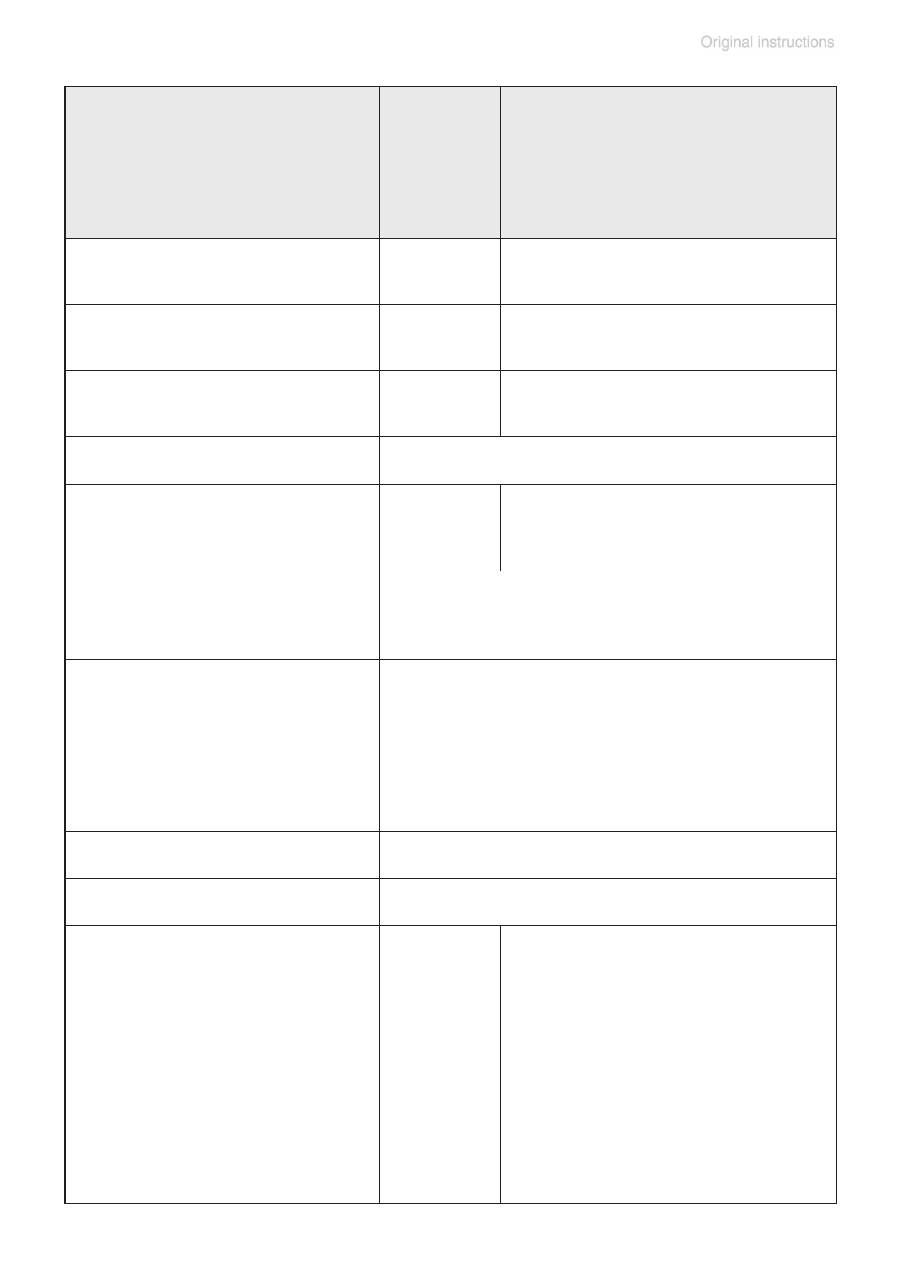
* Pumping speed of diaphragm pump
Type
ME 8C NT
ME 8C NT
+ 2 AK
MD 4C NT
MD 4C NT + 2 AK
MD 4C NT + AK + EK
MD 4C NT +
AK SYNCHRO + EK
PC 201 NT
Maximum pumping
speed* 50/60 Hz
(ISO 21360)
cfm
(m
3
/h)
4.0 / 4.6
(7.1 / 7.8)
2.0 / 2.2
(3.4 / 3.8)
Ultimate vacuum
(absolute)
without gas ballast
Torr
(mbar)
52.5
(70)
1.1
(1.5)
Ultimate vacuum
(absolute)
with gas ballast
Torr
(mbar)
-
2.3
(3)
Rated motor power
hp (kW)
0.34 (0.25)
Maximum permissible range of
supply voltage ( ±10% )
Note: Observe specifications of
rating plate!
100 V~
50/60 Hz
120 V~ 60 Hz
100-115 V~ 50/60Hz,
120 V~ 60 Hz
-
Dual voltage motor
230 V~ 50/60 Hz
100-115 V~ 50/60 Hz, 120 V~ 60 Hz /
200-230 V~ 50/60 Hz
Maximum rated cur-
rent at:
100 V~ 50/60 Hz
120 V~ 60 Hz
100-115 V~ 50/60 Hz,
120V~ 60 Hz
200-230 V~ 50/60 Hz
230V~ 50/60 Hz
A
A
A
A
A
5.0
4.0
5.7
3.0
3.0
Inlet
hose nozzle for tubing I.D. 3/8"
(hose nozzle DN 10 mm)
Outlet
hose nozzle for tubing I.D. 3/8"
(hose nozzle DN 10 mm)
Dimensions L x W x H
approx.
Pump:
Vacuum systems:
design 2 AK
design AK + EK
design
AK SYNCHRO + EK
PC 201 NT
in (mm)
in (mm)
in (mm)
in (mm)
in (mm)
12.8 x 9.6 x
7.8
(325 x 243
x 198)
12.6 x 9.6 x
14.7 (319 x
243 x 374)
-
-
-
12.8 x 9.6 x 7.8 (325 x 243 x 198)
12.6 x 9.6 x 14.7 (319 x 243 x 374)
12.8 x 9.6 x 15.8 (326 x 243 x 402)
12.8 x 9.8 x 15.8 (326 x 248 x 402)
12.8 x 9.6 x 15.8 (326 x 243 x 402)
page 28 of 74
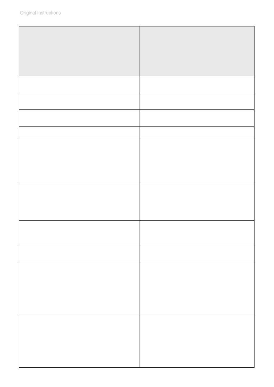
Components
Wetted materials
Head cover
ETFE carbon fiber reinforced
Diaphragm clamping disc
ETFE carbon fiber reinforced
Diaphragm
PTFE
Valves (ME 2C NT / ME 4C NT / ME 8C NT) PTFE
Valves (MZ 2C NT / MD 4C NT)
FFKM
O-rings
FPM
Valve head
ECTFE carbon fiber reinforced
Gas ballast tube
PTFE carbon reinforced
Inlet (hose nozzle)
Pump
Vacuum systems
Inlet (small flange)
PTFE carbon reinforced
PP (PBT only SYNCHRO designs)
stainless steel
Outlet (hose nozzle)
Pump / MZ 2C NT + AK + M + D
Vacuum systems (waste vapor condenser)
Vacuum systems (2 AK)
PTFE carbon reinforced
PET
PP
Tubing
PTFE
Flow control diaphragm
PTFE
Valve block (SYNCHRO design)
PP
Valves (valve block SYNCHRO)
FFKM
Distribution head
PPS glass fiber reinforced
Blind plug
PP
O-ring at catchpot
FPM
Overpressure safety relief device
PTFE / silicone rubber
Exhaust waste vapor condenser / catchpot
Borosilicate glass
Wetted parts
Type
ME 8C NT
ME 8C NT
+ 2 AK
MD 4C NT
MD 4C NT + 2 AK
MD 4C NT + AK + EK
MD 4C NT +
AK SYNCHRO + EK
PC 201 NT
Weight approx.
Pump:
Vacuum systems:
design 2 AK
design AK + EK
design
AK SYNCHRO + EK
PC 201 NT
lbs. (kg)
lbs. (kg)
lbs. (kg)
lbs. (kg)
lbs. (kg)
31.5 (14.3)
36.8 (16.7)
-
-
-
31.5 (14.3)
36.8 (16.7)
38.1 (17.3)
38.8 (17.6)
38.6 (17.5)
page 29 of 74
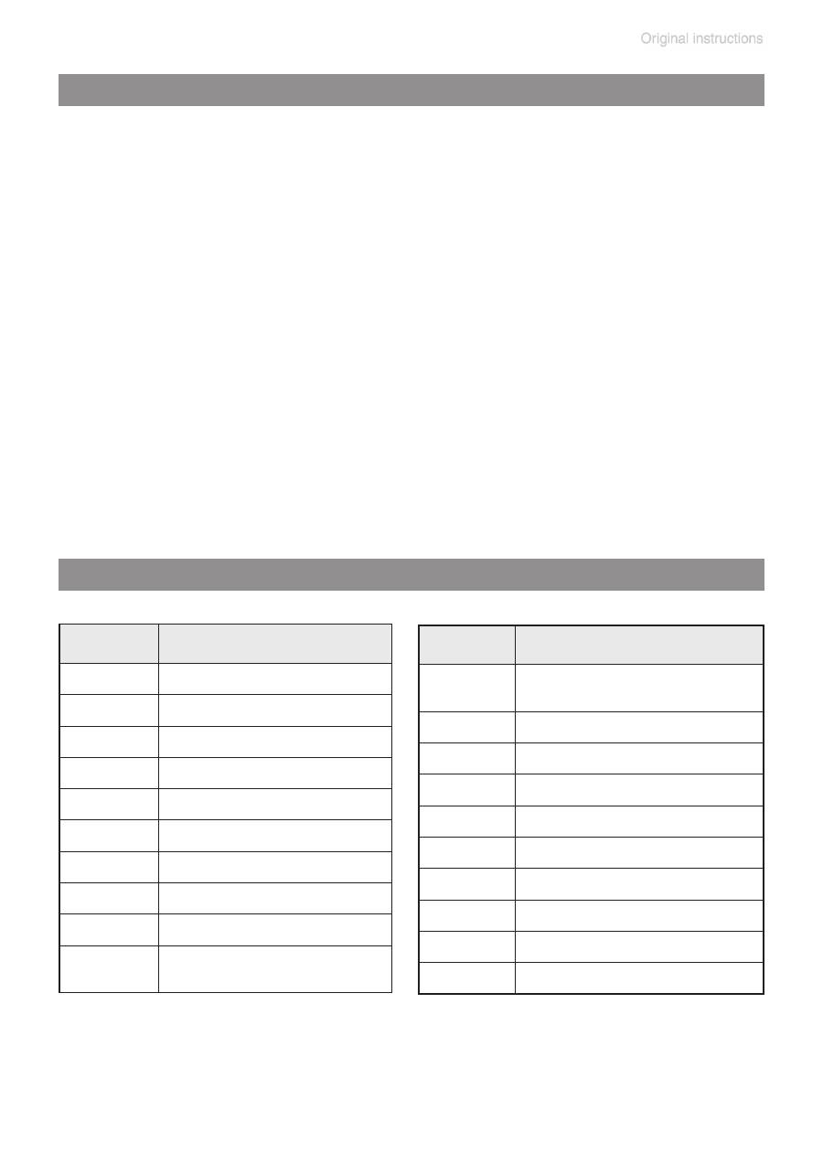
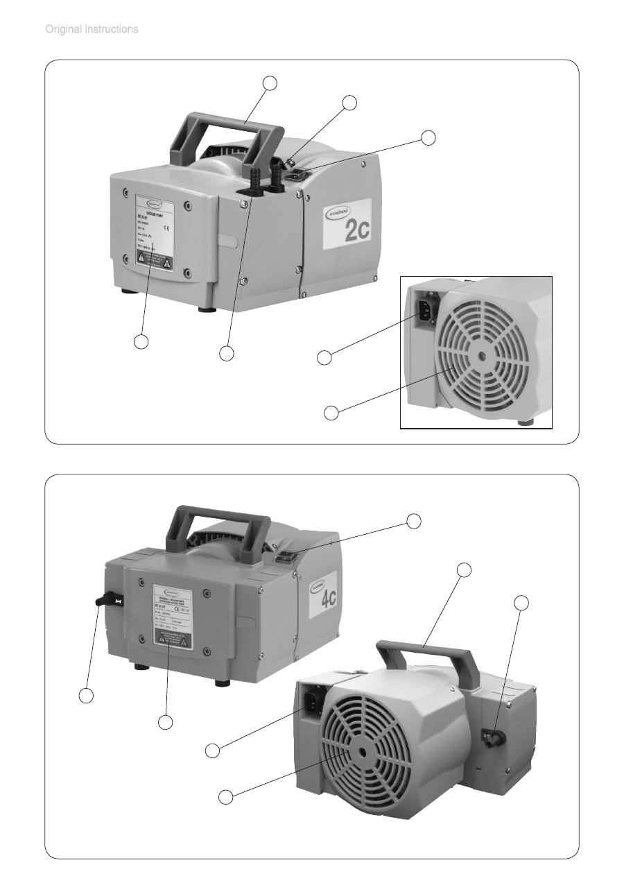
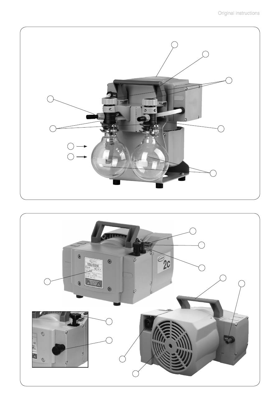
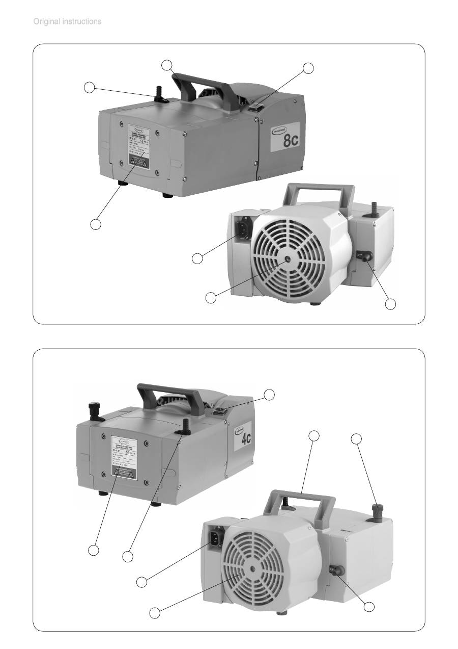
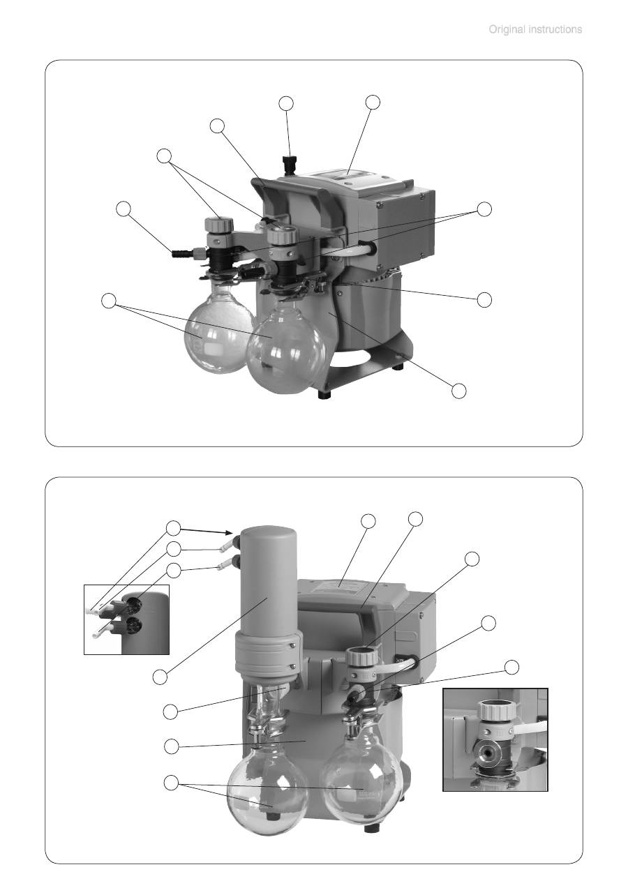
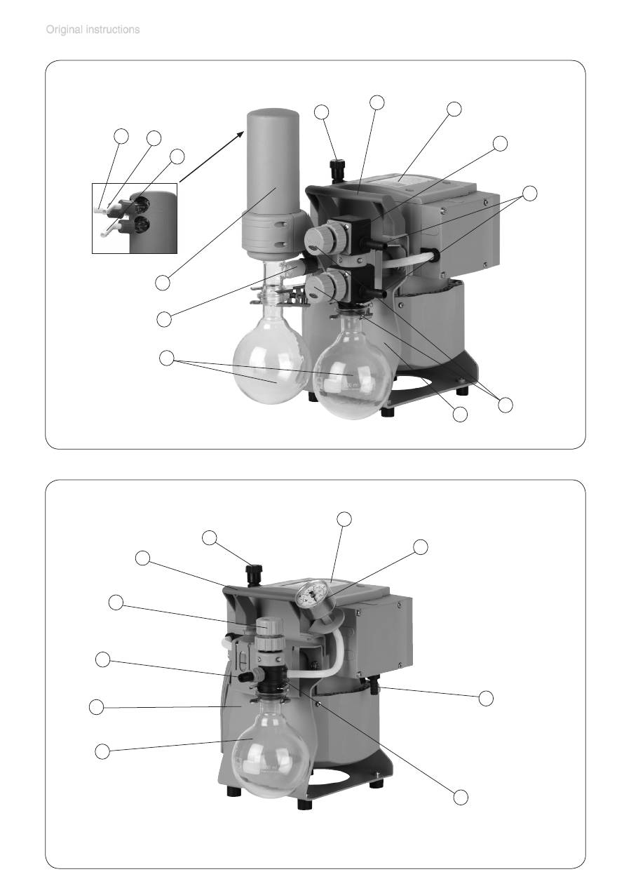
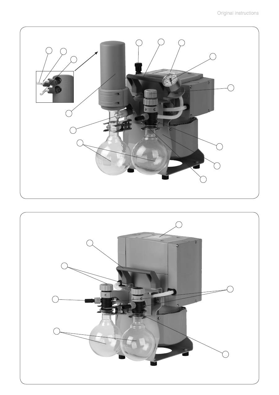
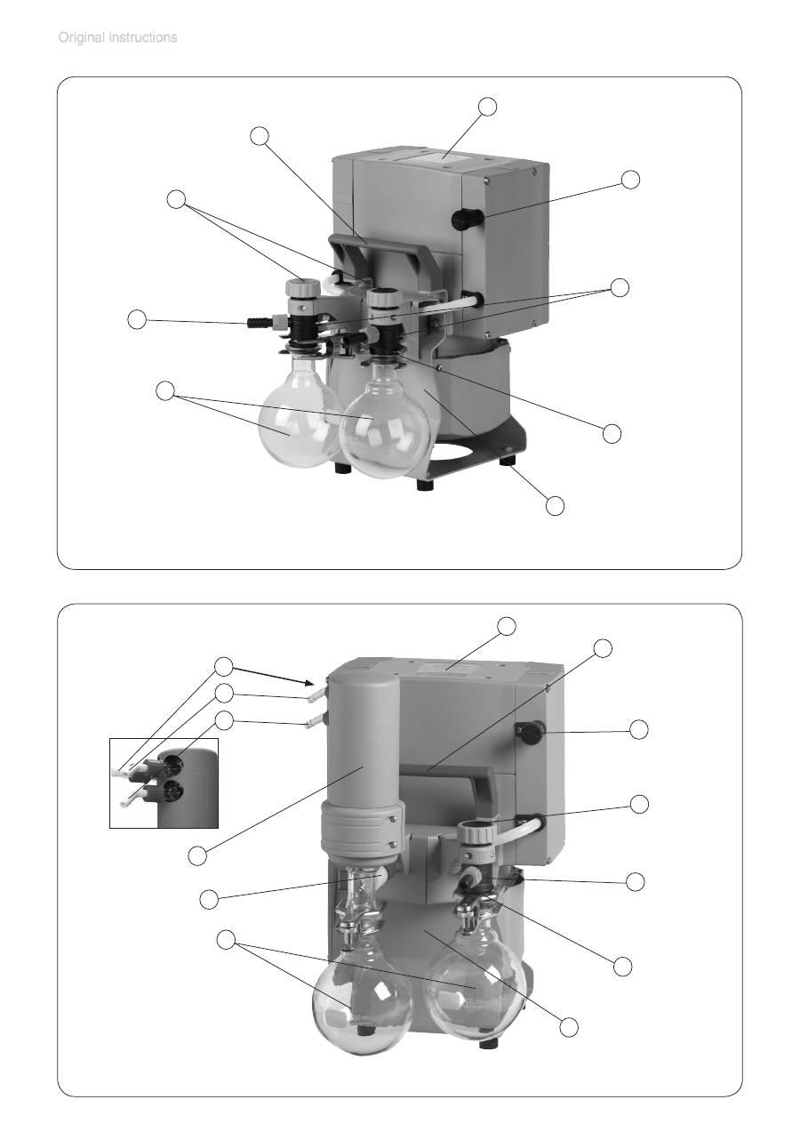
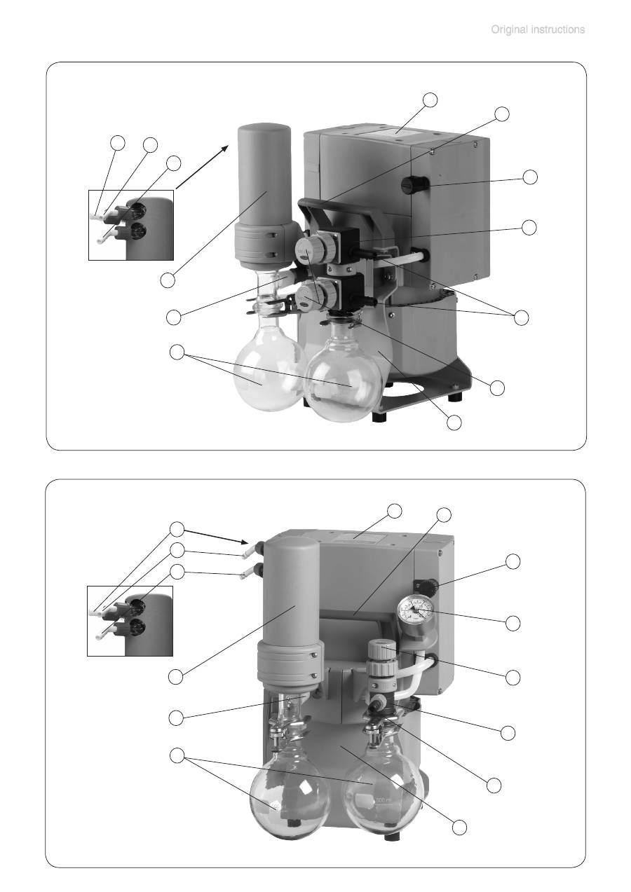
Position
Component
1
Inlet
2
Outlet
3
Gas ballast valve
4
ON/OFF switch
5
Mains connection
6
Handle
7
Pump rating plate
8
Fan
9
Catchpot
10
Exhaust waste vapor
condenser
Position
Component
11
Overpressure safety relief
device
12
Coolant inlet
13
Coolant outlet
14
Flow control diaphragm
15
Manometer
16
Valve block
17
Distribution head
18
Blind plug
19
Voltage selection switch
20
Pump support
We reserve the right for technical modification without prior notice!
Pump parts
Abbreviations
ETFE
: Ethylene/Tetrafluoroethylene
PTFE
: Polytetrafluoroethylene
FFKM
: Perfluoro elastomer
FPM
: Fluoroelastomer
ECTFE
: Ethylene/Chlorotrifluoroethylene
PP
: Polypropylene
PBT
: Polybutylene terephthalate
PET
: Polyethylene terephthalate
PPS
: Polyphenylene sulfide
AK
: separator for condensates, catchpot at inlet or outlet
EK
: exhaust vapor condenser
page 30 of 74
ME 4C NT
1
5
4
7
6
8
2
ME 2C NT
1
5
4
7
6
8
2
page 31 of 74
1
5
3
4
7
6
2
8
1
3
MZ 2C NT KF 16
MZ 2C NT
ME 4C NT + 2 AK
Power connection: see ME 4C NT
6
1
2
7
9
18
17
4
19
page 32 of 74
ME 8C NT
MD 4C NT
1
5
3
4
7
6
2
8
8
5
4
7
6
1
2
page 33 of 74
MZ 2C NT + 2 AK
6
1
2
3
7
9
18
17
Power connection and ON/OFF switch: see MZ 2C NT
20
MZ 2C NT + AK + EK
6
1
2
18
7
10
11
12
13
9
17
alternately:
small flange KF DN 16
at the inlet
20
Power connection
and ON/OFF switch:
see MZ 2C NT
page 34 of 74
MZ 2C NT + AK SYNCHRO + EK
6
1
3
7
10
11
9
14
2
12
13
16
20
Power connection
and ON/OFF switch:
see MZ 2C NT
MZ 2C NT + AK + M + D
6
1
2
3
7
9
15
14
17
20
Power connection and ON/OFF switch: see MZ 2C NT
page 35 of 74
PC 101 NT
6
1
3
7
10
11
9
14
15
2
12
13
17
Power connection
and ON/OFF switch:
see MZ 2C NT
20
6
1
2
7
9
18
17
ME 8C NT + 2 AK
Power connection and ON/OFF switch: see ME 8C NT
page 36 of 74
MD 4C NT + AK + EK
6
1
7
10
11
9
2
12
13
18
17
3
20
Power connection
and ON/OFF switch:
see MD 4C NT
MD 4C NT + 2 AK
6
1
2
3
7
9
18
17
20
Power connection and ON/OFF switch: see MD 4C NT
page 37 of 74
MD 4C NT + AK SYNCHRO + EK
14
1
7
6
9
11
2
12
13
3
10
16
20
Power connection
and ON/OFF switch:
see MD 4C NT
PC 201 NT
6
1
7
10
11
9
14
15
2
12
13
3
17
20
Power connection
and ON/OFF switch:
see MD 4C NT
