HEIDENHAIN IK 5494-2D Installation: IK 5000 QUADRA-CHEK Installation Instructions
IK 5000 QUADRA-CHEK Installation Instructions: HEIDENHAIN IK 5494-2D Installation
English
IK 5000 QUADRA-CHEK
Installation Instructions
Operating Instructions available at www.heidenhain.de
1. How to use these instructions
Contents
The installation instructions contained in this document provide the information
How to use these instructions .................15
necessary to install this product. Operating information can be found in the following
Model information ....................................16
IK 5000 QUADRA-CHEK documents:
Specifications ............................................17
• Video Edge Detection Systems Operating Instructions (ID 735358)
Installation ................................................. 18
• Optical Edge Detection and Crosshair Systems Operating Instructions (ID 735359)
Initial power-up ..........................................20
• Multisensor Systems Operating Instructions (ID 735364)
• Manual 3D Systems Operating Instructions (ID 735365)
• Operating Instructions Addendum (ID 809541-23)
These documents can be downloaded from www.heidenhain.de.
The documents listed below are available to Original Equipment Manufacturer’s (OEM’s)
and can be provided on request.
• OEM System Setup Guide (ID 735363) (for OEM only)
• CNC Setup and PID Loop Tuning (ID 753357) (for OEM only)
• OEM Addendum (ID 1041353-20) (for OEM only)
Contact info@heidenhain.de to request an OEM document.
These instructions are intended for use by personnel qualified to install and maintain the
HEIDENHAIN, IK 5000 QUADRA-CHEK.
A qualified person is someone whose technical education, knowledge and experience,
as well as knowledge of the relevant system of rules qualifies the person to evaluate the
delegated task and recognize possible hazards.
Messages shown in these instructions
The following examples show how safety, property damage and general advice messages
are shown in these instructions. Read and understand these types of messages before
proceeding to prevent personal injury or property damage.
Messages about other safety messages. These supplemental directives do
not address specific hazards, but instead provide information that promotes
awareness and use of specific safety messages.
Warning!
Messages that provide information about the nature of a hazardous situation,
the consequences of not avoiding a hazardous situation, and methods for
avoiding a hazardous situation.
Notice
Messages that provide information primarily about situations that can lead to
property damage, the potential consequences of not avoiding the situations, or
methods for avoiding the situations and general advice messages.
Fonts used in these instructions
Items of special interest or concepts that are emphasized to the user are shown in bold
type.
15
IK 5000 QUADRA-CHEK
Installation Instructions
Operating Instructions available at www.heidenhain.de
2. Model information
This guide covers multiple products. Whenever possible the product name shown on
the cover page is used. When a feature pertains to a specific product variant the specific
product name or the product name and the ID are shown.
This guide covers specifications, mounting and installation for the following models:
Connector IK 529x IK 529x IK 539x IK 539x IK 549x IK 549x IK 549x IK 559x
Axes XYZ
A • • • • • • • •
Axes Q
H Optional Optional Optional Optional - Optional Optional Optional
Optical edge
P, R - - • - • - - -
detector
Light control
K - - - Optional - Optional Optional •
Zoom control
N - - - Optional - Optional Optional Optional
Touch probe
M - • - • - - • TP200
CNC XYZ
B - - - - • • • •
CNC Q
J - - - - - Optional Optional Optional
ID
678414-xx 678415-xx 678416-xx 678417-xx,
678419-xx 678420-xx 678421-xx 678422-xx
678418-xx
Index
- - - - - - - -
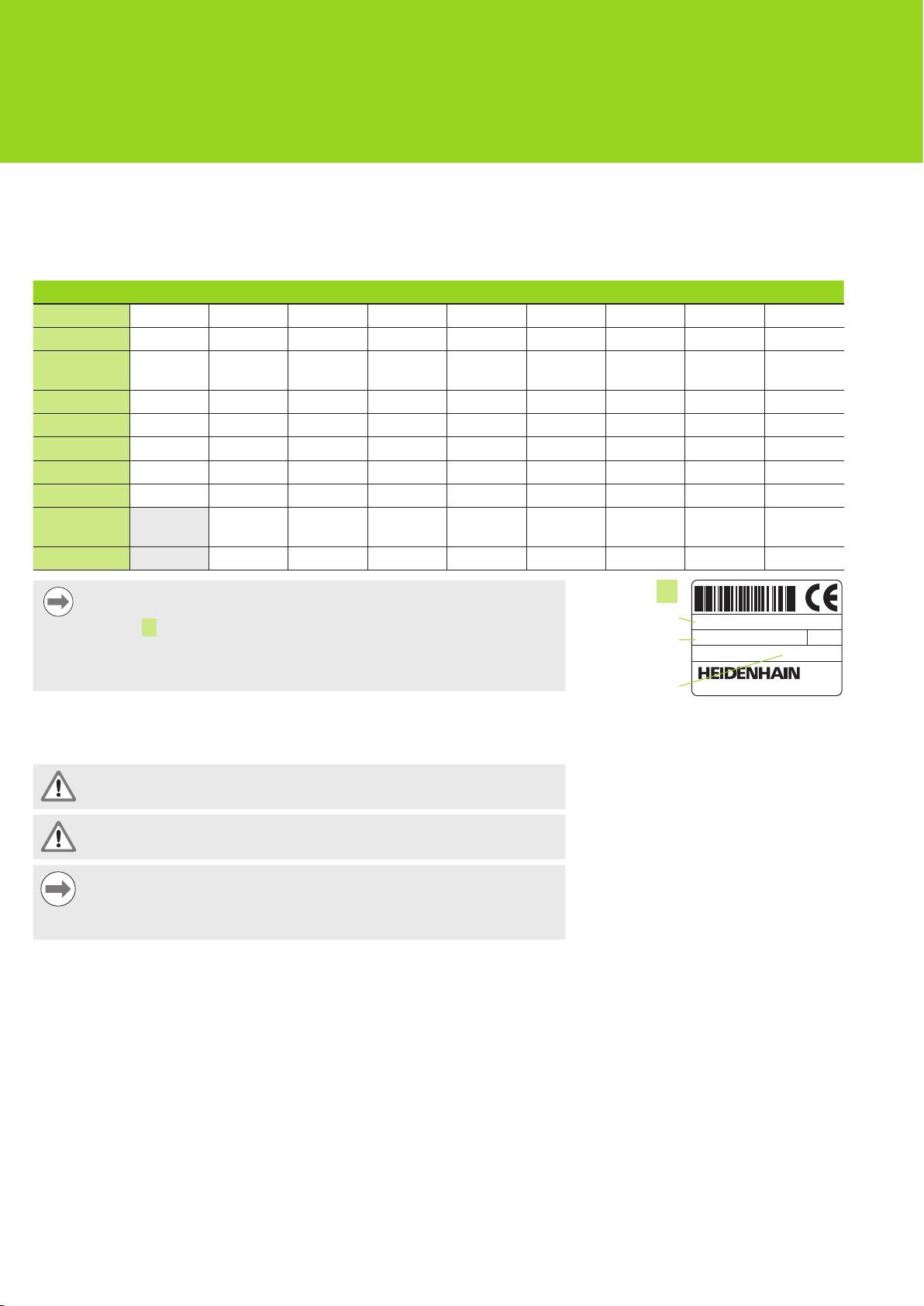
Notice
L
Verify that these Installation Instructions are valid by matching the Index on
Product name
IK xxxx QUADRA-CHEK
the label L with the Index listed at www.heidenhain.de. If these instructions
ID
ID 123456-xx xx
are not valid, download the applicable Installation Instructions from
SN 12 345 678 x
www.heidenhain.de.
An index may not be present on all products.
Index
ID label, Located on back of card
Safety
The following messages provide safety information for preventing personal injury and
product damage:
Read and understand these instructions before use to avoid the possibility of
personal injury or death.
The protection provided by the equipment may be impaired if used in a manner
not specified. Do not use this product in any way other than its intended use.
Notice
For safety, operation and handling of the product, keep this document for
future reference. This document must be kept within reaching distance of the
product.
16

IK 5000 QUADRA-CHEK
Installation Instructions
Operating Instructions available at www.heidenhain.de
3. Specifications
®
The IK 5000 QUADRA-CHEK is a family of Windows
PC based products for conducting
precision dimensional measurements of 2D and 3D parts on comparators, coordinate
measuring systems and measuring microscopes. Systems are available in versions for 3
or 4 axes and support manual part positioning and measurement under user control, or
CNC part positioning and automated measurement under program control. This product
is designed for indoor use only. The IK 5000 QUADRA-CHEK components shall only
be installed as described in these instructions. Installation and maintenance are to be
performed by qualified personnel only.
Specifications
Power input
PCI connector to PC
G: DC 5 V (± 5 %), DC 12 V (± 5 %), DC -12 V (± 5 %)
IK 5000 card power connector
E : DC 5 V (± 5 %), DC 12 V (± 5 %)
Input frequency XYZ
A
, Q
H
:
» 1 V
PP
differential: max. 3.6 MHz
« TTL differential: max. 5.1 MHz
« TTL single-ended: max. 2.2 MHz
Power consumption
IK 5000 card +12 V: 3600 mW
-12 V: 1200 mW
+5 V: 6250 mW
+3.3 V: 1650 mW
total: 12700 mW
XYZ
A
, Q
H
: max. 375 mW
XYZ
B
: max. 650 mW
Q
J
: max. 500 mW
Zoom
N
: rated 600 mW
Light
K
: rated 800 mW
Specification: PCI local bus Spec. Rev. 2.2
Connector: PCI V / 32-bit connecting element
PCI component: PCI 9030 from PLX, target interface (slave)
Identifier in component PCI 9030
Vendor ID: 0x10B5
Device ID: 0x2065
Environmental conditions
Operating temperature: 0 °C ... 55 °C
Storage temperature: -30 °C ... 70 °C
Relative humidity: 80 %
ID 678417-xx
ID 678418-xx
ID 678414-xx
ID 678416-xx
ID 678420-xx
ID 678415-xx
ID 678419-xx
ID 678421-xx ID 678422-xx
Mass: 122 g 184 g 150 g 190 g
17
IK 5000 QUADRA-CHEK
Installation Instructions
Operating Instructions available at www.heidenhain.de
4. Installation
Read and understand the OEM system manufacturer Operating Instruction and
the PC manufacturer Operating Instruction before beginning the installation to
avoid the possibility of personal injury or death.
The safety of any system incorporating the use of this product is the
responsibility of the assembler or installer of the system.
Notice
Do not engage, or disengage any connections while the unit is under power.
Damage to internal components may result.
Interfaces
Interface connections Interface connections Interface connections
X,Y and Z Encoder and foot switch
IK 5000 card PCI connector to PC
Camera zoom control output
A
G
N
inputs
motherboard
X,Y and Z axis CNC control outputs
Q axis encoder input
Comparator light source input for
B
H
P
optical edge detection
IK 5000 card connection to Flyout
DIP switches for interpolation
Comparator screen sensor input for
C
I
R
connectors
H
and
J
settings
optical edge detection
IK 5000 card connection to Flyout
Q axis CNC control output
Optical daughter board optical cables
D
J
T
connector
K
through connectors
P
and
R
to
the comparator light source and
screen sensor
IK 5000 card power connector
Video light outputs
TP200 daughter board connection to
E
K
V
flyout connector
M
IK 5000 card connection to flyout
Touch probe input
RS-232 PC motherboard connector
F
M
W
connector
N
Minimum system requirements
Component w/o 3D profiling w/ 3D profiling
PC
2.66 GHz dual-core Pentium 2.8 GHz quad-core Pentium
Operating System
Windows XP
(OS)
Windows Vista 32-bit
Windows 7 32-bit, 64-bit
Windows 8 32-bit, 64-bit
RAM
1GB 2GB
Available Hard Disk
500MB 1GB
PCI
1 PCI slot and 1 to 3 additional empty slots (depending on the
version)
Video Display Unit
1024 x 768 resolution
Windows users rights
Administrator
18
IK 5000 QUADRA-CHEK
Installation Instructions
Operating Instructions available at www.heidenhain.de
PC card and flyout installation
Warning! Risk of electrical shock
A risk of electrical shock exists if the OEM system or PC power is on.
To avoid the hazard, verify that the OEM system and PC power is off before
opening the PC enclosure..
Warning! Risk of electrical shock
A risk of electrical shock exists if the OEM system and PC are not properly
grounded.
To avoid the hazard, always use a 3-conductor (grounded) power cord and
ensure the ground is properly wired to the building installation.
Notice
This product and the PC contain components that can be damaged by
electrostatic discharge (ESD). Observe precautions for handling ESD
sensitive devices and never touch connector pins unless properly grounded.
The installation of the IK 5000 PC card and associated flyouts requires only a screwdriver
and personal antistatic protection.
Prepare the PC
Shut down the PC
Disconnect the power cord from the PC
Open the PC enclosure. Refer to the PC manufacturer’s Operating Instructions for
enclosure access instructions.
Remove any covers or panels to gain access to the motherboard PCI expansion slots
Remove flyout blanks
Remove flyout blanks from the PC to accommodate the flyouts required for the specific
IK 5000 QUADRA-CHEK system
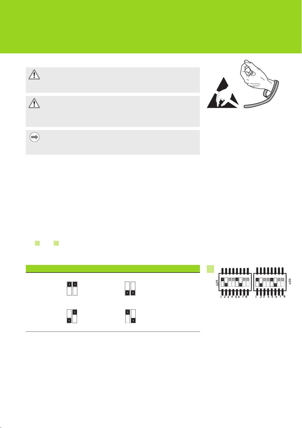
Set interpolation
XYZ
A and Q H « 1 V
PP
encoder signals are interpolated. Interpolation can be
changed by the DIP switch settings on the IK 5000 QUADRA-CHEK card.
Using the point of a small screwdriver, change dip switch settings to the desired
interpolation. Refer to the Interpolation settings table below.
Interpolation settings
Possible settings for each switch pair (1-2, 5-6) using switch pair 1-2 as an example pair:
X20 Interpolation
19
X25 Interpolation
1 2
Observe ESD handling precautions
I
X100 Interpolation
1 2
1 2
X50 Interpolation
(Factory default)
1 2
Q Z
Y X
DIP switches

IK 5000 QUADRA-CHEK
Installation Instructions
Operating Instructions available at www.heidenhain.de
Install the IK 5000 card
Do no touch the PCI edge connector
G while installing the IK 5000 card.
Carefully plug the IK 5000 card into a PCI slot location. Limit card handling to the card
edges as much as possible and secure the card with a bracket screw.
Install flyouts
Install the flyouts into the appropriate locations and secure with bracket screws
Connect flyout cables to the card
Plug the internal flyout cables for the appropriate card connectors into connectors
C , D , F and V with the cable connector flanges facing down. Refer to the Card,
Flyout and Connector Configuration diagrams on earlier pages for the correct and
required cable connections.
Connect the PC internal power supply to the card
Plug the 4-pin power cable from the PC internal power supply into the power connector
E at the top of the card making sure that the PC power supply connector’s retaining
clip is facing the card
Close the PC enclosure
Confirm that all cards, cable connections and flyouts are securely fastened and then
replace the PC covers or panels
Connect all other system hardware
Refer to the Card, Flyout and Connector configuration diagram for the specific system
and connect all other system hardware to the IK 5000 QUADRA-CHEK card, flyouts and
PC connectors.
Connecting a PC power cord
To connect a PC power cord:
Verify that the PC power switch is in the off position
Verify that the PC power cord is not plugged into the main power supply
Insert the female end of the PC power cord into the PC power connector on the rear of
the PC
5. Initial power-up
Refer to the PC manufacturer’s Operating Instructions for power-up instructions.
20
Оглавление
- IK 5000 QUADRA-CHEK Product overview
- IK 5000 QUADRA-CHEK Card, flyout and connector configurations
- IK 5000 QUADRA-CHEK Installationsanleitung
- IK 5000 QUADRA-CHEK Installationsanleitung
- IK 5000 QUADRA-CHEK Installation Instructions
- IK 5000 QUADRA-CHEK Guide d'installation
- IK 5000 QUADRA-CHEK Istruzioni di installazione
- IK 5000 QUADRA-CHEK Instrucciones de instalación
- IK 5000 QUADRA-CHEK Installationsanvisning
- IK 5000 QUADRA-CHEK Installatie-instructies
- IK 5000 QUADRA-CHEK Pokyny k instalaci
- IK 5000 QUADRA-CHEK Instruções de Instalação
- IK 5000 QUADRA-CHEK Instrukcja instalacji
- IK 5000 QUADRA-CHEK Инструкция по установке
- IK 5000 QUADRA-CHEK Kurulum Talimatları
- IK5000QUADRA-CHEK 設置説明書
- IK5000QUADRA-CHEK 安装说明
- IK 5000 QUADRA-CHEK Dimensions
- IK 5000 QUADRA-CHEK Connector pin assignments
