Eneo GXB-1710M/IR: DE EN FR PL RU
DE EN FR PL RU: Eneo GXB-1710M/IR
15
DE
EN
FR
PL
RU
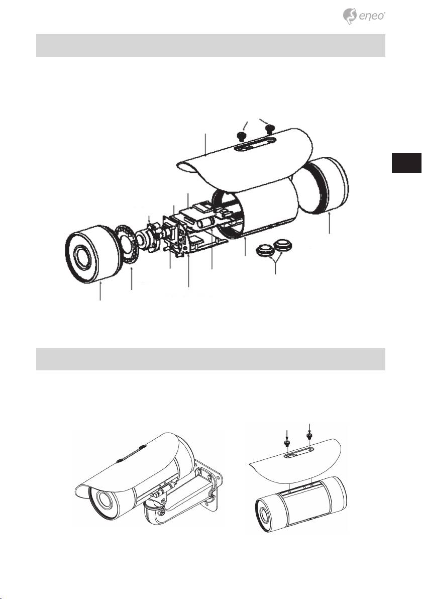
2. The Component Parts (internal view)
The picture here shows you the internal component items making up the
product.
Screws
Sun shield
SD PCB
Fan
Lens
Rear case
Middle case
Sensor PCB
Power PCB
Waterproof rubber
PCB plate
IR PCB
Front case
3. Camera with Bracket (external view)
The picture here shows the camera‘s exterior, with the bracket screwed in
and fixed to it. The bracket enables you to easily mount the camera on a
wall, turned at the angle you want.
NOTE: Use the 2 screws to screw the sun shield (above) into the
2 extreme holes indicated in the bullet camera (below) to get an
unobstructed viewing angle.
Please don’t use the middle hole in the camera, as that will block
the view.
Installation
Please follow the steps given below to install, configure and set the
IP Camera.
1. Check the IP class of your PC
Step 1: From the Start menu, point to Settings, and then click Control
Panel.
Step 2: When Control Panel appears, double-click the Network Connec-
tions icon. The Network Connections dialog box appears.
Step 3: Click the Protocols tab in the Network Connections dialog box.
Step 4: When the Local Area Connection Properties dialog box shows
up, choose Internet Protocol (TCP/IP) and click Properties.
Step 5: In the Internet Protocol (TCP/IP) Properties dialog box, choose
Use the following IP Address to indicate that you do not wish to
use DHCP, and assign IP Address 192.168.1.200 with Subnet
mask 255.255.255.0. Click OK when you finish it.
Step 6: Choose Close to finish the modification.
2. Install UPnP Packets of your PC
As described before, Microsoft Windows XP® doesn’t start the UPnP
service by default; however, we have to install some packets before we
initialize it. The following steps will help you to install them.
Step 1: From the Start menu, point to Set Program Access and Default,
and then click it.
Step 2: When the Add or Remove Programs dialog box appears, click the
Add/Remove Windows Components button.
16

17
DE
EN
FR
PL
RU
Step 3: Check the Network Services in the Windows Component Wizard
dialog box, and then click Details….
Step 4: Check UPnP User Interface, and choose OK.
Step 5: When the original Network Component Wizard dialog box returns,
click Next.
Step 6: After about one minute the UPnP installation will be done, and
choose Finish to close it.
3. Turn on Services of your PC
After installation, we should turn on the relative services to start the UPnP
protocol. The following procedures will teach you how to do it.
Step 1: From the Start menu, point to Settings, and then click Control
Panel.
Step 2: When Control Panel appears, double-click the Administrative
Tools icon. The Administrative Tools dialog box appears.
Step 3: Click the Services icon in the Administrative Tools dialog box.
Step 4: When the Services dialog box shows up, double click the SSDP
Discovery Service icon.
Step 5: Choose Automatic in the Startup type, and click OK to start it.
Step 6: When the Services dialog box appears again, double click the
Universal Plug and Play Device Host icon.
Step 7: Choose Automatic in the Startup type, press the Start button,
and click OK to start it.
Step 8: Restart your system.
4. Set the static IP address in the IP Camera
Step 1: Plug in its power connection.
Step 2: Plug the USB connector in your PC and in the USB socket in the
rear of the lens.
Step 3: A window pops up asking if you want to „Run the program“,
„Open folder to view files“, or „Take no action“. Choose „Run the
program“ and click „OK“, and the „USB configuration“ window will
pop up.
Step 4: Set the Network setting and type in the IP address you desire.
Before you change the IP address, you should note the factory
default Static IP address ( 192.168.1.10 ).
Step 5: After changing the IP address, click the „Apply“ button in the
„USB Configuration” window.

Step 6: A message pops up asking you to affirm the action as „OK“.
Step 7: Click „OK“, and remove the USB connection from your PC.
Step 8: Click „Exit“ at the bottom of the „USB Configuration” window to
close the window. Or, choose the „Launch“ button to see the local
camera images directly.
Step 9: Before clicking „Launch“, check your PC‘s IP address and use the
Network connector ( RJ-45 ) to link up with your camera.
Step 10: If you can see the images, it means the IP setting is complete.
5. Scan IP Camera through “My Network Place”
Step 1: After your installation and starting services, the UPnP protocol will
take effect. You can scan all IP Cameras in My Network Place.
Step 2: Just double click the IP Camera icon, and the video live stream
will pop up automatically without assigning any IP address in
Microsoft Internet Explorer.
6. Change the IP Camera‘s control and operational settings
Step 1: Type in the IP address in the IE Browser. You will now see the IP
camera‘ images.
Step 2: Use the buttons below the images to enter any other operational
settings pages.
Step 3: When you change any setting, please don‘t forget to click the
„Submit” button in each page.
NOTE: Enable DHCP Function: This function can only work if the LAN,
which the unit is connected to, has a DHCP server. If the DHCP
server is working, the IP Camera will obtain an IP address auto-
matically from the DHCP server.
NOTE: When only one unit of the IP Camera is connected to a
computer or LAN, you can freely assign an IP address for the
IP Camera. For example, there is a range of IP Camera IP
addresses from 192.168.1.1 to 192.168.1.255. You can pick one
for use from the range of the IP. It’s not necessary to set MASK
and GATEWAY; leave the settings as default. When an IP
Camera is connected to a WAN, you must acquire a unique,
permanent IP address and correctly configure the MASK and
GATEWAY settings according to your network architecture.
If you have any questions regarding those settings, please
consult a qualified MIS professional or your ISP.
18
19
DE
EN
FR
PL
RU
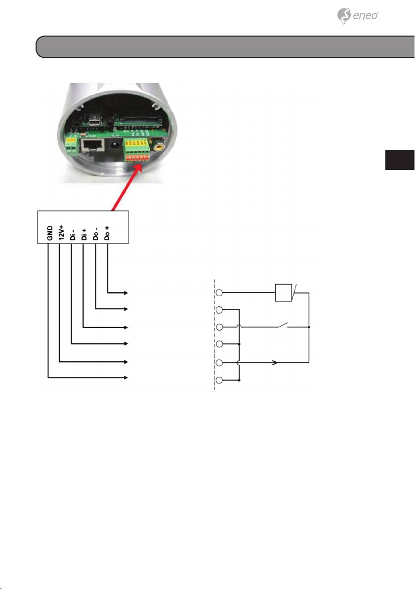
Alarm Wiring Diagram
+12V
Digital output +
ALARM
Digital output -
Digital input +
Reed switch
Digital input -
+12V
DC output
+12V, 100mA
GND
Hardware Installation
1. Plug in the power connection to the IP camera.
2. Plug in the IP camera cable.
3. Confirm the correct network connection status (PC/HUB/ IP camera).
4. In the PC IE Browser, key in the camera’s IP online to link up to the live
first page.
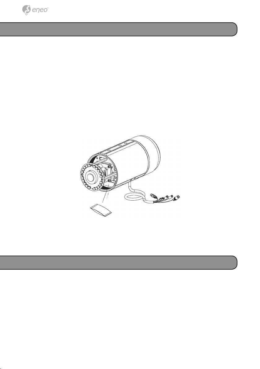
NOTE: The user can replace the desiccant pack depending on how often
the camera interior has been opened to the environment. Stick
and fix a desiccant pack to the inner side of the camera with a
two-side adhesive tape, then reattach the cover of the camera.
Further information
The Full Manual is available from the eneo web site at
www.eneo-security.com or from the CD supplied with this product.
20
Оглавление
- DE EN FR PL RU
- DE EN FR PL RU
- DE EN FR PL RU
- DE EN FR PL RU
- DE EN FR PL RU
