Dell Latitude X300: инструкция
Раздел: Компьютерная техника, комплектующие, аксессуары
Тип: Ноутбук
Инструкция к Ноутбуку Dell Latitude X300
Оглавление
- Dell™ Latitude™ X300 User's Guide

Dell™ Latitude™ X300 User's Guide
Click the links to the left for information on the features and operation of your computer. For information on other documentation included with your computer,
see "
Finding Information
."
Notes, Notices, and Cautions
Abbreviations and Acronyms
For a complete list of abbreviations and acronyms, see the
Glossary
.
____________________
Information in this document is subject to change without notice.
© 2003 Dell Computer Corporation. All rights reserved.
Reproduction in any manner whatsoever without the written permission of Dell Computer Corporation
is strictly forbidden.
Trademarks used in this text:
Dell
, the
DELL
logo,
Latitude
,
Dell Precision
,
OptiPlex
,
Inspiron
,
Dimension
,
Dell TravelLite
, and
DellNet
are trademarks of Dell Computer Corporation;
Intel
,
Pentium
, and
Intel
SpeedStep
are registered trademarks and
Centrino
is a trademark of Intel Corporation;
Microsoft
, and
Windows
are registered trademarks of Microsoft
Corporation;
Bluetooth
is a trademark owned by Bluetooth SIG, Inc. and is used by Dell Computer Corporation under license;
ENERGY STAR
is a registered trademark of the U.S.
Environmental Protection Agency. As an ENERGY STAR Partner, Dell Computer Corporation has determined that this product meets the ENERGY STAR guidelines for energy
efficiency.
Other trademarks and trade names may be used in this document to refer to either the entities claiming the marks and names or their products. Dell Computer Corporation
disclaims any proprietary interest in trademarks and trade names other than its own.
Model PP04S
May 2003
P/N D0979 Rev. A00
CAUTION:
Follow the safety instructions in the
System Information Guide
to help protect your computer from damage and ensure your own
personal safety.
NOTE:
A NOTE indicates important information that helps you make better use of your computer.
NOTICE:
A NOTICE indicates either potential damage to hardware or loss of data and tells you how to avoid the problem.
CAUTION:
A CAUTION indicates a potential for property damage, personal injury, or death.
About Your Computer
Front View
Left Side View
Right Side View
Back View
Bottom View
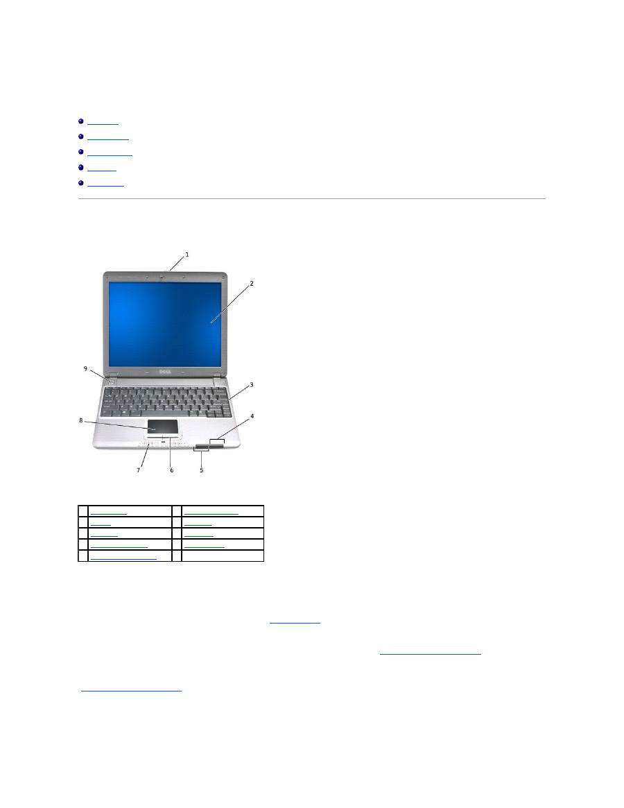
Front View
display latch
—
Keeps the display closed.
display
—
For more information on using your color display, see "
Using the Display
."
Press this button to launch a frequently used program, such as your default Internet browser.
The button is initially programmed to launch your default Internet browser. For more information, see "
Using the Keyboard and Touchpad
."
keyboard
—
The keyboard includes a numeric keypad as well as the Microsoft
®
Windows
®
logo key. For information on supported keyboard shortcuts, see
"
Using the Keyboard and Touchpad
."
device status lights
1
display latch
6
touch pad buttons
(2)
2
display
7
speakers
(2)
3
keyboard
8
touch pad
4
device status lights
9
power button
5
keyboard status lights
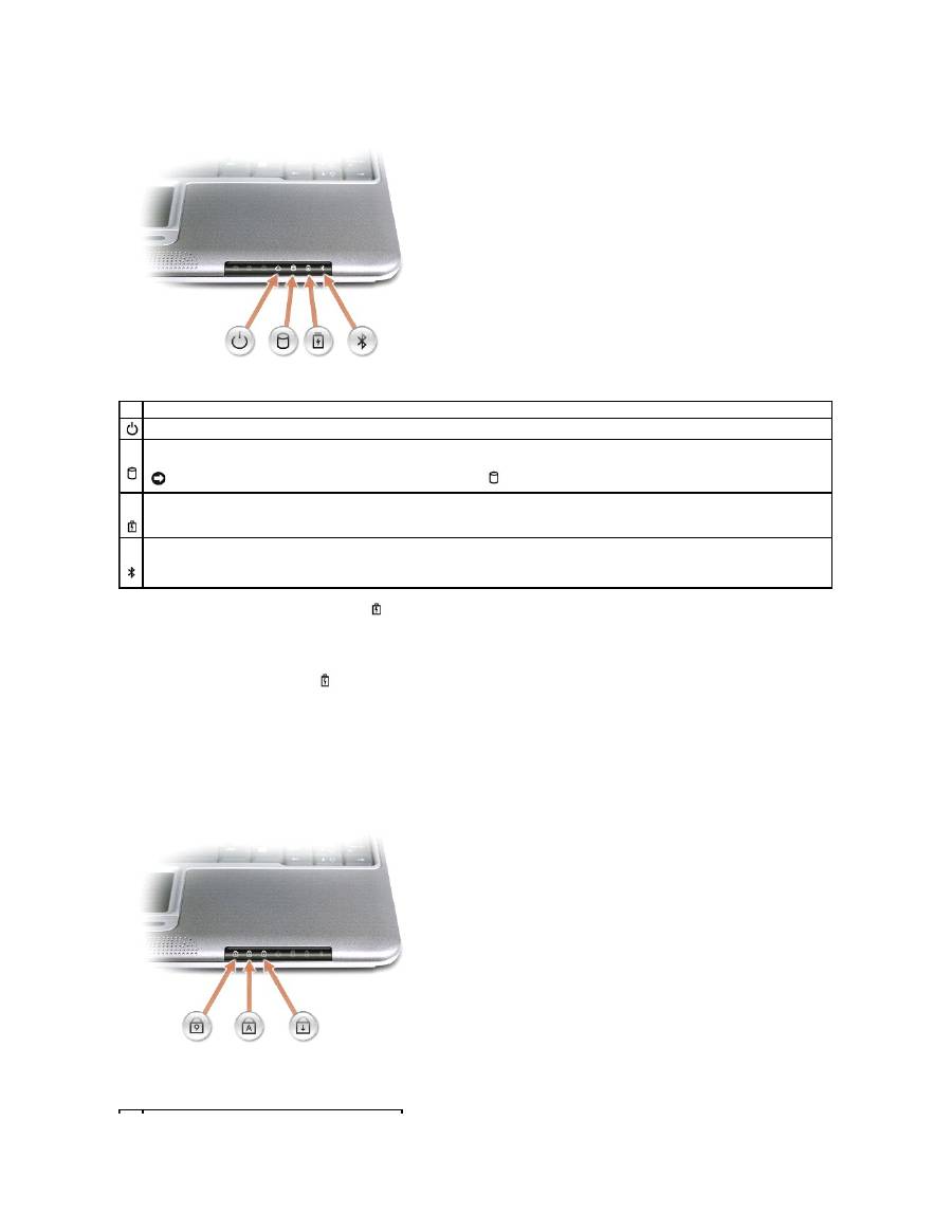
If the computer is connected to an electrical outlet, the
light operates as follows:
¡
Solid green: The battery is charging.
¡
Flashing green: The battery is almost fully charged.
¡
Off: The battery is fully charged.
If the computer is running on a battery, the
light operates as follows:
¡
Off: The battery is adequately charged (or the computer is turned off).
¡
Flashing orange: The battery charge is low.
¡
Solid orange: The battery charge is critically low.
keyboard status lights
The green lights located on the keyboard indicate the following:
Device Status Lights
Turns on when you turn on the computer or blinks steadily when the computer is in standby mode..
Turns on when the computer reads or writes data.
NOTICE:
To avoid loss of data, never turn off the computer while the
light is flashing.
Indicates battery charge status.
Turns on only if the Bluetooth™ module is already installed and the wireless antenna is enabled. To enable or disable the antenna, press <Fn><F2>.
NOTE:
The wireless features on your computer, including Bluetooth and Mini PCI Wi-Fi, are optional. For more information, see the documentation that
came with your wireless technology.
touch pad buttons
—
Correspond to the left and right buttons on a standard mouse.
speakers
—
The computer speakers are located inside the front center edge of the computer. Press the volume control keyboard shortcuts to adjust the
volume of the integrated speakers. For more information, see "
Using the Keyboard and Touchpad
."
touch pad
—
Use the touch pad and touch pad buttons as you would use a mouse. See "
Using the Keyboard and Touchpad
" for more information.
power button
—
Press the power button to turn on the computer or to enter standby mode.
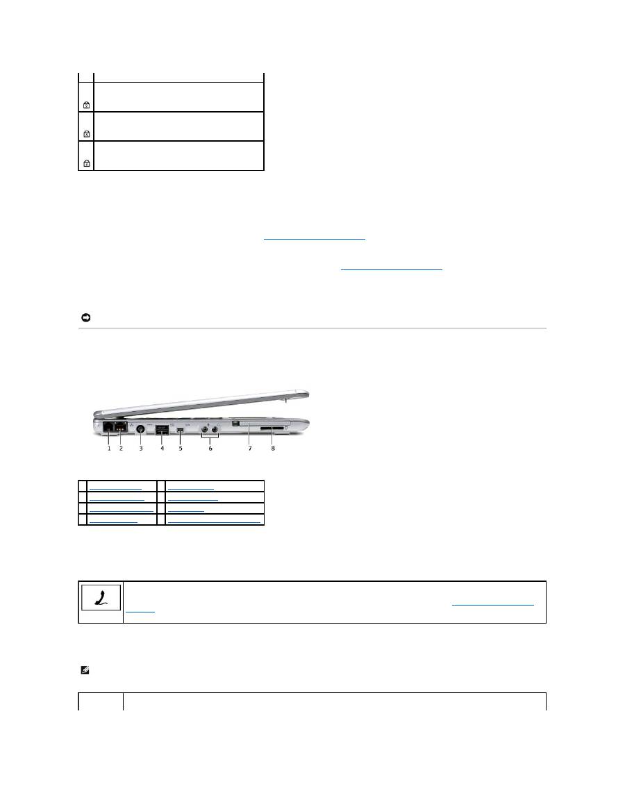
Left Side View
modem connector
network connector
Keyboard Status Lights
Turns on when the numeric keypad is enabled.
Turns on when the uppercase letter function is enabled.
Turns on when the scroll lock function is enabled.
NOTICE:
Turn off your computer by performing a Windows shutdown rather than by pressing the power button. Otherwise, you may lose data.
1
modem connector
5
1394 connector
2
network connector
6
audio connectors
3
AC adapter connector
7
PC Card slot
4
D/Bay connector
8
Secure Digital memory card slot
Connects the telephone line.
For information on using the modem, see the online modem documentation supplied with your computer. See "
Finding Information for Your
Computer
."
NOTE:
The network connector is slightly larger than the modem connector. Do not plug a telephone line into the network connector.
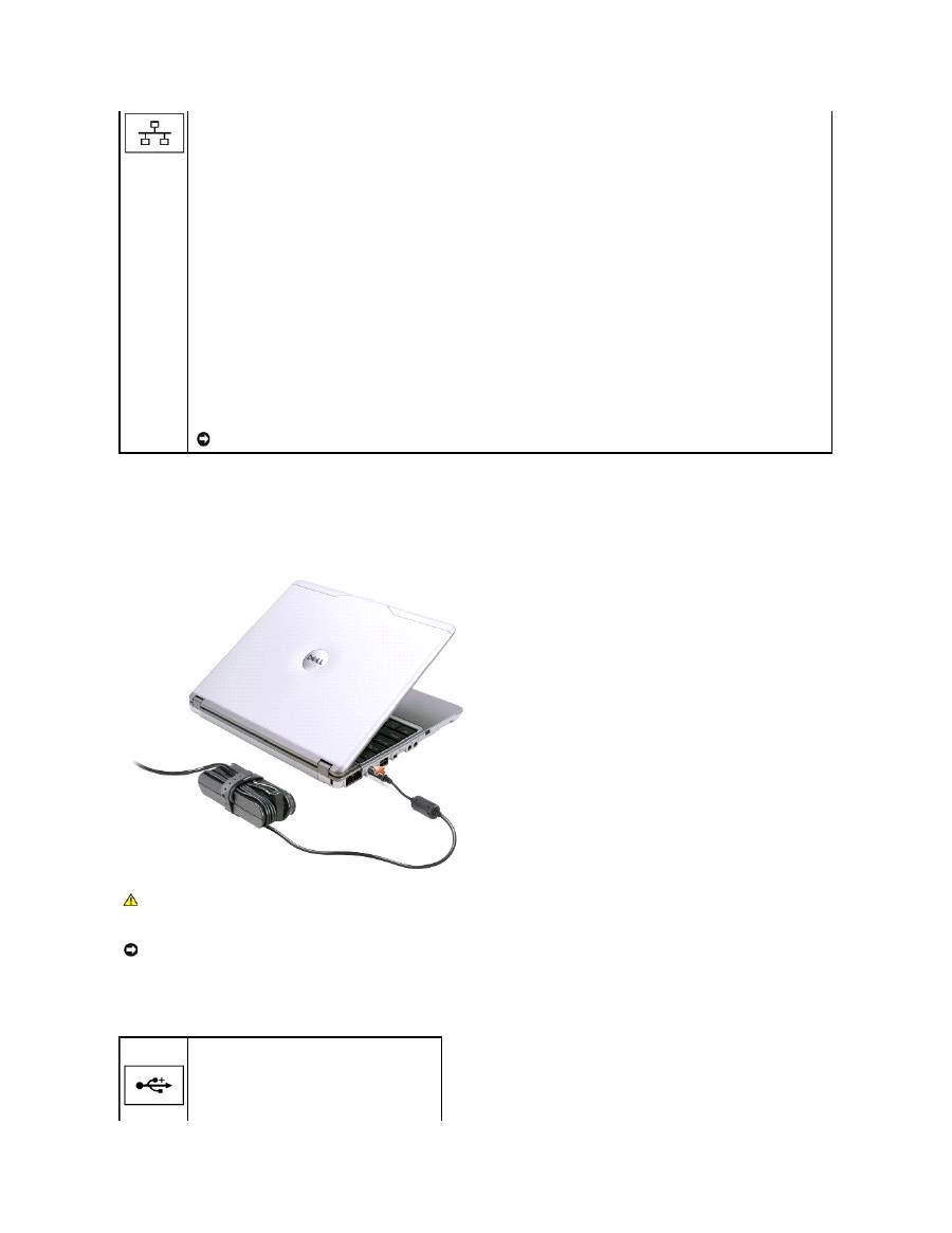
AC adapter connector
—
Attach an AC adapter to the computer and to AC power to convert AC power to the DC power required by the computer. You can
connect the AC adapter with your computer either turned on or off.
The power cable manager can be removed from the AC adapter. For details, see the label that came with your AC adapter.
D/Bay connector
RJ-45 network connector
—
Connects the the computer to a network.
The network connector has status lights on both sides.
If the light on the right is off, the media base is not detecting a network connection. Try replacing the network cable. The light on the right
blinks yellow when the network is active.
The light on the left indicates the link speed:
Solid Green
—
Connection speed is 10 Mbps.
Amber
—
Connection speed is 100 Mbps.
Yellow
—
Connection speed is 1 Gbps.
For information on using the network adapter, see the documentation that came with your computer.
NOTICE:
Do not plug a telephone cable into the network connector.
CAUTION:
If you are using a multiple-outlet power strip, use caution when plugging the AC adapter's power cable into the power strip. Some
power strips may allow you to insert the plug incorrectly. Incorrect insertion of the power plug could result in permanent damage to your
computer, as well as risk of electric shock and/or fire. Ensure that the ground prong of the power plug is inserted into the mating ground contact
of the power strip.
NOTICE:
When you disconnect the AC adapter from the computer, hold the adapter cable connector, not the cable itself, and pull firmly but gently to
avoid damaging the cable.
Connects powered USB devices such as a Dell™ D/Bay.
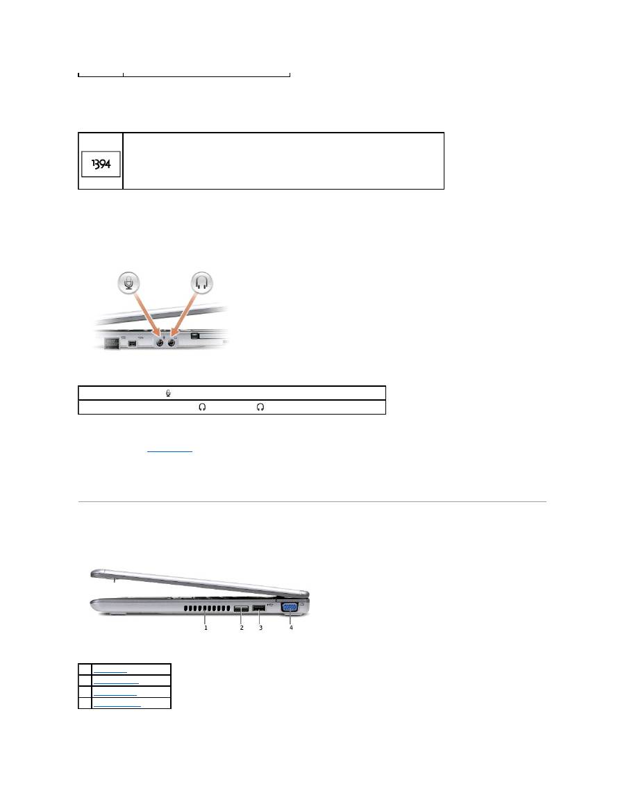
1394 connector
audio connectors
PC Card slot
—
The PC Card slot supports one PC Card, such as a modem or network adapter. The computer ships with a plastic blank installed in the slot. For
more information, see "
Using PC Cards
."
Secure Digital memory card slot
—
The Secure Digital memory card slot supports one Secure Digital memory card. Use Secure Digital memory cards to save or
back up data.
Right Side View
Use to attach devices supporting IEEE 1394 high-speed transfer rates, such as some digital video cameras.
Attach a microphone to the
connector.
Attach headphones or speakers to the
connector. The
connector is a stereo output connector.
1
air exhaust
2
infrared sensor
3
USB connector
4
video connector

infrared sensor
—
Lets you transfer files from your computer to another IrDA-compatible device without using cable connections.
When you receive your computer, the sensor is disabled. You can use the system setup program to enable the sensor. For information on transferring data,
see Windows
Help,
the Windows Help and Support Center, or the documentation that came with your IrDA-compatible device.
air exhaust
—
The computer uses an internal fan to create airflow through the vents, which prevents the computer from overheating.
USB connector
video connector
Back View
security cable slot
—
Lets you attach a commercially available antitheft device to the computer. Instructions for installing antitheft devices are usually included
with the device.
NOTE:
The computer turns on the fans when the computer gets hot. The fans may make noise, which is normal and does not indicate a problem with
the fans or the computer.
CAUTION:
Do not block, push objects into, or allow dust to accumulate in the air vents. Doing so can damage the computer or cause a fire.
Connects USB devices, such as a mouse, keyboard, or printer.
Connects an external monitor or projector. See "
Using the Display
."
1
security cable slot
NOTICE:
Before you buy an antitheft device, ensure that it will work with the security cable slot.
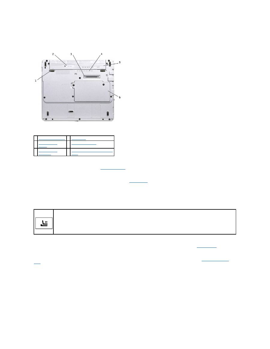
Bottom View
battery latch release
—
Releases the battery. See "
Removing a Battery
" for instructions.
battery charge gauge
—
Provides information on the battery charge. See "
Charge Gauge
."
docking device connector
—
Lets you attach your computer to the media base docking device. See the documentation that came with your docking device for
additional information.
battery/battery bay
—
When a battery is installed, you can use the computer without connecting it to an electrical outlet. See "
Using a Battery
."
memory module/Mini PCI/modem cover
—
Covers the compartment that contains the memory module, MiniPCI and modem. See "
Adding and Replacing
Parts
."
Service Tag
—
Identifies your computer when you access Dell Support at
support.dell.com
or when you call Dell for customer service or technical support.
1
battery latch release
4
Service Tag
2
battery charge
gauge
5
battery/battery bay
3
docking device
connector
6
memory module/Mini PCI/modem
cover
Connects the optional media base. The media base allows you to easily use external devices with your computer, such as an external
keyboard, mouse, monitor, CD drive, CD-RW drive, DVD/CD-RW drive, and floppy drive.
See the documentation that came with your media base for additional information.

Appendix
Ergonomic Computing Habits
Regulatory Notices
Limited Warranty and Return Policy
Ergonomic Computing Habits
For comfort and efficiency, observe the following ergonomic guidelines when setting up and using your computer workstation:
l
Position your computer directly in front of you as you work.
l
Adjust the tilt of the computer's display, its contrast and/or brightness settings, and the lighting around you (such as overhead lights, desk lamps, and
the curtains or blinds on nearby windows) to minimize reflections and glare on the display.
l
When using an external monitor with your computer, set the monitor at a comfortable viewing distance (usually 450 to 610 millimeters [18 to 24 inches]
from your eyes). Make sure the monitor screen is at eye level or slightly lower when you are sitting in front of the monitor.
l
Use a chair that provides good lower-back support.
l
Keep your forearms horizontal with your wrists in a neutral, comfortable position while using the keyboard, touch pad, track stick, or external mouse.
l
Always use the palm rest with the keyboard or touch pad. Leave space to rest your hands when using an external mouse.
l
Let your upper arms hang naturally at your sides.
l
Ensure that your feet are resting flat on the floor.
l
When sitting, make sure the weight of your legs is on your feet and not on the front of your chair seat. Adjust your chair's height or use a footrest, if
necessary, to maintain proper posture.
l
Vary your work activities. Try to organize your work so that you do not have to type for extended periods of time. When you stop typing, try to do things
that use both hands.
For more information about ergonomic computing habits, see the BSR/HFES 100 standard, which can be purchased on the Human Factors and Ergonomics
Society (HFES) website at:
www.hfes.org/publications/HFES100.html
References
:
1. American National Standards Institute.
ANSI/HFES 100: American National Standards for Human Factors Engineering of Visual Display Terminal Workstations
.
Santa Monica, CA: Human Factors Society, Inc., 1988.
2. Human Factors and Ergonomics Society.
BSR/HFES 100 Draft standard for trial use: Human Factors Engineering of Computer Workstations
. Santa Monica, CA:
Human Factors and Ergonomics Society, 2002.
3. International Organization for Standardization (ISO).
ISO 9241 Ergonomics requirements for office work with visual display terminals (VDTs)
. Geneva,
Switzerland: International Organization for Standardization, 1992.
Regulatory Notices
Electromagnetic Interference (EMI) is any signal or emission, radiated in free space or conducted along power or signal leads, that endangers the functioning
CAUTION:
Improper or prolonged keyboard use may result in injury.
CAUTION:
Viewing the display or external monitor screen for extended periods of time may result in eye strain.

of a radio navigation or other safety service or seriously degrades, obstructs, or repeatedly interrupts a licensed radio communications service. Radio
communications services include but are not limited to AM/FM commercial broadcast, television, cellular services, radar, air-traffic control, pager, and Personal
Communication Services (PCS). These licensed services, along with unintentional radiators such as digital devices, including computers, contribute to the
electromagnetic environment.
Electromagnetic Compatibility (EMC) is the ability of items of electronic equipment to function properly together in the electronic environment. While this
computer has been designed and determined to be compliant with regulatory agency limits for EMI, there is no guarantee that interference will not occur in a
particular installation. If this equipment does cause interference with radio communications services, which can be determined by turning the equipment off
and on, you are encouraged to try to correct the interference by one or more of the following measures:
l
Reorient the receiving antenna.
l
Relocate the computer with respect to the receiver.
l
Move the computer away from the receiver.
l
Plug the computer into a different outlet so that the computer and the receiver are on different branch circuits.
If necessary, consult a Dell Technical Support representative or an experienced radio/television technician for additional suggestions.
Dell™ computers are designed, tested, and classified for their intended electromagnetic environment. These electromagnetic environment classifications
generally refer to the following harmonized definitions:
l
Class A is typically for business or industrial environments.
l
Class B is typically for residential environments.
Information Technology Equipment (ITE), including devices, expansion cards, printers, input/output (I/O) devices, monitors, and so on, that are integrated into
or connected to the computer should match the electromagnetic environment classification of the computer.
A Notice About Shielded Signal Cables: Use only shielded cables for connecting devices to any Dell device to reduce the possibility of interference with
radio communications services. Using shielded cables ensures that you maintain the appropriate EMC classification for the intended environment. For
parallel printers, a cable is available from Dell. If you prefer, you can order a cable from Dell on the World Wide Web at
accessories.us.dell.com/sna/category.asp?category_id=4117.
Most Dell computers are classified for Class B environments. However, the inclusion of certain options can change the rating of some configurations to Class A.
To determine the electromagnetic classification for your computer or device, see the following sections specific for each regulatory agency. Each section
provides country-specific EMC/EMI or product safety information.
FCC Notices (U.S. Only)
Most Dell computers are classified by the Federal Communications Commission (FCC) as Class B digital devices. To determine which classification applies to
your computer, examine all FCC registration labels located on the bottom, side, or back panel of your computer, on card-mounting brackets, and on the cards
themselves. If any one of the labels carries a Class A rating, your entire computer is considered to be a Class A digital device. If
all
labels carry an FCC Class B
rating as distinguished by either an FCC ID number or the FCC logo, (
), your computer is considered to be a Class B digital device.
Once you have determined your computer's FCC classification, read the appropriate FCC notice. Note that FCC regulations provide that changes or
modifications not expressly approved by Dell could void your authority to operate this equipment.
This device complies with Part 15 of the FCC Rules. Operation is subject to the following two conditions:
l
This device may not cause harmful interference.
l
This device must accept any interference received, including interference that may cause undesired operation.
Class A
This equipment has been tested and found to comply with the limits for a Class A digital device pursuant to Part 15 of the FCC Rules. These limits are designed
to provide reasonable protection against harmful interference when the equipment is operated in a commercial environment. This equipment generates, uses,
and can radiate radio frequency energy and, if not installed and used in accordance with the manufacturer's instruction manual, may cause harmful
interference with radio communications. Operation of this equipment in a residential area is likely to cause harmful interference, in which case you will be
required to correct the interference at your own expense.

Class B
This equipment has been tested and found to comply with the limits for a Class B digital device pursuant to Part 15 of the FCC Rules. These limits are designed
to provide reasonable protection against harmful interference in a residential installation. This equipment generates, uses, and can radiate radio frequency
energy and, if not installed and used in accordance with the manufacturer's instruction manual, may cause interference with radio communications. However,
there is no guarantee that interference will not occur in a particular installation. If this equipment does cause harmful interference to radio or television
reception, which can be determined by turning the equipment off and on, you are encouraged to try to correct the interference by one or more of the following
measures:
l
Reorient or relocate the receiving antenna.
l
Increase the separation between the equipment and the receiver.
l
Connect the equipment into an outlet on a circuit different from that to which the receiver is connected.
l
Consult the dealer or an experienced radio/television technician for help.
FCC Identification Information
The following information is provided on the device or devices covered in this document in compliance with FCC regulations:
l
Model number: PP04S
l
Company name:
Dell Computer Corporation
One Dell Way
Round Rock, Texas 78682 USA
512-338-4400
Modem Regulatory Information
This equipment complies with Part 68 of the FCC Rules. On the bottom of your computer is a label that contains, among other information, the FCC registration
number and ringer equivalence number (REN) for your equipment. If requested, you must provide this information to the telephone company.
The REN is used to determine the quantity of devices that may be connected to the telephone line. Excessive RENs on the telephone line may result in the
devices not ringing in response to an incoming call. In most areas, the sum of all the RENs on your telephone line should be less than five to ensure proper
service from the telephone company. To be certain of the number of devices that you may connect to a line, as determined by the total RENs, contact your local
telephone company.
The registration jack Universal Service Order Code (USOC) used by this equipment is RJ-11C. An FCC compliant telephone cord and modular plug is provided
with this equipment. This equipment is designed to be connected to the telephone network or premises wiring using a compatible modular jack that is Part 68
compliant.
This equipment cannot be used on public coin-phone service provided by the telephone company. Connection to party line service is subject to state tariffs.
There are no user serviceable parts on the modem contained in your computer.
If your telephone equipment causes harm to the telephone network, the telephone company will notify you in advance that service may be temporarily
discontinued. If advance notice is not practical, the telephone company will notify you as soon as possible. Also, you will be advised of your right to file a
complaint with the FCC if you believe it is necessary.
The telephone company may make changes in its facilities, equipment, operations, or procedures that could affect the operation of this equipment. If this
happens, the telephone company will provide advance notice in order for you to make necessary modifications to maintain uninterrupted service.
If you experience trouble with this telephone equipment, see "
Getting Help
" to find the appropriate telephone number for obtaining customer assistance. If
the equipment is causing harm to the telephone network, the telephone company may request that you disconnect the equipment until the problem is
resolved.
Fax Branding
The Telephone Consumer Protection Act of 1991 makes it unlawful for any person to use a computer or other electronic device, including fax machines, to send
any message unless such message clearly contains in a margin at the top or bottom of each transmitted page or on the first page of the transmission, the
date and time it is sent, identification of the business, other entity, or individual sending the message, and the telephone number of the sending machine or
such business, other entity, or individual. The telephone number provided may not be a 900 number or any other number for which charges exceed local or
long-distance transmission charges.
IC Notice (Canada Only)
Most Dell computers (and other Dell digital apparatus) are classified by the Industry Canada (IC) Interference-Causing Equipment Standard #3 (ICES-003) as
Class B digital devices. To determine which classification (Class A or B) applies to your computer (or other Dell digital apparatus), examine all registration labels
located on the bottom, side, or the back panel of your computer (or other digital apparatus). A statement in the form of "IC Class A ICES-003" or "IC Class B
ICES-003" will be located on one of these labels. Note that Industry Canada regulations provide that changes or modifications not expressly approved by Dell
could void your authority to operate this equipment.
Modem Regulatory Information
The IC label identifies certified equipment. This certification means that the equipment meets telecommunications network protective, operational, and safety
requirements as prescribed in the appropriate Terminal Equipment Technical Requirements document(s). The IC label does not guarantee that the equipment
will operate to the user's satisfaction.
Before installing this equipment, users should ensure that it is permissible to be connected to the facilities of the local telecommunications company. The
equipment must also be installed using an acceptable method of connection. The customer should be aware that compliance with the above conditions may
not prevent degradation of service in some situations.
Repairs to certified equipment should be coordinated by a representative designated by the supplier. Any repairs or alteration made by a user to this
equipment, or equipment malfunctions, may give the telephone communications company cause to request the user to disconnect the equipment.
Users should ensure for their own protection, that the electrical ground connections of the power utility, telephone lines, and internal metallic water-pipe
system, if present, are connected together. This precaution may be particularly important in rural areas.
NOTE:
The REN assigned to each terminal device provides an indication of the maximum number of terminals allowed to be connected to a telephone interface.
The termination on an interface may consist of any combination of devices subject only to the requirement that the sum of the RENs of all the devices does not
exceed the number five.
The REN for the internal modem as stated on the IC regulatory label located on the bottom of the computer is 0.6 B.
The following information is provided in compliance with IC regulations:
Dell Computer Corporation
One Dell Way
Round Rock, TX 78682 USA
512-338-4400
CE Notice (European Union)
Marking by the symbol
indicates compliance of this Dell computer to the EMC Directive and the Low Voltage Directive of the European Union. Such marking
is indicative that this Dell system meets the following technical standards:
l
EN 55022
—
"Information Technology Equipment
—
Radio Disturbance Characteristics
—
Limits and Methods of Measurement."
NOTICE:
Users should not attempt to make such connections themselves. Contact the appropriate electric inspection authority, or electrician, as
appropriate.
l
EN 55024
—
"Information Technology Equipment - Immunity Characteristics - Limits and Methods of Measurement."
l
EN 61000-3-2
—
"Electromagnetic Compatibility (EMC) - Part 3: Limits -
Section 2: Limits for Harmonic Current Emissions (Equipment Input Current Up to
and Including 16 A Per Phase)."
l
EN 61000-3-3
—
"Electromagnetic Compatibility (EMC) -
Part 3: Limits
-
Section 3: Limitation of Voltage Fluctuations and Flicker in Low
-Voltage Supply
Systems for Equipment With Rated Current Up to and Including 16 A."
l
EN 60950
—
"Safety of Information Technology Equipment."
NOTE:
EN 55022 emissions requirements provide for two classifications:
l
Class A is for typical commercial areas.
l
Class B is for typical domestic areas.
This Dell device is classified for use in a typical Class B domestic environment.
A "Declaration of Conformity" in accordance with the preceding directives and standards has been made and is on file at Dell Computer Corporation Products
Europe BV, Limerick, Ireland.
CE Mark Notice
This equipment complies with the essential requirements of the European Union Directive 1999/5/EC.
New Zealand Telecom Warnings
General
"The grant of a Telepermit for any item of terminal equipment indicates only that Telecom has accepted that the item complies with minimum conditions for
connection to its network. It indicates no endorsement of the product by Telecom, nor does it provide any sort of warranty. Above all, it provides no assurance
that any item will work correctly in all respects with another item of Telepermitted equipment of a different make or model, nor does it imply that any product is
compatible with all of Telecom's network services."
"This equipment does not fully meet Telecom impedance requirements. Performance limitations may occur when used in conjunction with some parts of the
network. Telecom will accept no responsibility should difficulties arise in such circumstances."
"This equipment shall not be set up to make automatic calls to the Telecom `111' Emergence Service."
"If a charge for local calls is unacceptable, the `Dial' button should NOT be used for local calls. Only the 7-digits of the local number should be dialed from your
telephone. DO NOT dial the area code digit or the `0' prefix."
"This equipment may not provide for the effective hand-over of a call to another device connected to the same line."
Important Notice
"Under power failure conditions, this telephone may not operate. Please ensure that a separate telephone, not dependent on local power, is available for
emergency use."
"Some parameters required for compliance with Telecom's Telepermit requirements are dependent on the equipment (PC) associated with this device. The
associated equipment shall be set to operate within the following limits for compliance with Telecom's Specification:
1.
There shall be no more than 10 call attempts to the same number within any 30-minute period for any single manual call initiation, and the equipment
shall go on-hook for a period of not less than 30 seconds between the end of one attempt and the beginning of the next attempt.
2.
Where automatic calls are made to different numbers, the equipment shall go on-line for a period of not less than 5 seconds between the end of one
attempt and the beginning of the next attempt.
3.
The equipment shall be set to ensure that calls are answered between 3 and 30 seconds of receipt of ringing."
"All persons using this device for recording telephone conversations shall comply with New Zealand law. This requires that at least one party to the
conversation is to be aware that it is being recorded. In addition, the Principles enumerated in the Privacy Act of 1993 shall be complied with in respect to the
nature of the personal information collected, the purpose for its collection, how it is used and what is disclosed to any other party."
ENERGY STAR
®
Compliance
Certain configurations of Dell computers comply with the requirements set forth by the Environmental Protection Agency (EPA) for energy-efficient computers. If
the front panel of your computer bears the ENERGY STAR
®
Emblem, your original configuration complies with these requirements and all ENERGY STAR
®
power
management features of the computer are enabled.
NOTE:
Any Dell computer bearing the ENERGY STAR
®
Emblem is certified to comply with EPA ENERGY STAR
®
requirements as configured when shipped by Dell.
Any changes you make to this configuration (such as installing additional expansion cards or drives) may increase the computer's power consumption beyond
the limits set by the EPA's ENERGY STAR
®
Computers program.
ENERGY STAR
®
Emblem
The EPA's ENERGY STAR
®
Computers program is a joint effort between the EPA and computer manufacturers to reduce air pollution by promoting energy-
efficient computer products. The EPA estimates that use of ENERGY STAR
®
computer products can save computer users up to two billion dollars annually in
electricity costs. In turn, this reduction in electricity usage can reduce emissions of carbon dioxide, the gas primarily responsible for the greenhouse effect, and
sulfur dioxide and nitrogen oxides, the primary causes of acid rain.
You can also help reduce electricity usage and its side effects by turning off your computer when it is not in use for extended periods of time, particularly at
night and on weekends.
Simplified Chinese Class A Warning Notice (China Only)
On Class A systems, the following warning will appear near the regulatory label:
Warning: This is a Class A product. In a domestic environment this product may cause radio interference, in which case the user may be required to
take adequate measures.
EN 55022 Compliance (Czech Republic Only)

VCCI Notice (Japan Only)
Most Dell computers are classified by the Voluntary Control Council for Interference (VCCI) as Class B information technology equipment (ITE). However, the
inclusion of certain options can change the rating of some configurations to Class A. ITE, including devices, expansion cards, printers, input/output (I/O)
devices, monitors, and so on, integrated into or connected to the computer should match the electromagnetic environment classification (Class A or B) of the
computer.
To determine which classification applies to your computer, examine the regulatory labels/markings (see "VCCI Class A ITE Regulatory Mark" and "VCCI Class B
ITE Regulatory Mark") located on the bottom, side, or back panel of your computer. Once you have determined your computer's VCCI classification, read the
appropriate VCCI notice.
Class A ITE
This is a Class A product based on the standard of the Voluntary Control Council for Interference (VCCI) for information technology equipment. If this
equipment is used in a domestic environment, radio disturbance may arise. When such trouble occurs, the user may be required to take corrective actions.
VCCI Class A ITE Regulatory Mark
If the regulatory label includes the following marking, your computer is a Class A product:
Class B ITE
This is a Class B product based on the standard of the Voluntary Control Council for Interference (VCCI) for information technology equipment. If this
equipment is used near a radio or television receiver in a domestic environment, it may cause radio interference. Install and use the equipment according to
the instruction manual.
VCCI Class B ITE Regulatory Mark
If the regulatory label includes the following marking, your computer is a Class B product:

MIC Notice (Republic of Korea Only)
To determine which classification (Class A or B) applies to your computer (or other Dell digital device), examine the Republic of Korean Ministry of Information
and Communications (MIC) registration labels located on your computer (or other Dell digital device). The MIC label may be located separately from the other
regulatory marking applied to your product. Line two of the label identifies the emissions class for the product
—
"(A)" for Class A products or "(B)" for Class B
products.
NOTE:
MIC emissions requirements provide for two classifications:
l
Class A devices are for business purposes.
l
Class B devices are for nonbusiness purposes.
Class A Device
Please note that this device has been approved for business purposes with regard to electromagnetic interference. If you find that this device is not suitable
for your use, you may exchange it for a nonbusiness-purpose device.
MIC Class A Regulatory Label
If the regulatory label includes the following marking, your computer is a Class A product:
Class B Device
Please note that this device has been approved for nonbusiness purposes and may be used in any environment, including residential areas.
MIC Class B Regulatory Label
If the regulatory label includes the following marking, your computer is a Class B product.
Polish Center for Testing and Certification Notice
The equipment should draw power from a socket with an attached protection circuit (a 3-prong socket). All equipment that works together (computer, monitor,
printer, and so on) should have the same power supply source.
The phasing conductor of the room's electrical installation should have a reserve short-circuit protection device in the form of a fuse with a nominal value no
larger than 16 amperes (A).
To completely switch off the equipment, the power supply cable must be removed from the power supply socket, which should be located near the equipment
and easily accessible.
A protection mark "B" confirms that the equipment is in compliance with the protection usage requirements of standards PN-93/T-42107 and PN-EN 55022.
BSMI Notice (Taiwan Only)

If you find a
or
mark on the regulatory
label on the bottom, side, or back panel of your computer, the following section is applicable:
NOM Information (Mexico Only)
The following information is provided on the device(s) described in this document in compliance with the requirements of the official Mexican standards (NOM):
Exporter:
Dell Computer Corporation
One Dell Way
Round Rock, TX 78682
Importer:
Dell Computer de México,
S.A. de C.V.
Paseo de la Reforma 2620 -
11° Piso
Col. Lomas Altas
11950 México, D.F.
Ship to:
Dell Computer de México,
S.A. de C.V. al Cuidado de Kuehne &
Nagel de México S. de R.I.
Avenida Soles No. 55
Col. Peñon de los Baños
15520 México, D.F.
Model number:
PP04S
Supply voltage:
100
–
240 VAC
Frequency:
50-60 Hz
Current Consumption: 1.5 A
Output voltage:
19.5 VDC

Limited Warranty and Return Policy
Dell Computer Corporation ("Dell") manufactures its hardware products from parts and components that are new or equivalent to new in accordance with
industry-standard practices. For information about the Dell limited warranty for your computer, see the
System Information Guide
.
Output current:
3.34 A
Alert Standard Format (ASF)
Alert Standrard Format (ASF) is a Distributed Management Task Force (DMTF) management standard that specifies "
pre-operating system
" or "
operating system
absent
" alerting techniques. The standard is designed to generate an alert on potential security and fault conditions when the operating system is in a sleep
state or the system is turned off. ASF is designed to supersede previous operating system-absent alerting technologies.
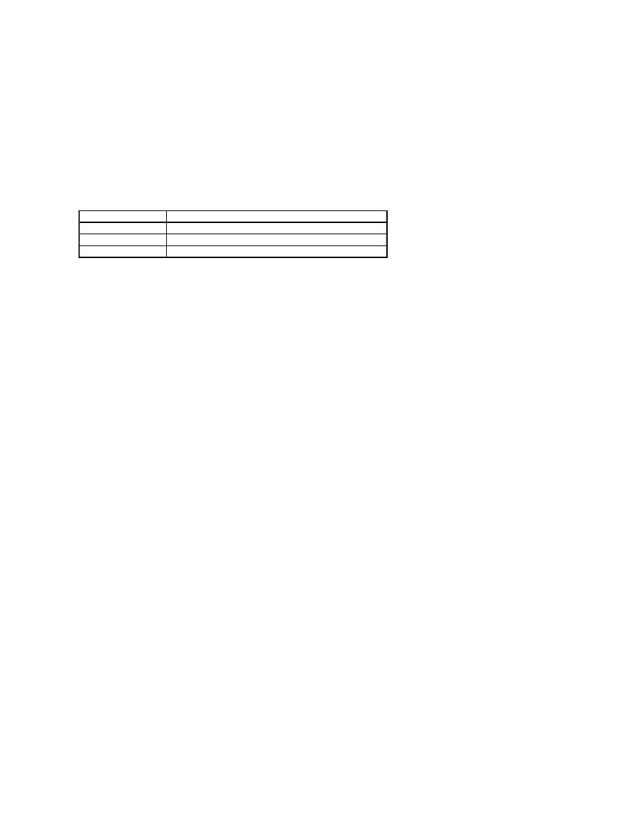
Your computer supports the following ASF alerts and remote capabilities:
For more information about Dell's ASF implementation, see
ASF for Dell Portable Computers
and the
ASF Administrator's Guide for Dell Portable Computers
, which
are available on the Dell Support website at
support.dell.com
.
Alert
Description
Failure to Boot to BIOS
The BIOS did not complete loading upon initiation.
System Password Violation
The system password is invalid (alert occurs after three failed attempts).
Entity Presence
Periodic heartbeats have been transmitted to verify system presence.
