Bosch GLM 50 Professional: инструкция
Раздел: Измерительные инструменты
Тип:
Инструкция к Bosch GLM 50 Professional
Robert Bosch GmbH
Power Tools Division
70745 Leinfelden-Echterdingen
Germany
www.bosch-pt.com
2 609 140 773
(2012.12) O / 190
XXX
GLM 50
Professional
de
Originalbetriebsanleitung
en
Original instructions
fr
Notice originale
es
Manual original
pt
Manual original
it
Istruzioni originali
nl
Oorspronkelijke
gebruiksaanwijzing
da
Original brugsanvisning
sv
Bruksanvisning i original
no
Original driftsinstruks
fi
Alkuperäiset ohjeet
el
Πρωτότυπο οδηγιών χρήσης
tr
Orijinal işletme talimatı
pl
Instrukcja oryginalna
cs
Původní návod k používání
sk
Pôvodný návod na použitie
hu
Eredeti használati utasítás
ru
Оригинальное руководство по эк-
сплуатации
uk
Оригінальна інструкція з
експлуатації
ro
Instrucţiuni originale
bg
Оригинална инструкция
sr
Originalno uputstvo za rad
sl
Izvirna navodila
hr
Originalne upute za rad
et
Algupärane kasutusjuhend
lv
Instrukcijas oriģinālvalodā
lt
Originali instrukcija
cn
原始使用说明书
tw
原始使用說明書
ko
사용 설명서 원본
ar
fa
ςТЎϩХʉ
ЌТϾϦφЍʉ
ʌμВТЎϺυ
ΖЎϩʉ
˒μВЖЙʉʓ
ИͳϞφЁʑ
OBJ_DOKU-25698-004.fm Page 1 Tuesday, December 4, 2012 1:40 PM
2
|
2 609 140 773 | (4.12.12)
Bosch Power Tools
Deutsch. . . . . . . . . . . . . . . . . . . . . . . . . . . . . . . . . . . . . . . . . Seite
6
English . . . . . . . . . . . . . . . . . . . . . . . . . . . . . . . . . . . . . . . . . . Page
11
Français . . . . . . . . . . . . . . . . . . . . . . . . . . . . . . . . . . . . . . . . . Page
18
Español . . . . . . . . . . . . . . . . . . . . . . . . . . . . . . . . . . . . . . . . Página
25
Português . . . . . . . . . . . . . . . . . . . . . . . . . . . . . . . . . . . . . . Página
31
Italiano . . . . . . . . . . . . . . . . . . . . . . . . . . . . . . . . . . . . . . . . Pagina
37
Nederlands . . . . . . . . . . . . . . . . . . . . . . . . . . . . . . . . . . . . . Pagina
43
Dansk . . . . . . . . . . . . . . . . . . . . . . . . . . . . . . . . . . . . . . . . . . . Side
49
Svenska . . . . . . . . . . . . . . . . . . . . . . . . . . . . . . . . . . . . . . . . . Sida
54
Norsk. . . . . . . . . . . . . . . . . . . . . . . . . . . . . . . . . . . . . . . . . . . . Side
59
Suomi . . . . . . . . . . . . . . . . . . . . . . . . . . . . . . . . . . . . . . . . . . . Sivu
64
Ελληνικά . . . . . . . . . . . . . . . . . . . . . . . . . . . . . . . . . . . . . . . Σελίδα
69
Türkçe . . . . . . . . . . . . . . . . . . . . . . . . . . . . . . . . . . . . . . . . . . Sayfa
75
Polski . . . . . . . . . . . . . . . . . . . . . . . . . . . . . . . . . . . . . . . . . Strona
80
Česky . . . . . . . . . . . . . . . . . . . . . . . . . . . . . . . . . . . . . . . . . Strana
87
Slovensky . . . . . . . . . . . . . . . . . . . . . . . . . . . . . . . . . . . . . . Strana
92
Magyar . . . . . . . . . . . . . . . . . . . . . . . . . . . . . . . . . . . . . . . . . Oldal
97
Русский . . . . . . . . . . . . . . . . . . . . . . . . . . . . . . . . . . . . Страница 103
Українська . . . . . . . . . . . . . . . . . . . . . . . . . . . . . . . . . . . Сторінка 110
Română. . . . . . . . . . . . . . . . . . . . . . . . . . . . . . . . . . . . . . . . Pagina 116
Български . . . . . . . . . . . . . . . . . . . . . . . . . . . . . . . . . . Страница 121
Srpski . . . . . . . . . . . . . . . . . . . . . . . . . . . . . . . . . . . . . . . . . Strana 127
Slovensko . . . . . . . . . . . . . . . . . . . . . . . . . . . . . . . . . . . . . . . Stran 133
Hrvatski. . . . . . . . . . . . . . . . . . . . . . . . . . . . . . . . . . . . . . . Stranica 138
Eesti . . . . . . . . . . . . . . . . . . . . . . . . . . . . . . . . . . . . . . . . Lehekülg 143
Latviešu . . . . . . . . . . . . . . . . . . . . . . . . . . . . . . . . . . . . . . Lappuse 148
Lietuviškai. . . . . . . . . . . . . . . . . . . . . . . . . . . . . . . . . . . . . Puslapis 154
中文 . . . . . . . . . . . . . . . . . . . . .
页
159
中文 . . . . . . . . . . . . . . . . . . . . . .頁
165
한국어 . . . . . . . . . . . . . . . . . . . . . . . . . .
면
170
. . . . . . . . . . . . . . . . . . . . . . . . . . . . . .
182
. . . . . . . . . . . . . . . . . . . . . . . . . . . . . .
189
OBJ_BUCH-1444-004.book Page 2 Tuesday, December 4, 2012 1:47 PM
2 609 140 773 | (4.12.12)
Bosch Power Tools
3
|
OBJ_DOKU-25703-004.fm Page 3 Tuesday, December 4, 2012 2:23 PM
4
|
Bosch Power Tools
2 609 140 773 | (4.12.12)
GL
M
250
VF
P r o
f es
sio
nal
17
8
9
1
2
3
4
5
6
7
11
12
14
13
15
16
10
a
b
e f
c
d
c
g
h
GLM 50
P r o f essional
OBJ_BUCH-1444-004.book Page 4 Tuesday, December 4, 2012 1:47 PM
5
|
Bosch Power Tools
2 609 140 773 | (4.12.12)
OBJ_DOKU-25704-004.fm Page 5 Tuesday, December 4, 2012 3:25 PM
6
| Deutsch
2 609 140 773 | (4.12.12)
Bosch Power Tools
Deutsch
Sicherheitshinweise
Sämtliche Anweisungen sind zu lesen und
zu beachten, um mit dem Messwerkzeug
gefahrlos und sicher zu arbeiten. Machen
Sie Warnschilder am Messwerkzeug nie-
mals unkenntlich. BEWAHREN SIE DIESE
ANWEISUNGEN GUT AUF.
Vorsicht – wenn andere als die hienutzt oder andere
Verfahrensweisen ausgeführt werden, kann dies zu ge-
fährlicher Strahlungsexposition führen.
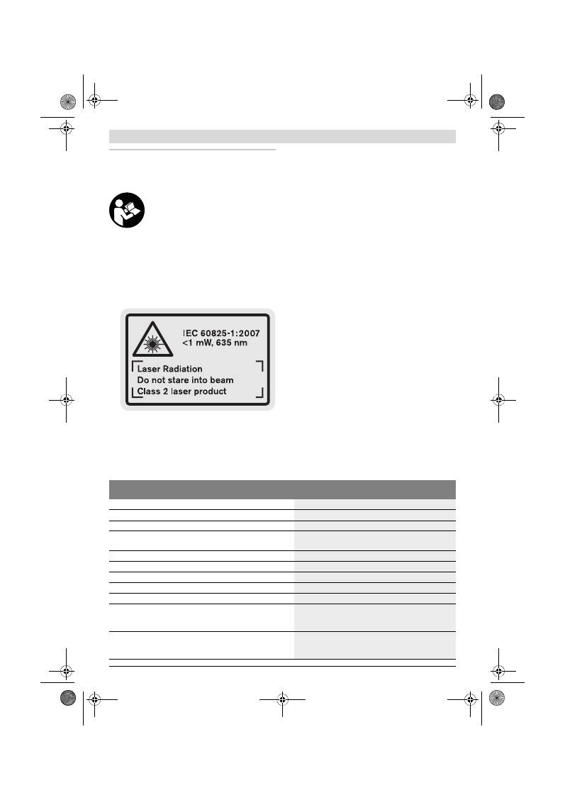
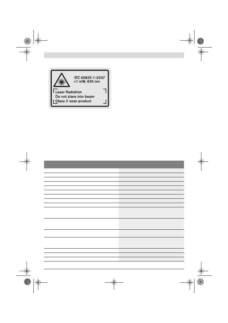
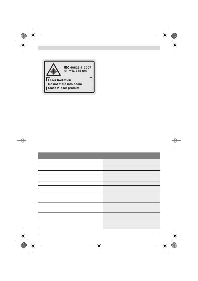
Das Messwerkzeug wird mit einem Warnschild in engli-
scher Sprache ausgeliefert (in der Darstellung des
Messwerkzeugs auf der Grafikseite mit Nummer 15 ge-
kennzeichnet).
Überkleben Sie den englischen Text des Warnschildes
vor der ersten Inbetriebnahme mit dem mitgelieferten
Aufkleber in Ihrer Landessprache.
Richten Sie den Laserstrahl nicht auf Personen oder
Tiere und blicken Sie nicht selbst in den Laserstrahl.
Dieses Messwerkzeug erzeugt Laserstrahlung der Laser-
klasse 2 gemäß IEC 60825-1. Dadurch können Sie Perso-
nen blenden.
Verwenden Sie die Laser-Sichtbrille nicht als Schutz-
brille.
Die Laser-Sichtbrille dient zum besseren Erkennen
des Laserstrahls, sie schützt jedoch nicht vor der Laser-
strahlung.
Verwenden Sie die Laser-Sichtbrille nicht als Sonnen-
brille oder im Straßenverkehr.
Die Laser-Sichtbrille bie-
tet keinen vollständigen UV-Schutz und vermindert die
Farbwahrnehmung.
Lassen Sie das Messwerkzeug von qualifiziertem Fach-
personal und nur mit Original-Ersatzteilen reparieren.
Damit wird sichergestellt, dass die Sicherheit des Mess-
werkzeuges erhalten bleibt.
Lassen Sie Kinder das Laser-Messwerkzeug nicht unbe-
aufsichtigt benutzen.
Sie könnten unbeabsichtigt Perso-
nen blenden.
Arbeiten Sie mit dem Messwerkzeug nicht in explosi-
onsgefährdeter Umgebung, in der sich brennbare Flüs-
sigkeiten, Gase oder Stäube befinden.
Im Messwerk-
zeug können Funken erzeugt werden, die den Staub oder
die Dämpfe entzünden.
Produkt- und Leistungsbeschreibung
Bitte klappen Sie die Ausklappseite mit der Darstellung des
Messwerkzeugs auf, und lassen Sie diese Seite aufgeklappt,
während Sie die Betriebsanleitung lesen.
Bestimmungsgemäßer Gebrauch
Das Messwerkzeug ist bestimmt zum Messen von Entfernun-
gen, Längen, Höhen, Abständen und zum Berechnen von Flä-
chen und Volumina. Das Messwerkzeug ist geeignet zum Mes-
sen im Innen- und Außenbereich.
Technische Daten
Digitaler Laser-Entfernungsmesser
GLM 50
Professional
Sachnummer
3 601 K72 2..
Messbereich
0,05 –50 m
A)
Messgenauigkeit (typisch)
±1,5 mm
B)
Kleinste Anzeigeneinheiter angegebenen Bedienungs- oder Justier-
einrichtungen b
1 mm
Betriebstemperatur
–10 °C...+50 °C
C)
Lagertemperatur
–20 °C...+70 °C
Relative Luftfeuchte max.
90 %
Laserklasse
2
Lasertyp
635 nm, <1 mW
Durchmesser Laserstrahl (bei 25 °C) ca.
– in 10 m Entfernung
– in 50 m Entfernung
6 mm
35 mm
Abschaltautomatik nach ca.
– Laser
– Messwerkzeug (ohne Messung)
20 s
5 min
OBJ_BUCH-1444-004.book Page 6 Tuesday, December 4, 2012 1:47 PM
Deutsch |
7
Bosch Power Tools
2 609 140 773 | (4.12.12)
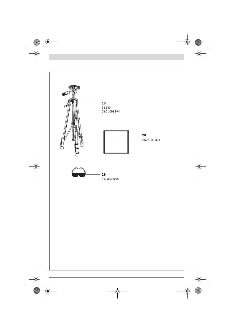
Abgebildete Komponenten
Die Nummerierung der abgebildeten Komponenten bezieht
sich auf die Darstellung des Messwerkzeugs auf der Grafiksei-
te.
1
Display
2
Taste Messen
3
Taste für Flächen-, Volumen- und indirekte Höhenmes-
sung (Pythagoras)
4
Löschtaste / Ein-Aus-Taste **
5
Minustaste
6
Taste Wahl der Bezugsebene
7
Aufnahme Tragschlaufe
8
Plustaste
9
Taste Längen- und Dauermessung
10
Batteriefachdeckel
11
Ausgang Laserstrahlung
12
Empfangslinse
13
Seriennummer
14
1/4"-Gewinde
15
Laser-Warnschild
16
Arretierung des Batteriefachdeckels
17
Schutztasche
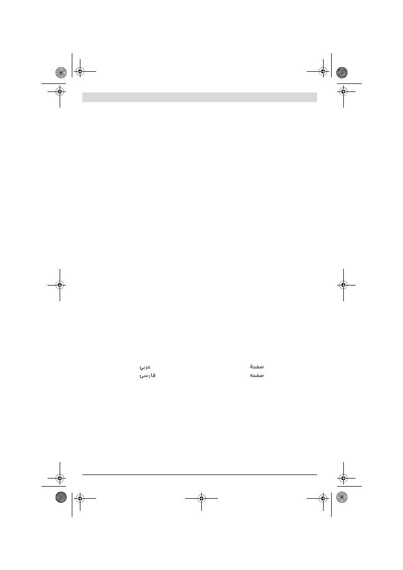
18
Stativ*
19
Laser-Sichtbrille*
20
Laser-Zieltafel*
* Abgebildetes oder beschriebenes Zubehör gehört nicht zum
Standard-Lieferumfang.
** Taste gedrückt halten zum Aufrufen der erweiterten Funktionen.
Anzeigenelemente
a
Messwertzeilen
b
Ergebniszeile
c
Messfunktionen
d
Laser eingeschaltet
e
Bezugsebene der Messung
f
Temperaturwarnung
g
Batteriewarnung
h
Fehleranzeige
„ERROR“
Montage
Batterien einsetzen/wechseln
Für den Betrieb des Messwerkzeugs wird die Verwendung
von Alkali-Mangan-Batterien oder Akkus empfohlen.
Mit 1,2-V-Akkus sind weniger Messungen möglich als mit
1,5-V-Batterien.
Zum Öffnen des Batteriefachdeckels
10
drücken Sie die Arre-
tierung
16
und nehmen den Batteriefachdeckel ab. Setzen
Sie die Batterien bzw. Akkus ein. Achten Sie dabei auf die
richtige Polung entsprechend der Darstellung auf der Innen-
seite des Batteriefachs.
Achten Sie beim Einsetzen der Batterien bzw. Akkus auf die
richtige Polung entsprechend der Abbildung im Batteriefach.
Erscheint das Batteriesymbol
erstmals im Display, dann
sind noch mindestens 100 Einzelmessungen möglich. Die
Funktion Dauermessung ist deaktiviert.
Batterien
Akkuzellen
2 x 1,5 V LR03 (AAA)
2 x 1,2 V HR03 (AAA)
Batterielebensdauer ca.
– Einzelmessungen
– Dauermessung
10000
D)
2,5 h
D)
Gewicht entsprechend EPTA-Procedure 01/2003
0,14 kg
Maße
53 x 114 x 30 mm
Schutzart
IP 54 (staub- und spritzwassergeschützt)
Digitaler Laser-Entfernungsmesser
GLM 50
Professional
A) Die Reichweite wird größer, je besser das Laserlicht von der Oberfläche des Zieles zurückgeworfen wird (streuend, nicht spiegelnd) und je heller
der Laserpunkt gegenüber der Umgebungshelligkeit ist (Innenräume, Dämmerung). Bei ungünstigen Bedingungen (z.B. Messen im Außenbereich mit
starker Sonneneinstrahlung) kann es notwendig sein, die Zieltafel zu verwenden.
B) Bei Messung ab Hinterkante des Messwerkzeugs. Bei ungünstigen Bedingungen wie z.B. starker Sonneneinstrahlung oder schlecht reflektierender
Oberfläche beträgt die maximale Abweichung
±
10 mm auf 50 m. Bei günstigen Bedingungen ist mit einem Einfluss von
±
0,05 mm/m zu rechnen.
C) In der Funktion Dauermessung beträgt die max. Betriebstemperatur +40
°C
.
D) Mit 1,2-V-Akkuzellen sind weniger Messungen möglich als mit 1,5-V-Batterien. Die angegebene Batterielebensdauer bezieht sich auf Messungen
ohne Displaybeleuchtung.
Zur eindeutigen Identifizierung Ihres Messwerkzeugs dient die Seriennummer
13
auf dem Typenschild.
Längenmessung
Dauermessung
Flächenmessung
Volumenmessung
Einfache Pythagorasmessung
OBJ_BUCH-1444-004.book Page 7 Tuesday, December 4, 2012 1:47 PM
8
| Deutsch
2 609 140 773 | (4.12.12)
Bosch Power Tools
Wenn das Batteriesymbol
blinkt, müssen Sie die Batterien
bzw. Akkuzellen auswechseln. Messungen sind nicht mehr
möglich.
Ersetzen Sie immer alle Batterien bzw. Akkus gleichzeitig.
Verwenden Sie nur Batterien oder Akkus eines Herstellers
und mit gleicher Kapazität.
Nehmen Sie die Batterien bzw. Akkus aus dem Mess-
werkzeug, wenn Sie es längere Zeit nicht benutzen.
Die
Batterien und Akkus können bei längerer Lagerung korro-
dieren und sich selbst entladen.
Betrieb
Inbetriebnahme
Lassen Sie das eingeschaltete Messwerkzeug nicht un-
beaufsichtigt und schalten Sie das Messwerkzeug nach
Gebrauch ab.
Andere Personen könnten vom Laserstrahl
geblendet werden.
Schützen Sie das Messwerkzeug vor Nässe und direk-
ter Sonneneinstrahlung.
Setzen Sie das Messwerkzeug keinen extremen Tem-
peraturen oder Temperaturschwankungen aus.
Lassen
Sie es z.B. nicht längere Zeit im Auto liegen. Lassen Sie das
Messwerkzeug bei größeren Temperaturschwankungen
erst austemperieren, bevor Sie es in Betrieb nehmen. Bei
extremen Temperaturen oder Temperaturschwankungen
kann die Präzision des Messwerkzeugs beeinträchtigt wer-
den.
Vermeiden Sie heftige Stöße oder Stürze des Mess-
werkzeuges.
Nach starken äußeren Einwirkungen auf das
Messwerkzeug sollten Sie vor dem Weiterarbeiten immer
eine Genauigkeitsüberprüfung durchführen (siehe
„Genauigkeitsüberprüfung der Entfernungsmessung“,
Seite 10).
Ein-/Ausschalten
Zum
Einschalten
des Messwerkzeugs haben Sie folgende
Möglichkeiten:
– Drücken auf die Ein-Aus-Taste
4
: Das Messwerkzeug wird
eingeschaltet und befindet sich in der Funktion Längen-
messung. Der Laser wird nicht eingeschaltet.
– Drücken auf die Taste Messen
2
: Messwerkzeug und Laser
werden eingeschaltet. Das Messwerkzeug befindet sich in
der Funktion Längenmessung.
Richten Sie den Laserstrahl nicht auf Personen oder
Tiere und blicken Sie nicht selbst in den Laserstrahl,
auch nicht aus größerer Entfernung.
Zum
Ausschalten
des Messwerkzeugs drücken Sie lange auf
die Ein-Aus-Taste
4
.
Wird ca. 5 min lang keine Taste am Messwerkzeug gedrückt,
dann schaltet sich das Messwerkzeug zur Schonung der Bat-
terien automatisch ab.
Messvorgang
Nach dem Einschalten durch Drücken auf die Taste Messen
2
befindet sich das Messwerkzeug immer in der Funktion Län-
genmessung. Andere Messfunktionen können Sie durch Drü-
cken der jeweiligen Funktionstaste einstellen (siehe „Mess-
funktionen“, Seite 8).
Als Bezugsebene für die Messung ist nach dem Einschalten
die Hinterkante des Messwerkzeugs ausgewählt. Durch Drü-
cken der Taste Bezugsebene
6
können Sie die Bezugsebene
ändern (siehe „Bezugsebene wählen“, Seite 8).
Legen Sie das Messwerkzeug mit der gewählten Bezugsebene
an den gewünschten Startpunkt der Messung (z.B. Wand) an.
Drücken Sie zum Einschalten des Laserstrahls kurz auf die
Taste Messen
2
.
Richten Sie den Laserstrahl nicht auf Personen oder
Tiere und blicken Sie nicht selbst in den Laserstrahl,
auch nicht aus größerer Entfernung.
Visieren Sie mit dem Laserstrahl die Zielfläche an. Drücken
Sie zum Auslösen der Messung erneut kurz auf die Taste Mes-
sen
2
.
In der Funktion Dauermessung beginnt die Messung sofort
beim Einschalten der Funktion.
Der Messwert erscheint typischerweise innerhalb von 0,5 s
und spätestens nach 4 s. Die Dauer der Messung hängt ab von
der Entfernung, den Lichtverhältnissen und den Reflexionsei-
genschaften der Zielfläche. Nach Beendigung der Messung
wird der Laserstrahl automatisch abgeschaltet.
Erfolgt ca. 20 s nach dem Anvisieren keine Messung, schaltet
sich der Laserstrahl zur Schonung der Batterien automatisch
ab.
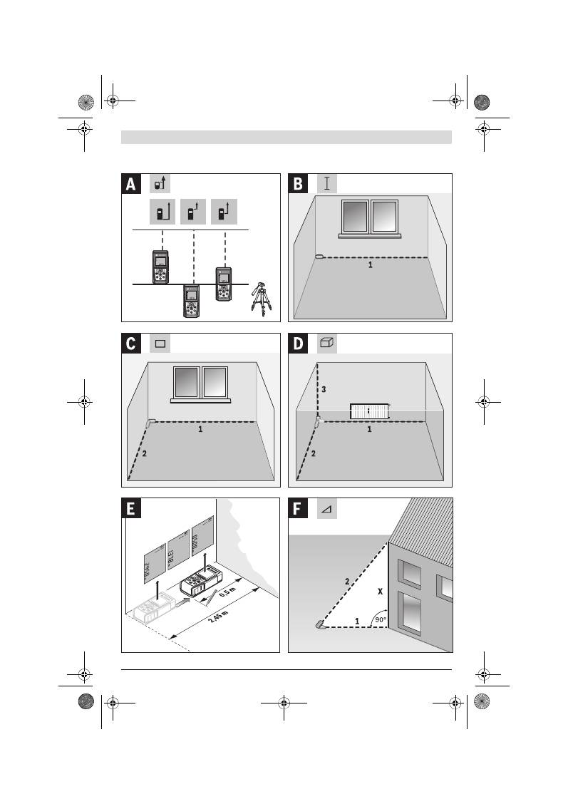
Bezugsebene wählen (siehe Bild A)
Für die Messung können Sie unter drei verschiedenen Be-
zugsebenen wählen:
– der Hinterkante des Messwerkzeugs (z.B. beim Anlegen an
Wände),
– der Vorderkante des Messwerkzeugs (z.B. beim Messen
ab einer Tischkante),
– der Mitte des Gewindes
14
(z.B. für Messungen mit Sta-
tiv).
Drücken Sie zur Auswahl der Bezugsebene die Taste
6
so oft,
bis im Display die gewünschte Bezugsebene angezeigt wird.
Nach jedem Einschalten des Messwerkzeugs ist die Hinter-
kante des Messwerkzeugs als Bezugsebene voreingestellt.
Displaybeleuchtung
Die Displaybeleuchtung wird je nach Umgebungshelligkeit au-
tomatisch aktiviert. Erfolgt nach dem Einschalten der Display-
beleuchtung kein Tastendruck, wird diese zur Schonung der
Batterien gedimmt.
Messfunktionen
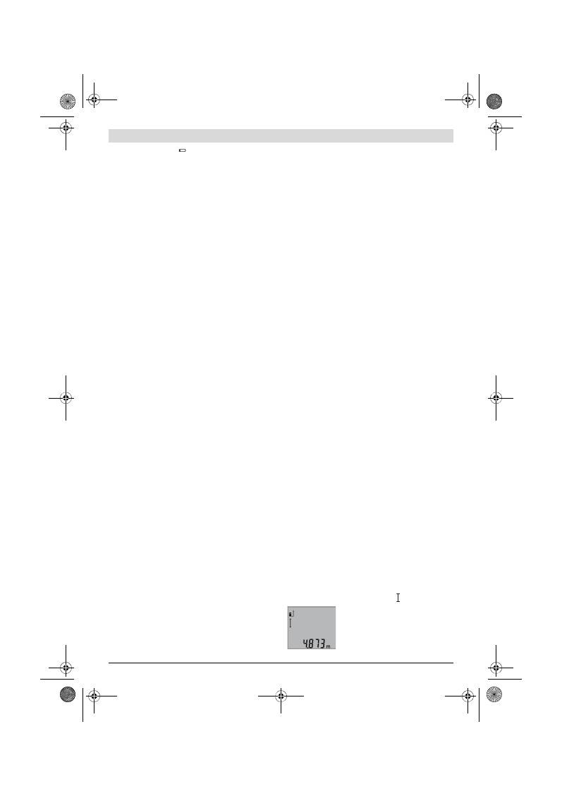
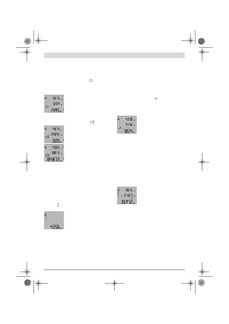
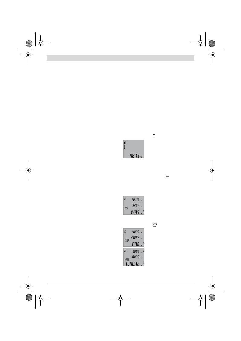
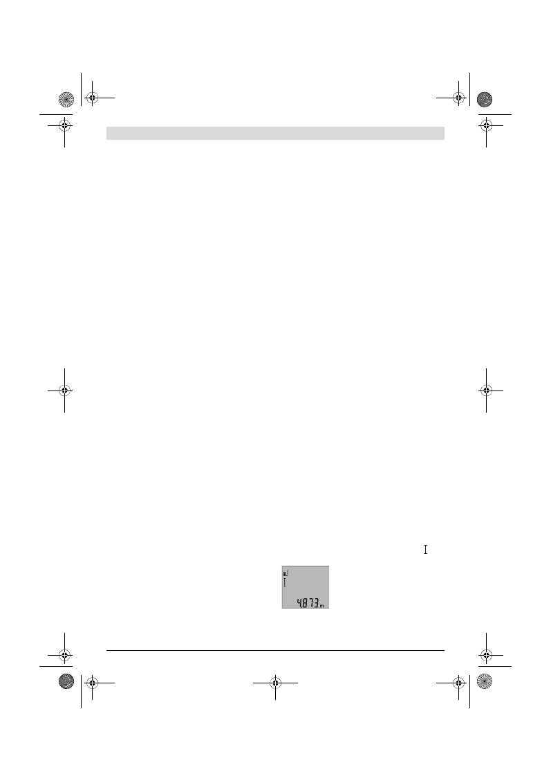
Einfache Längenmessung (siehe Bild B)
Drücken Sie für Längenmessungen die Taste
9
so oft, bis im
Display die Anzeige für Längenmessung erscheint.
Drücken Sie zum Einschalten des Lasers
und zum Messen jeweils einmal kurz auf
die Taste Messen
2
.
Der Messwert wird in der Ergebniszeile
b
angezeigt.
OBJ_BUCH-1444-004.book Page 8 Tuesday, December 4, 2012 1:47 PM
Deutsch |
9
Bosch Power Tools
2 609 140 773 | (4.12.12)
Bei mehreren Längenmessungen hintereinander werden die
Ergebnisse der letzten Messungen in den Messwertzeilen
a
angezeigt.
Flächenmessung (siehe Bild C)
Drücken Sie für Flächenmessungen die Taste
3
so oft, bis im
Display die Anzeige für Flächenmessung
erscheint.
Messen Sie anschließend Länge und Breite nacheinander wie
bei einer Längenmessung. Zwischen den beiden Messungen
bleibt der Laserstrahl eingeschaltet.
Nach Abschluss der zweiten Messung
wird die Fläche automatisch errechnet
und in der Ergebniszeile
b
angezeigt. Die
Einzelmesswerte stehen in den Mess-
wertzeilen
a
.
Volumenmessung (siehe Bild D)
Drücken Sie für Volumenmessungen die Taste
3
so oft, bis im
Display die Anzeige für Volumenmessung
erscheint.
Messen Sie anschließend Länge, Breite
und Höhe nacheinander wie bei einer
Längenmessung. Zwischen den drei Mes-
sungen bleibt der Laserstrahl eingeschal-
tet.
Nach Abschluss der dritten Messung wird
das Volumen automatisch errechnet und
in der Ergebniszeile
b
angezeigt. Die Ein-
zelmesswerte stehen in den Messwertzei-
len
a
.
Werte über 999999 m
3
können nicht angezeigt werden, im
Display erscheint
„ERROR“
. Teilen Sie das zu messende Vo-
lumen in Einzelmessungen auf, deren Werte Sie separat be-
rechnen und dann zusammenfassen.
Dauermessung (siehe Bild E)
Bei der Dauermessung kann das Messwerkzeug relativ zum
Ziel bewegt werden, wobei der Messwert ca. alle 0,5 s aktua-
lisiert wird. Sie können sich z.B. von einer Wand bis zum ge-
wünschten Abstand entfernen, die aktuelle Entfernung ist
stets ablesbar.
Für Dauermessungen drücken Sie die Taste
9
, bis im Display
die Anzeige für Dauermessung erscheint. Drücken Sie zum
Start der Dauermessung die Taste Messen
2
.
Der aktuelle Messwert wird in der Ergeb-
niszeile
b
angezeigt.
Durch Drücken der Taste Messen
2
been-
den Sie die Dauermessung. Der letzte
Messwert wird in der Ergebniszeile
b
an-
gezeigt. Erneutes Drücken der Taste Mes-
sen
2
startet die Dauermessung von Neuem.
Die Dauermessung schaltet nach 5 min automatisch ab. Der
letzte Messwert bleibt in der Ergebniszeile
b
angezeigt.
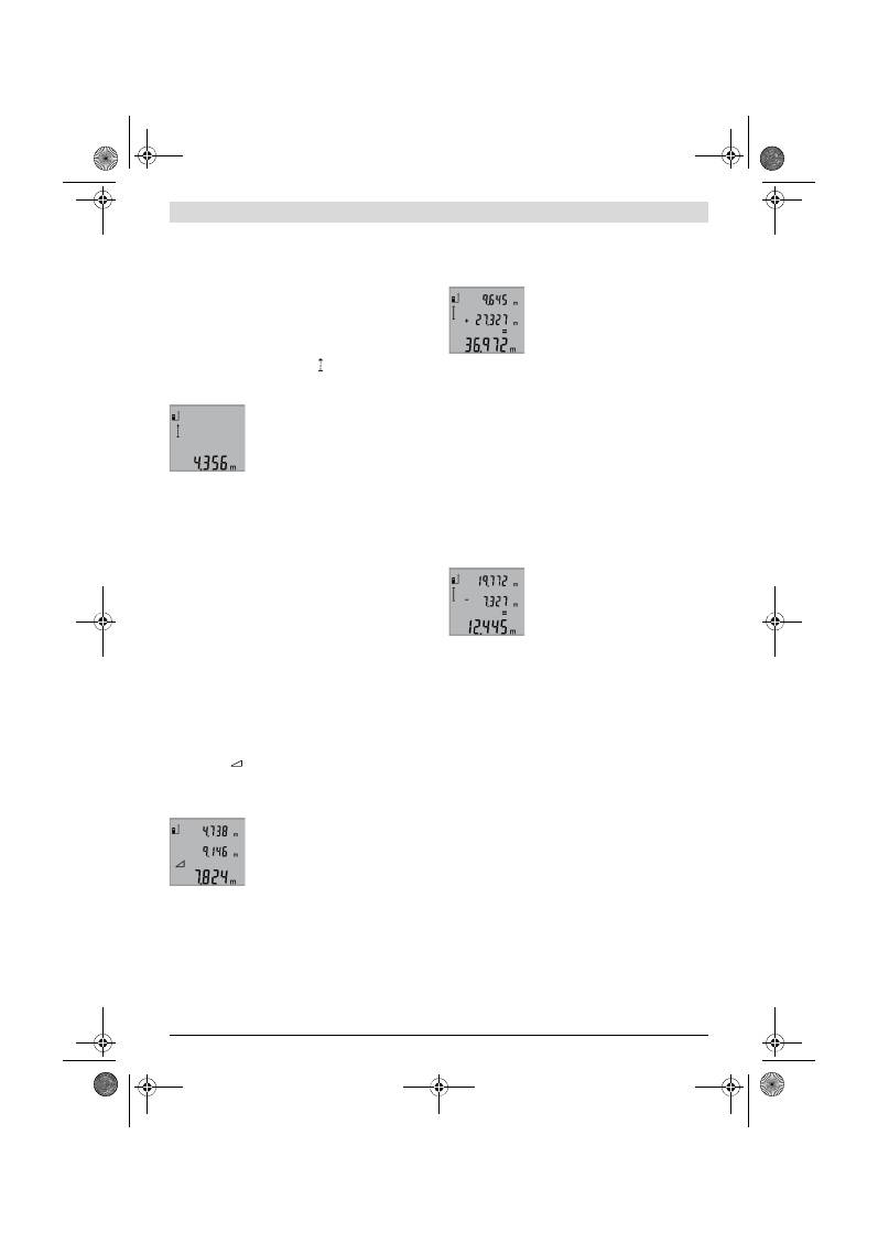
Indirekte Höhenmessung / Einfache Pythagorasmessung
(siehe Bild F)
Die indirekte Höhenmessung dient zum Ermitteln von Entfer-
nungen, die nicht direkt zu messen sind, weil ein Hindernis
den Strahlengang behindern würde oder keine Zielfläche als
Reflektor zur Verfügung steht. Korrekte Ergebnisse werden
nur dann erreicht, wenn die bei der jeweiligen Messung gefor-
derten rechten Winkel exakt eingehalten werden (Satz des
Pythagoras).
Achten Sie darauf, dass der Bezugspunkt der Messung (z.B.
Hinterkante des Messwerkzeugs) bei allen Einzelmessungen
innerhalb eines Messvorgangs an exakt der gleichen Stelle
bleibt.
Zwischen den Einzelmessungen bleibt der Laserstrahl einge-
schaltet.
Drücken Sie die Taste
3
so oft, bis im Display die Anzeige für
die einfache Pythagorasmessung
erscheint.
Messen Sie wie bei einer Längenmessung die Strecken
„1“
und
„2“
in dieser Reihenfolge. Achten Sie darauf, dass zwi-
schen der Strecke
„1“
und der gesuchten Stecke
„X“
ein
rechter Winkel besteht.
Nach Abschluss der letzten Messung wird
das Ergebnis für die gesuchte Strecke
„X“
in der Ergebniszeile
b
angezeigt. Die Ein-
zelmesswerte stehen in den Messwertzei-
len
a
.
Messwerte löschen
Durch kurzes Drücken der Taste
4
können Sie in allen Mess-
funktionen den zuletzt ermittelten Einzelmesswert löschen.
Durch mehrmaliges kurzes Drücken der Taste werden die Ein-
zelmesswerte in umgekehrter Reihenfolge gelöscht.
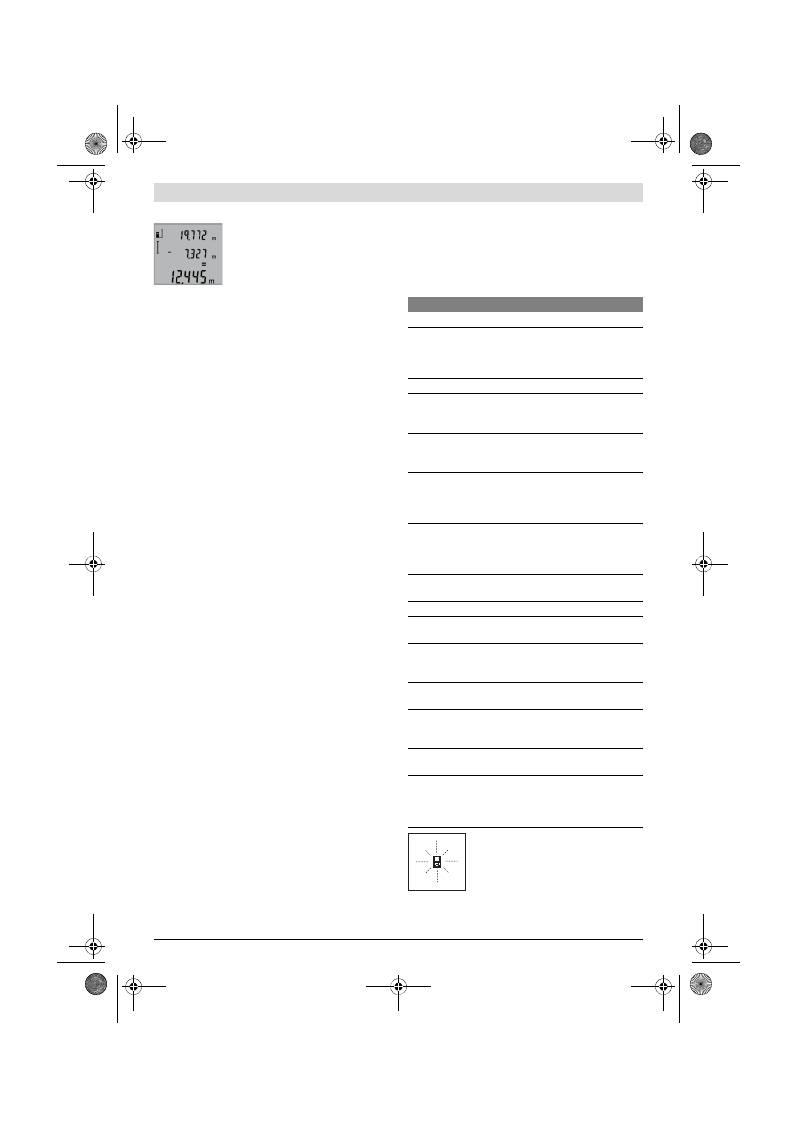
Messwerte addieren
Um Messwerte zu addieren, führen Sie zuerst eine beliebige
Messung durch. Drücken Sie dann die Plustaste
8
. Im Display
erscheint zur Bestätigung
„+“
.
Um Volumen oder Flächen zu addieren, drücken Sie nach dem
ersten abgeschlossenen Messvorgang die Plustaste
8
. Im Dis-
play erscheint zur Bestätigung
„+“
links vom Volumen-/Flä-
chensymbol.
Führen Sie dann eine zweite Messung durch.
Drücken Sie zur Abfrage der Summe bei-
der Messungen nochmals die Plustaste
8
.
Die Berechnung wird in den Messwertzei-
len
a
angezeigt, die Summe steht in der
Ergebniszeile
b
.
Nach Berechnung der Summe können zu diesem Ergebnis
weitere Messwerte addiert werden, wenn vor der Messung je-
weils die Plustaste
8
gedrückt wird.
Hinweise zur Addition:
– Längen-, Flächen- und Volumenwerte können nicht ge-
mischt addiert werden. Werden z.B. ein Längen- und ein
Flächenwert addiert, erscheint beim Drücken der Plustas-
te
8
kurz
„ERROR“
im Display. Danach wechselt das Mess-
werkzeug in die zuletzt aktive Messfunktion.
– Es wird jeweils das Ergebnis einer Messung (z.B. Volumen-
wert) addiert, bei Dauermessungen der in der Ergebniszei-
le
b
angezeigte Messwert. Die Addition von Einzelmess-
werten aus den Messwertzeilen
a
ist nicht möglich.
OBJ_BUCH-1444-004.book Page 9 Tuesday, December 4, 2012 1:47 PM
10
| Deutsch
2 609 140 773 | (4.12.12)
Bosch Power Tools
Messwerte subtrahieren
Zur Subtraktion von Messwerten drücken
Sie die Minustaste
5
, im Display erscheint
zur Bestätigung
„–“
. Das weitere Vorge-
hen ist analog zu „Messwerte addieren“.
Arbeitshinweise
Allgemeine Hinweise
Die Empfangslinse
12
und der Ausgang der Laserstrahlung
11
dürfen bei einer Messung nicht abgedeckt sein.
Das Messwerkzeug darf während einer Messung nicht bewegt
werden (mit Ausnahme der Funktion Dauermessung). Legen
Sie deshalb das Messwerkzeug möglichst an eine feste An-
schlag- oder Auflagefläche an.
Einflüsse auf den Messbereich
Der Messbereich hängt von den Lichtverhältnissen und den
Reflexionseigenschaften der Zielfläche ab. Verwenden Sie
zur besseren Sichtbarkeit des Laserstrahls bei Arbeiten im
Außenbereich und bei starker Sonneneinstrahlung die Laser-
Sichtbrille
19
(Zubehör) und die Laser-Zieltafel
20
(Zube-
hör), oder schatten Sie die Zielfläche ab.
Einflüsse auf das Messergebnis
Aufgrund physikalischer Effekte kann nicht ausgeschlossen
werden, dass es beim Messen auf verschiedenen Oberflä-
chen zu Fehlmessungen kommt. Dazu zählen:
– transparente Oberflächen (z.B. Glas, Wasser),
– spiegelnde Oberflächen (z.B. poliertes Metall, Glas),
– poröse Oberflächen (z.B. Dämmmaterialien),
– strukturierte Oberflächen (z.B. Rauputz, Naturstein).
Verwenden Sie gegebenenfalls auf diesen Oberflächen die La-
ser-Zieltafel
20
(Zubehör).
Fehlmessungen sind außerdem auf schräg anvisierten Zielflä-
chen möglich.
Ebenso können Luftschichten mit unterschiedlichen Tempe-
raturen oder indirekt empfangene Reflexionen den Messwert
beeinflussen.
Genauigkeitsüberprüfung der Entfernungsmessung
Sie können die Genauigkeit der Entfernungsmessung wie
folgt überprüfen:
– Wählen Sie eine auf Dauer unveränderliche Messstrecke
von ca. 1 bis 10 m Länge, deren Länge Ihnen exakt be-
kannt ist (z.B. Raumbreite, Türöffnung). Die Messstrecke
muss im Innenraum liegen, die Zielfläche der Messung glatt
und gut reflektierend sein.
– Messen Sie die Strecke 10-mal hintereinander.
Die Abweichung der Einzelmessungen vom Mittelwert darf
maximal ±2 mm betragen. Protokollieren Sie die Messungen,
um zu einem späteren Zeitpunkt die Genauigkeit vergleichen
zu können.
Arbeiten mit dem Stativ (Zubehör)
Die Verwendung eines Stativs ist besonders bei größeren Ent-
fernungen notwendig. Setzen Sie das Messwerkzeug mit dem
1/4"-Gewinde
14
auf die Schnellwechselplatte des Stativs
18
oder eines handelsüblichen Fotostativs auf. Schrauben Sie es
mit der Feststellschraube der Schnellwechselplatte fest.
Stellen Sie die Bezugsebene für Messungen mit Stativ durch
Drücken der Taste
6
entsprechend ein (Bezugsebene Gewin-
de).
Fehler
–
Ursachen und Abhilfe
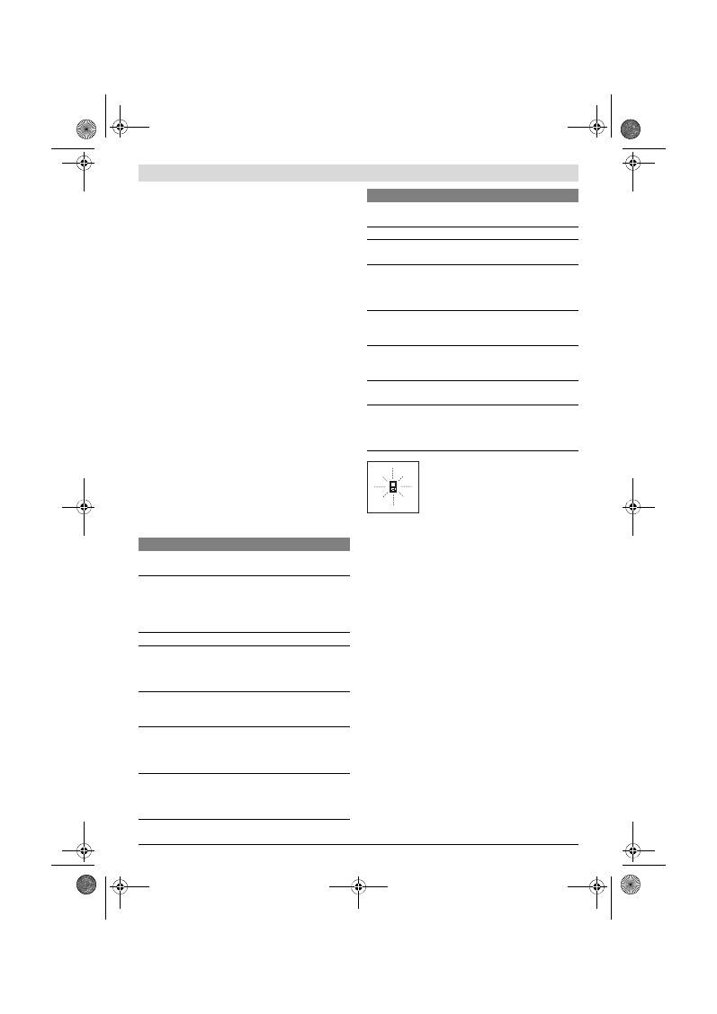
Das Messwerkzeug überwacht die korrekte
Funktion bei jeder Messung. Wird ein De-
fekt festgestellt, blinkt im Display nur noch
das nebenstehende Symbol. In diesem Fall,
oder wenn die oben genannten Abhilfemaß-
nahmen einen Fehler nicht beseitigen kön-
nen, führen Sie das Messwerkzeug über Ihren Händler dem
Bosch-Kundendienst zu.
Ursache
Abhilfe
Temperaturwarnung (f) blinkt, Messung nicht möglich
Messwerkzeug ist außerhalb der
Betriebstemperatur von –10 °C
bis +50 °C (in der Funktion Dauer-
messung bis +40 °C).
Abwarten, bis das Mess-
werkzeug Betriebstem-
peratur erreicht
Anzeige „ERROR“ im Display
Addition/Subtraktion von Mess-
werten mit unterschiedlichen
Maßeinheiten
Nur Messwerte mit glei-
chen Maßeinheiten ad-
dieren/subtrahieren
Winkel zwischen Laserstrahl und
Ziel ist zu spitz.
Winkel zwischen Laser-
strahl und Ziel vergrö-
ßern
Zielfläche reflektiert zu stark (z.B.
Spiegel) bzw. zu schwach (z.B.
schwarzer Stoff), oder Umge-
bungslicht ist zu stark.
Laser-Zieltafel
20
(Zu-
behör) verwenden
Ausgang Laserstrahlung
11
bzw.
Empfangslinse
12
sind beschla-
gen (z.B. durch schnellen Tempe-
raturwechsel).
Mit weichem Tuch Aus-
gang Laserstrahlung
11
bzw. Empfangslinse
12
trockenreiben
Berechneter Wert ist größer als
999999 m/m
2
/m
3
.
Berechnung in Zwi-
schenschritte aufteilen
Messergebnis unplausibel
Zielfläche reflektiert nicht eindeu-
tig (z.B. Wasser, Glas).
Zielfläche abdecken
Ausgang Laserstrahlung
11
bzw.
Empfangslinse
12
ist verdeckt.
Ausgang Laserstrahlung
11
bzw. Empfangslinse
12
freihalten
Falsche Bezugsebene eingestellt
Bezugsebene passend
zur Messung wählen
Hindernis im Verlauf des Laser-
strahls
Laserpunkt muss kom-
plett auf Zielfläche lie-
gen.
Die Anzeige bleibt unverändert oder das Messwerkzeug
reagiert unerwartet auf Tastendruck
Fehler in der Software
Entnehmen Sie die Bat-
terien und starten Sie
das Messwerkzeug nach
Wiedereinlegen erneut.
OBJ_BUCH-1444-004.book Page 10 Tuesday, December 4, 2012 1:47 PM
English |
11
Bosch Power Tools
2 609 140 773 | (4.12.12)
Wartung und Service
Wartung und Reinigung
Lagern und transportieren Sie das Messwerkzeug nur in der
mitgelieferten Schutztasche.
Halten Sie das Messwerkzeug stets sauber.
Tauchen Sie das Messwerkzeug nicht ins Wasser oder andere
Flüssigkeiten.
Wischen Sie Verschmutzungen mit einem feuchten, weichen
Tuch ab. Verwenden Sie keine Reinigungs- oder Lösemittel.
Pflegen Sie insbesondere die Empfangslinse
12
mit der glei-
chen Sorgfalt, mit der Brille oder Linse eines Fotoapparats
behandelt werden müssen.
Sollte das Messwerkzeug trotz sorgfältiger Herstellungs- und
Prüfverfahren einmal ausfallen, ist die Reparatur von einer au-
torisierten Kundendienststelle für Bosch-Elektrowerkzeuge
ausführen zu lassen. Öffnen Sie das Messwerkzeug nicht
selbst.
Geben Sie bei allen Rückfragen und Ersatzteilbestellungen
bitte unbedingt die 10-stellige Sachnummer laut Typenschild
des Messwerkzeugs an.
Senden Sie im Reparaturfall das Messwerkzeug in der Schutz-
tasche
17
ein.
Kundendienst und Anwendungsberatung
Der Kundendienst beantwortet Ihre Fragen zu Reparatur und
Wartung Ihres Produkts sowie zu Ersatzteilen. Explosions-
zeichnungen und Informationen zu Ersatzteilen finden Sie
auch unter:
www.bosch-pt.com
Das Bosch-Anwendungsberatungs-Team hilft Ihnen gerne bei
Fragen zu unseren Produkten und deren Zubehör.
www.powertool-portal.de
, das Internetportal für Handwer-
ker und Heimwerker.
Deutschland
Robert Bosch GmbH
Servicezentrum Elektrowerkzeuge
Zur Luhne 2
37589 Kalefeld – Willershausen
Unter www.bosch-pt.com können Sie online Ersatzteile be-
stellen oder Reparaturen anmelden.
Kundendienst: Tel.: (0711) 40040480
Fax: (0711) 40040481
E-Mail: Servicezentrum.Elektrowerkzeuge@de.bosch.com
Anwendungsberatung: Tel.: (0711) 40040480
Fax: (0711) 40040482
E-Mail: Anwendungsberatung.pt@de.bosch.com
Österreich
Tel.: (01) 797222010
Fax: (01) 797222011
E-Mail: service.elektrowerkzeuge@at.bosch.com
Schweiz
Tel.: (044) 8471511
Fax: (044) 8471551
E-Mail: Aftersales.Service@de.bosch.com
Luxemburg
Tel.: +32 2 588 0589
Fax: +32 2 588 0595
E-Mail: outillage.gereedschap@be.bosch.com
Entsorgung
Messwerkzeuge, Zubehör und Verpackungen sollen einer um-
weltgerechten Wiederverwertung zugeführt werden.
Werfen Sie Messwerkzeuge und Akkus/Batterien nicht in den
Hausmüll!
Nur für EU-Länder:
Gemäß der europäischen Richtlinie
2002/96/EG müssen nicht mehr ge-
brauchsfähige Messwerkzeuge und gemäß
der europäischen Richtlinie 2006/66/EG
müssen defekte oder verbrauchte Ak-
kus/Batterien getrennt gesammelt und ei-
ner umweltgerechten Wiederverwendung zugeführt werden.
Nicht mehr gebrauchsfähige Akkuzellen/Batterien können di-
rekt abgegeben werden bei:
Deutschland
Recyclingzentrum Elektrowerkzeuge
Osteroder Landstraße 337589 Kalefeld
Schweiz
Batrec AG
3752 Wimmis BE
Änderungen vorbehalten.
English
Safety Notes
Working safely with the measuring tool is
possible only when the operating and safe-
ty information are read completely and the
instructions contained therein are strictly
followed. Never make warning labels on
the measuring tool unrecognisable. SAVE
THESE INSTRUCTIONS.
Caution – The use of other operating or adjusting
equipment or the application of other processing meth-
ods than those mentioned here, can lead to dangerous
radiation exposure.
The measuring tool is delivered with a warning label in
English language (marked with the number 15 in the
OBJ_BUCH-1444-004.book Page 11 Tuesday, December 4, 2012 1:47 PM
12
| English
2 609 140 773 | (4.12.12)
Bosch Power Tools
representation of the measuring tool on the graphic
page).
Do not direct the laser beam at persons or animals and
do not stare into the laser beam yourself.
This measur-
ing tool produces laser class 2 laser radiation according to
IEC 60825-1. This can lead to persons being blinded.
Do not use the laser viewing glasses as safety goggles.
The laser viewing glasses are used for improved visualisa-
tion of the laser beam, but they do not protect against laser
radiation.
Do not use the laser viewing glasses as sun glasses or in
traffic.
The laser viewing glasses do not afford complete
UV protection and reduce colour perception.
Have the measuring tool repaired only through quali-
fied specialists using original spare parts.
This ensures
that the safety of the measuring tool is maintained.
Do not allow children to use the laser measuring tool
without supervision.
They could unintentionally blind
other persons or themselves.
Do not operate the measuring tool in explosive environ-
ments, such as in the presence of flammable liquids,
gases or dusts.
Sparks can be created in the measuring
tool which may ignite the dust or fumes.
Product Description and Specifica-
tions
Please unfold the fold-out page with the representation of the
measuring tool and leave it unfolded while reading the operat-
ing instructions.
Intended Use
The measuring tool is intended for measuring distances,
lengths, heights, clearances, and for the calculation of areas
and volumes. The measuring tool is suitable for measuring in-
doors and outdoors.
Technical Data
Digital Laser Rangefinder
GLM 50
Professional
Article number
3 601 K72 2..
Measuring range
0.05 –50 m
A)
Measuring accuracy (typically)
±1.5 mm
B)
Lowest indication unit
1 mm
Operating temperature
–10 °C...+50 °C
C)
Storage temperature
–20 °C...+70 °C
Relative air humidity, max.
90 %
Laser class
2
Laser type
635 nm, <1 mW
Laser beam diameter (at 25 °C) approx.
– at 10 m distance
– at 50 m distance
6 mm
35 mm
Automatic switch-off after approx.
– Laser
– Measuring tool (without measurement)
20 s
5 min
Batteries
Rechargeable batteries
2 x 1.2 V LR03 (AAA)
2 x 1.2 V HR03 (AAA)
Battery live, approximately
– Individual measurements
– Continuous measurement
10000
D)
2.5 h
D)
Weight according to EPTA-Procedure 01/2003
0.14 kg
Dimensions
53 x 114 x 30 mm
Degree of protection
IP 54 (dust and splash water protected)
OBJ_BUCH-1444-004.book Page 12 Tuesday, December 4, 2012 1:47 PM
English |
13
Bosch Power Tools
2 609 140 773 | (4.12.12)
Product Features
The numbering of the product features shown refers to the il-
lustration of the measuring tool on the graphic page.
1
Display
2
Measuring button
3
Button for area/surface, volume and indirect height
measurement (Pythagoras)
4
Delete / On/Off button **
5
Minus button
6
Button for selection of the reference level
7
Fixture for carrying strap
8
Plus button
9
Length and continuous measurement button
10
Battery lid
11
Laser beam outlet
12
Reception lens
13
Serial number
14
1/4" thread
15
Laser warning label
16
Latch of battery lid
17
Protective pouch
18
Tripod*
19
Laser viewing glasses*
20
Laser target plate*
* The accessories illustrated or described are not included as
standard delivery.
** Keep button pressed to call up the extended functions.
Display Elements
a
Measured-value lines
b
Result line
c
Measuring functions
d
Laser, switched on
e
Measurement reference level
f
Temperature warning
g
Battery low indicator
h “ERROR”
indication
Assembly
Inserting/Replacing the Battery
Using alkali-manganese or rechargeable batteries is recom-
mended for operation of the measuring tool.
Less measurements are possible when using 1.2 V recharge-
able batteries than with 1.5 V batteries.
To open the battery lid
10
, press the latch
16
and remove the
battery lid. Insert the batteries/rechargeable batteries. When
inserting, pay attention to the correct polarity according to
the representation on the inside of the battery compartment.
When inserting the batteries/rechargeable batteries, pay at-
tention to the correct polarity according to the representation
on the inside of the battery compartment.
When the battery symbol
appears for the first time on the
display, at least 100 individual measurements are still possi-
ble. The continuous measurement mode is deactivated.
When the battery symbol
flashes, the batteries/recharge-
able batteries must be replaced. Measurements are no longer
possible.
Always replace all batteries/rechargeable batteries at the
same time. Do not use different brands or types of batter-
ies/rechargeable batteries together.
Remove the batteries/rechargeable batteries from the
measuring tool when not using it for longer periods.
When storing for longer periods, the batteries/rechargea-
ble batteries can corrode and discharge themselves.
Operation
Initial Operation
Do not leave the switched on measuring tool unattend-
ed and switch the measuring tool off after use.
Other
persons could be blinded by the laser beam.
Protect the measuring tool against moisture and direct
sun light.
Do not subject the measuring tool to extreme tempera-
tures or variations in temperature.
As an example, do
not leave it in vehicles for long time. In case of large varia-
tions in temperature, allow the measuring tool to adjust to
the ambient temperature before putting it into operation.
In case of extreme temperatures or variations in tempera-
ture, the accuracy of the measuring tool can be impaired.
Avoid heavy impact to or falling down of the measuring
tool.
After severe exterior effects to the measuring tool, it
A) The working range increases depending on how well the laser light is reflected from the surface of the target (scattered, not reflective) and with in-
creased brightness of the laser point to the ambient light intensity (interior spaces, twilight). In unfavourable conditions (e.g. when measuring out-
doors at intense sunlight), it may be necessary to use the target plate.
B) For measurements from the rear measuring-tool edge. In unfavourable conditions (e. g. at intense sunlight or an insufficiently reflecting surface),
the maximum deviation is
±
10 mm per 50 m. In favourable conditions, a deviation influence of
±0.05
mm/m must be taken into account.
C) In the continuous measurement function, the maximum operating temperature is +40
°C
.
D) Less measurements are possible when using 1.2 V rechargeable batteries than with 1.5 V batteries. The battery life listed refers to measurements
without display illumination.
The measuring tool can be clearly identified with the serial number
13
on the type plate.
Length measurement
Continuous measurement
Area/surface measurement
Volume measurement
Simple Pythagoras Measurement
OBJ_BUCH-1444-004.book Page 13 Tuesday, December 4, 2012 1:47 PM
14
| English
2 609 140 773 | (4.12.12)
Bosch Power Tools
is recommended to carry out an accuracy check (see “Ac-
curacy Check of the Distance Measurement”, page 16)
each time before continuing to work.
Switching On and Off
For
switching on
the measuring tool, the following possibili-
ties are given:
– Pressing the On/Off button
4
: The measuring tool is
switched on and is in length measurement mode. The laser
is not activated.
– Pressing the measuring button
2
: Measuring tool and laser
are switched on. The measuring tool is in length measure-
ment mode.
Do not point the laser beam at persons or animals and
do not look into the laser beam yourself, not even from
a large distance.
To
switch off
the measuring tool, press the On/Off button
4
for a few seconds.
When no button on the measuring tool is pressed for approx.
5 minutes, the measuring tool automatically switches off to
save the batteries.
Measuring Procedure
After switching on by pressing the measuring button
2
, the
measuring tool is always in length measurement mode. Other
measuring modes can be switched to by pressing the respec-
tive function/mode button (see “Measuring Functions”,
page 14).
After switching on, the rear edge of the measuring tool is pre-
set as the reference level for the measurement. By pressing
the reference level button
6
, the reference level can be
changed (see “Selecting the Reference Level”, page 14).
Place the measuring tool with the selected reference plane
against the desired starting point of the measurement (e.g. a
wall).
Briefly press the measuring button
2
to switch on the laser
beam.
Do not point the laser beam at persons or animals and
do not look into the laser beam yourself, not even from
a large distance.
Aim the laser beam at the target surface. Briefly press the
measuring button
2
again to initate the measurement.
In the continuous measurement mode, the measurement be-
gins immediately upon switching on the function.
Typically, the measured value appears after 0.5 seconds and
latest after 4 seconds. The duration of the measurement de-
pends on the distance, the light conditions and the reflection
properties of the target surface. The laser beam is switched
off automatically upon completion of the measurement.
When no measurement has taken place approx. 20 seconds
after sighting, the laser beam is switched off automatically to
save the batteries.
Selecting the Reference Level (see figure A)
For the measurement, you can select between three different
reference planes:
– The rear measuring-tool edge (e.g. when measuring on-
ward from a wall),
– The front measuring-tool edge (e.g. when measuring on-
ward from a table edge),
– The centre of thread
14
(e.g. for tripod measurements).
To select the reference level, press button
6
until the request-
ed reference level is indicated on the display. Each time after
switching on the measuring tool, the rear end of the measur-
ing tool is preset as the reference level.
Display Illumination
The display illumination is automatically activated, depending
on the ambient brightness. When no button is pressed after
the display illumination switches on, it is dimmed to save the
batteries.
Measuring Functions
Simple Length Measurement (see figure B)
For length measurements, press button
9
until the “length
measurement” indication appears on the display.
To switch the laser on and for measuring,
briefly press the measuring button
2
once
each time.
The measured value is displayed in the re-
sult line
b
.
For several subsequent length measurements, the last meas-
ured results are displayed in the measured-value lines
a
.
Area Measurement (see figure C)
For area/surface measurements, press button
3
until the indi-
cator for area/surface measurement
appears on the dis-
play.
Afterwards, measure the length and the width, one after an-
other, in the same manner as a length measurement. The laser
beam remains switched on between both measurements.
Upon completion of the second measure-
ment, the surface is automatically calcu-
lated and displayed in the result line
b
.
The individual measured values are dis-
played in the measured-value lines
a
.
Volume Measurement (see figure D)
For volume measurements, press button
3
until the indicator
for volume measurement
appears on the display.
Afterwards, measure the length, width
and the height, one after another, in the
same manner as for a length measure-
ment. The laser beam remains switched
on between all three measurements.
Upon completion of the third measure-
ment, the volume is automatically calcu-
lated and displayed in the result line
b
.
The individual measured values are dis-
played in the measured-value lines
a
.
Values above 999999 m
3
cannot be indicated;
“ERROR”
ap-
pears on the display. Divide the volume to be measured into
OBJ_BUCH-1444-004.book Page 14 Tuesday, December 4, 2012 1:47 PM
English |
15
Bosch Power Tools
2 609 140 773 | (4.12.12)
individual measurements; their values can then be calculated
separately and then summarized.
Continuous Measurement (Tracking) (see figure E)
For continuous measurements, the measuring tool can be
moved relative to the target, whereby the measuring value is
updated approx. every 0.5 seconds. In this manner, as an ex-
ample, you can move a certain distance away from a wall,
while the actual distance can always be read.
For continuous measurements, press button
9
until the indi-
cator for continuous measurement appears on the display.
To start the continuous measurement, press the measuring
button
2
.
The current measured value is displayed
in the result line
b
.
Pressing the measuring button
2
ends the
continuous measurement. The last meas-
ured value is displayed in the result line
b
.
Pressing the measuring button
2
again re-
starts a continuous measuring run.
Continuous measurement automatically switches off after
5 min. The last measured value remains indicated in the result
line
b
.
Indirect height measurement / Simple Pythagoras Meas-
urement (see figure F)
The indirect height measurement is used to measure distanc-
es that cannot be measured directly because an obstacle
would obstruct the laser beam or no target surface is available
as a reflector. Correct results are achieved only when the right
angles required for the respective measurement are exactly
adhered to (Pythagorean Theorem).
Pay attention that the reference plane of the measurement
(e.g. the rear edge of the measuring tool) remains exactly at
the same location for all individual measurements within a
measuring sequence.
The laser beam remains switched on between the individual
measurements.
Press button
3
until the indication for simple Pythagoras
measurement
appears on the display.
Measure distances
“1”
and
“2”
in this sequence as for a
length measurement. Pay attention that a right angle exists
between distance
“1”
and the sought distance
“X”
.
Upon completion of the last measure-
ment, the result for the sought distance
“X”
is displayed in the result line
b
. The in-
dividual measured values are displayed in
the measured-value lines
a
.
Deleting Measured Values
Briefly pressing button
4
deletes the last individual measuring
value determined in all measuring functions. Briefly pressing
the button repeatedly deletes the individual measured values
in reverse order.
Adding Measured Values
To add measuring values, firstly carry out a measurement.
Then press the plus button
8
. For confirmation,
“+”
appears
on the display.
To add volumes or areas/surfaces, press the plus button
8
af-
ter the first completed measuring process. For confirmation,
“+”
appears on the display left of the volume/area symbol.
Then carry out a second measurement.
To call up the sum of both measurements,
press the plus button
8
again. The calcula-
tion is indicated in the measured-value
lines
a
, and the sum in the result line
b
.
After calculation of the sum, further
measured values can be added to this re-
sult when pressing the plus button
8
prior to each measure-
ment.
Notes on the addition:
– Mixed length, area/surface and volume values cannot be
added together. For example, when a length and area val-
ue are added,
“ERROR”
briefly appears on the display af-
ter pressing the plus button
8
. Afterwards, the measuring
tool switches back to the last active measuring mode.
– For each calculation, the result of one measurement is
added (e.g. the volume value); for continuous measure-
ments, this would be the displayed measured value in re-
sult line
b
. The addition of individual measured values from
the measured-value lines
a
is not possible.
Subtracting Measured Values
To subtract measuring values, press mi-
nus button
5
; For confirmation,
“–”
is in-
dicated on the display. The further proce-
dure is analog to “Adding Measured
Values”.
Working Advice
General Information
The reception lens
12
and the laser beam outlet
11
must not
be covered when taking a measurement.
The measuring tool must not be moved while taking a meas-
urement (with the exception of the continuous measurement
function). Therefore, place the measuring tool, as far as this is
possible, against or on a firm stop or supporting surface.
Influence Effects on the Measuring Range
The measuring range depends upon the light conditions and
the reflection properties of the target surface. For improved
visibility of the laser beam when working outdoors and when
the sunlight is intense, use the laser viewing glasses
19
(ac-
cessory) and the laser target plate
20
(accessory), or shade
off the target surface.
Influence Effects on the Measuring Result
Due to physical effects, faulty measurements cannot be ex-
cluded when measuring on different surfaces. Included here
are:
– Transparent surfaces (e.g., glass, water),
– Reflecting surfaces (e.g., polished metal, glass),
– Porous surfaces (e.g. insulation materials),
– Structured surfaces (e.g., roughcast, natural stone).
If required, use the laser target plate
20
(accessory) on these
surfaces.
OBJ_BUCH-1444-004.book Page 15 Tuesday, December 4, 2012 1:47 PM
16
| English
2 609 140 773 | (4.12.12)
Bosch Power Tools
Furthermore, faulty measurements are also possible when
sighting inclined target surfaces.
Also, air layers with varying temperatures or indirectly re-
ceived reflections can affect the measured value.
Accuracy Check of the Distance Measurement
The accuracy of the distance measurement can be checked as
follows:
– Select a permanently unchangeable measuring section
with a length of approx. 1 to 10 metres; its length must be
precisely known (e.g. the width of a room or a door open-
ing). The measuring distance must be indoors; the target
surface for the measurement must be smooth and reflect
well.
– Measure the distance 10 times after another.
The deviation of the individual measurements from the mean
value must not exceed ±2 mm (max.). Log the measure-
ments, so that you can compare their accuracy at a later point
of time.
Working with the Tripod (Accessory)
The use of a tripod is particularly necessary for larger distanc-
es. Position the measuring tool with the 1/4" thread
14
onto
the quick-change plate of the tripod
18
or a commercially
available camera tripod. Tighten the measuring tool with the
locking screw of the quick-change plate.
Set the corresponding reference level for measurement with
a tripod by pushing button
6
(the reference level is the
thread).
Troubleshooting
–
Causes and Corrective Meas-
ures
The measuring tool monitors the correct
function for each measurement. When a de-
fect is determined, only the symbol shown
aside flashes in the display. In this case, or
when the above mentioned corrective
measures cannot correct an error, have the
measuring tool checked by an after-sales service agent for
Bosch power tools.
Maintenance and Service
Maintenance and Cleaning
Store and transport the measuring tool only in the supplied
protective pouch.
Keep the measuring tool clean at all times.
Do not immerse the measuring tool in water or other fluids.
Wipe off debris using a moist and soft cloth. Do not use any
cleaning agents or solvents.
Maintain the reception lens
12
in particular, with the same
care as required for eye glasses or the lens of a camera.
If the measuring tool should fail despite the care taken in man-
ufacturing and testing procedures, repair should be carried
out by an authorised after-sales service centre for Bosch pow-
er tools. Do not open the measuring tool yourself.
In all correspondence and spare parts orders, please always
include the 10-digit article number given on the type plate of
the measuring tool.
In case of repairs, send in the measuring tool packed in its
protective pouch
17
.
Cause
Corrective Measure
Temperature warning indicator (f) flashing; measure-
ment not possible
The measuring tool is outside the
operating temperature range from
– 10 °C to + 50 °C (in the function
continuous measurement up to
+40 °C).
Wait until the measuring
tool has reached the op-
erating temperature
“ERROR” indication in the display
Addition/Subtraction of measured
values with different units of meas-
ure
Only add/subtract
measured values with
the same units of meas-
ure
The angle between the laser beam
and the target is too acute.
Enlarge the angle be-
tween the laser beam
and the target
The target surface reflects too in-
tensely (e.g. a mirror) or insuffi-
ciently (e.g. black fabric), or the
ambient light is too bright.
Work with the laser tar-
get plate
20
(accessory)
The laser beam outlet
11
or the re-
ception lens
12
are misted up
(e.g. due to a rapid temperature
change).
Wipe the laser beam out-
let
11
and/or the recep-
tion lens
12
dry using a
soft cloth
Calculated value is greater than
999999 m/m
2
/m
3
.
Divide calculation into
intermediate steps
Measuring result not plausible
The target surface does not reflect
correctly (e.g. water, glass).
Cover off the target sur-
face
The laser beam outlet
11
or the re-
ception lens
12
are covered.
Make sure that the laser
beam outlet
11
or the re-
ception lens
12
are un-
obstructed
Wrong reference level set
Select reference level
that corresponds to
measurement
Obstruction in path of laser beam Laser point must be
completely on target
surface.
The indication remains unchanged or the measuring tool
reacts unexpected after pressing a button
Software error
Remove the batteries
and start the measuring
tool again after reinsert-
ing them.
Cause
Corrective Measure
OBJ_BUCH-1444-004.book Page 16 Tuesday, December 4, 2012 1:47 PM
English |
17
Bosch Power Tools
2 609 140 773 | (4.12.12)
After-sales Service and Application Service
Our after-sales service responds to your questions concern-
ing maintenance and repair of your product as well as spare
parts. Exploded views and information on spare parts can al-
so be found under:
www.bosch-pt.com
Bosch’s application service team will gladly answer questions
concerning our products and their accessories.
Great Britain
Robert Bosch Ltd. (B.S.C.)
P.O. Box 98
Broadwater Park
North Orbital Road
Denham
Uxbridge
UB 9 5HJ
Tel. Service: (0844) 7360109
Fax: (0844) 7360146
E-Mail: boschservicecentre@bosch.com
Ireland
Origo Ltd.
Unit 23 Magna Drive
Magna Business Park
City West
Dublin 24
Tel. Service: (01) 4666700
Fax: (01) 4666888
Australia, New Zealand and Pacific Islands
Robert Bosch Australia Pty. Ltd.
Power Tools
Locked Bag 66
Clayton South VIC 3169
Customer Contact Center
Inside Australia:
Phone: (01300) 307044
Fax: (01300) 307045
Inside New Zealand:
Phone: (0800) 543353
Fax: (0800) 428570
Outside AU and NZ:
Phone: +61 3 95415555
www.bosch.com.au
Republic of South Africa
Customer service
Hotline: (011) 6519600
Gauteng – BSC Service Centre
35 Roper Street, New Centre
Johannesburg
Tel.: (011) 4939375
Fax: (011) 4930126
E-Mail: bsctools@icon.co.za
KZN – BSC Service Centre
Unit E, Almar Centre
143 Crompton Street
Pinetown
Tel.: (031) 7012120
Fax: (031) 7012446
E-Mail: bsc.dur@za.bosch.com
Western Cape – BSC Service Centre
Democracy Way, Prosperity Park
Milnerton
Tel.: (021) 5512577
Fax: (021) 5513223
E-Mail: bsc@zsd.co.za
Bosch Headquarters
Midrand, Gauteng
Tel.: (011) 6519600
Fax: (011) 6519880
E-Mail: rbsa-hq.pts@za.bosch.com
People’s Republic of China
China Mainland
Bosch Power Tools (China) Co., Ltd.
567, Bin Kang Road
Bin Jiang District 310052
Hangzhou, P.R.China
Service Hotline: 4008268484
Fax: (0571) 87774502
E-Mail: contact.ptcn@cn.bosch.com
www.bosch-pt.com.cn
HK and Macau Special Administrative Regions
Robert Bosch Hong Kong Co. Ltd.
21st Floor, 625 King’s Road
North Point, Hong Kong
Customer Service Hotline: +852 2101 0235
Fax: +852 2590 9762
E-Mail: info@hk.bosch.com
www.bosch-pt.com.hk
Indonesia
PT. Multi Mayaka
Kawasan Industri Pulogadung
Jalan Rawa Gelam III No. 2
Jakarta 13930
Indonesia
Tel.: (021) 46832522
Fax: (021) 46828645/6823
E-Mail: sales@multimayaka.co.id
www.bosch-pt.co.id
Philippines
Robert Bosch, Inc.
28th Floor Fort Legend Towers,
3rd Avenue corner 31st Street,
Fort Bonifacio Global City,
1634 Taguig City, Philippines
Tel.: (02) 8703871
Fax: (02) 8703870
matheus.contiero@ph.bosch.com
www.bosch-pt.com.ph
OBJ_BUCH-1444-004.book Page 17 Tuesday, December 4, 2012 1:47 PM
18
| Français
2 609 140 773 | (4.12.12)
Bosch Power Tools
Bosch Service Center:
9725-27 Kamagong Street
San Antonio Village
Makati City, Philippines
Tel.: (02) 8999091
Fax: (02) 8976432
rosalie.dagdagan@ph.bosch.com
Malaysia
Robert Bosch (S.E.A.) Sdn. Bhd.
No. 8A, Jalan 13/6
G.P.O. Box 10818
46200 Petaling Jaya
Selangor, Malaysia
Tel.: (03) 79663194
Fax: (03) 79583838
cheehoe.on@my.bosch.com
Toll-Free: 1800 880188
www.bosch-pt.com.my
Thailand
Robert Bosch Ltd.
Liberty Square Building
No. 287, 11 Floor
Silom Road, Bangrak
Bangkok 10500
Tel.: 02 6311879 – 1888 (10 lines)
Fax: 02 2384783
Robert Bosch Ltd., P. O. Box 2054
Bangkok 10501, Thailand
Bosch Service – Training Centre
2869-2869/1 Soi Ban Kluay
Rama IV Road (near old Paknam Railway)
Prakanong District
10110 Bangkok
Thailand
Tel.: 02 6717800 – 4
Fax: 02 2494296
Fax: 02 2495299
Singapore
Robert Bosch (SEA) Pte. Ltd.
11 Bishan Street 21
Singapore 573943
Tel.: 6571 2772
Fax: 6350 5315
leongheng.leow@sg.bosch.com
Toll-Free: 1800 3338333
www.bosch-pt.com.sg
Vietnam
Robert Bosch Vietnam Co. Ltd
10/F, 194 Golden Building
473 Dien Bien Phu Street
Ward 25, Binh Thanh District
84 Ho Chi Minh City
Vietnam
Tel.: (08) 6258 3690 ext. 413
Fax: (08) 6258 3692
hieu.lagia@vn.bosch.com
www.bosch-pt.com
Disposal
Measuring tools, accessories and packaging should be sorted
for environmental-friendly recycling.
Do not dispose of measuring tools and batteries/rechargea-
ble batteries into household waste!
Only for EC countries:
According to the European Guideline
2002/96/EC, measuring tools that are no
longer usable, and according to the Europe-
an Guideline 2006/66/EC, defective or
used battery packs/batteries, must be col-
lected separately and disposed of in an en-
vironmentally correct manner.
Battery packs/batteries no longer suitable for use can be di-
rectly returned at:
Great Britain
Robert Bosch Ltd. (B.S.C.)
P.O. Box 98
Broadwater Park
North Orbital Road
Denham
Uxbridge
UB 9 5HJ
Tel. Service: (0844) 7360109
Fax: (0844) 7360146
E-Mail: boschservicecentre@bosch.com
Subject to change without notice.
Français
Avertissements de sécurité
Il est impératif que toutes les instructions
soient lues et prises en compte pour pou-
voir travailler sans risques et en toute sé-
curité avec cet appareil de mesure. Veillez
à ce que les plaques signalétiques se trou-
vant sur l’appareil de mesure restent tou-
jours lisibles. CONSERVEZ SOIGNEUSEMENT CES INS-
TRUCTIONS DE SECURITE.
Attention – si d’autres dispositifs d’utilisation ou
d’ajustage que ceux indiqués ici sont utilisés ou si
d’autres procédés sont appliqués, ceci peut entraîner
une exposition dangereuse au rayonnement.
Cet appareil de mesure est fourni avec une plaque
d’avertissement en langue anglaise (dans la représen-
OBJ_BUCH-1444-004.book Page 18 Tuesday, December 4, 2012 1:47 PM
Français |
19
Bosch Power Tools
2 609 140 773 | (4.12.12)
tation de l’appareil de mesure se trouvant sur la page
des graphiques elle est marquée du numéro 15).
Avant la première mise en service, recouvrir le texte
anglais de la plaque d’avertissement par l’autocollant
fourni dans votre langue.
Ne pas diriger le faisceau laser vers des personnes ou
des animaux et ne jamais regarder soi-même dans le
faisceau laser.
Cet appareil de mesure génère des rayon-
nements laser Classe laser 2 selon la norme IEC 60825-1.
D’autres personnes peuvent être éblouies.
Ne pas utiliser les lunettes de vision du faisceau laser
en tant que lunettes de protection.
Les lunettes de vision
du faisceau laser servent à mieux visualiser le faisceau la-
ser, elles ne protègent cependant pas du rayonnement la-
ser.
Ne pas utiliser les lunettes de vision du faisceau laser
en tant que lunettes de soleil ou en circulation routière.
Les lunettes de vision du faisceau laser ne protègent pas
parfaitement contre les rayons ultra-violets et réduisent la
perception des couleurs.
Ne faire réparer l’appareil de mesure que par une per-
sonne qualifiée et seulement avec des pièces de re-
change d’origine.
Ceci permet d’assurer la sécurité de
l’appareil de mesure.
Ne pas laisser les enfants utiliser l’appareil de mesure
laser sans surveillance.
Ils risqueraient d’éblouir d’autres
personnes par mégarde.
Ne pas faire fonctionner les appareils de mesure en at-
mosphère explosive, par exemple en présence de li-
quides inflammables, de gaz ou de poussières.
L’appa-
reil de mesure produit des étincelles qui peuvent
enflammer les poussières ou les vapeurs.
Description et performances du pro-
duit
Dépliez le volet sur lequel l’appareil de mesure est représenté
de manière graphique. Laissez le volet déplié pendant la lec-
ture de la présente notice d’utilisation.
Utilisation conforme
L’appareil de mesure est conçu pour mesurer les distances,
les longueurs, les hauteurs et les écartements ainsi que pour
calculer des surfaces et des volumes. L’appareil de mesure
est approprié pour des prises de mesure dans l’aménagement
intérieur et extérieur.
Caractéristiques techniques
Télémètre laser
GLM 50
Professional
N° d’article
3 601 K72 2..
Plage de mesure
0,05 –50 m
A)
Précision de mesure (typique)
±1,5 mm
B)
Plus petite unité d’affichage
1 mm
Température de fonctionnement
–10 °C...+50 °C
C)
Température de stockage
–20 °C...+70 °C
Humidité relative de l’air max.
90 %
Classe laser
2
Type de laser
635 nm, <1 mW
Diamètre du faisceau laser env. (à 25 °C)
– à une distance de 10 m
– à une distance de 50 m
6 mm
35 mm
Coupure automatique après env.
– Laser
– Appareil de mesure (sans mesure)
20 s
5 min
Piles
Cellules de batterie rechargeables
2 x 1,5 V LR03 (AAA)
2 x 1,2 V HR03 (AAA)
Autonomie de la pile env.
– Mesures individuelles
– Mesure continue
10000
D)
2,5 h
D)
OBJ_BUCH-1444-004.book Page 19 Tuesday, December 4, 2012 1:47 PM
20
| Français
2 609 140 773 | (4.12.12)
Bosch Power Tools
Eléments de l’appareil
La numérotation des éléments de l’appareil se réfère à la re-
présentation de l’appareil de mesure sur la page graphique.
1
Ecran
2
Touche Prise de mesures
3
Touche de mesure des surfaces, des volumes et mesure
indirecte des hauteurs (Pythagore)
4
Touche de remise à zéro / interrupteur Marche/Arrêt **
5
Touche moins
6
Touche Sélection du niveau de référence
7
Fixation bretelle
8
Touche Plus
9
Touche Mesure des longueurs et mesure continue
10
Couvercle du compartiment à piles
11
Sortie rayonnement laser
12
Cellule de réception
13
Numéro de série
14
Filetage 1/4"
15
Plaque signalétique du laser
16
Dispositif de verrouillage du couvercle du compartiment
à piles
17
Etui de protection
18
Trépied*
19
Lunettes de vision du faisceau laser*
20
Mire de visée laser*
* Les accessoires décrits ou illustrés ne sont pas tous compris dans
la fourniture.
** Maintenir la touche appuyée pour appeler les fonctions avan-
cées.
Affichages
a
Lignes valeurs de mesure
b
Ligne résultat
c
Fonctions de mesure
d
Laser activé
e
Niveau de référence de la mesure
f
Alerte de température
g
Alerte du niveau d’alimentation des piles
h
Affichage d’erreur
« ERROR »
Montage
Mise en place/changement des piles
Pour le fonctionnement de l’appareil de mesure, nous recom-
mandons d’utiliser des piles alcalines au manganèse ou des
accumulateurs.
Avec des accus 1,2 V on effectue moins de mesures qu’avec
des piles 1,5 V.
Pour ouvrir le couvercle du compartiment à piles
10
, appuyez
sur le dispositif de verrouillage
16
et retirez le couvercle du
compartiment à piles. Introduisez les piles ou les accumula-
teurs. Veillez à respecter les polarités qui doivent corres-
pondre à la figure se trouvant à l’intérieur du compartiment à
piles.
Veillez à placer les piles ou les accumulateurs en respectant la
bonne polarité ainsi qu’indiquée sur l’illustration dans le com-
partiment à piles.
Quand le symbole de pile
apparaît pour la première fois
sur l’écran, il est encore possible d’effectuer au moins 100
mesures individuelles. La fonction mesure continue est dé-
sactivée.
Si le symbole de pile
clignote, il faut remplacer les piles ou
les éléments d’accu. Il n’est plus possible d’effectuer des me-
sures.
Remplacez toujours toutes les piles ou tous les accumulateurs
en même temps. N’utilisez que des piles ou des accumula-
teurs de la même marque avec la même capacité.
Poids suivant EPTA-Procedure 01/2003
0,14 kg
Dimensions
53 x 114 x 30 mm
Type de protection
IP 54 (étanche à la poussière et aux projections d’eau)
Télémètre laser
GLM 50
Professional
A) L’étendue de la portée dépend de la qualité de la lumière laser réfléchie par la surface cible (dispersée, non pas miroitante) et du degré de clarté du
point laser par rapport à la luminosité ambiante (locaux à l’intérieur, crépuscule). Dans des conditions défavorables (par ex. mesures effectuées à l’ex-
térieur par un fort ensoleillement), il peut être nécessaire d’utiliser la mire de visée.
B) Pour les mesures à partir du bord arrière de l’appareil de mesure. Dans des conditions défavorables telles que fort ensoleillement ou surface mal
réfléchissante, la divergence maximale est de
±
10 mm pour 50 m. Dans des conditions favorables, il faut s’attendre à une influence de
±
0,05 mm/m.
C) Dans le mode mesure continu, la température de fonctionnement maximale est de +40
°C
.
D) Le nombre de mesures effectuées est plus faible avec des accus de 1,2 V qu’avec des piles de 1,5 V. La durée de vie indiquée des piles se réfère aux
mesures sans rétro-éclairage de l’affichage.
Le numéro de série
13
qui se trouve sur la plaque signalétique permet une identification précise de votre appareil.
Mesure des longueurs
Mesure continue
Mesure des surfaces
Mesure des volumes
Mesure simple à l’aide de Pythagore
OBJ_BUCH-1444-004.book Page 20 Tuesday, December 4, 2012 1:47 PM
Français |
21
Bosch Power Tools
2 609 140 773 | (4.12.12)
Sortez les piles ou les accus de l’appareil de mesure au
cas où l’appareil ne serait pas utilisé pour une période
prolongée.
En cas de stockage prolongé, les piles et les ac-
cus peuvent se corroder et se décharger.
Fonctionnement
Mise en service
Ne laissez pas sans surveillance l’appareil de mesure al-
lumé et éteignez-le après l’utilisation.
D’autres per-
sonnes pourraient être éblouies par le faisceau laser.
Protégez l’appareil de mesure contre l’humidité, ne
l’exposez pas directement aux rayons du soleil.
N’exposez pas l’appareil de mesure à des températures
extrêmes ou de forts changements de température.
Ne
le stockez pas trop longtemps dans une voiture par ex. S’il
est exposé à d’importants changements de température,
laissez-le revenir à la température ambiante avant de le re-
mettre en marche. Des températures extrêmes ou de forts
changements de température peuvent réduire la précision
de l’appareil de mesure.
Evitez les chocs ou les chutes de l’appareil de mesure.
Lorsque l’appareil de mesure a été soumis à de fortes solli-
citations extérieures, effectuez toujours un contrôle de
précision avant de continuer à travailler (voir « Contrôle de
précision de la mesure des distances », page 23).
Mise en marche/arrêt
Pour
mettre en service
l’appareil de mesure, vous avez les
possibilités suivantes :
– Appuyez sur la touche Marche/Arrêt
4
: L’appareil de me-
sure est mis en marche et se trouve en mode de fonction
Mesure de longueurs. Le laser n’est pas mis en marche.
– Appuyez sur la touche Prise de mesure
2
: L’appareil de
mesure et le laser sont mis en fonction. L’appareil de me-
sure est alors en mode mesure des longueurs.
Ne dirigez pas le faisceau laser vers des personnes ou
des animaux et ne regardez jamais dans le faisceau la-
ser, même si vous êtes à grande distance de ce dernier.
Pour
arrêter
l’appareil de mesure, appuyez longuement sur
l’interrupteur Marche/Arrêt
4
.
Si aucune touche n’est actionnée sur l’appareil de mesure
pendant env. 5 min, l’appareil s’arrête automatiquement afin
d’économiser les piles.
Mesure
Après avoir appuyé sur la touche Prise de mesure
2
pour
mettre l’appareil de mesure en fonction, ce dernier est tou-
jours en mode mesure des longueurs. Vous pouvez sélection-
ner d’autres fonctions de mesure en appuyant sur la touche
de fonction respective (voir « Fonctions de mesure »,
page 21).
Après avoir mis l’appareil de mesure en marche, le bord ar-
rière de l’appareil de mesure est le niveau de référence pour
la mesure. En appuyant sur la touche Niveau de référence
6
,
vous pouvez changer le niveau de référence (voir « Sélection
du niveau de référence », page 21).
Positionnez l’appareil de mesure avec le niveau de référence
choisi sur le point de départ de mesure souhaité (par ex. le
mur).
Pour mettre en fonctionnement le faisceau laser, appuyez
brièvement sur la touche Mesurer
2
.
Ne dirigez pas le faisceau laser vers des personnes ou
des animaux et ne regardez jamais dans le faisceau la-
ser, même si vous êtes à grande distance de ce dernier.
Visez l’objectif avec le faisceau laser. Pour déclencher la me-
sure, appuyez de nouveau brièvement sur la touche Mesurer
2
.
Dans le mode de mesure continu, la mesure commence immé-
diatement après avoir activé la fonction.
La valeur mesurée s’affiche typiquement en 0,5 secondes, au
plus tard au bout de 4 secondes. La durée de mesure dépend
de la distance, des conditions de luminosité et des propriétés
de réflexion de la surface cible. Une fois la mesure terminée,
le faisceau laser s’éteint automatiquement.
Après 20 secondes env. passées après la visée sans qu’une
mesure n’ait été effectuée, le faisceau laser s’arrête automati-
quement afin de ménager les piles.
Sélection du niveau de référence (voir figure A)
Il est possible de sélectionner trois différents points de réfé-
rence pour les mesures :
– le bord arrière de l’appareil de mesure (par ex. lorsque l’ap-
pareil est positionné sur un mur),
– le bord avant de l’appareil de mesure (par ex. pour les me-
sures prises à partir du bord d’une table),
– le centre du filetage
14
(par ex. pour les mesures avec un
trépied).
Pour choisir le niveau de référence, appuyez plusieurs fois sur
la touche
6
, jusqu’à ce que le niveau de référence souhaité
soit affiché. Après chaque mise en service de l’appareil de
mesure, le bord arrière de celui-ci est préréglé comme niveau
de référence.
Eclairage de l’écran
L’éclairage de l’écran s’active automatiquement en fonction
de la luminosité ambiante. Si l’on n’appuie sur aucune touche
après avoir allumé l’éclairage de l’écran, l’intensité lumineuse
s’assombrit pour économiser les piles.
Fonctions de mesure
Mesure simple des longueurs (voir figure B)
Pour les mesures de longueurs, appuyez sur la touche
9
jus-
qu’à ce que l’affichage pour les mesures de longueurs
appa-
raisse sur l’écran.
Pour activer le laser et pour la prise de
mesure, appuyez une fois brièvement sur
la touche Mesurer
2
.
La valeur de la mesure est indiquée sur la
ligne de résultat
b
.
Si plusieurs mesures de longueurs sont effectuées successi-
vement, les résultats des dernières mesures sont affichés sur
les lignes de valeurs de mesure
a
.
OBJ_BUCH-1444-004.book Page 21 Tuesday, December 4, 2012 1:47 PM
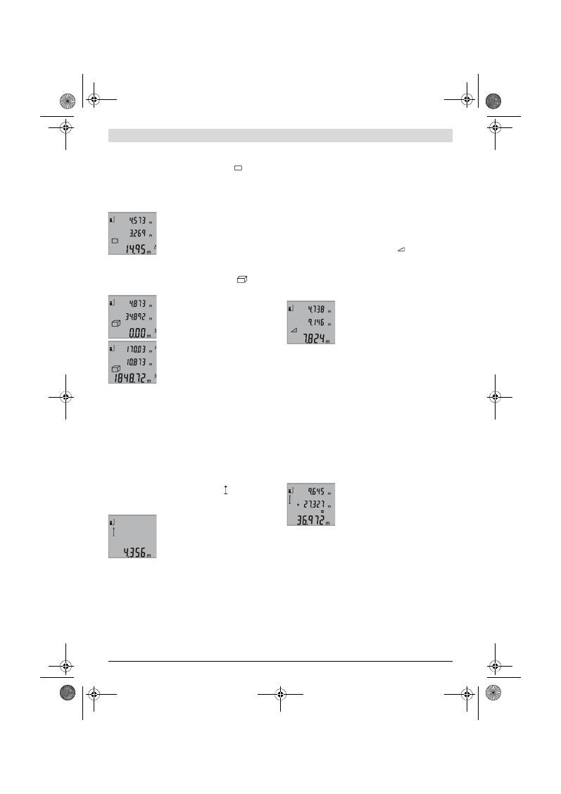
22
| Français
2 609 140 773 | (4.12.12)
Bosch Power Tools
Mesure des surfaces (voir figure C)
Pour les mesures de surfaces, appuyez sur la touche
3
jusqu’à
ce que l’affichage pour les mesures de surfaces
apparaisse
sur l’écran.
Puis mesurez successivement la longueur et la largeur tout
comme pour une mesure des longueurs. Le faisceau laser
reste allumé entre les deux mesures.
Une fois la deuxième mesure terminée, la
surface est automatiquement calculée et
affichée sur la ligne de résultat
b
. Les va-
leurs de mesure individuelles sont sur les
lignes de valeurs de mesure
a
.
Mesure des volumes (voir figure D)
Pour les mesures de volumes, appuyez sur la touche
3
jusqu’à
ce que l’affichage pour les mesures de volumes
appa-
raisse sur l’écran.
Puis mesurez successivement la lon-
gueur, la largeur et la hauteur tout comme
pour une mesure des longueurs. Le fais-
ceau laser reste allumé entre les trois me-
sures.
Une fois la troisième mesure terminée, le
volume est automatiquement calculé et
affiché sur la ligne de résultat
b
. Les va-
leurs de mesure individuelles sont sur les
lignes de valeurs de mesure
a
.
Il n’est pas possible d’afficher des valeurs supérieures à
999999 m
3
,
« ERROR »
apparaît sur l’écran. Répartissez le
volume à mesurer en plusieurs mesures individuelles, calcu-
lez les valeurs séparément et ensuite additionnez-les.
Mesure continue (voir figure E)
En mesure continue, il est possible de déplacer l’appareil de
mesure par rapport à la cible, la valeur de mesure étant actua-
lisée toutes les 0,5 secondes env. L’utilisateur peut donc se
déplacer par exemple à partir d’un mur jusqu’à la distance
souhaitée, la distance actuelle est toujours lisible sur l’écran.
Pour les mesures continues, appuyez sur la touche
9
jusqu’à
ce que l’affichage pour la mesure continue apparaisse sur
l’écran. Pour déclencher la mesure, appuyez sur la touche
Prise de mesure
2
.
La valeur de mesure actuelle est indiquée
sur la ligne de résultat
b
.
En appuyant sur la touche Mesurer
2
,
vous arrêtez la mesure continue. La der-
nière valeur de mesure est indiquée sur la
ligne de résultat
b
. Dès que l’on appuie de
nouveau sur la touche Mesurer
2
, la mesure continue redé-
marre.
La mesure continue s’arrête automatiquement au bout de 5
minutes. La dernière valeur de mesure reste indiquée sur la
ligne de résultat
b
.
Mesure indirecte de la hauteur / Mesure simple à l’aide de
Pythagore (voir figure F)
La mesure indirecte des hauteurs sert à déterminer les dis-
tances qui ne peuvent pas être mesurées directement à cause
d’un obstacle qui gênerait le trajet du faisceau laser ou au cas
où il n’y aurait pas de surface cible disponible comme surface
de réflexion. On n’obtient des résultats corrects que si l’on
respecte exactement les angles droits requis pour la mesure
respective (théorème de Pythagore).
Veillez à ce que le point de référence de la mesure (par ex.
bord arrière de l’appareil de mesure) se trouve exactement au
même endroit pour toutes les mesures individuelles d’une
opération de mesure.
Le faisceau laser reste allumé entre les mesures individuelles.
Appuyez plusieurs fois sur la touche
3
jusqu’à ce que l’affi-
chage de la mesure de Pythagore simple
apparaisse sur
l’écran.
Comme pour une mesure de longueurs, mesurez les distances
« 1 »
et
« 2 »
dans cet ordre. Veillez à ce que vous ayez un
angle droit entre la distance
« 1 »
et la distance
« X »
recher-
chée.
Une fois la dernière mesure effectuée, le
résultat de la distance recherchée
« X »
s’affiche sur la ligne de résultat
b
. Les va-
leurs de mesure individuelles sont sur les
lignes de valeurs de mesure
a
.
Effacement des valeurs de mesure
En appuyant brièvement sur la touche
4
, il est possible d’effa-
cer dans toutes les fonctions de mesure la dernière valeur in-
dividuelle déterminée. En appuyant plusieurs fois brièvement
sur la touche, les valeurs individuelles déterminées sont effa-
cées dans l’ordre inverse.
Additionner des valeurs de mesure
Effectuez d’abord une mesure quelconque pour additionner
des valeurs de mesure. Ensuite, appuyez sur la touche Plus
8
.
Pour confirmer,
« + »
apparaît sur l’écran.
Pour additionner des volumes ou des surfaces, appuyez sur la
touche Plus
8
après avoir effectué la première opération de
mesure. Pour confirmer,
« + »
apparaît sur l’écran à gauche du
symbole des volumes/des surfaces.
Réalisez ensuite une deuxième opération de mesure.
Pour lire la somme des deux mesures, ap-
puyez à nouveau sur la touche Plus
8
. Le
calcul s’affiche sur les lignes des valeurs
de mesure
a
, la somme sur la ligne de ré-
sultat
b
.
Une fois la somme calculée, d’autres valeurs de mesure
peuvent être additionnées à ce résultat si l’on appuie sur la
touche Plus
8
avant de réaliser une mesure.
Notes pour l’addition :
– Il n’est pas possible d’additionner conjointement des va-
leurs de longueurs, de surfaces et de volumes. Si, par ex.,
l’on additionne une valeur de longueur et une valeur de sur-
face, et que l’on appuie sur la touche Plus
8
,
« ERROR »
ap-
paraît sur l’écran. L’appareil de mesure passe ensuite à la
dernière fonction de mesure active.
– C’est le résultat d’une mesure (p.ex. valeur de volume) qui
est à chaque fois additionné, pour les mesures continues
c’est la valeur de mesure affichée sur la ligne de résultat
b
.
OBJ_BUCH-1444-004.book Page 22 Tuesday, December 4, 2012 1:47 PM
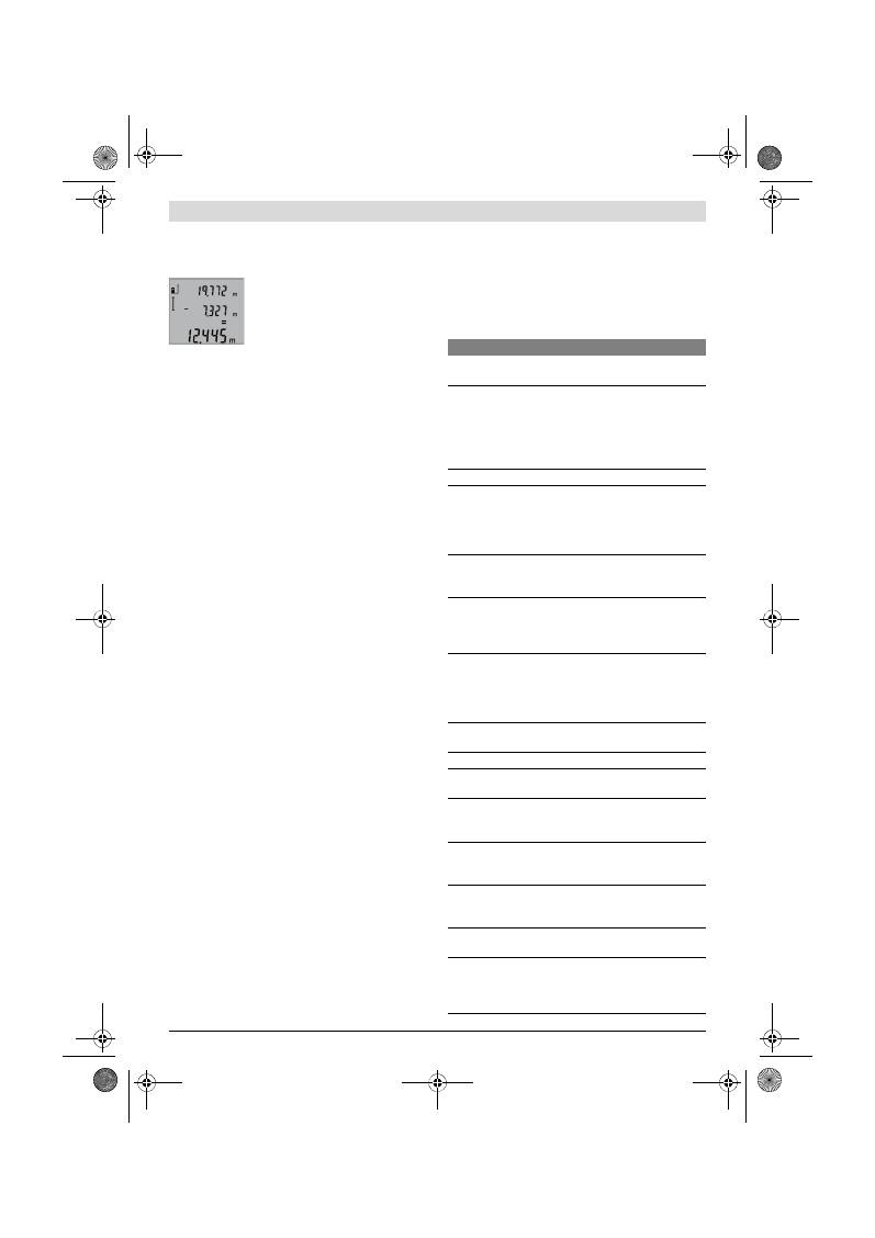
Français |
23
Bosch Power Tools
2 609 140 773 | (4.12.12)
Il n’est pas possible d’additionner des valeurs de mesure
individuelles des lignes de valeurs de mesure
a
.
Soustraction des valeurs de mesure
Pour soustraire des valeurs de mesure,
appuyez sur la touche
5
; pour confirmer,
« – »
apparaît sur l’écran. Le procédé sui-
vant est analogue à « Additionner des va-
leurs de mesure ».
Instructions d’utilisation
Indications générales
La cellule de réception
12
et la sortie du faisceau laser
11
ne
doivent pas être couvertes lors d’une mesure.
L’appareil de mesure ne doit pas être déplacé pendant une
mesure ( à l’exception de la fonction mesure continue). C’est
pourquoi il est recommandé de positionner l’appareil de me-
sure, si possible, sur une surface en butée.
Influences sur la plage de mesure
La plage de mesure dépend des conditions de luminosité et
des propriétés de réflexion de la surface cible. Pour obtenir
une meilleure visibilité du faisceau laser lors des travaux à
l’extérieur et en cas d’un fort ensoleillement, utilisez les lu-
nettes de vision du faisceau laser
19
(accessoire) et la mire de
visée
20
(accessoire) ou mettez à l’ombre la surface cible.
Influences sur le résultat de mesure
En raison de phénomènes physiques, il n’est pas exclu que les
mesures effectuées sur des surfaces différentes donnent des
résultats erronés. Ce sont par ex. :
– les surfaces transparentes (telles que verre, eau),
– les surfaces réfléchissantes (telles que métal, verre),
– les surfaces poreuses (telles que matériaux isolants),
– les surfaces à relief (telles que crépi, pierre naturelle).
Le cas échéant, utilisez la mire de visée laser
20
(accessoire)
pour ces surfaces.
Les mesures erronées sont également possibles sur les sur-
faces visées en biais.
Des couches d’air à températures différentes ou les réfléchis-
sements indirects peuvent également influencer la valeur de
mesure.
Contrôle de précision de la mesure des distances
La précision de la mesure des distances de l’appareil de me-
sure peut être contrôlée de la façon suivante :
– Choisissez une distance à mesurer invariable dans le
temps, d’une longueur de 1 m à 10 m environ dont la lon-
gueur vous est parfaitement connue (par ex. largeur d’une
pièce, largeur d’une porte). La distance à mesurer doit se
trouver à l’intérieur de la pièce, la surface cible de la me-
sure doit être lisse et bien réfléchissante.
– Mesurez cette distance 10 fois de suite.
L’écart des mesures individuelles de la valeur moyenne doit
être de ±2 mm au maximum. Consignez par écrit les mesures
pour pouvoir comparer la précision ultérieurement.
Travailler avec le trépied (accessoire)
L’utilisation d’un trépied est surtout nécessaire pour des dis-
tances plus importantes. Placez l’appareil de mesure avec le
filet 1/4"
14
sur la plaque à changement rapide du trépied
18
ou d’un trépied d’appareil photo disponible dans le com-
merce. Vissez-le au moyen de la vis de blocage de la plaque à
changement rapide.
En appuyant sur la touche
6
, réglez le niveau de référence
pour les mesures avec trépied (niveau de référence filetage).
Défaut
–
Causes et remèdes
Cause
Remède
Alerte de température (f) clignote, mesure n’est pas pos-
sible
L’appareil de mesure se trouve en
dehors de la plage de température
de fonctionnement située entre
– 10 °C et + 50 °C (dans le mode
de mesure continue jusqu’à
+ 40 °C).
Attendre jusqu’à ce que
l’appareil de mesure ait
atteint la température
de fonctionnement
Affichage « ERROR » sur l’écran
Addition/soustraction des valeurs
de mesure avec unités de mesure
différentes
N’additionnez/sous-
trayez que des valeurs
de mesure ayant les
mêmes unités de me-
sure
L’angle entre le faisceau laser et la
cible est trop aigu.
Augmentez l’angle entre
le faisceau laser et la
cible
La surface cible réfléchit trop for-
tement (par ex. miroir) ou trop fai-
blement (par ex. tissu noir), ou la
lumière ambiante est trop forte.
Utilisez la mire de visée
laser
20
(accessoire)
La sortie du faisceau laser
11
ou la
cellule de réception
12
sont cou-
vertes de rosée (par ex. à cause
d’un changement rapide de tem-
pérature).
A l’aide d’un chiffon
mou, essuyez et séchez
la sortie du faisceau la-
ser
11
ou la cellule de ré-
ception
12
La valeur calculée est supérieure à
999999 m/m
2
/m
3
.
Divisez les calculs en
étapes intermédiaires
Résultat de mesure invraisemblable
La surface cible ne réfléchit pas
précisément (par ex. eau, verre).
Couvrez la surface cible
La sortie du faisceau laser
11
ou la
cellule de réception
12
est cou-
verte.
Dégagez la sortie du fais-
ceau laser
11
ou la cel-
lule de réception
12
Le mauvais niveau de référence a
été réglé
Choisissez le niveau de
référence approprié
pour la mesure
Obstacle dans le tracé du faisceau
laser
Le point laser doit repo-
ser complètement sur la
surface cible.
L’affichage reste inchangé ou l’appareil de mesure réagit
de manière imprévue à une pression sur une touche
Erreur de logiciel
Retirez les piles et redé-
marrez l’appareil de me-
sure après les avoir re-
mises en place.
OBJ_BUCH-1444-004.book Page 23 Tuesday, December 4, 2012 1:47 PM
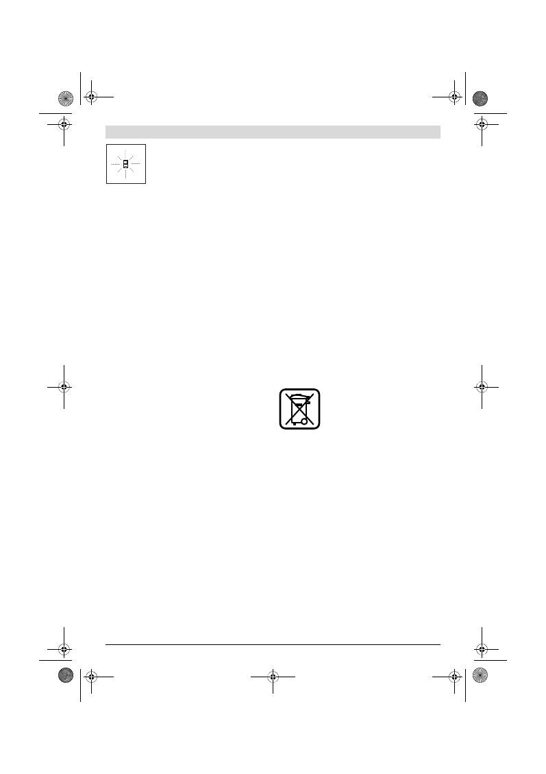
24
| Français
2 609 140 773 | (4.12.12)
Bosch Power Tools
L’appareil de mesure surveille la fonction
correcte lors de chaque mesure. Au cas où
un défaut serait constaté, seul le symbole
ci-contre clignote sur l’écran. Dans un tel
cas, ou quand les remèdes mentionnés
ci-haut ne permettent pas d’éliminer le dé-
faut, s’adresser au détaillant pour faire appel au Service
Après-Vente Bosch.
Entretien et Service Après-Vente
Nettoyage et entretien
Ne transportez et rangez l’appareil de mesure que dans son
étui de protection fourni avec l’appareil.
Maintenez l’appareil de mesure propre.
N’immergez jamais l’appareil de mesure dans l’eau ou dans
d’autres liquides.
Nettoyez l’appareil à l’aide d’un chiffon doux et humide. N’uti-
lisez pas de détergents ou de solvants.
Traitez notamment la cellule de réception
12
avec le même
soin avec lequel il faut traiter les lunettes ou la lentille d’un ap-
pareil photo.
Si, malgré tous les soins apportés à la fabrication et au
contrôle de l’appareil de mesure, celui-ci présentait un dé-
faut, la réparation ne doit être confiée qu’à une station de Ser-
vice Après-Vente agréée pour l’outillage Bosch. Ne démontez
pas l’appareil de mesure vous-même.
Pour toute demande de renseignement ou commande de
pièces de rechange, précisez-nous impérativement le numéro
d’article à dix chiffres de l’appareil de mesure indiqué sur la
plaque signalétique.
Au cas où l’appareil devrait être réparé, l’envoyer dans son
étui de protection
17
.
Service Après-Vente et Assistance
Notre Service Après-Vente répond à vos questions concer-
nant la réparation et l’entretien de votre produit et les pièces
de rechange. Vous trouverez des vues éclatées ainsi que des
informations concernant les pièces de rechange également
sous :
www.bosch-pt.com
Les conseillers techniques et assistants Bosch sont à votre
disposition pour répondre à vos questions concernant nos
produits et leurs accessoires.
France
Vous êtes un utilisateur, contactez :
Le Service Clientèle Bosch Outillage Electroportatif
Tel. : 0811 360122
(coût d’une communication locale)
Fax : (01) 49454767
E-Mail : contact.outillage-electroportatif@fr.bosch.com
Vous êtes un revendeur, contactez :
Robert Bosch (France) S.A.S.
Service Après-Vente Electroportatif
126, rue de Stalingrad
93705 DRANCY Cédex
Tel. : (01) 43119006
Fax : (01) 43119033
E-Mail : sav.outillage-electroportatif@fr.bosch.com
Belgique, Luxembourg
Tel. : +32 2 588 0589
Fax : +32 2 588 0595
E-Mail : outillage.gereedschap@be.bosch.com
Suisse
Tel. : (044) 8471512
Fax : (044) 8471552
E-Mail: Aftersales.Service@de.bosch.com
Autres pays
Pour avoir des renseignements concernant la garantie, les tra-
vaux d’entretien ou de réparation ou les pièces de rechange,
veuillez contacter votre détaillant spécialisé.
Elimination des déchets
Les appareils de mesure ainsi que leurs accessoires et embal-
lages, doivent pouvoir suivre chacun une voie de recyclage
appropriée.
Ne jetez pas les appareils de mesure et les accus/piles avec
les ordures ménagères !
Seulement pour les pays de l’Union Européenne :
Conformément à la directive européenne
2002/96/CE, les appareils de mesure dont
on ne peut plus se servir, et conformément
à la directive européenne 2006/66/CE, les
accus/piles usés ou défectueux doivent
être isolés et suivre une voie de recyclage
appropriée.
Les cellules de batterie rechargeables/piles dont on ne peut
plus se servir peuvent être déposées directement auprès de :
Suisse
Batrec AG
3752 Wimmis BE
Sous réserve de modifications.
OBJ_BUCH-1444-004.book Page 24 Tuesday, December 4, 2012 1:47 PM
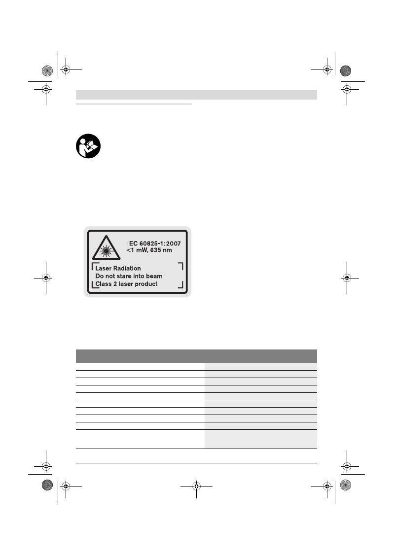
Español |
25
Bosch Power Tools
2 609 140 773 | (4.12.12)
Español
Instrucciones de seguridad
Deberán leerse íntegramente y respetarse
todas las instrucciones para poder trabajar
sin peligro y de forma segura con el apara-
to de medición. Jamás desvirtúe las seña-
les de advertencia del aparato de medi-
ción. GUARDE ESTAS INSTRUCCIONES EN
UN LUGAR SEGURO.
Atención: en caso de utilizar unos dispositivos de ma-
nejo y ajuste diferentes de los aquí indicados, o al se-
guir un procedimiento diferente, ello puede comportar
una exposición peligrosa a la radiación.
El aparato de medición se suministra de serie con una
señal de advertencia en inglés (en la ilustración del
aparato de medición, ésta corresponde a la
posición 15).
Antes de la primera puesta en marcha, pegue encima
de la señal de aviso en inglés la etiqueta adjunta redac-
tada en su idioma.
No oriente el rayo láser contra personas ni animales, ni
mire directamente hacia el rayo láser.
Este aparato de
medición genera radiación láser de la clase 2 según
IEC 60825-1. Esta radiación puede deslumbrar a las per-
sonas.
No use las gafas para láser como gafas de protección.
Las gafas para láser le ayudan a detectar mejor el rayo lá-
ser, pero no le protegen de la radiación láser.
No emplee las gafas para láser como gafas de sol ni pa-
ra circular.
Las gafas para láser no le protegen suficiente-
mente contra los rayos ultravioleta y además no le permi-
ten apreciar correctamente los colores.
Únicamente haga reparar su aparato de medición por
un profesional, empleando exclusivamente piezas de
repuesto originales.
Solamente así se mantiene la seguri-
dad del aparato de medición.
No deje que los niños puedan utilizar desatendidos el
aparato de medición por láser.
Podrían deslumbrar, sin
querer, a otras personas.
No utilice el aparato de medición en un entorno con pe-
ligro de explosión, en el que se encuentren combusti-
bles líquidos, gases o material en polvo.
El aparato de
medición puede producir chispas e inflamar los materiales
en polvo o vapores.
Descripción y prestaciones del pro-
ducto
Despliegue y mantenga abierta la solapa con la imagen del
aparato de medición mientras lee las instrucciones de mane-
jo.
Utilización reglamentaria
El aparato de medición ha sido proyectado para medir distan-
cias, longitudes, alturas, separaciones, y para calcular super-
ficies y volúmenes. El aparato de medición es adecuado para
medir tanto en interiores como en exteriores.
Datos técnicos
Telémetro digital por láser
GLM 50
Professional
Nº de artículo
3 601 K72 2..
Campo de medición
0,05 –50 m
A)
Precisión de medición (típica)
±1,5 mm
B)
Resolución
1 mm
Temperatura de operación
–10 °C...+50 °C
C)
Temperatura de almacenamiento
–20 °C...+70 °C
Humedad relativa máx.
90 %
Clase de láser
2
Tipo de láser
635 nm, <1 mW
Diámetro del rayo láser (a 25 °C), aprox.
– a una distancia de 10 m
– a una distancia de 50 m
6 mm
35 mm
OBJ_BUCH-1444-004.book Page 25 Tuesday, December 4, 2012 1:47 PM

26
| Español
2 609 140 773 | (4.12.12)
Bosch Power Tools
Componentes principales
La numeración de los componentes está referida a la imagen
del aparato de medición en la página ilustrada.
1
Display
2
Tecla de medición
3
Tecla para la medición de superficie, volumen y para la
medición de altura indirecta (Pitágoras)
4
Tecla de borrado / tecla de conexión/desconexión **
5
Tecla Menos
6
Selector del plano de referencia
7
Ojillo de sujeción del asa
8
Tecla Más
9
Tecla para la medición de longitud y medición permanente
10
Tapa del alojamiento de las pilas
11
Salida del rayo láser
12
Lente de recepción
13
Número de serie
14
Rosca de 1/4"
15
Señal de aviso láser
16
Enclavamiento de la tapa del alojamiento de las pilas
17
Estuche de protección
18
Trípode*
19
Gafas para láser*
20
Tablilla reflectante*
* Los accesorios descritos e ilustrados no corresponden al material
que se adjunta de serie.
** Mantener pulsada la tecla para acceder a las funciones ampliadas.
Elementos de indicación
a
Líneas de valores de medición
b
Línea de resultados
c
Funciones de medición
d
Láser conectado
e
Plano de referencia para la medición
f
Símbolo de temperatura
g
Símbolo de la pila
h
Indicación de fallo
“ERROR”
Montaje
Inserción y cambio de las pilas
Se recomienda utilizar pilas alcalinas de manganeso, o acu-
muladores, en el aparato de medición.
Con acumuladores de 1,2 V se pueden realizar menos medi-
ciones que con pilas de 1,5 V.
Para abrir la tapa del alojamiento de la pila
10
presione el en-
clavamiento
16
y retire la tapa. Inserte las pilas o los acumu-
ladores. Respete la polaridad indicada en la parte interior del
alojamiento de las pilas.
Automatismo de desconexión después de aprox.
– Láser
– Aparato de medición (sin medir)
20 s
5 min
Pilas
Acumuladores
2 x 1,5 V LR03 (AAA)
2 x 1,2 V HR03 (AAA)
Autonomía de la pila, aprox.
– Mediciones individuales
– Medición permanente
10000
D)
2,5 h
D)
Peso según EPTA-Procedure 01/2003
0,14 kg
Dimensiones
53 x 114 x 30 mm
Grado de protección
IP 54 (protección contra polvo y salpicaduras de agua)
Telémetro digital por láser
GLM 50
Professional
A) El alcance aumenta cuanto mejor sea reflejado el rayo láser por la superficie de incidencia (de forma dispersa y sin resplandecer) y cuanto mayor
sea el contraste del haz láser respecto a la luz ambiente (interiores, crepúsculo). En casos desfavorables (p.ej. al medir en exteriores con sol intenso)
puede que sea necesario utilizar la tablilla reflectante.
B) En mediciones a partir del canto posterior del aparato de medición. Bajo condiciones desfavorables como, p. ej., con sol intenso o si las superficies
son poco reflectantes, la desviación máxima es de
±
10 mm a una distancia de 50 m. Si las condiciones son favorables la desviación es de
±
0,05 mm/m.
C) En la función de medición permanente la temperatura de operación máx. es de +40
°C
.
D) Con acumuladores de 1,2 V pueden realizarse menos mediciones que con pilas de 1,5 V. La autonomía indicada para las pilas corresponde a medi-
ciones realizadas sin utilizar la iluminación del display.
El número de serie
13
grabado en la placa de características permite identificar de forma unívoca el aparato de medición.
Medición de longitud
Medición permanente
Medición de superficie
Medición de volumen
Medición sencilla con función Pitágoras
OBJ_BUCH-1444-004.book Page 26 Tuesday, December 4, 2012 1:47 PM
Español |
27
Bosch Power Tools
2 609 140 773 | (4.12.12)
Al insertar las pilas o acumuladores, respete la polaridad co-
rrecta mostrada en el alojamiento de las mismas.
En caso de aparecer el símbolo de la pila
por primera vez
en el display, es posible realizar todavía 100 mediciones indi-
viduales como mínimo. En este caso se desactiva la función
de medición permanente.
Si el símbolo de la pila
parpadea deberán cambiarse las pi-
las o acumuladores. En este caso no es posible realizar ningu-
na medición.
Siempre sustituya todas las pilas o acumuladores al mismo
tiempo. Solamente utilice pilas o acumuladores del mismo fa-
bricante e igual capacidad.
Saque las pilas o acumuladores del aparato de medi-
ción si pretende no utilizarlo durante largo tiempo.
Tras
un tiempo de almacenaje prolongado, las pilas y los acu-
muladores se pueden llegar a corroer o autodescargar.
Operación
Puesta en marcha
No deje desatendido el aparato de medición estando
conectado, y desconéctelo después de cada uso.
El rayo
láser podría llegar a deslumbrar a otras personas.
Proteja el aparato de medición de la humedad y de la
exposición directa al sol.
No exponga el aparato de medición ni a temperaturas
extremas ni a cambios bruscos de temperatura.
No lo
deje, p.ej., en el coche durante un largo tiempo. Si el apa-
rato de medición ha quedado sometido a un cambio fuerte
de temperatura, antes de ponerlo en servicio, esperar pri-
mero a que se atempere. Las temperaturas extremas o los
cambios bruscos de temperatura pueden afectar a la pre-
cisión del aparato de medición.
Evite los golpes fuertes o caídas del aparato de medi-
ción.
Si el aparato de medición ha sufrido un mal trato, an-
tes de continuar trabajando con él deberá realizarse una
comprobación de la precisión (ver “Comprobación de la
precisión en la medición de distancias”, página 29).
Conexión/desconexión
El aparato de medición puede
conectarse
de diversas for-
mas:
– Pulse la tecla de conexión/desconexión
4
: El aparato de
medición se conecta activándose automáticamente la fun-
ción de medición de longitud. El láser no es conectado.
– Pulse la tecla de medición
2
: Se conectan el aparato de me-
dición y el láser. En el aparato de medición se activa la fun-
ción de medición de longitud.
No oriente el rayo láser contra personas ni animales, ni
mire directamente hacia el rayo láser, incluso encon-
trándose a gran distancia.
Para
desconectar
el aparato pulse prolongadamente la tecla
de conexión/desconexión
4
.
Con el fin de proteger las pilas, el aparato de medición se des-
conecta automáticamente si no se pulsa ninguna tecla duran-
te aprox. 5 min.
Procedimiento de medición
Al conectar el aparato de medición pulsando la tecla de medi-
ción
2
se selecciona siempre automáticamente la función Me-
dición de longitud. Las demás funciones de medición pueden
ajustarse con la respectiva tecla selectora de función (ver
“Funciones de medición”, página 28).
Al conectar el aparato de medición, el canto posterior de éste
es seleccionado automáticamente como plano de referencia.
Pulsando la tecla Plano de referencia
6
puede Ud. modificar el
mismo (ver “Selección del plano de referencia”, página 27).
Apoye el aparato de medición, con el plano de referencia se-
leccionado, contra el punto inicial de medida deseado (p. ej.
una pared).
Pulse brevemente la tecla de medición
2
para conectar el rayo
láser.
No oriente el rayo láser contra personas ni animales, ni
mire directamente hacia el rayo láser, incluso encon-
trándose a gran distancia.
Oriente el rayo láser contra la superficie a medir. Para iniciar
la medición pulse de nuevo brevemente la tecla de medición
2
.
En el modo de medición permanente la medición comienza
nada más activar esta función.
El valor de medición se representa normalmente dentro de
0,5 s, y a más tardar, después de 4 s. La duración de la medi-
ción depende de la distancia, condiciones de luz y capacidad
reflectante de la superficie contra la cual incide el haz. Una
vez finalizada la medición, el rayo láser se desconecta auto-
máticamente.
Si tras dirigir el haz contra un punto no se realiza una medición
después de aprox. 20 s, el rayo láser se desconecta automá-
ticamente para proteger las pilas.
Selección del plano de referencia (ver figura A)
Para la medición puede Ud. elegir entre tres planos de refe-
rencia diferentes:
– el canto posterior del aparato de medición (p. ej. al asen-
tarlo contra una pared),
– el canto anterior del aparato de medición (p. ej. al medir
desde el canto de una mesa),
– el centro de la rosca
14
(p. ej., para mediciones con trípo-
de).
Pulse la tecla
6
tantas veces como sea necesario hasta que se
represente en el display el plano de referencia deseado.
Siempre que conecte el aparato de medición se preseleccio-
na automáticamente el plano de referencia del canto poste-
rior del mismo.
Iluminación del display
La iluminación del display se activa automáticamente según
las condiciones de luz reinantes. Si no se pulsa ninguna tecla
después de haber conectado la iluminación del display, la in-
tensidad de ésta es disminuida para proteger las pilas.
OBJ_BUCH-1444-004.book Page 27 Tuesday, December 4, 2012 1:47 PM
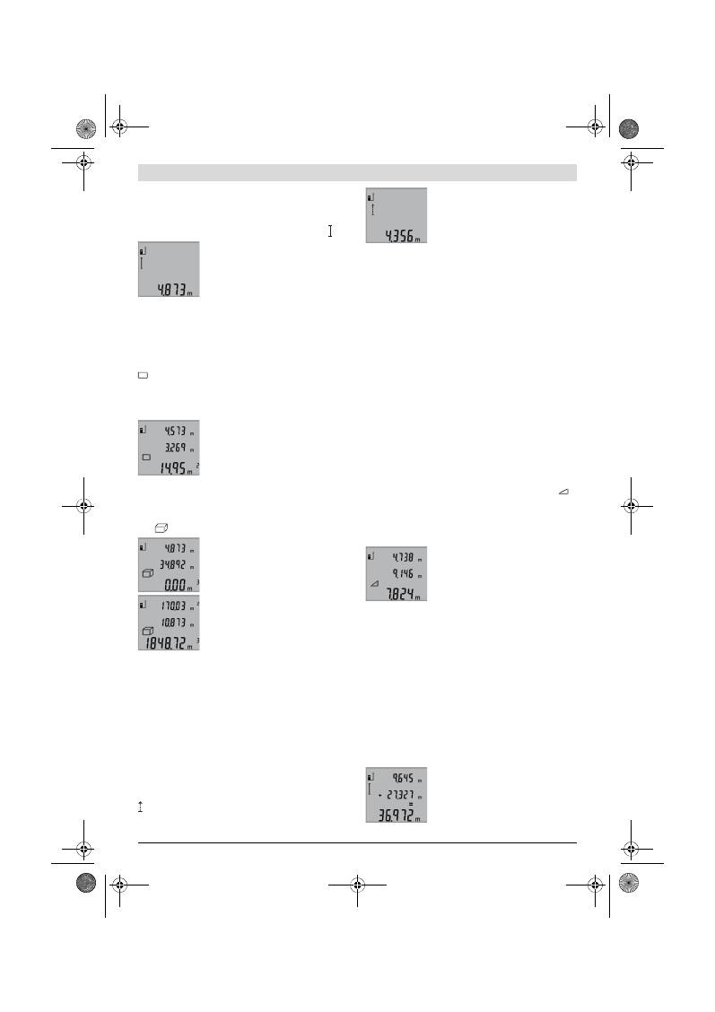
28
| Español
2 609 140 773 | (4.12.12)
Bosch Power Tools
Funciones de medición
Medición directa de la longitud (ver figura B)
Para medir longitudes vaya pulsando la tecla
9
hasta que en el
display aparezca el símbolo de medición de la longitud .
Para conectar el láser y para medir pulse
brevemente una vez en cada caso la tecla
de medición
2
.
El valor de medición se muestra en la línea
de resultados
b
.
Al realizar varias mediciones de longitud consecutivas los últi-
mos valores medidos se muestran en las líneas de valores de
medición
a
.
Medición de superficie (ver figura C)
Para medir superficies vaya pulsando la tecla
3
, hasta que
aparezca en el display el símbolo de medición de superficies
.
Seguidamente mida consecutivamente la longitud y la anchu-
ra procediendo igual que en la medición de longitud. Entre
ambas mediciones se mantiene encendido el rayo láser.
Al concluir la segunda medición se calcula
automáticamente la superficie, la cual se
representa en la línea de resultados
b
.
Los valores de medición individuales se
reflejan en las líneas de valores de medi-
ción
a
.
Medición de volumen (ver figura D)
Para medir volúmenes, vaya pulsando la tecla
3
hasta que
aparezca en el display el símbolo para la medición del volu-
men .
Seguidamente mida consecutivamente la
longitud, anchura y altura procediendo
igual que en la medición de longitud. En-
tre las tres mediciones se mantiene en-
cendido el rayo láser.
Al concluir la tercer medición se calcula
automáticamente el volumen, el cual se
representa en línea de resultados
b
. Los
valores de medición individuales se refle-
jan en las líneas de valores de medición
a
.
No es posible representar valores superiores a 999999 m
3
;
en el display se visualiza
“ERROR”
. En ese caso subdivida el
volumen a medir en volúmenes parciales, los cuales, una vez
medidos y calculados individualmente, Ud. podrá sumar al fi-
nal.
Medición permanente (ver figura E)
En la medición permanente es posible desplazar el aparato de
medición relativamente a un punto actualizándose el valor de
medición cada 0,5 s, aprox. Ud. puede irse separando de una
pared, p.ej., hasta alcanzar la separación deseada, siendo
posible determinar en cada momento la separación actual.
Para medir permanentemente pulse la tecla
9
hasta que en el
display aparezca la indicación para la medición permanente
. Pulse la tecla de medición
2
para iniciar la medición per-
manente.
El valor de medición actual se muestra en
la línea de resultados
b
.
Pulsando la tecla de medición
2
se finaliza
la medición permanente. El último valor
de medición se muestra en la línea de re-
sultados
b
. Pulsando nuevamente la tecla
de medición
2
se vuelve a activar la medición permanente.
La medición permanente se desactiva automáticamente des-
pués de 5 min. El último valor de medición puede seguirse vi-
sualizando en la línea de resultados
b
.
Medición indirecta de altura / Medición sencilla con fun-
ción Pitágoras (ver figura F)
La medición indirecta de altura se utiliza para determinar
aquellas distancias que no puedan medirse directamente por
encontrarse un obstáculo en la trayectoria del haz, o al no
existir una superficie de medición reflectante en el punto de
medición. Los resultados obtenidos solamente son correctos
si se mantienen exactamente los ángulos rectos precisados
en las respectivas mediciones (teorema de Pitágoras).
Cuide que el punto de referencia en la medición (p. ej., el can-
to posterior del aparato de medición) se encuentre exacta-
mente en la misma posición en todas las mediciones indivi-
duales precisadas para la medición.
Entre cada medición individual se mantiene encendido el rayo
láser.
Vaya pulsando la tecla
3
hasta que aparezca en el display el
símbolo para la medición sencilla con función Pitágoras
.
Proceda de igual manera que en una medición de longitud y
mida las distancias
“1”
y
“2”
, en ese orden. Preste atención a
que el tramo
“1”
y el tramo a determinar
“X”
formen un ángu-
lo recto.
Al concluir la última medición se muestra
el resultado del tramo
“X”
determinado
en la línea de resultados
b
. Los valores de
medición individuales se reflejan en las lí-
neas de valores de medición
a
.
Borrado de mediciones
Pulsando brevemente la tecla
4
puede Ud. borrar en todas las
funciones de medición el último valor medido. Pulsando bre-
vemente de forma seguida la tecla se van borrando en orden
inverso las mediciones individuales.
Suma de valores de medición
Para sumar valores de medición, realice primero una medi-
ción cualquiera. Pulse entonces la tecla Más
8
. En el display se
confirma esta acción con
“+”
.
Para sumar volúmenes o superficies, una vez finalizado el pri-
mer proceso de medición, pulse la tecla Más
8
. En el display
se confirma esta acción mostrándose
“+”
a la izquierda del
símbolo del volumen/superficie.
Realice entonces la segunda medición.
Para obtener la suma de ambas medicio-
nes pulse nuevamente la tecla Más
8
. El
cálculo aparece en las líneas de valores de
medición
a
y la suma en la línea de resul-
tados
b
.
OBJ_BUCH-1444-004.book Page 28 Tuesday, December 4, 2012 1:47 PM
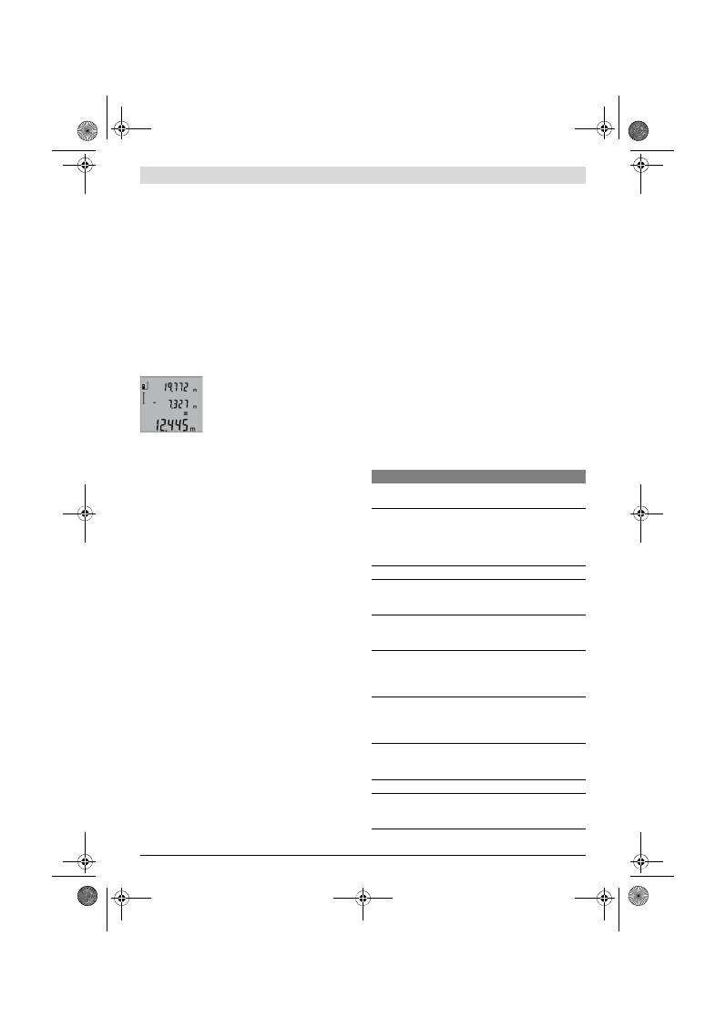
Español |
29
Bosch Power Tools
2 609 140 773 | (4.12.12)
Tras el cálculo de la suma pueden seguirse sumando a este re-
sultado otros valores de medición siempre que pulse la tecla
Más
8
antes de la medición.
Indicaciones referentes a la suma:
– No es posible combinar longitudes, superficies y volúme-
nes en la suma. Si se pretende sumar, p. ej., una longitud a
una superficie, al pulsar la tecla Más
8
aparece brevemen-
te
“ERROR”
en el display. Seguidamente, el aparato de
medición cambia a la última función de medición emplea-
da.
– En cada caso se suma el resultado de una medición (p.ej.
un volumen); en la medición permanente, el valor mostra-
do en la línea de resultados
b
. Los valores de medición in-
dividuales que aparecen en las líneas de valores de medi-
ción
a
no pueden sumarse.
Resta de mediciones
Para restar valores de medición pulse la
tecla Menos
5
, en el display se confirma
esta acción con
“–”
. La forma de proce-
der es similar a la “Suma de valores de
medición”.
Instrucciones para la operación
Indicaciones generales
La lente de recepción
12
y la salida del rayo láser
11
no deben
taparse durante la medición.
El aparato no deberá moverse al realizar la medición (excepto
en la función de medición permanente). Por ello, siempre que
sea posible, asiente o coloque el aparato de medición sobre
una superficie firme.
Influencias sobre el alcance
El alcance de la medición depende de las condiciones de luz y
de las propiedades de reflexión de la superficie de medición.
Al trabajar en exteriores y con sol intenso use las gafas para
láser
19
(accesorio opcional) y la tablilla láser reflectante
20
(accesorio opcional) para hacer más perceptible el haz del
láser, o bien, haga sombra a la superficie de medición.
Influencias sobre el resultado de medición
Debido a ciertos efectos físicos puede que se presenten me-
diciones erróneas al medir contra ciertas superficies. Perte-
necen a éstas:
– Superficies transparentes (p.ej. vidrio, agua),
– Superficies reflectantes (p.ej. metal pulido, vidrio),
– Superficies porosas (p.ej. materiales aislantes),
– Superficies estructuradas (p.ej. revoque rústico, piedra
natural).
Para estas superficies puede que sea necesario emplear la ta-
blilla reflectante
20
(accesorio opcional).
Las mediciones pueden ser erróneas también, si el rayo inci-
de inclinado contra la superficie.
Asimismo pueden afectar a la medición capas de aire de dife-
rente temperatura, o la recepción de reflexiones indirectas.
Comprobación de la precisión en la medición de distan-
cias
Ud. puede controlar la precisión en la medición de distancias
de la siguiente manera:
– Elija un tramo de medición de una longitud constante, en-
tre 1 a 10 m, aprox., (p. ej. la anchura de un cuarto, vano
de la puerta) cuya medida conozca Ud. con exactitud. La
medición deberá realizarse en el interior y deberá procu-
rarse que la superficie a medir sea lisa y que refleje bien.
– Mida esta distancia 10 veces seguidas.
La desviación de las mediciones individuales respecto al valor
medio deberá ser como máximo de ±2 mm. Registre estas
mediciones para poder comparar más tarde la precisión.
Operación con trípode (accesorio especial)
La utilización de un trípode es especialmente necesaria en
distancias más grandes. Puede fijar el aparato de medición
con la rosca de 1/4"
14
a la placa de cambio rápido del trípo-
de
18
, o a un trípode de tipo comercial. Fíjelo con el tornillo
de sujeción de la placa de cambio rápido.
Seleccione el plano de referencia para la medición con trípo-
de pulsando la tecla
6
(con la rosca como plano de referen-
cia).
Fallos
–
causas y soluciones
Causa
Solución
El símbolo de temperatura (f) parpadea y no es posible
medir
Temperatura de operación del
aparato de medición fuera del
campo de operación de – 10 °C a
+50 °C (en la función de medición
permanente hasta +40 °C).
Esperar a que el aparato
de medición haya alcan-
zado la temperatura de
operación
Indicación de “ERROR” en el display
Suma o resta de valores con unida-
des de medida diferentes
Solamente sumar o res-
tar valores con la misma
unidad de medida
Ángulo demasiado agudo entre el
rayo láser y el punto de medición.
Abrir el ángulo entre el
rayo láser y el punto de
medición
Reflexión excesiva de la superficie
de medición (p.ej. un espejo), de-
masiado débil (p.ej. tela negra), o
luz ambiente demasiado intensa.
Utilizar una tablilla láser
reflectante
20
(acceso-
rio especial)
Están empañadas la salida del rayo
láser
11
o la lente de recepción
12
(p.ej. por un cambio brusco de
temperatura).
Secar frotando con un
paño suave la salida del
rayo láser
11
o la lente
de recepción
12
El valor calculado es superior a
999999 m/m
2
/m
3
.
Subdividir el calculo en
varios pasos interme-
dios
El valor de medición no aparenta ser correcto
Reflexión indefinida de la superfi-
cie de medición (p.ej. agua, vi-
drio).
Cubrir la superficie de
medición
OBJ_BUCH-1444-004.book Page 29 Tuesday, December 4, 2012 1:47 PM
30
| Español
2 609 140 773 | (4.12.12)
Bosch Power Tools
El aparato de medición supervisa el correc-
to funcionamiento en cada medición. En ca-
so de detectarse un fallo solamente parpa-
dea en el display el símbolo mostrado al
margen. En este caso, o si las soluciones
arriba indicadas no ayudan a subsanar un
fallo, acuda a su comercio habitual el cual se encargará de en-
viar el aparato al servicio técnico Bosch.
Mantenimiento y servicio
Mantenimiento y limpieza
Solamente guarde y transporte el aparato de medición en el
estuche de protección adjunto.
Mantenga limpio siempre el aparato de medición.
No sumerja el aparato de medición en agua ni en otros líqui-
dos.
Limpiar el aparato con un paño húmedo y suave. No usar de-
tergentes ni disolventes.
Cuide especialmente la lente de recepción
12
con igual esme-
ro que unas gafas o una cámara fotográfica.
Si a pesar de los esmerados procesos de fabricación y con-
trol, el aparato de medición llegase a averiarse, la reparación
deberá encargarse a un taller de servicio autorizado para he-
rramientas eléctricas Bosch. No abra Ud. el aparato de medi-
ción.
Al realizar consultas o solicitar piezas de repuesto, es impres-
cindible indicar siempre el nº de artículo de 10 dígitos que fi-
gura en la placa de características del aparato de medición.
En caso de una reparación, envíe el aparato en el estuche de
protección
17
.
Servicio técnico y atención al cliente
El servicio técnico le asesorará en las consultas que pueda
Ud. tener sobre la reparación y mantenimiento de su produc-
to, así como sobre piezas de recambio. Los dibujos de despie-
ce e informaciones sobre las piezas de recambio los podrá ob-
tener también en internet bajo:
www.bosch-pt.com
Nuestro equipo de asesores técnicos le orientará gustosa-
mente en cuanto a la adquisición, aplicación y ajuste de los
productos y accesorios.
España
Robert Bosch Espana S.L.U.
Departamento de ventas Herramientas Eléctricas
C/Hermanos García Noblejas, 19
28037 Madrid
Tel. Asesoramiento al cliente: 902 531 53
Fax: 902 531554
Venezuela
Robert Bosch S.A.
Final Calle Vargas. Edf. Centro Berimer P.B.
Boleita Norte
Caracas 107
Tel.: (0212) 2074511
México
Robert Bosch S. de R.L. de C.V.
Circuito G. Gonzáles Camarena 333
Centro de Ciudad Santa Fe - 01210 - Mexico DF
Tel. Interior: (01) 800 6271286
Tel. D.F.: 52843062
E-Mail: arturo.fernandez@mx.bosch.com
Argentina
Robert Bosch Argentina S.A.
Av. Córdoba 5160
C1414BAW Ciudad Autónoma de Buenos Aires
Atención al Cliente
Tel.: (0810) 5552020
E-Mail: herramientas.bosch@ar.bosch.com
Perú
Robert Bosch S.A.C.
Av. Republica de Panama 4045
Buzón Postal Lima 34 (Surquillo) - Lima
Tel.: (01) 7061100
Chile
Robert Bosch S.A.
Calle San Eugênio, 40
Ñuñoa - Santiago
Buzón Postal 7750000
Tel.: (02) 5203100
E-Mail: emasa@emasa.cl
Eliminación
Recomendamos que los aparatos de medición, accesorios y
embalajes sean sometidos a un proceso de recuperación que
respete el medio ambiente.
¡No arroje los aparatos de medición, acumuladores o pilas a la
basura!
Salida del rayo láser
11
o lente de
recepción
12
cubiertas.
Destapar la salida del ra-
yo láser
11
o lente de re-
cepción
12
Plano de referencia ajustado, inco-
rrecto
Seleccionar un plano de
referencia apropiado a
la medición a realizar
Obstáculo en la trayectoria del ra-
yo láser
El haz del láser no debe-
rá incidir parcialmente
contra el punto a medir.
La indicación en pantalla no varía o el aparato de medi-
ción se comporta de forma inesperada al pulsar una tecla
Fallo del software
Saque las pilas y vuelva a
conectar el aparato de
medición una vez que las
haya vuelto a montar.
Causa
Solución
OBJ_BUCH-1444-004.book Page 30 Tuesday, December 4, 2012 1:47 PM
Português |
31
Bosch Power Tools
2 609 140 773 | (4.12.12)
Sólo para los países de la UE:
Los aparatos de medición inservibles, así
como los acumuladores/pilas defectuosos
o agotados deberán acumularse por sepa-
rado para ser sometidos a un reciclaje eco-
lógico tal como lo marcan las Directivas Eu-
ropeas 2002/96/CE y 2006/66/CE,
respectivamente.
Los acumuladores/pilas inservibles pueden entregarse direc-
tamente a:
España
Servicio Central de Bosch
Servilotec, S.L.
Polig. Ind. II, 27
Cabanillas del Campo
Tel.: +34 9 01 11 66 97
Reservado el derecho de modificación.
Português
Indicações de segurança
Ler e seguir todas as instruções, para po-
der trabalhar com o instrumento de medi-
ção sem riscos e de forma segura. Jamais
permita que as placas de advertência no
instrumento de medição se tornem irreco-
nhecíveis. GUARDE BEM ESTAS INSTRU-
ÇÕES.
Cuidado – se forem utilizados outros equipamentos de
comando ou de ajuste ou outros processos do que os
descritos aqui, poderão ocorrer graves explosões de
radiação.
O instrumento de medição é fornecido com uma placa
de advertência em idioma inglês (marcada com número
15 na figura do instrumento de medição que se encon-
tra na página de esquemas).
Antes da primeira colocação em funcionamento, deve-
rá colar o adesivo com o texto de advertência no seu
idioma nacional sobre a placa de advertência em idio-
ma inglês.
Não apontar o raio laser na direcção de pessoas ou ani-
mais e não olhar directamente para o raio laser.
Este
instrumento de medição produz raios laser da classe de la-
ser 2, conforme IEC 60825-1. Desta forma poderá cegar
outras pessoas.
Não utilizar óculos de visualização de raio laser como
óculos de protecção.
Óculos de visualização de raio laser
servem para reconhecer o raio laser com maior facilidade,
e portanto, não protegem contra radiação laser.
Não utilizar óculos de visualização de raio laser como
óculos de protecção, nem no trânsito rodoviário.
Ócu-
los de visualização de raio laser não oferecem uma comple-
ta protecção contra raios UV e reduzem a percepção de co-
res.
Só permita que o seu aparelho seja reparado por pesso-
al especializado e qualificado e só com peças de reposi-
ção originais.
Desta forma é assegurada a segurança do
instrumento de medição.
Não permita que crianças utilizem o instrumento de
medição a laser sem supervisão.
Poderá cegar outras
pessoas sem querer.
Não trabalhar com o instrumento de medição em área
com risco de explosão, na qual se encontrem líquidos,
gases ou pós inflamáveis.
No instrumento de medição
podem ser produzidas faíscas, que podem inflamar pós ou
vapores.
Descrição do produto e da potência
Abrir a página basculante contendo a apresentação do instru-
mento de medição, e deixar esta página aberta enquanto esti-
ver lendo a instrução de serviço.
Utilização conforme as disposições
Este instrumento de medição é destinado para medir distân-
cias, comprimentos, alturas, espaços e para calcular áreas e
volumes. O instrumento de medição é apropriado para medir
em interiores e exteriores.
OBJ_BUCH-1444-004.book Page 31 Tuesday, December 4, 2012 1:47 PM

32
| Português
2 609 140 773 | (4.12.12)
Bosch Power Tools
Dados técnicos
Componentes ilustrados
A numeração dos componentes ilustrados refere-se à apre-
sentação do instrumento de medição na página de esquemas.
1
Display
2
Tecla de medição
3
Tecla para medição de áreas, de volumes e para a medi-
ção indirecta de altura (Pitágoras)
4
Tecla para anulação / tecla de ligar-desligar **
5
Tecla –
6
Tecla para selecção do nível de referência
7
Fixação da alça de transporte
8
Tecla +
9
Tecla para a medição de comprimentos e para a medição
contínua
10
Tampa do compartimento da pilha
11
Saída do raio laser
12
Lente de recepção
13
Número de série
14
Rosca de 1/4"
15
Placa de advertência laser
16
Travamento da tampa do compartimento da pilha
17
Bolsa de protecção
18
Tripé*
19
Óculos para visualização de raio laser*
20
Placa-alvo para laser*
* Acessórios apresentados ou descritos não pertencem ao volume
de fornecimento.
** Manter a tecla premida para chamar as funções ampliadas.
Medidor de distâncias digital laser
GLM 50
Professional
N° do produto
3 601 K72 2..
Faixa de medição
0,05 –50 m
A)
Exactidão de medição (tipicamente)
±1,5 mm
B)
Mínima unidade de indicação
1 mm
Temperatura de funcionamento
–10 °C...+50 °C
C)
Temperatura de armazenamento
–20 °C...+70 °C
Máx. humidade relativa do ar
90 %
Classe de laser
2
Tipo de laser
635 nm, <1 mW
Diâmetro do raio laser (a 25 °C) aprox.
– a uma distância de 10 m
– a uma distância de 50 m
6 mm
35 mm
Desligamento automático após aprox.
– Laser
– Ferramenta de medição (sem medição)
20 s
5 min
Pilhas
Pilhas recarregáveis
2 x 1,5 V LR03 (AAA)
2 x 1,2 V HR03 (AAA)
Vida útil da pilha, aprox.
– Medições individuais
– Medição contínua
10000
D)
2,5 h
D)
Peso conforme EPTA-Procedure 01/2003
0,14 kg
Dimensões
53 x 114 x 30 mm
Tipo de protecção
IP 54 (protegido contra pó e salpicos de água)
A) O alcance aumenta, quanto melhor a luz do laser é reflectida pela superfície do alvo (dispersivo, no especular) e quanto mais claro o ponto de laser
for em relação à claridade ambiente (interiores, crepúsculo). Em condições desfavoráveis (p.ex. medir em exteriores com luz solar intensa) pode ser
necessária a utilização da placa alvo.
B) Em medições a partir do canto traseiro do instrumento de medição. No caso de condições desfavoráveis, como p. ex. forte incidência de sol ou su-
perfície de má reflexão, a divergência máxima é de
±
10 mm para 50 m. No caso de condições desfavoráveis deve ser calculado com uma influência
de
±
0,05 mm/m.
C) Na função de medição contínua a máx. temperatura de funcionamento é de +40
°C
.
D) Com células de acumuladores de 1,2 V é possível realizar menos medições do que com pilhas de 1,5 V. A indicada vida útil da pilha se refere a me-
dições sem iluminação do display.
O número de série
13
sobre a placa de características serve para a identificação inequívoca do seu instrumento de medição.
OBJ_BUCH-1444-004.book Page 32 Tuesday, December 4, 2012 1:47 PM

Português |
33
Bosch Power Tools
2 609 140 773 | (4.12.12)
Elementos de indicação
a
Linhas dos valores de medição
b
Linha de resultados
c
Funções de medição
d
Laser ligado
e
Nível de referência da medição
f
Monitorização da temperatura
g
Advertência da pilha
h
Indicação de erros
“ERROR”
Montagem
Introduzir/substituir pilhas
Para o funcionamento do instrumento de medição é recomen-
dável usar pilhas alcalinas de manganés ou acumuladores.
Com acumuladores de 1,2 V não é possível efecturar tantas
medições como com pilhas de 1,5 V.
Para abrir a tampa do compartimento da pilha
10
é necessá-
rio premir o travamento
16
e retirar a tampa do compartimen-
to. Colocar as pilhas ou os acumuladores. Observar a polari-
dade correcta de acordo com o lado interior do
compartimento das pilhas.
Colocar as pilhas ou os acumuladores no compartimento,
com a polaridade correcta, conforme o indicado na figura do
compartimento das pilhas.
Quando o símbolo da pilha
aparecer pela primeira vez no
display, ainda é possível efectuar no mínimo 100 medições
individuais. A função de medição contínua está desactivada.
Quando o símbolo da pilha
pisca, significa que as pilhas ou
as pilhas recarregáveis devem ser substituídas. Não é mais
possível executar medições.
Sempre substituir todas as pilhas ou os acumuladores ao
mesmo tempo. Só utilizar pilhas ou os acumuladores de um só
fabricante e com a mesma capacidade.
Retirar as pilhas ou os acumuladores do instrumento de
medição, se este não for utilizado por muito tempo.
As
pilhas e os acumuladores podem corroer-se ou descarre-
gar-se no caso de um armazenamento prolongado.
Funcionamento
Colocação em funcionamento
Não deixar o instrumento de medição ligado sem vigi-
lância e desligar o instrumento de medição após a utili-
zação.
Outras pessoas poderiam ser cegadas pelo raio la-
ser.
Proteger o instrumento de medição contra humidade
ou insolação directa.
Não sujeitar o instrumento de medição a temperaturas
extremas nem a oscilações de temperatura.
Não deixá-
lo p.ex. dentro de um automóvel durante muito tempo. No
caso de grandes variações de temperatura deverá deixar o
instrumento de medição alcançar a temperatura de funcio-
namento antes de colocá-lo em funcionamento. No caso
de temperaturas ou de oscilações de temperatura extre-
mas é possível que a precisão do instrumento de medição
seja prejudicada.
Evitar que instrumento de medição sofra fortes golpes
ou quedas.
Após fortes influências exteriores no instru-
mento de medição, deveria sempre ser realizado um con-
trolo de exactidão antes de continuar a trabalhar (ver
“Controle de exactidão da medição de distância”,
página 35).
Ligar e desligar
Para
ligar
o instrumento de medição, existem as seguintes
possibilidades:
– Premir a tecla de ligar-desligar
4
: O instrumento de medi-
ção é ligado e encontra-se na função de medição de com-
primentos. O laser não é ligado.
– Premir as teclas para medição
2
: o instrumento de medi-
ção e o laser são ligados. O instrumento de medição se en-
contra na função de medição de comprimento.
Não apontar o raio laser na direcção de pessoas nem de
animais, e não olhar no raio laser, nem mesmo de maio-
res distâncias.
Para
desligar
o instrumento de medição deverá premir pro-
longadamente a tecla de ligar-desligar
4
.
Se durante aprox. 5 min não for premida nenhuma tecla do
instrumento de medição, este desligar-se-á automaticamente
para poupar as pilhas.
Processo de medição
Depois de ligar premindo a tecla de medição
2
, o instrumento
de medição se encontra sempre na função de medição de
comprimento. Outras funções de medição podem ser ajusta-
das premindo a respectiva tecla de função (veja “Funções de
medição”, página 34).
Como superfície de referência para a medição, foi selecciona-
do, após a ligação, o canto traseiro do instrumento de medi-
ção. Premindo a tecla de nível de referência
6
é possível alte-
rar o nível de referência (veja “Seleccionar o nível de
referência”, página 34).
Posicionar o instrumento de medição, com o nível de referên-
cia seleccionado, no ponto de partida desejado para a medi-
ção (p. ex. parede).
Premir por instantes a tecla de medição
2
para ligar o raio la-
ser.
Não apontar o raio laser na direcção de pessoas nem de
animais, e não olhar no raio laser, nem mesmo de maio-
res distâncias.
Apontar o raio laser para a superfície alvo. Premir novamente
por instantes a tecla de medição
2
para iniciar a medição.
Medição de comprimento
Medição contínua
Medição de áreas
Medição de volume
Medição simples de pitágoras
OBJ_BUCH-1444-004.book Page 33 Tuesday, December 4, 2012 1:47 PM
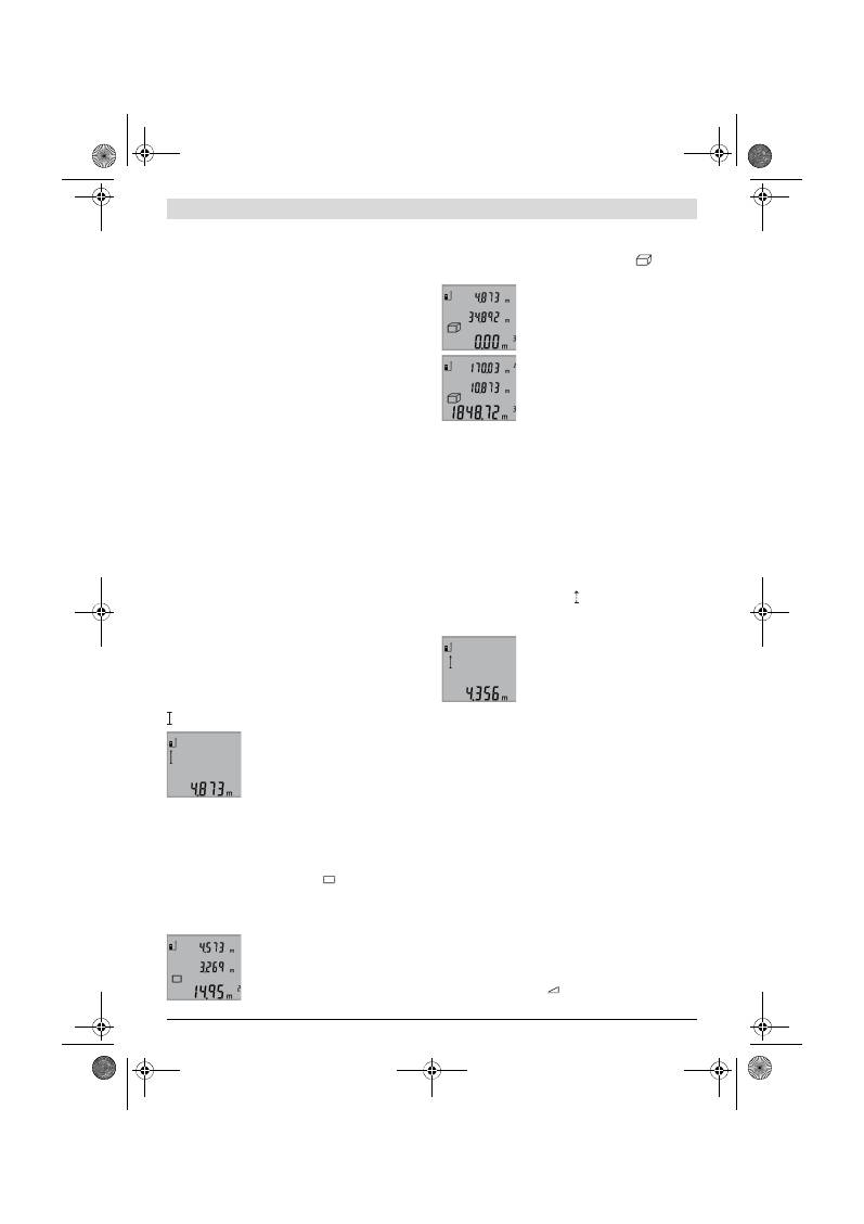
34
| Português
2 609 140 773 | (4.12.12)
Bosch Power Tools
Na função de medição contínua a medição começa imediata-
mente após a função ser ligada.
O valor de medição aparece normalmente dentro de 0,5 se-
gundos e o mais tardar após 4 segundos. A duração da medi-
ção depende da distância, das condições de iluminação e das
características de reflexão da superfície alvo. O raio laser é
desligado automaticamente após o final do processo de medi-
ção.
Se aprox. 20 s após visualizar, não ocorrer nenhuma medi-
ção, o raio laser desligar-se-á automaticamente para poupar
as pilhas.
Seleccionar o nível de referência (veja figura A)
Para a medição é possível seleccionar entre três diferentes ní-
veis de referência:
– o canto de trás do instrumento de medição (p. ex. para po-
sicionar o instrumento de medição de encontro com pare-
des),
– o canto da frente do instrumento de medição (p. ex. ao me-
dir a partir do canto de uma mesa),
– o centro da rosca
14
(p. ex. para medições com tripé).
Para seleccionar o nível de referência, deverá premir repeti-
damente a tecla
6
, até o nível de referência desejado aparecer
no display. Sempre que ligar o instrumento de medição, o
canto de trás é apresentado como nível de referência.
Iluminação do display
A iluminação do display é automaticamente activada de acor-
do com a claridade do ambiente. Se depois de ligar a ilumina-
ção do display não ocorrer uma pressão de tecla, esta será es-
curecida para poupar as pilhas.
Funções de medição
Simples medição de comprimento (veja figura B)
Para a medição de comprimento, deverá premir repetida-
mente a tecla
9
, até a indicação de medição de comprimento
aparecer no display.
Premir respectivamente uma vez por ins-
tantes a tecla de medição
2
para ligar o la-
ser e para medir.
O valor de medição é indicado na linha de
resultados
b
.
Se forem realizadas várias medições de comprimento, uma
após a outra, os resultados das últimas medições serão exibi-
dos nas linhas de valores de medição
a
.
Medição de áreas (veja figura C)
Para a medição de área, deverá premir repetidamente a tecla
3
, até a indicação de medição de área
aparecer no display.
Medir em seguida o comprimento e a largura, da mesma for-
ma como para uma medição de comprimento. O raio laser
permanece ligado entre as duas medições.
Após o final da segunda medição, a área é
calculada automaticamente e a linha de
resultados
b
é indicada. Os valores de
medição individuais encontram-se nas li-
nhas de medição
a
.
Medição do volume (veja figura D)
Para as medições de volume, deverá premir repetidamente a
tecla
3
, até a indicação de medição de volume
aparecer
no display.
Medir em seguida o comprimento, a lar-
gura, e a altura da mesma forma como pa-
ra uma medição de comprimento. O raio
laser permanece ligado entre as três me-
dições.
Após a terceira medição, o volume é auto-
maticamente calculado e indicado na li-
nha de resultados
b
. Os valores de medi-
ção individuais encontram-se nas linhas
de medição
a
.
Valores acima de 999999 m
3
não podem ser indicados; no
display aparece
“ERROR”
. Dividir o volume a ser medido em
medições individuais, calcular os valores separadamente e
em seguida somá-los.
Medição contínua (veja figura E)
No modo de medição contínua o instrumento de medição po-
de ser deslocado em relação ao alvo, sendo que o valor de me-
dição é actualizado a aprox. cada 0,5 segundos. É, por exem-
plo, possível distanciar-se de uma parede, até alcançar a
distância desejada, sendo que o instrumento indica continua-
mente a distância actual.
Para medições contínuas é necessário premir a tecla
9
até
aparecer no display a indicação para medição contínua. Pa-
ra iniciar a medição contínua é necessário premir a tecla me-
dir
2
.
O valor de medição actual é indicado na li-
nha de resultados
b
.
Premir a tecla de medição
2
para encerrar
a medição contínua. O último valor de me-
dição é indicado na linha de resultados
b
.
Premir novamente a tecla de medição
2
para reiniciar a medição contínua.
A medição contínua desliga-se automaticamente após
5 minutos. O último valor de medição permanece indicado na
linha de resultados
b
.
Medição de altura indirecta / Medição simples de pitágo-
ras (veja figura F)
A medição indirecta de altura serve para determinar distân-
cias, que não podem ser medidas directamente, porque um
obstáculo iria obstruir o caminho da luz ou porque não há su-
perfície reflectora à disposição. Resultados correctos só são
alcançados se os ângulos rectos exigidos para a respectiva
medição forem mantidos com exactidão (teorema de pitágo-
ras).
Observe que o ponto de referência da medição (p. ex. canto
de trás do instrumento de medição) permaneça exactamente
na mesma posição em todas as medições individuais de um
processo de medição.
O raio laser permanece ligado entre as medições individuais.
Premir repetidamente a tecla
3
até a indicação para a medi-
ção simples de pitágoras
aparecer no display.
OBJ_BUCH-1444-004.book Page 34 Tuesday, December 4, 2012 1:47 PM
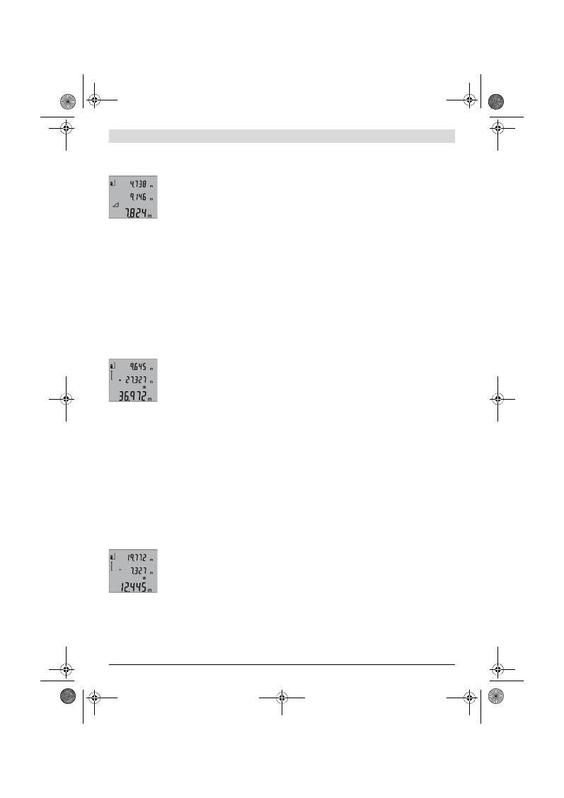
Português |
35
Bosch Power Tools
2 609 140 773 | (4.12.12)
Medir, como em uma medição de comprimento, os percursos
“1”
e
“2”
nesta sequência. Observe que entre o percurso
“1”
e o percurso procurado
“X”
haja um ângulo recto.
Após o final da última medição, o resulta-
do para o percurso procurado
“X”
é indi-
cado na linha de resultados
b
. Os valores
de medição individuais encontram-se nas
linhas de medição
a
.
Anular valores de medição
Premir por instantes a tecla
4
para anular, em todas as fun-
ções de medição, o último valor de medição individual averi-
guado. Premir repetidamente por instantes a tecla para anu-
lar, em sequência invertida, os valores individuais de
medição.
Somar valores de medição
Para adicionar valores de medição é primeiramente necessá-
rio realizar uma medição qualquer. Premir em seguida a tecla
+
8
. No display aparece, como confirmação,
“+”
.
Para adicionar volumes, ou áreas, é primeiramente necessá-
rio premir, após a conclusão do primeiro processo de medi-
ção, a tecla +
8
. No display aparece como confirmação
“+”
no
lado esquerdo do símbolo de volume e de área.
Agora deverá ser realizada uma segunda medição.
Para visualizar a soma de ambas as medi-
ções é necessário premir novamente a te-
cla +
8
. O cálculo é exibido nas linhas de
valores de medição
a
, a soma se encontra
na linha de resultados
b
.
Após o cálculo da soma, também é possível somar outros va-
lores de medição a este resultado, se a tecla +
8
for premida
antes da respectiva medição.
Notas sobre a adição:
– Valores de comprimento, de área e de volume não podem
ser misturados. Se, p. ex., forem adicionados um valor de
comprimento e um valor de área, aparece no display por
instantes
“ERROR”
ao premir a tecla +
8
. Em seguida o ins-
trumento de medição comuta para a função de medição
activa por último.
– É somado o respectivo resultado de uma medição (p.ex.
valor de volume), no caso de medições contínuas é soma-
do o valor de medição indicado na linha de resultados
b
.
Não é possível a adição dos valores de medição individuais
das linhas de valores de medição
a
.
Subtrair valores de medição
Para subtrair valores de medição, deverá
premir a tecla –
5
, no display aparece
“–”
como confirmação. O resto do proce-
dimento é igual a “Somar valores de medi-
ção”.
Indicações de trabalho
Indicações gerais
A lente de recepção
12
e a saída do raio laser
11
não devem
ser cobertas durante as medições.
O instrumento de medição não deve ser movimentado duran-
te uma medição (excepto na função de medição contínua).
Por este motivo se deve, se possível aplicar o instrumento de
medição a uma superfície de encosto ou de apoio firme.
Influências sobre a faixa de medição
A faixa de medição depende das condições de iluminação e
das características de reflexão da superfície alvo. Para melho-
rar a visibilidade do raio laser durante trabalhos ao ar livre ou
quando a luz do dia é intensa, deverá utilizar óculos para visu-
alização de raio laser
19
(acessório) e a placa alvo de laser
20
(acessório), ou sombrear a superfície alvo.
Influências sobre o resultado de medição
Devido a efeitos físicos não pode ser completamente excluído
que ocorram erros de medição ao medir sobre superfícies di-
ferentes. Estas podem ser:
– superfícies transparentes (p.ex. vidro, água),
– superfícies reflectoras (p.ex. metal polido, vidro),
– superfícies porosas (p.ex. materiais isolantes),
– superfícies com estruturas (p.ex. reboco áspero, pedra
natural).
Se necessário deverá utilizar a placa alvo de laser
20
(acessó-
rio) sobre estas superfícies.
Além disso é possível que ocorram erros de medição ao mirar
superfícies inclinadas.
O valor de medição também pode ser influenciado por cama-
das de ar com temperaturas diferentes ou reflexões indirec-
tas.
Controle de exactidão da medição de distância
A exactidão da medição de distância pode ser controlada da
seguinte maneira:
– Seleccionar uma secção de medição contínua inalterável
de aprox. 1 a 10 m de comprimento; o comprimento deve
ser precisamente conhecido (p. ex. a largura de um recin-
to, vão de uma porta). O percurso de medição deve estar
no interior do recinto, a superfície alvo da medição deve
ser lisa e de boa reflexão.
– Medir a distância 10 vezes em seguida.
A divergência entre as medições individuais e o valor médio
deve ser no máximo ±2 mm. Protocolar as medições, para
mais tarde poder comparar a precisão.
Trabalhar com o tripé (acessório)
A utilização de um tripé é especialmente necessária para
maiores distâncias. Colocar o instrumento de medição com a
rosca de 1/4"
14
sobre a placa de substituição rápido do tripé
18
ou sobre um tripé de fotografia de tipo comercial. Fixá-lo
com o parafuso de fixação da placa de substituição rápida.
Premir a tecla
6
para ajustar o nível de referência correspon-
dente para medições com tripé (nível de referência é a rosca).
OBJ_BUCH-1444-004.book Page 35 Tuesday, December 4, 2012 1:47 PM

36
| Português
2 609 140 773 | (4.12.12)
Bosch Power Tools
Avaria
–
Causas e acções correctivas
O instrumento de medição controla a fun-
ção correcta a cada medição. Se for verifi-
cado um defeito, só pisca no display o sím-
bolo apresentado ao lado. Neste caso, ou se
as acções correctivas não puderem elimi-
nar a avaria, o instrumento de medição de-
verá ser enviado, por meio do seu revendedor, a um serviço
pós-venda Bosch.
Manutenção e serviço
Manutenção e limpeza
Só armazenar e transportar o instrumento de medição na bol-
sa de protecção fornecida.
Manter o instrumento de medição sempre limpo.
Não mergulhar o instrumento de medição na água ou em ou-
tros líquidos.
Limpar sujidades com um pano húmido e macio. Não utilizar
produtos de limpeza nem solventes.
Tratar as lentes de recepção
12
com o mesmo cuidado, com
o qual é necessário tratar óculos ou as lentes de uma máquina
fotográfica.
Se o instrumento de medição falhar apesar de cuidadosos
processos de fabricação e de teste, a reparação deverá ser
executada por uma oficina de serviço autorizada para ferra-
mentas eléctricas Bosch. Não abrir pessoalmente o instru-
mento de medição.
Para todas as questões e encomendas de peças sobressalen-
tas é imprescindível indicar o número de produto de
10 dígitos como consta na placa de características do instru-
mento de medição.
Em caso de reparações, enviar o instrumento de medição
dentro da bolsa de protecção
17
.
Serviço pós-venda e consultoria de aplicação
O serviço pós-venda responde às suas perguntas a respeito
de serviços de reparação e de manutenção do seu produto,
assim como das peças sobressalentes. Desenhos explodidos
e informações sobre peças sobressalentes encontram-se em:
www.bosch-pt.com
A nossa equipa de consultoria de aplicação Bosch esclarecem
com prazer todas as suas dúvidas a respeito da compra, apli-
cação e ajuste dos produtos e acessórios.
Portugal
Robert Bosch LDA
Avenida Infante D. Henrique
Lotes 2E – 3E
1800 Lisboa
Tel.: 21 8500000
Fax: 21 8511096
Brasil
Robert Bosch Ltda.
Caixa postal 1195
13065-900 Campinas
Tel.: (0800) 7045446
www.bosch.com.br/contacto
Eliminação
Instrumentos de medição, acessórios e embalagens devem
ser enviados a uma reciclagem ecológica de matéria prima.
Não deitar os instrumentos de medição e acumuladores/pi-
lhas no lixo doméstico!
Causa
Solução
Advertência de temperatura (f) pisca; a medição não é
possível
O instrumento de medição encon-
tra-se além da temperatura de fun-
cionamento de – 10 °C a +50 °C
(na função de medição contínua,
até +40 °C).
Esperar até o instrumen-
to de medição alcançar a
temperatura de funcio-
namento
Indicação “ERROR” no display
Adição/subtracção de valores de
medição com diferentes unidades
de medição
Só adicionar/subtrair
valores de medição com
unidades de medição
idênticas
O ângulo entre o raio laser e o alvo
é muito agudo.
Aumentar o ângulo entro
o raio laser e o alvo
A reflexão da superfície alvo é mui-
to intensa (p.ex. espelho) ou mui-
to fraca (p.ex. tecido preto), ou a
luz ambiente é muito clara.
Utilizar a placa alvo laser
20
(acessório)
A saída do raio laser
11
ou a lente
de recepção
12
estão embaciadas
(p.ex. por rápida mudança de tem-
peratura).
Limpar a saída do raio la-
ser
11
ou a lente de re-
cepção
12
com um pano
macio e seco
O valor calculado é maior do que
999999 m/m
2
/m
3
.
Dividir o cálculo em pas-
sos intermediários
O resultado de medição não é plausível
A superfície alvo não reflecte cor-
rectamente (p.ex. água, vidro).
Cobrir a superfície alvo
A saída do raio laser
11
ou a lente
de recepção
12
estão cobertas.
Assegure-se de que a sa-
ída do raio laser
11
ou a
lente de recepção
12
não estejam cobertas
Foi ajustado um nível de referência
errado
Seleccionar um nível de
referência apropriado
para a medição
Obstáculo no caminho do raio la-
ser
O ponto de laser deve
estar deitado completa-
mente sobre a superfície
alvo.
A indicação permanece inalterada ou o instrumento de
medição reage de maneira inesperada ao premir uma te-
cla
Erro no software
Retirar as pilhas e ligar
novamente o instrumen-
to de medição após re-
colocá-las no aparelho.
OBJ_BUCH-1444-004.book Page 36 Tuesday, December 4, 2012 1:47 PM
Italiano |
37
Bosch Power Tools
2 609 140 773 | (4.12.12)
Apenas países da União Europeia:
Conforme as Directivas Europeias
2002/96/CE relativa aos resíduos de ins-
trumentos de medição europeias
2006/66/CE é necessário recolher separa-
damente os acumuladores/as pilhas defei-
tuosos ou gastos e conduzí-los a uma reci-
clagem ecológica.
Sob reserva de alterações.
Italiano
Norme di sicurezza
Tutte le istruzioni devono essere lette ed
osservate per lavorare con lo strumento di
misura senza pericoli ed in modo sicuro. In
nessun caso rendere irriconoscibili le tar-
ghette di avvertenza poste sullo strumento
di misura. CONSERVARE ACCURATAMEN-
TE LE PRESENTI ISTRUZIONI.
Attenzione – In caso di utilizzo di dispositivi di coman-
do o di regolazione di natura diversa da quelli riportati
in questa sede oppure qualora si seguano procedure di-
verse vi è il pericolo di provocare un’esposizione alle
radiazioni particolarmente pericolosa.
Lo strumento di misura viene fornito con una targhetta
di indicazione di pericolo in lingua inglese (contrasse-
gnata con il numero di riferimento 15 nell’illustrazione
grafica dello strumento di misura).
Prima della prima messa in funzione incollare l’etichet-
ta fornita in dotazione con il testo nella Vostra lingua
sopra al testo in inglese della targhetta di pericolo.
Non dirigere mai il raggio laser verso persone oppure
animali ed evitare di guardare direttamente il raggio la-
ser.
Questo strumento di misura genera un raggio laser
della classe laser 2 conforme alla norma IEC 60825-1. Vi è
dunque il pericolo di abbagliare altre persone.
Non utilizzare gli occhiali visori per raggio laser come
occhiali di protezione.
Gli occhiali visori per raggio laser
servono a visualizzare meglio il raggio laser e non hanno la
funzione di proteggere dalla radiazione laser.
Non utilizzare gli occhiali visori per raggio laser come
occhiali da sole e neppure alla guida di autoveicoli.
Gli
occhiali visori per raggio laser non sono in grado di offrire
una completa protezione dai raggi UV e riducono la perce-
zione delle variazioni cromatiche.
Far riparare lo strumento di misura da personale spe-
cializzato qualificato e solo con pezzi di ricambio origi-
nali.
In tale maniera potrà essere salvaguardata la sicurez-
za dello strumento di misura.
Non permettere a bambini di utilizzare lo strumento di
misura laser senza sorveglianza.
Vi è il pericolo che ab-
baglino involontariamente altre persone.
Evitare di impiegare lo strumento di misura in ambienti
soggetti al rischio di esplosioni e nei quali si trovino li-
quidi, gas oppure polveri infiammabili.
Nello strumento
di misura possono prodursi scintille che incendiano la pol-
vere o i vapori.
Descrizione del prodotto e caratteri-
stiche
Si prega di aprire il risvolto di copertina su cui si trova raffigu-
rato schematicamente lo strumento di misura e lasciarlo aper-
to mentre si legge il manuale delle Istruzioni per l’uso.
Uso conforme alle norme
Lo strumento di misura è idoneo per la misurazione di distan-
ze, di lunghezze, di altezze, di spazi ed anche per il calcolo di
superfici e volumi. Lo strumento di misura è adatto per effet-
tuare misurazioni in ambienti interni ed all’esterno.
Dati tecnici
Rilevatore di distanze digitale al laser
GLM 50
Professional
Codice prodotto
3 601 K72 2..
Campo di misurazione
0,05 –50 m
A)
Precisione di misura (media)
±1,5 mm
B)
Minima unità di visualizzazione
1 mm
Temperatura di esercizio
–10 °C...+50 °C
C)
Temperatura di magazzino
–20 °C...+70 °C
Umidità relativa dell’aria max.
90 %
OBJ_BUCH-1444-004.book Page 37 Tuesday, December 4, 2012 1:47 PM

38
| Italiano
2 609 140 773 | (4.12.12)
Bosch Power Tools
Componenti illustrati
La numerazione dei componenti si riferisce all’illustrazione
dello strumento di misura che si trova sulla pagina con la rap-
presentazione grafica.
1
Display
2
Tasto di misurazione
3
Tasto per misurazione di superfici, volumi e misurazione
indiretta di altezze (Pitagora)
4
Tasto di cancellazione / tasto di accensione e spegni-
mento **
5
Tasto meno
6
Tasto selezione del piano di riferimento
7
Aggancio cinturino per trasporto
8
Tasto più
9
Tasto di misurazione di lunghezze ed in continuo
10
Coperchio del vano batterie
11
Uscita radiazione laser
12
Lente di ricezione
13
Numero di serie
14
Attacco treppiede 1/4"
15
Targhetta di indicazione di pericolo del raggio laser
16
Bloccaggio del coperchio del vano batterie
17
Astuccio di protezione
18
Treppiede*
19
Occhiali per la visualizzazione del laser*
20
Pannello di puntamento per raggi laser*
* L’accessorio illustrato o descritto nelle istruzioni per l’uso non è
compreso nella fornitura standard.
** Tenere il tasto premuto per richiamare le funzioni ampliate.
Elementi di visualizzazione
a
Righe valori misurati
b
Riga risultato
c
Funzioni di misurazione
d
Laser attivato
e
Piano di riferimento della misurazione
f
Indicatore temperatura
g
Indicatore dello stato delle batterie
h
Indicatore di errore
«ERROR»
Classe laser
2
Tipo di laser
635 nm, <1 mW
Diametro raggio laser (con 25 °C) ca.
– a 10 m di distanza
– a 50 m di distanza
6 mm
35 mm
Disinserimento automatico dopo ca.
– Laser
– Strumento di misura (senza misurazione)
20 s
5 min
Batterie
Pile ricaricabili
2 x 1,5 V LR03 (AAA)
2 x 1,2 V HR03 (AAA)
Durata delle batterie ca.
– Misurazioni singole
– Misurazione continua
10000
D)
2,5 h
D)
Peso in funzione della EPTA-Procedure 01/2003
0,14 kg
Misure
53 x 114 x 30 mm
Tipo di protezione
IP 54 (protezione contro la polvere e contro gli spruzzi
dell’acqua)
Rilevatore di distanze digitale al laser
GLM 50
Professional
A) Il raggio di azione aumenta in modo direttamente proporzionale alla qualità con cui la luce laser viene riflessa dalla superficie del punto di puntamen-
to (dispersivo, non riflettente) ed alla luminosità del punto laser rispetto alla luminosità ambientale (locali interni, crepuscolo). In caso di condizioni
sfavorevoli (p.es. misurazioni in ambienti esterni con forti radiazioni solari) è possibile che sia necessario utilizzare un pannello di puntamento.
B) In caso di misurazioni dallo spigolo posteriore dello strumento di misura. In caso di condizioni sfavorevoli come p. es. forti radiazioni solari oppure
superfici che non riflettono bene, la divergenza massima è di
±
10 mm su 50 m. In caso di condizioni favorevoli si può contare su un influsso di
±
0,05 mm/m.
C) Nel funzionamento misurazione continua la max. temperatura di esercizio è di +40
°C
.
D) Con pile ricaricabili da 1,2 V è possibile effettuare meno misurazioni che con batterie da 1,5 V. La durata delle batterie indicata si riferisce a misu-
razioni senza illuminazione del display.
Per un’inequivocabile identificazione del Vostro strumento di misura fate riferimento al numero di serie
13
riportato sulla targhetta di costruzione.
Misurazione di lunghezze
Misurazione in continuo
Misurazione di superfici
Misurazione di volumi
Misurazione pitagorica semplice
OBJ_BUCH-1444-004.book Page 38 Tuesday, December 4, 2012 1:47 PM
Italiano |
39
Bosch Power Tools
2 609 140 773 | (4.12.12)
Montaggio
Applicazione/sostituzione delle batterie
Per il funzionamento dello strumento di misura si consiglia
l’impiego di batterie alcaline al manganese oppure batterie ri-
caricabili.
Con batterie ricaricabili da 1,2 V è possibile effettuare meno
misurazioni che con batterie da 1,5 V.
Per aprire il coperchio del vano batterie
10
premere il bloc-
caggio
16
e rimuovere il coperchio del vano batterie. Inserire
le batterie oppure le batterie ricaricabili, facendo attenzione
alla corretta polarizzazione, conformemente all’illustrazione
riportata sul lato interno del vano batterie.
Durante l’inserimento delle batterie o delle batterie ricaricabi-
li prestare attenzione alla corretta polarizzazione, conforme-
mente all’illustrazione nel vano batterie.
Dal momento in cui il simbolo della batteria
compare per la
prima volta sul display, sono possibili ancora almeno 100 mi-
surazioni singole. La funzione misurazione in continuo è disat-
tivata.
Se il simbolo della batteria
lampeggia, le batterie oppure le
pile ricaricabili devono essere sostituite, le misurazioni non
sono più possibili.
Sostituire sempre contemporaneamente tutte le batterie op-
pure le batterie ricaricabili. Utilizzare esclusivamente batterie
oppure batterie ricaricabili dello stesso produttore e con la
stessa capacità.
In caso di non utilizzo per lunghi periodi, estrarre le bat-
terie oppure le batterie ricaricabili dallo strumento di
misura.
In caso di lunghi periodi di deposito, le batterie e
le batterie ricaricabili possono subire corrosioni e scaricar-
si.
Uso
Messa in funzione
Non lasciare mai lo strumento di misura senza custodia
quando è acceso ed avere cura di spegnere lo strumen-
to di misura subito dopo l’utilizzo.
Vi è il pericolo che al-
tre persone potrebbero essere abbagliate dal raggio laser.
Proteggere lo strumento di misura da liquidi e
dall’esposizione diretta ai raggi solari.
Non esporre mai lo strumento di misura a temperature
oppure a sbalzi di temperatura estremi.
P.es. non la-
sciarlo per lungo tempo in macchina. In caso di elevati sbal-
zi di temperatura lasciare adattare alla temperatura am-
bientale lo strumento di misura prima di metterlo in
funzione. Temperature oppure sbalzi di temperatura estre-
mi possono pregiudicare la precisione dello strumento di
misura.
Evitare urti violenti oppure cadute dello strumento di
misura.
In caso che lo strumento di misura abbia subito
forti influssi esterni, prima di rimetterlo in funzione è ne-
cessario eseguire prima un controllo della precisione (vedi
«Controllo della precisione della misurazione delle distan-
ze», pagina 41).
Accensione/spegnimento
Per l’
accensione
dello strumento di misura vi sono le seguenti
possibilità:
– Premere il tasto di accensione e spegnimento
4
: lo stru-
mento di misura viene acceso e si trova nella funzione mi-
surazione di lunghezze. Il laser non viene inserito.
– Premere sul tasto di misurazione
2
: strumento di misura e
laser vengono accesi. Lo strumento di misura si trova nella
funzione misurazione di lunghezze.
Non dirigere mai il raggio laser su persone oppure su
animali ed evitare di guardare direttamente il raggio la-
ser anche da distanze maggiori.
Per lo
spegnimento
dello strumento di misura premere a lun-
go il tasto di accensione/spegnimento
4
.
Se per ca. 5 min non viene premuto alcun tasto sullo strumen-
to di misura, lo stesso si spegne poi automaticamente per pro-
teggere le batterie.
Operazione di misura
Dopo l’accensione, premendo il tasto di misurazione
2
lo stru-
mento di misura si trova sempre nella funzione misurazione di
lunghezze. Altre funzioni di misurazione possono essere rego-
late premendo il relativo tasto di funzione (vedi «Funzioni di
misurazione», pagina 40).
Dopo l’accensione il lato posteriore dello strumento di misura
è selezionato quale piano di riferimento per la misurazione.
Premendo il tasto piano di riferimento
6
è possibile modifica-
re il piano di riferimento (vedi «Selezione del piano di riferi-
mento», pagina 39).
Posizionare lo strumento di misura con il piano di riferimento
selezionato sul punto di partenza desiderato della misurazio-
ne (p. es. parete).
Per l’attivazione del raggio laser premere brevemente il tasto
di misurazione
2
.
Non dirigere mai il raggio laser su persone oppure su
animali ed evitare di guardare direttamente il raggio la-
ser anche da distanze maggiori.
Dirigere il raggio laser sulla superficie di puntamento. Per ef-
fettuare l’operazione di misurazione premere di nuovo breve-
mente il tasto di misurazione
2
.
Nella funzione misurazione in continuo la misurazione inizia
subito all’inserimento della funzione.
Il valore misurato appare normalmente entro 0,5 s ed al più
tardi dopo 4 s. La durata della misurazione dipende dalla di-
stanza, dalle condizioni di luminosità e dalle proprietà riflet-
tenti della superficie di puntamento. Una volta conclusa l’ope-
razione di misurazione, il raggio laser viene disinserito
automaticamente.
Se dopo ca. 20 s dopo la puntatura non si dovesse avere an-
cora nessuna misurazione, il raggio laser si disattiva automa-
ticamente riducendo il consumo delle batterie.
Selezione del piano di riferimento (vedi figura A)
Per la misurazione è possibile scegliere tra tre differenti piani
di riferimento:
– il bordo posteriore dello strumento di misura (p. es. in caso
di applicazione su pareti),
OBJ_BUCH-1444-004.book Page 39 Tuesday, December 4, 2012 1:47 PM
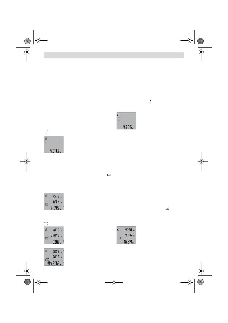
40
| Italiano
2 609 140 773 | (4.12.12)
Bosch Power Tools
– il bordo anteriore dello strumento di misura (p. es. in caso
di misurazione da un bordo del tavolo),
– il centro della filettatura
14
(p. es. per misurazioni con
treppiede).
Per la selezione del piano di riferimento premere il tasto
6
fino
a quando sul display viene visualizzato il piano di riferimento
desiderato. Dopo ogni accensione dello strumento di misura,
come piano di riferimento è preimpostato lo spigolo posterio-
re dello strumento di misura.
Illuminazione del display
L’illuminazione del display viene attivata automaticamente a
seconda della luminosità dell’ambiente. Se dopo l’accensione
dell’illuminazione del display non viene premuto alcun tasto,
la stessa viene ridotta per proteggere le batterie.
Funzioni di misurazione
Misurazione di lunghezze semplice (vedi figura B)
Per le misurazioni di lunghezze premere il tasto
9
fino a quan-
do sul display compare il simbolo per misurazione di lunghez-
ze .
Per l’attivazione del laser e per la misura-
zione premere brevemente una volta sul
tasto di misurazione
2
.
Il valore misurato viene visualizzato nella
riga risultato
b
.
In caso di diverse misurazioni di lunghezze una dietro l’altra, i
risultati delle ultime misurazioni vengono visualizzati nelle ri-
ghe valori misurati
a
.
Misurazione di superfici (vedi figura C)
Per le misurazioni di superfici premere il tasto
3
fino a quando
sul display compare il simbolo per misurazioni di superfici
.
Eseguire in un secondo tempo la misurazione della lunghezza
e della larghezza una dopo l’altra procedendo come nel caso
della misurazione di lunghezze. Il raggio laser resta attivato tra
le due operazioni di misurazione.
Al termine della seconda misurazione vie-
ne calcolata automaticamente la superfi-
cie e la stessa viene visualizzata nella riga
risultato
b
. I valori misurati singoli sono
indicati nelle righe valori misurati
a
.
Misurazione di volumi (vedi figura D)
Per le misurazioni di volumi premere il tasto
3
fino a quando
sul display compare l’indicazione per misurazione di volumi
.
Eseguire in un secondo tempo la misura-
zione della lunghezza, della larghezza e
dell’altezza una dopo l’altra procedendo
come nel caso della misurazione di lun-
ghezze. Il raggio laser resta attivato tra le
tre operazioni di misurazione.
Al termine della terza misurazione viene
calcolato automaticamente il volume e lo
stesso viene visualizzato nella riga risulta-
to
b
. I valori misurati singoli sono indicati
nelle righe valori misurati
a
.
Valori superiori a 999999 m
3
non possono essere visualizza-
ti, sul display compare
«ERROR»
. Ripartire il volume da misu-
rare in misurazioni singole i cui valori verranno poi calcolati
separatamente e quindi riuniti.
Misurazione in continuo (vedi figura E)
Durante la misurazione in continuo, lo strumento di misura
può essere mosso relativamente alla mira, per cui il valore mi-
surato viene attualizzato ca. ogni 0,5 s. È possibile ad esem-
pio allontanarsi da una parete fino alla distanza desiderata, la
distanza attuale è sempre leggibile.
Per le misurazioni in continuo premere il tasto
9
fino a quando
sul display compare il simbolo per misurazione in continuo.
Per avviare la misurazione in continuo premere il tasto di mi-
surazione
2
.
Il valore misurato attuale viene visualizza-
to nella riga risultato
b
.
Premendo il tasto di misurazione
2
termi-
na la misurazione in continuo. Il valore mi-
surato per ultimo viene visualizzato nella
riga risultato
b
. Premendo di nuovo il ta-
sto di misurazione
2
si riattiva la misurazione in continuo.
La misurazione in continuo si disinserisce automaticamente
dopo 5 min. Il valore misurato per ultimo rimane visualizzato
nella riga risultato
b
.
Misurazione indiretta di altezze / Misurazione pitagorica
semplice (vedi figura F)
La misurazione indiretta di altezze è prevista per il rilevamen-
to di distanze che non possono essere misurate direttamente
in quanto un ostacolo impedirebbe il passaggio del raggio op-
pure non vi è disposizione alcuna superficie di puntamento
con funzione riflettente. Risultati corretti vengono ottenuti
quindi solamente se gli angoli retti richiesti durante la rispet-
tiva misurazione vengono mantenuti esattamente (teorema di
Pitagora).
Prestare attenzione affinché il punto di riferimento della misu-
razione (p. es. bordo posteriore dello strumento di misura) ri-
manga esattamente nello stesso punto durante tutte le misu-
razioni singole all’interno di una procedura di misurazione.
Tra le misurazioni singole il raggio laser resta attivato.
Premere il tasto
3
fino a quando sul display compare l’indica-
zione per la misurazione pitagorica semplice
.
In caso di una misurazione di lunghezze misurare i tratti
«1»
e
«2»
in questa sequenza. Prestare attenzione affinché tra il
tratto
«1»
ed il tratto da individuare
«X»
sia presente un ango-
lo retto.
Al termine dell’ultima misurazione, il risul-
tato per il tratto da individuare
«X»
viene
visualizzato nella riga risultato
b
. I valori
misurati singoli sono indicati nelle righe
valori misurati
a
.
Cancellazione dei valori di misurazione
Premendo brevemente il tasto
4
è possibile cancellare in tutte
le funzioni di misurazione l’ultimo singolo valore di misura rile-
vato. Premendo ripetutamente brevemente il tasto vengono
cancellati i singoli valori misurati seguendo l’ordine inverso.
OBJ_BUCH-1444-004.book Page 40 Tuesday, December 4, 2012 1:47 PM
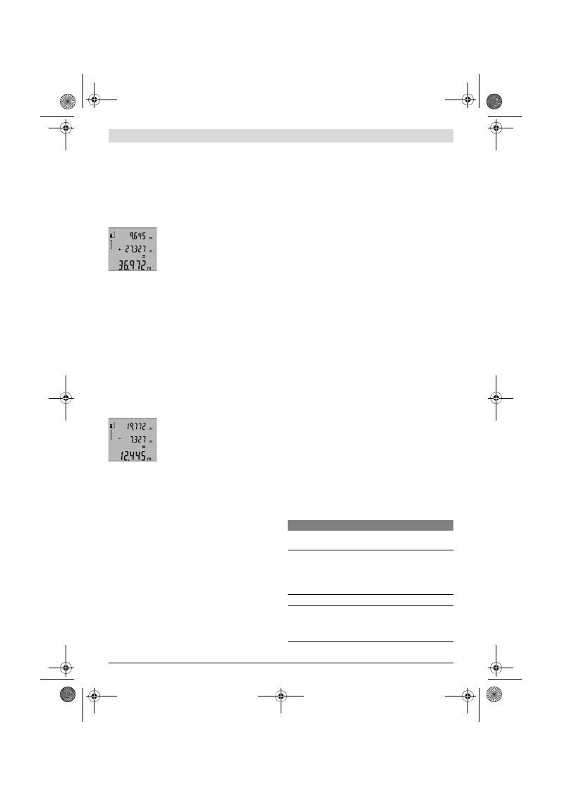
Italiano |
41
Bosch Power Tools
2 609 140 773 | (4.12.12)
Addizione valori misurati
Per addizionare valori misurati effettuare innanzitutto una mi-
surazione a scelta. Premere poi il tasto più
8
. Sul display com-
pare a conferma
«+»
.
Per addizionare volumi o superfici premere dopo la conclusio-
ne della prima operazione di misurazione il tasto più
8
. Sul di-
splay compare a conferma
«+»
a sinistra del simbolo volu-
mi/superfici.
Effettuare quindi una seconda misurazione.
Per richiedere la somma di entrambe le
misurazioni premere nuovamente il tasto
più
8
. Il calcolo viene visualizzato nelle ri-
ghe valori misurati
a
, la somma è riportata
nella riga risultato
b
.
Dopo il calcolo della somma a questo risultato possono essere
addizionati ulteriori valori misurati se prima della misurazione
viene premuto il tasto più
8
.
Indicazioni relative all’addizione:
– Valori di lunghezze, superfici e volumi non possono essere
addizionati mescolati. Se p. es. vengono addizionati un va-
lore lunghezza ed un valore superficie, premendo il tasto
più
8
compare brevemente
«ERROR»
sul display. Succes-
sivamente lo strumento di misura passa nell’ultima funzio-
ne di misura attiva.
– Viene addizionato sempre il risultato di una misurazione
(p.es. valore volume), nelle misurazioni in continuo il valo-
re misurato visualizzato nella riga risultato
b
. L’addizione di
valori misurati singoli dalle righe valori misurati
a
non è
possibile.
Sottrazione dei valori di misurazione
Per la sottrazione di valori misurati pre-
mere il tasto meno
5
, sul display compare
a conferma
«–»
. L’ulteriore modo di pro-
cedere è analogo a «Addizione valori mi-
surati».
Indicazioni operative
Indicazioni generali
Accertarsi che durante il corso di una misurazione non siano
coperte né la lente di ricezione
12
né l’uscita della radiazione
laser
11
.
Lo strumento di misura non deve essere mosso durante una
misurazione (ad eccezione della funzione misurazione in con-
tinuo). Per questa ragione appoggiare lo strumento di misura
possibilmente su una superficie di appoggio o di battuta soli-
da.
Influenze sul campo di misurazione
Il campo di misurazione dipende dalla condizioni di luce e dal-
le caratteristiche riflettenti della superficie di puntamento.
Per una migliore visibilità del raggio laser, in caso di lavori in
ambienti esterni ed in caso di forti radiazioni solari, utilizzare
gli occhiali per la visualizzazione del laser
19
(accessorio) ed
il pannello di puntamento per raggio laser
20
(accessorio) op-
pure oscurare la superficie di puntamento.
Influenze sul risultato di misurazione
Per gli effetti causati da leggi fisiche generali non si può esclu-
dere che misurando su differenti superfici possano verificarsi
errori di misurazione. Fanno parte di queste superfici:
– superfici trasparenti (p.es. vetro, acqua),
– superfici speculari (p.es. metallo lucido, vetro),
– superfici porose (p.es. materiali isolanti),
– superfici strutturate (p.es. intonaco grezzo, pietra natura-
le).
Utilizzare eventualmente su queste superfici il pannello di
puntamento per raggio laser
20
(accessorio).
Misurazioni errate sono inoltre possibili su superfici di mira
puntate obliquamente.
Allo stesso modo strati d’aria con temperature differenti op-
pure riflessi ricevuti indirettamente possono influenzare il va-
lore misurato.
Controllo della precisione della misurazione delle distan-
ze
È possibile controllare la precisione della misurazione delle
distanze procedendo come segue:
– Scegliere un tratto di misura stabilmente fisso con una lun-
ghezza di ca. 1 fino a 10 m e di cui si conosce esattamente
la lunghezza (p. es. larghezza di un locale, apertura di una
porta). Il tratto di misura deve essere in ambiente chiuso e
la superficie di puntamento della misurazione deve essere
liscia e ben riflettente.
– Misurare il tratto 10-volte consecutivamente.
La deviazione delle misurazioni singole dal valore medio può
essere al massimo di ±2 mm. Protocollare le misurazioni per
poter confrontare in un momento successivo la precisione.
Utilizzo del treppiede (accessori)
L’impiego di un treppiede è particolarmente necessario in ca-
so di grandi distanze. Posizionare lo strumento di misura con
il filetto da 1/4"
14
sulla piastra per il cambio rapido del trep-
piede
18
oppure di un treppiede per macchina fotografica co-
munemente in commercio. Avvitare saldamente con la vite di
fermo della piastra per cambio rapido.
Premendo il tasto
6
regolare rispettivamente il piano di riferi-
mento per misurazioni (piano di riferimento filetto).
Anomalie
–
cause e rimedi
Causa
Rimedi
Indicatore temperatura (f) lampeggia, misurazione non
possibile
Lo strumento di misura è al di fuori
della temperatura di esercizio da
– 10 °C fino a +50 °C (nel funzio-
namento misurazione continua fi-
no a +40 °C).
Attendere finché lo stru-
mento di misura avrà
raggiunto la temperatu-
ra di esercizio
Visualizzazione «ERROR» sul display
Addizione/sottrazione di valori di
misura rilevati con diverse unità di
misura
Sommare/sottrarre uni-
camente valori di misu-
razione rilevati con la
stessa unità di misura
OBJ_BUCH-1444-004.book Page 41 Tuesday, December 4, 2012 1:47 PM
42
| Italiano
2 609 140 773 | (4.12.12)
Bosch Power Tools
Lo strumento di misura controlla il corretto
funzionamento nel corso di ogni misurazio-
ne. In caso di riscontro di un’anomalia, sul
display lampeggia soltanto il simbolo visua-
lizzato accanto. In questo caso oppure
quando non dovesse essere possibile elimi-
nare un difetto ricorrendo alle misure riportate sopra, far per-
venire lo strumento di misura al Servizio Clienti Bosch attra-
verso il Vostro Rivenditore di fiducia.
Manutenzione ed assistenza
Manutenzione e pulizia
Conservare e trasportare lo strumento di misura utilizzando
esclusivamente l’astuccio di protezione fornito in dotazione.
Avere cura di tenere lo strumento di misura sempre pulito.
Non immergere mai lo strumento di misura in acqua oppure in
liquidi di altra natura.
Pulire ogni tipo di sporcizia utilizzando un panno umido e mor-
bido. Non utilizzare mai prodotti detergenti e neppure solven-
ti.
In modo particolare è necessario trattare la lente di ricezione
12
adoperando la stessa accuratezza con cui normalmente si
trattano occhiali oppure la lente di un apparecchio fotografi-
co.
Se nonostante gli accurati procedimenti di produzione e di
controllo lo strumento di misura dovesse guastarsi, la ripara-
zione deve essere effettuata da un punto di assistenza auto-
rizzato per gli elettroutensili Bosch. Non aprire da soli lo stru-
mento di misura.
Per ogni tipo di richiesta o di ordinazione di pezzi di ricambio,
è indispensabile comunicare sempre il codice prodotto a die-
ci cifre riportato sulla targhetta di fabbricazione dello stru-
mento di misura.
In caso si presentasse la necessità di riparazioni, spedire lo
strumento di misura mettendolo nell’apposito astuccio di pro-
tezione
17
.
Assistenza clienti e consulenza impieghi
Il servizio di assistenza risponde alle Vostre domande relative
alla riparazione ed alla manutenzione del Vostro prodotto
nonché concernenti le parti di ricambio. Disegni in vista
esplosa ed informazioni relative alle parti di ricambio sono
consultabili anche sul sito:
www.bosch-pt.com
Il team Bosch che si occupa della consulenza impieghi vi aiu-
terà in caso di domande relative ai nostri prodotti ed ai loro
accessori.
Italia
Officina Elettroutensili
Robert Bosch S.p.A.
Corso Europa, ang. Via Trieste 20
20020 LAINATE (MI)
Tel.: (02) 3696 2663
Fax: (02) 3696 2662
Fax: (02) 3696 8677
E-Mail: officina.elettroutensili@it.bosch.com
Svizzera
Tel.: (044) 8471513
Fax: (044) 8471553
E-Mail: Aftersales.Service@de.bosch.com
Smaltimento
Smaltire gli imballaggi, gli strumenti di misura e gli accessori
dismessi in modo che possano essere riciclati nel pieno ri-
spetto dell’ambiente.
Non gettare strumenti di misura e batterie ricaricabili/batterie
tra i rifiuti domestici!
L’angolo tra il raggio laser ed il pun-
to di mira è troppo acuto.
Aumentare l’angolo tra il
raggio laser ed il punto di
mira
Il riflesso della superficie di punta-
mento è troppo forte (p.es. spec-
chio) oppure troppo debole (p.es.
stoffa nera), oppure la luce am-
bientale è troppo forte.
Utilizzare il pannello di
puntamento laser
20
(accessorio opzionale)
L’uscita radiazione laser
11
oppu-
re la lente di ricezione
12
sono ap-
pannate (p.es. per un rapido sbal-
zo di temperatura).
Utilizzando una pezza
morbida asciugare la
lente di ricezione
11
op-
pure l’uscita radiazione
laser
12
Il valore calcolato è superore a
999999 m/m
2
/m
3
.
Ripartire il calcolo in
passaggi intermedi
Il risultato della misurazione non è plausibile
La superficie di puntamento non
riflette in modo inequivocabile
(p.es. acqua, vetro).
Coprire la superficie di
puntamento
L’uscita radiazione laser
11
oppu-
re la lente di ricezione
12
è coper-
ta.
Tenere libere l’uscita ra-
diazione laser
11
oppu-
re la lente di ricezione
12
Regolato piano di riferimento sba-
gliato
Selezionare piano di ri-
ferimento adatto alla mi-
surazione
Ostacolo sul percorso del raggio
laser
Il punto laser deve esse-
re posizionato comple-
tamente sulla superficie
di puntamento.
La visualizzazione rimane immutata oppure lo strumento
di misura reagisce in modo inatteso all’attivazione dei ta-
sti.
Errore nel software
Togliere le batterie e av-
viare di nuovo lo stru-
mento di misura dopo
averle inserite nuova-
mente.
Causa
Rimedi
OBJ_BUCH-1444-004.book Page 42 Tuesday, December 4, 2012 1:47 PM
Nederlands |
43
Bosch Power Tools
2 609 140 773 | (4.12.12)
Solo per i Paesi della CE:
Conformemente alla direttiva europea
2002/96/CE gli strumenti di misura diven-
tati inservibili e, in base alla direttiva euro-
pea 2006/66/CE, le batterie ricaricabili/
batterie difettose o consumate devono es-
sere raccolte separatamente ed essere in-
viate ad una riutilizzazione ecologica.
Pile ricaricabili/batterie inutilizzabili possono essere conse-
gnate direttamente presso:
Italia
Ecoelit
Viale Misurata 32
20146 Milano
Tel.: +39 02 / 4 23 68 63
Fax: +39 02 / 48 95 18 93
Svizzera
Batrec AG
3752 Wimmis BE
Con ogni riserva di modifiche tecniche.
Nederlands
Veiligheidsvoorschriften
Alle aanwijzingen moeten worden gelezen
en in acht worden genomen om zonder ge-
varen en veilig met het meetgereedschap
te werken. Maak waarschuwingsplaatjes
op het meetgereedschap nooit onleesbaar.
BEWAAR DEZE VOORSCHRIFTEN GOED.
Voorzichtig – wanneer andere dan de hier vermelde be-
dienings- en instelvoorzieningen worden gebruikt of
andere procedures worden uitgevoerd, kan dit tot ge-
vaarlijke stralingsblootstelling leiden.
Het meetgereedschap wordt geleverd met een waar-
schuwingsplaatje in het Engels (in de weergave van het
meetgereedschap op de pagina met afbeeldingen aan-
geduid met nummer 15).
Plak over de Engelse tekst van het waarschuwings-
plaatje de meegeleverde sticker in uw eigen taal voor-
dat u het gereedschap voor het eerst gebruikt.
Richt de laserstraal niet op personen of dieren en kijk
niet zelf in de laserstraal.
Dit meetgereedschap brengt
laserstraling van laserklasse 2 volgens IEC 60825-1 voort.
Daardoor kunt u personen verblinden.
Gebruik de laserbril niet als veiligheidsbril.
De laserbril
dient voor het beter herkennen van de laserstraal, maar
biedt geen bescherming tegen de laserstralen.
Gebruik de laserbril niet als zonnebril en niet in het ver-
keer.
De laserbril biedt geen volledige bescherming tegen
ultravioletstralen en vermindert de waarneming van kleu-
ren.
Laat het meetgereedschap repareren door gekwalifi-
ceerd, vakkundig personeel en alleen met originele
vervangingsonderdelen.
Daarmee wordt gewaarborgd
dat de veiligheid van het meetgereedschap in stand blijft.
Laat kinderen het lasermeetgereedschap niet zonder
toezicht gebruiken.
Anders kunnen personen worden
verblind.
Werk met het meetgereedschap niet in een omgeving
met explosiegevaar waarin zich brandbare vloeistof-
fen, brandbare gassen of brandbaar stof bevinden.
In
het meetgereedschap kunnen vonken ontstaan die het stof
of de dampen tot ontsteking brengen.
Product- en vermogensbeschrijving
Vouw de uitvouwbare pagina met de afbeelding van het meet-
gereedschap open en laat deze pagina opengevouwen terwijl
u de gebruiksaanwijzing leest.
Gebruik volgens bestemming
Het meetgereedschap is bestemd voor het meten van afstan-
den, lengten, hoogten en tussenruimten en voor het bereke-
nen van oppervlakten en inhouden. Het meetgereedschap is
geschikt voor metingen binnen- en buitenshuis.
OBJ_BUCH-1444-004.book Page 43 Tuesday, December 4, 2012 1:47 PM

44
| Nederlands
2 609 140 773 | (4.12.12)
Bosch Power Tools
Technische gegevens
Afgebeelde componenten
De componenten zijn genummerd zoals op de afbeelding van
het meetgereedschap op de pagina met afbeeldingen.
1
Display
2
Toets Meten
3
Toets voor oppervlakte-, inhouds- en indirecte hoogte-
meting (Pythagoras)
4
Verwijdertoets / aan/uit-toets **
5
Mintoets
6
Toets voor kiezen van referentievlak
7
Opname draagriem
8
Plustoets
9
Toets Lengte- en duurmeting
10
Deksel van batterijvak
11
Uitgang laserstraal
12
Ontvangstlens
13
Serienummer
14
1/4"-schroefdraad
15
Laser-waarschuwingsplaatje
16
Vergrendeling van het batterijvakdeksel
17
Beschermetui
18
Statief*
19
Laserbril*
20
Laserdoelpaneel*
* Niet elk afgebeeld en beschreven toebehoren wordt standaard
meegeleverd.
** Toets ingedrukt houden voor opvragen van uitgebreide functies.
Digitale laser-afstandsmeter
GLM 50
Professional
Zaaknummer
3 601 K72 2..
Meetbereik
0,05 –50 m
A)
Meetnauwkeurigheid (kenmerkend)
±1,5 mm
B)
Kleinste indicatie-eenheid
1 mm
Bedrijfstemperatuur
–10 °C...+50 °C
C)
Bewaartemperatuur
–20 °C...+70 °C
Relatieve luchtvochtigheid max.
90 %
Laserklasse
2
Lasertype
635 nm, <1 mW
Diameter laserstraal (bij 25 °C) ca.
– op 10 m afstand
– op 50 m afstand
6 mm
35 mm
Automatische uitschakeling na ca.
– laser
– meetgereedschap (zonder meting)
20 s
5 min
Batterijen
Accucellen
2 x 1,5 V LR03 (AAA)
2 x 1,2 V HR03 (AAA)
Levensduur batterij ca.
– afzonderlijke metingen
– duurmeting
10000
D)
2,5 h
D)
Gewicht volgens EPTA-Procedure 01/2003
0,14 kg
Afmetingen
53 x 114 x 30 mm
Beschermingsklasse
IP 54 (stof- en spatwaterbescherming)
A) De reikwijdte wordt groter naarmate het laserlicht beter door het oppervlak van het doel wordt gereflecteerd (gestrooid, niet gespiegeld) en naar-
mate de laserpunt lichter is dan de omgeving (interieurs, schemering). Bij ongunstige omstandigheden, zoals metingen buitenshuis met fel zonlicht,
kan gebruik van het doelpaneel nodig zijn.
B) Bij metingen vanaf achterzijde van meetgereedschap. Onder ongunstige omstandigheden, zoals fel zonlicht of een slecht reflecterend oppervlak,
bedraagt de maximale afwijking
±
10 mm op 50 m. Onder gunstige omstandigheden moet rekening worden gehouden met een invloed van
±
0,05 mm/m.
C) In de functie duurmeting bedraagt de max. bedrijfstemperatuur +40
°C
.
D) Met 1,2 V-accucellen zijn minder metingen mogelijk dan met 1,5 V-batterijen. De aangegeven batterijlevensduur heeft betrekking op metingen zon-
der displayverlichting.
Het serienummer
13
op het typeplaatje dient voor de eenduidige identificatie van uw meetgereedschap.
OBJ_BUCH-1444-004.book Page 44 Tuesday, December 4, 2012 1:47 PM

Nederlands |
45
Bosch Power Tools
2 609 140 773 | (4.12.12)
Indicatie-elementen
a
Meetwaarderegels
b
Resultaatregel
c
Meetfuncties
d
Laser ingeschakeld
e
Referentievlak van de meting
f
Temperatuurwaarschuwing
g
Batterijwaarschuwing
h
Foutindicatie
„ERROR”
Montage
Batterijen inzetten of vervangen
Voor het gebruik van het meetgereedschap worden alkali-
mangaanbatterijen of accu’s geadviseerd.
Met 1,2 V-accu’s zijn minder metingen mogelijk dan met
1,5 V-batterijen.
Als u het batterijvakdeksel
10
wilt openen, drukt u op de ver-
grendeling
16
en verwijdert u het batterijvakdeksel. Plaats de
batterijen of accu’s. Let daarbij op de juiste poolaansluitin-
gen, zoals aangegeven op de binnenzijde van het batterijvak.
Let bij het inzetten van de batterijen of accu’s op de juiste
poolaansluitingen overeenkomstig de afbeelding in het batte-
rijvak.
Als het batterijsymbool
voor het eerst in het display ver-
schijnt, zijn nog minstens 100 afzonderlijke metingen moge-
lijk. De functie duurmeting is gedeactiveerd.
Als het batterijsymbool
knippert, moet u de batterijen of
accucellen vervangen. Metingen zijn niet meer mogelijk.
Vervang altijd alle batterijen of accu’s tegelijkertijd. Gebruik
alleen batterijen of accu’s van één fabrikant en met dezelfde
capaciteit.
Neem de batterijen of accu’s uit het meetgereedschap
als u het langdurig niet gebruikt.
Als de batterijen of ac-
cu’s lang worden bewaard, kunnen deze gaan roesten en
leegraken.
Gebruik
Ingebruikneming
Laat het ingeschakelde meetgereedschap niet onbe-
heerd achter en schakel het meetgereedschap na ge-
bruik uit.
Andere personen kunnen door de laserstraal
verblind worden.
Bescherm het meetgereedschap tegen vocht en fel
zonlicht.
Stel het meetgereedschap niet bloot aan extreme tem-
peraturen of temperatuurschommelingen.
Laat het bij-
voorbeeld niet lange tijd in de auto liggen. Laat het meetge-
reedschap bij grote temperatuurschommelingen eerst op
de juiste temperatuur komen voordat u het in gebruik
neemt. Bij extreme temperaturen of temperatuurschom-
melingen kan de nauwkeurigheid van het meetgereed-
schap nadelig worden beïnvloed.
Voorkom heftige schokken of vallen van het meetge-
reedschap.
Na sterke externe inwerkingen op het meetge-
reedschap dient u, voordat u de werkzaamheden voortzet,
altijd een nauwkeurigheidscontrole uit te voeren (zie
„Nauwkeurigheidscontrole van de afstandsmeting”,
pagina 47).
In- en uitschakelen
Als u het meetgereedschap wilt
inschakelen
, heeft u de vol-
gende mogelijkheden:
– Druk op de aan/uit-toets
4
: Het meetgereedschap wordt
ingeschakeld en bevindt zich in de functie lengtemeting.
De laser wordt niet ingeschakeld.
– Indrukken van de meettoets
2
: meetgereedschap en laser
worden ingeschakeld. Het meetgereedschap bevindt zich
in de functie lengtemeting.
Richt de laserstraal niet op personen of dieren en kijk
zelf niet in de laserstraal, ook niet vanaf een grote af-
stand.
Als u het meetgereedschap wilt
uitschakelen
, drukt u lang op
de aan/uit-toets
4
.
Als er ca. 5 minuten geen toets op het meetgereedschap
wordt ingedrukt, wordt het meetgereedschap automatisch
uitgeschakeld om de batterijen te ontzien.
Meten
Na het inschakelen door het indrukken van de toets Meten
2
werkt het meetgereedschap altijd in de functie lengtemeting.
Andere meetfuncties kunt u instellen door op de bijbehoren-
de functietoets te drukken (zie „Meetfuncties”, pagina 46).
Als referentievlak voor de meting is na het inschakelen de ach-
terkant van het meetgereedschap gekozen. Door op de toets
Referentievlak
6
te drukken, kunt u het referentievlak wijzigen
(zie „Referentievlak kiezen”, pagina 46).
Plaats het meetgereedschap met het gekozen referentievlak
tegen het gewenste startpunt van de meting (bijv. tegen een
muur).
Druk voor het inschakelen van de laserstraal kort op de toets
Meten
2
.
Richt de laserstraal niet op personen of dieren en kijk
zelf niet in de laserstraal, ook niet vanaf een grote af-
stand.
Richt de laserstraal op het doeloppervlak. Druk opnieuw kort
op de toets meten
2
om de meting te starten.
In de functie duurmeting begint de meting onmiddellijk bij het
inschakelen van de functie.
De meetwaarde verschijnt meestal binnen 0,5 seconden en
uiterlijk na 4 seconden. De duur van de meting is afhankelijk
van de afstand, de lichtomstandigheden en de weerspiege-
Lengtemeting
Duurmeting
Oppervlaktemeting
Inhoudsmeting
Enkele Pythagorasmeting
OBJ_BUCH-1444-004.book Page 45 Tuesday, December 4, 2012 1:47 PM
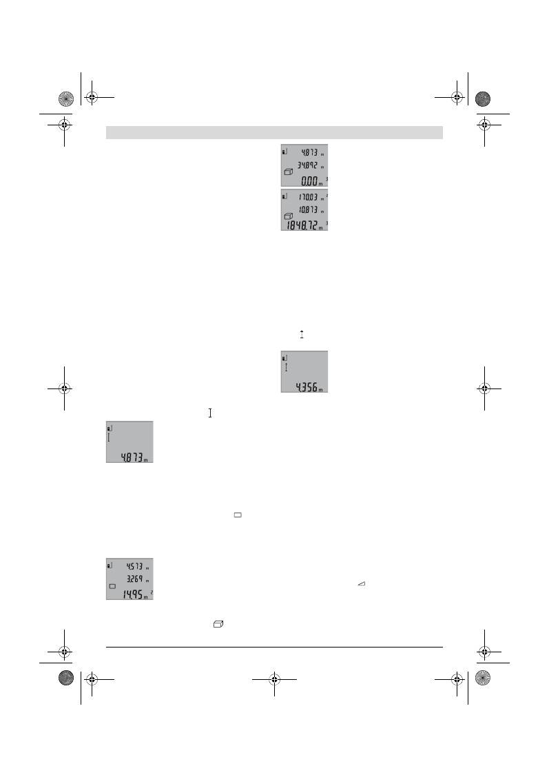
46
| Nederlands
2 609 140 773 | (4.12.12)
Bosch Power Tools
lingseigenschappen van het doeloppervlak. Na beëindiging
van de meting wordt de laserstraal automatisch uitgescha-
keld.
Als ca. 20 seconden na het richten geen meting plaatsvindt,
wordt de laserstraal automatisch uitgeschakeld om de batte-
rijen te sparen.
Referentievlak kiezen (zie afbeelding A)
Voor de meting kunt u uit drie verschillende referentievlakken
kiezen:
– de achterkant van het meetgereedschap (bijvoorbeeld als
het tegen een muur wordt geplaatst),
– vanaf de voorkant van het meetgereedschap (bijv. bij het
meten vanaf de rand van een tafel),
– vanaf het midden van de schroefdraad
14
(bijv. voor me-
tingen met statief).
Druk voor de keuze van het referentievlak zo vaak op de toets
6
tot in het display het gewenste referentievlak wordt weerge-
geven. Na het inschakelen van het meetgereedschap is altijd
de achterkant van het meetgereedschap als referentievlak
vooraf ingesteld.
Displayverlichting
De displayverlichting wordt afhankelijk van de lichtintensiteit
van de omgeving automatisch geactiveerd. Als na het inscha-
kelen van de displayverlichting geen toets wordt ingedrukt,
wordt de verlichting gedimd om de batterijen te ontzien.
Meetfuncties
Eenvoudige lengtemeting (zie afbeelding B)
Druk voor lengtemetingen zo vaak op de toets
9
totdat in het
display de indicatie voor lengtemeting verschijnt.
Druk voor het inschakelen van de laser en
voor het meten telkens eenmaal kort op
de toets meten
2
.
De meetwaarde wordt in de resultaatre-
gel
b
weergegeven.
Bij meer lengtemetingen achter elkaar worden de resultaten
van de laatste metingen in de meetwaarderegels
a
weergege-
ven.
Oppervlaktemeting (zie afbeelding C)
Druk voor oppervlaktemetingen zo vaak op de toets
3
tot in
het display de indicatie voor oppervlaktemeting
ver-
schijnt.
Meet vervolgens lengte en breedte na elkaar, net als bij een
lengtemeting. Tussen de beide metingen blijft de laserstraal
ingeschakeld.
Na afsluiting van de tweede meting wordt
de oppervlakte automatisch berekend en
in de resultaatregel
b
weergegeven. De
afzonderlijke meetwaarden staan in de
meetwaarderegels
a
.
Inhoudsmeting (zie afbeelding D)
Druk voor inhoudsmetingen zo vaak op de toets
3
tot in het
display de indicatie voor inhoudsmeting
verschijnt.
Meet vervolgens lengte, breedte en hoog-
te na elkaar, net als bij een lengtemeting.
Tussen de drie metingen blijft de laser-
straal ingeschakeld.
Na afsluiting van de derde meting wordt
de inhoud automatisch berekend en in de
resultaatregel
b
weergegeven. De afzon-
derlijke meetwaarden staan in de meet-
waarderegels
a
.
Waarden boven 999999 m
3
kunnen niet worden weergege-
ven. In het display verschijnt
„ERROR”
. Verdeel de te meten
inhoud in verschillende metingen, waarvan u de waarden
apart berekent en vervolgens optelt.
Duurmeting (zie afbeelding E)
Bij de duurmeting kan het meetgereedschap relatief ten op-
zichte van het doel worden verplaatst, waarbij de meetwaar-
de ongeveer elke 0,5 seconden wordt geactualiseerd. U kunt
zich zich bijvoorbeeld van een muur verwijderen tot aan de
gewenste afstand. De actuele afstand is steeds afleesbaar.
Druk voor duurmetingen op de toets
9
tot in het display de in-
dicatie voor duurmeting verschijnt. Druk voor het starten
van de duurmeting op de toets meten
2
.
De actuele meetwaarde wordt in de resul-
taatregel
b
weergegeven.
Door het indrukken van de toets meten
2
beëindigt u de duurmeting. De laatste
meetwaarde wordt in de resultaatregel
b
weergegeven. Als u opnieuw op de toets
meten
2
drukt, start de duurmeting opnieuw.
De duurmeting wordt na 5 minuten automatisch uitgescha-
keld. De laatste meetwaarde blijft in de resultaatregel
b
weer-
gegeven.
Indirecte hoogtemeting / Enkele Pythagorasmeting
(zie afbeelding F)
De indirecte hoogtemeting dient voor het bepalen van afstan-
den die niet rechtstreeks kunnen worden gemeten, omdat
een hindernis de laserstraal belemmert of omdat er geen doe-
loppervlak als reflector beschikbaar is. Correcte resultaten
worden alleen bereikt als de bij de meting vereiste rechte hoe-
ken nauwkeurig worden aangehouden (stelling van Pythago-
ras).
Let erop dat het referentiepunt van de meting (bijv. achter-
kant van meetgereedschap) bij alle afzonderlijke metingen
binnen één volledige meting op nauwkeurig op dezelfde
plaats blijft.
Tussen de afzonderlijke metingen blijft de laserstraal inge-
schakeld.
Druk zo vaak op de toets
3
tot in het display de indicatie voor
de enkele Pythagorasmeting
verschijnt.
Meet net als bij een lengtemeting de lijnstukken
„1”
en
„2”
in
deze volgorde. Let erop dat tussen lijnstuk
„1”
en het ge-
vraagde lijnstuk
„X”
een rechte hoek bestaat.
OBJ_BUCH-1444-004.book Page 46 Tuesday, December 4, 2012 1:47 PM
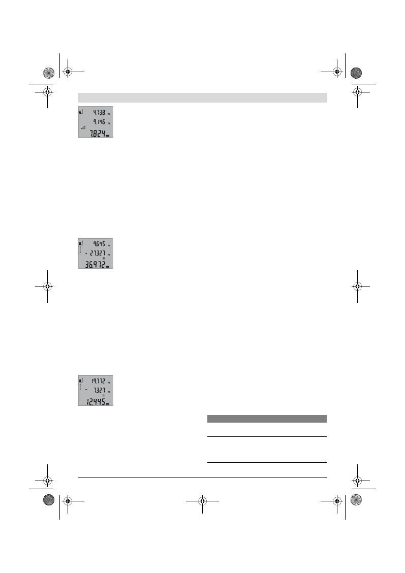
Nederlands |
47
Bosch Power Tools
2 609 140 773 | (4.12.12)
Na afsluiting van de laatste meting wordt
het resultaat voor het gevraagde lijnstuk
„X”
in de resultaatregel
b
weergegeven.
De afzonderlijke meetwaarden staan in
de meetwaarderegels
a
.
Meetwaarden verwijderen
Door het kort indrukken van de toets
4
kunt u in alle meetfunc-
ties de laatst gemeten afzonderlijke meetwaarde verwijde-
ren. Door het meermaals kort indrukken van de toets worden
de afzonderlijke meetwaarden in omgekeerde volgorde ver-
wijderd.
Meetwaarden optellen
Als u meetwaarden wilt optellen, voert u eerst een willekeuri-
ge meting uit. Druk vervolgens op de plustoets
8
. In het dis-
play verschijnt ter bevestiging
„+”
.
Als u inhouden of oppervlakten wilt optellen, drukt u na de
eerste afgesloten meting op de plustoets
8
. In het display ver-
schijnt ter bevestiging
„+”
links van het inhoud-/oppervlakte-
symbool.
Voer vervolgens een tweede meting uit.
Druk voor het opvragen van de som van
beide metingen nogmaals op de plustoets
8
. De berekening wordt in de meetwaar-
deregels
a
weergegeven. De som staat in
de resultaatregel
b
.
Na berekening van de som kunt u bij dit resultaat overige
meetwaarden optellen, als u vóór de meting telkens de plust-
oets
8
indrukt.
Opmerkingen over de optelling:
– Lengte-, oppervlakte- en inhoudswaarden kunnen niet bij
elkaar worden opgeteld. Als bijvoorbeeld een lengte- en
een oppervlaktewaarde worden opgeteld, verschijnt bij
het indrukken van de plustoets
8
kort
„ERROR”
in het dis-
play. Vervolgens keert het meetgereedschap terug naar de
meetfunctie die het laatst actief was.
– Er wordt telkens het resultaat van een meting (bijvoor-
beeld inhoudswaarde) opgeteld, bij duurmetingen de in de
resultaatregel
b
weergegeven meetwaarde. De optelling
van afzonderlijke meetwaarden uit de meetwaarderegels
a
is niet mogelijk.
Meetwaarden aftrekken
Als u meetwaarden wilt aftrekken, drukt u
op de mintoets
5
. In het display verschijnt
ter bevestiging
„–”
. Ga verder te werk als
bij „Meetwaarden optellen”.
Tips voor de werkzaamheden
Algemene aanwijzingen
De ontvangstlens
12
en de uitgang van de laserstraal
11
mo-
gen bij een meting niet afgedekt zijn.
Het meetgereedschap mag tijdens een meting niet bewogen
worden (met uitzondering van de functie duurmeting). Leg
daarom het meetgereedschap indien mogelijk tegen een vast
aanslag- of steunoppervlak.
Invloeden op het meetbereik
Het meetbereik is afhankelijk van de belichting en de mate
van weerspiegeling van het meetoppervlak. Gebruik voor een
betere zichtbaarheid van de laserstraal bij werkzaamheden
buitenshuis en bij fel zonlicht de laserbril
19
(toebehoren) en
het laserdoelpaneel
20
(toebehoren), of zorg voor schaduw
op het doelpaneel.
Invloeden op het meetresultaat
Vanwege bepaalde eigenschappen van materialen kunnen bij
metingen op sommige oppervlakken foutmetingen niet wor-
den uitgesloten. Daartoe behoren:
– transparante oppervlakken zoals glas en water,
– spiegelende oppervlakken zoals gepolijst metaal en glas,
– poreuze oppervlakken zoals isolatiemateriaal,
– oppervlakken met een structuur, zoals pleisterwerk en na-
tuursteen.
Gebruik indien nodig op deze oppervlakken het laserdoelpa-
neel
20
(toebehoren).
Foute metingen zijn bovendien mogelijk op doeloppervlakken
waarop schuin wordt gericht.
Ook kunnen luchtlagen met verschillende temperaturen of in-
direct ontvangen weerspiegelingen de meetwaarde beïnvloe-
den.
Nauwkeurigheidscontrole van de afstandsmeting
U kunt de nauwkeurigheid van de afstandmeting als volgt con-
troleren:
– Kies een onveranderlijke meetafstand met een lengte van
ca. 1 tot 10 meter waarvan u de lengte nauwkeurig kent
(bijv. kamerbreedte, deuropening). De meetafstand moet
binnenshuis liggen. Het doeloppervlak van de meting moet
glad en goed reflecterend zijn.
– Meet de afstand tien opeenvolgende keren.
De afwijking van de afzonderlijke metingen van de gemiddel-
de waarde mag maximaal ±2 mm bedragen. Houd de metin-
gen bij, zodat u de nauwkeurigheid op een later tijdstip kunt
vergelijken.
Werkzaamheden met het statief (toebehoren)
Het gebruik van een statief is vooral bij grotere afstanden
noodzakelijk. Zet het meetgereedschap met de 1/4"-schroef-
draad
14
op de snelwisselplaat van het statief
18
of een in de
handel verkrijgbaar fotostatief. Schroef het met de vastzet-
schroef van de snelwisselplaat vast.
Stel het referentievlak voor metingen met de aanslagstift door
het indrukken van de toets
6
overeenkomstig in (referentie-
vlak schroefdraad).
Oorzaken en oplossingen van fouten
Oorzaak
Oplossing
Temperatuurwaarschuwing (f) knippert, meting niet mo-
gelijk
Meetgereedschap buiten bedrijfs-
temperatuur van – 10 °C tot
+50 °C (in functie duurmeting tot
+40 °C).
Wacht tot het meetge-
reedschap bedrijfstem-
peratuur bereikt
OBJ_BUCH-1444-004.book Page 47 Tuesday, December 4, 2012 1:47 PM
48
| Nederlands
2 609 140 773 | (4.12.12)
Bosch Power Tools
Het meetgereedschap controleert de juiste
werking bij elke meting. Als een defect
wordt vastgesteld, knippert in het display
alleen nog het hiernaast staande symbool.
In dit geval of wanneer de fout niet met de
bovengenoemde maatregelen kan worden
verholpen, dient u het meetgereedschap via uw leverancier
naar de klantenservice van Bosch te sturen.
Onderhoud en service
Onderhoud en reiniging
Bewaar en transporteer het meetgereedschap alleen in het
meegeleverde beschermetui.
Houd het meetgereedschap altijd schoon.
Dompel het meetgereedschap niet in water of andere vloei-
stoffen.
Verwijder vuil met een vochtige, zachte doek. Gebruik geen
reinigings- of oplosmiddelen.
Verzorg in het bijzonder de ontvangstlens
12
met dezelfde
zorgvuldigheid waarmee een bril of een cameralens moeten
worden behandeld.
Mocht het meetgereedschap ondanks zorgvuldige fabricage-
en testmethoden toch defect raken, dient de reparatie te wor-
den uitgevoerd door een erkende klantenservice voor Bosch
elektrische gereedschappen. Open het meetgereedschap
niet.
Vermeld bij vragen en bestellingen van vervangingsonderde-
len altijd het uit tien cijfers bestaande zaaknummer volgens
het typeplaatje van het meetgereedschap.
Verzend het meetgereedschap in het beschermetui
17
in het
geval van een reparatie.
Klantenservice en gebruiksadviezen
Onze klantenservice beantwoordt uw vragen over reparatie
en onderhoud van uw product en over vervangingsonderde-
len. Explosietekeningen en informatie over vervangingson-
derdelen vindt u ook op:
www.bosch-pt.com
Het Bosch-team voor gebruiksadviezen helpt u graag bij vra-
gen over onze producten en toebehoren.
Nederland
Tel.: (076) 579 54 54
Fax: (076) 579 54 94
E-mail: gereedschappen@nl.bosch.com
België
Tel.: (02) 588 0589
Fax: (02) 588 0595
E-mail: outillage.gereedschap@be.bosch.com
Afvalverwijdering
Meetgereedschappen, toebehoren en verpakkingen dienen
op een voor het milieu verantwoorde manier te worden herge-
bruikt.
Gooi meetgereedschappen, accu’s en batterijen niet bij het
huisvuil.
Alleen voor landen van de EU:
Volgens de Europese richtlijn 2002/96/EG
moeten niet meer bruikbare meetgereed-
schappen en volgens de Europese richtlijn
2006/66/EG moeten defecte of lege accu’s
en batterijen apart worden ingezameld en
op een voor het milieu verantwoorde wijze
worden hergebruikt.
Wijzigingen voorbehouden.
Indicatie „ERROR” in het display
Optellen of aftrekken van meet-
waarden met verschillende maat-
eenheden
Alleen meetwaarden
met dezelfde maateen-
heden optellen of aftrek-
ken
Hoek tussen laserstraal en doel is
te klein.
Vergroot de hoek tussen
de laserstraal en het
doel
Doeloppervlak weerspiegelt te
sterk (bijv. spiegel) of te zwak
(bijv. zwart textiel) of omgevings-
licht is te sterk.
Gebruik het laserdoelpa-
neel
20
(toebehoren)
Uitgang laserstraal
11
of ont-
vangstlens
12
zijn beslagen (bijv.
door snelle temperatuurverande-
ring).
Wrijf de uitgang laser-
straal
11
of de ont-
vangstlens
12
droog
met een zachte doek
Berekende waarde is groter dan
999999 m/m
2
/m
3
.
Berekening in tussen-
stappen verdelen
Meetresultaat onwaarschijnlijk
Doeloppervlak weerspiegelt niet
duidelijk (bijv. water of glas).
Dek het doeloppervlak
af
Uitgang laserstraal
11
of ont-
vangstlens
12
is afgedekt.
Houd de uitgang laser-
straal
11
of ontvangst-
lens
12
vrij
Verkeerd referentieniveau inge-
steld
Kies een bij de meting
passend referentieni-
veau
Obstakel in het verloop van de la-
serstraal
Laserpunt moet volledig
op doeloppervlak liggen.
De indicatie blijft ongewijzigd of het meetgereedschap
reageert onverwacht op het indrukken van een toets
Fout in de software
Verwijder de batterijen
en start het meetgereed-
schap opnieuw nadat u
de batterijen weer heeft
geplaatst.
Oorzaak
Oplossing
OBJ_BUCH-1444-004.book Page 48 Tuesday, December 4, 2012 1:47 PM
Dansk |
49
Bosch Power Tools
2 609 140 773 | (4.12.12)
Dansk
Sikkerhedsinstrukser
Alle anvisninger skal læses og følges, for at
man kan arbejde fareløst og sikkert med
måleværktøjet. Advarselsskilte på måle-
værktøjet må aldrig gøres ukendelige.
DISSE ANVISNINGER BØR OPBEVARES TIL
SENERE BRUG.
Forsigtig – hvis der bruges betjenings- eller justerings-
udstyr eller hvis der udføres processer, der afviger fra
de her angivne, kan dette føre til alvorlig strålingseks-
position.
Måleværktøjet leveres med et advarselsskilt på en-
gelsk (på den grafiske illustration over måleværktøjet
har det nummer 15).
Klæb den medleverede etiket på dit sprog oven på ad-
varselsskiltets tekst, før måleværktøjet tages i brug
første gang.
Ret ikke laserstrålen mod personer eller dyr og ret ikke
blikket ind i laserstrålen.
Dette måleværktøj udsender la-
serstråler fra laserklasse 2 iht. IEC 60825-1. Derved kan
du komme til at blænde personer.
Anvend ikke de specielle laserbriller som beskyttelses-
briller.
Laserbrillerne anvendes til bedre at kunne se laser-
strålen, de beskytter dog ikke mod laserstråler.
Anvend ikke de specielle laserbriller som solbriller el-
ler i trafikken.
Laserbrillerne beskytter ikke 100 % mod
ultraviolette (UV) stråler og reducerer ens evne til at regi-
strere og iagttage farver.
Sørg for, at måleværktøjet kun repareres af kvalifice-
rede fagfolk og at der kun benyttes originale reserve-
dele.
Dermed sikres det, at måleværktøjet bliver ved med
at være sikkert.
Sørg for, at børn ikke kan komme i kontakt med laser-
måleværktøjet.
Du kan utilsigtet komme til at blænde per-
soner.
Brug ikke måleværktøjet i eksplosionsfarlige omgivel-
ser, hvor der findes brændbare væsker, gasser eller
støv.
I måleværktøjet kan der opstå gnister, der antænder
støv eller dampe.
Beskrivelse af produkt og ydelse
Klap venligst foldesiden med illustration af måleværktøjet ud
og lad denne side være foldet ud, mens du læser betjenings-
vejledningen.
Beregnet anvendelse
Måleværktøjet er beregnet til at måle afstande, længder, høj-
der og afstande og til at beregne arealer og rumfang. Måle-
værktøjet er egnet til målearbejde indendørs og udendørs.
Tekniske data
Digital laser-afstandsmåler
GLM 50
Professional
Typenummer
3 601 K72 2..
Måleområde
0,05 –50 m
A)
Målenøjagtighed (typisk)
±1,5 mm
B)
Mindste visningsenhed
1 mm
Driftstemperatur
–10 °C...+50 °C
C)
Opbevaringstemperatur
–20 °C...+70 °C
Relativ luftfugtighed max.
90 %
Laserklasse
2
Lasertype
635 nm, <1 mW
Diameter laserstråle (ved 25 °C) ca.
– i 10 m afstand
– i 50 m afstand
6 mm
35 mm
Frakoblingsautomatik efter ca.
– Laser
– Måleværktøj (uden måling)
20 s
5 min
Batterier
Akkuceller
2 x 1,5 V LR03 (AAA)
2 x 1,2 V HR03 (AAA)
OBJ_BUCH-1444-004.book Page 49 Tuesday, December 4, 2012 1:47 PM
50
| Dansk
2 609 140 773 | (4.12.12)
Bosch Power Tools
Illustrerede komponenter
Nummereringen af de illustrerede komponenter refererer til
illustrationen af måleværktøjet på illustrationssiden.
1
Display
2
Taste måling
3
Taste til flade-, volumen- og indirektei højdemåling (Py-
thagoras)
4
Slettetaste / start-stop-taste **
5
Minustaste
6
Taste til valg af referenceniveau
7
Holder bæresløjfe
8
Plustaste
9
Taste længdemåling og konstant måling
10
Låg til batterirum
11
Udgang laserstråling
12
Modtagelinse
13
Serienummer
14
1/4"-gevind
15
Laser-advarselsskilt
16
Lås af låg til batterirum
17
Beskyttelsestaske
18
Stativ*
19
Specielle laserbriller*
20
Laser-måltavle*
* Tilbehør, som er illustreret eller beskrevet i brugsanvisningen,
hører ikke til standard-leveringen.
** De udvidede funktioner hentes frem ved at trykke på tasten og
holde den nede.
Displayelementer
a
Måleværdilinjer
b
Resultatlinje
c
Målefunktioner
d
Laser tændt
e
Referenceniveau for måling
f
Temperaturadvarsel
g
Batteriadvarsel
h
Fejlvisning
„ERROR“
Montering
Isætning/udskiftning af batterier
Det anbefales, at måleværktøjet drives med Alkali-Mangan-
batterier eller akkuer.
Med 1,2-V-akkuer er færre målinger mulige end med 1,5-V-
batterier.
Låget til batterirummet
10
åbnes ved at trykke på låsen
16
og
tage låget til batterirummet af. Sæt batterierne eller akkuerne
i. Kontrollér, at polerne vender rigtigt som vist på indersiden
af batterirummet.
Kontrollér, at batteripolerne eller akkupolerne vender rigtigt,
når de lægges i (se billede i batterirum).
Fremkommer batterisymbolet
første gang i displayet, kan
der udføres endnu mindst 100 enkelte målinger. Funktionen
Konstantmåling er deaktiveret.
Blinker batterisymbolet
, skal batterierne eller akkuceller-
ne skiftes. Målinger er ikke længere mulige.
Skift altid alle batterier eller akkuer på en gang. Batterier eller
akkuer skal stamme fra den samme producent og have den
samme kapacitet.
Tag batterierne eller akkuerne ud af måleværktøjet,
hvis måleværktøjet ikke skal bruges i længere tid.
Bat-
Batteriets levetid ca.
– Enkelte målinger
– Konstant måling
10000
D)
2,5 h
D)
Vægt svarer til EPTA-Procedure 01/2003
0,14 kg
Mål
53 x 114 x 30 mm
Tæthedsgrad
IP 54 (støv- og sprøjtevandsbeskyttet)
Digital laser-afstandsmåler
GLM 50
Professional
A) Rækkevidden bliver større, jo bedre laserlyset kastes tilbage af målets overflade (ikke spejlende) og jo lysere laserpunktet er i forhold til omgivelser-
nes lyshed (indendørs, dæmring). Under ugunstige betingelser (f.eks. ved målearbejde i det fri, ved stærk sol) kan det blive nødvendigt at benytte mål-
tavlen.
B) Ved målinger fra måleværktøjets bagkant. Ved ugunstige betingelser som f.eks. stærk sol eller dårligt reflekterende overflade er den max. afvigelse
±
10 mm på 50 m. Ved gunstige betingelser skal der regnes med en indflydelse på
±
0,05 mm/m.
C) I funktionen konstant måling er den max. driftstemperatur +40
°C
.
D) Med 1,2-V-akku-celler er færre målinger mulige end med 1,5-V-batterier. Den angivede levetid for batterier gælder for målinger uden displaybelys-
ning.
Dit måleværktøj identificeres entydigt vha. serienummeret
13
på typeskiltet.
Længdemåling
Konstant måling
Flademåling
Volumenmåling
Enkelt Pythagoras-måling
OBJ_BUCH-1444-004.book Page 50 Tuesday, December 4, 2012 1:47 PM
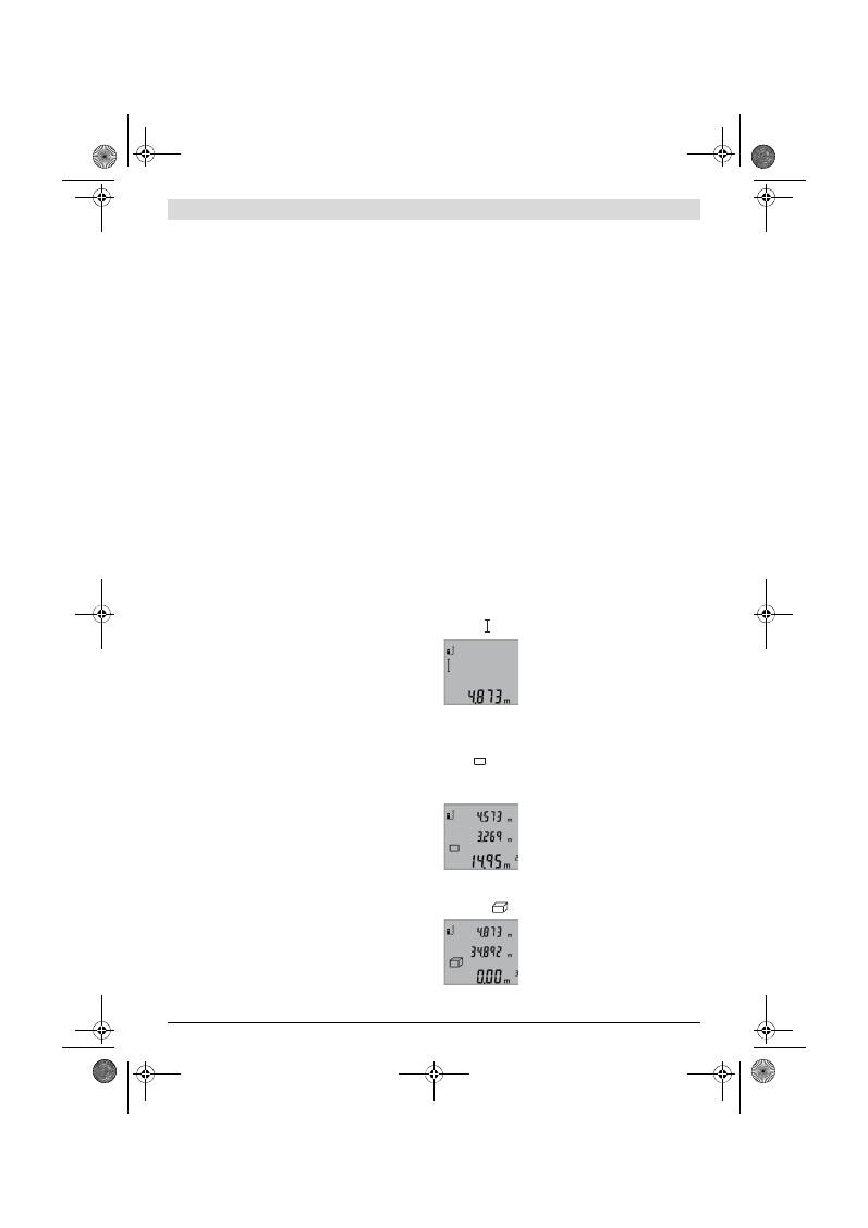
Dansk |
51
Bosch Power Tools
2 609 140 773 | (4.12.12)
terierne og akkuerne kan korrodere og aflade sig selv, hvis
de lagres i længere tid.
Brug
Ibrugtagning
Sørg for, at måleværktøjet altid er under opsyn og sluk
for måleværktøjet efter brug.
Andre personer kan blive
blændet af laserstrålen.
Beskyt måleværktøjet mod fugtighed og direkte sol-
stråler.
Udsæt ikke måleværktøjet for ekstreme temperaturer
eller temperatursvingninger.
Lad det f.eks. ikke ligge i
bilen i længere tid. Sørg altid for, at måleværtøjet er tem-
pereret ved større temperatursvingninger, før det tages i
brug. Ved ekstreme temperaturer eller temperatursving-
ninger kan måleværktøjets præcision forringes.
Undgå at udsætte måleværktøjet for voldsomme stød
eller fald.
Hvis måleværktøjet udsættes for stærke, udven-
dige påvirkninger, skal du altid gennemføre en nøjagtig-
hedskontrol, før der arbejdes videre med det (se „Nøjagtig-
hedskontrol af afstandsmåling“, side 53).
Tænd/sluk
Måleværktøjet kan
tændes
på følgende måder:
– Tryk på start-stop-tasten
4
: Måleværktøjet tændes og fin-
des i funktionen længdemåling. Laseren tændes ikke.
– Tryk på tasten måling
2
: Måleværktøj og laser tændes. Må-
leværktøjet findes i funktionen Længdemåling.
Ret ikke laserstrålen mod personer eller dyr og ret ikke
blikket ind i laserstrålen, heller ikke fra stor afstand.
Måleværktøjet
slukkes
ved at trykke lang tid på start-stop-ta-
sten
4
.
Trykkes der ikke på nogen taste på måleværktøjet i ca. 5 min,
slukkes måleværktøjet automatisk for at skåne batterierne.
Målemetode
Er måleværktøjet blevet tændt ved at trykke på tasten måling
2
, findes måleværktøjet altid i funktionen Længdemåling. An-
dre målefunktioner indstilles ved at trykke på den pågælden-
de funktionstaste (se „Målefunktioner“, side 51).
Som referenceniveau for målingen er måleværktøjets bagkant
valgt efter tændingen. Tryk på tasten referenceniveau
6
for at
ændre referenceniveauet (se „Vælg referenceniveau“,
side 51).
Anbring måleværktøjet med det valgte referenceniveau op ad
det ønskede startpunkt for målingen (f.eks. væg).
Laserstrålen tændes ved kort at trykke på tasten måling
2
.
Ret ikke laserstrålen mod personer eller dyr og ret ikke
blikket ind i laserstrålen, heller ikke fra stor afstand.
Ret laserstrålen mod målefladen. Målingen udløses ved igen
kort at trykke på tasten måling
2
.
I funktionen konstant måling starter målingen, så snart funkti-
onen tændes.
Måleværdien fremkommer typisk i løbet af 0,5 s og senest ef-
ter 4 s. Målingens varighed afhænger af afstanden til målefla-
den, lysforholdene og refleksionsegenskaberne ved målefla-
den. Når målingen er færdig, slukkes laserstrålen automatisk.
Udføres der ikke nogen måling ca. 20 s efter at strålen er ret-
tet mod målet, slukker laserstrålen automatisk for at skåne
batterierne.
Vælg referenceniveau (se Fig. A)
Til målearbejdet kan der vælges mellem tre forskellige refe-
renceniveauer:
– Bagkanten på måleværktøjet (f.eks. placering på vægge),
– Forkanten på måleværktøjet (f.eks. til måling fra en bord-
kant),
– Midten på gevindet
14
(f.eks. til målinger med stativ).
Referenceniveauet vælges ved at trykke på tasten
6
, til det
ønskede referenceniveau fremkommer i displayet. Hver gang
måleværktøjet tændes, fungerer bagkanten på måleværktøjet
som referenceniveau.
Displaybelysning
Displaybelysningen aktiveres automatisk afhængigt af, hvor
lyse omgivelserne er. Trykkes der ikke på nogen taste, efter at
displaybelysningen er blevet tændt, dæmpes denne for at
skåne batterierne.
Målefunktioner
Nem længdemåling (se Fig. B)
Til længdemålinger trykkes på tasten
9
, til visningen for læng-
demåling fremkommer i displayet.
Når laseren skal tændes og til måling tryk-
kes en gang kort på tasten måling
2
.
Måleværdien vises i resultatlinjen
b
.
Ved flere længdemålinger efter hinanden
vises resultaterne for de sidste målinger i
måleværdilinjerne
a
.
Flademåling (se Fig. C)
Til flademålinger trykkes på tasten
3
, til visningen for flade-
måling
fremkommer i displayet.
Mål herefter længde og bredde en ad gangen lige som ved en
længdemåling. Mellem de to målinger er laserstrålen tændt.
Når den anden måling er færdig, beregnes
fladen automatisk og vises i resultatlinjen
b
. De enkelte værdier står i måleværdilin-
jerne
a
.
Volumenmåling (se Fig. D)
Til volumenmålinger trykkes på tasten
3
, til visningen for volu-
menmåling
fremkommer i displayet.
Mål herefter længde, bredde og højde, li-
ge som ved en længdemåling. Mellem de
tre målinger er laserstrålen tændt.
OBJ_BUCH-1444-004.book Page 51 Tuesday, December 4, 2012 1:47 PM
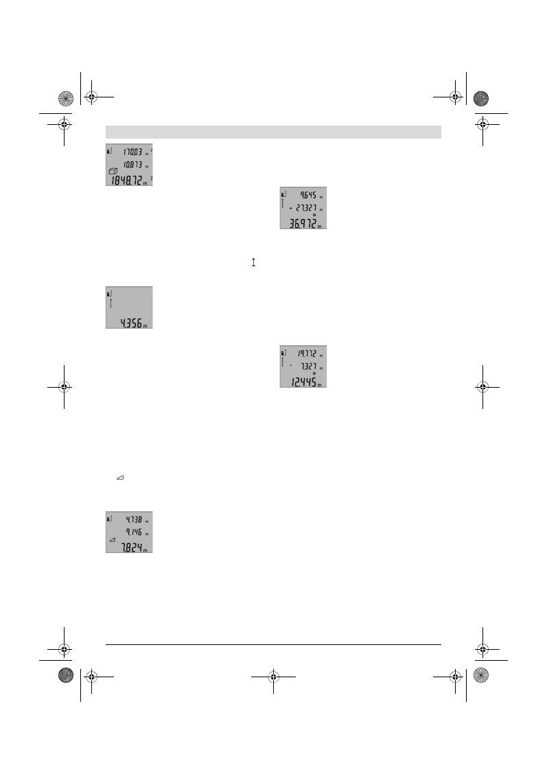
52
| Dansk
2 609 140 773 | (4.12.12)
Bosch Power Tools
Når den tredje måling er færdig, beregnes
volumenet automatisk og vises i resultat-
linjen
b
. De enkelte værdier står i måle-
værdilinjerne
a
.
Værdier over 999999 m
3
kan ikke vises, i
displayet fremkommer
„ERROR“
. Inddel
det volumen, der skal måles, i enkelte målinger, hvis værdier
du beregner separat og herefter samler.
Konstant måling (se Fig. E)
Ved den konstante måling kan måleværktøjet bevæges rela-
tivt i forhold til målet. Måleværdien aktualiseres ca. hver
0,5 sek. Du kan fjerne dig f.eks. fra en væg til den ønskede af-
stand, den aktuelle afstand kan aflæses hele tiden.
Til konstante målinger trykkes på tasten
9
, til visningen for
konstant måling fremkommer i displayet. Konstant måling
startes ved at trykke på tasten måling
2
.
Den aktuelle måleværdi vises i resultatlin-
jen
b
.
Trykkes på tasten måling
2
, afsluttes den
konstante måling. Den sidste måleværdi
vises i resultatlinjen
b
. Den konstante må-
ling starter igen ved at trykke på tasten
måling
2
en gang til.
Den konstante måling slukker automatisk efter 5 min. Den
sidste måleværdi vises i resultatlinjen
b
.
Indirekte højdemåling / Enkelt Pythagoras-måling (se Fig. F)
Den indirekte højdemåling bruges til at beregne afstande, der
ikke kan måles direkte, da strålen hindres af en forhindring el-
ler fordi der ikke står nogen målflade til rådighed som reflek-
tor. Korrekte resultater opnås kun, hvis de rette vinkler, der
kræves af den pågældende måling, overholdes nøje (den py-
thagoræiske læresætning).
Sørg for, at målingens referencepunkt (f.eks. bagkant på må-
leværktøj) bliver nøjagtigt samme sted ved alle målinger in-
den for en måleproces.
Mellem de enkelte målinger forbliver laserstrålen tændt.
Tryk på tasten
3
, til visningen for den enkelte Pythagoras-må-
ling
fremkommer i displayet.
Mål som ved en længdemåling strækningerne
„1“
og
„2“
i
denne rækkefølge. Sørg for, at der er en ret vinkel mellem
strækningen
„1“
og den søgte strækning
„X“
.
Når den sidste måling er færdig, vises re-
sultatet af den søgte strækning
„X“
i re-
sultatlinjen
b
. De enkelte værdier står i
måleværdilinjerne
a
.
Måleværdier slettes
Med et kort tryk på tasten
4
kan du slette den sidst beregnede
enkelte måleværdi i alle målefunktioner. Ved at trykke flere
gange kort på tasten slettes de enkelte måleværdier i om-
vendt rækkefølge.
Måleværdier adderes
Gennemfør altid først en hvilken som helst måling, før måle-
værdier kan adderes. Tryk så på plustasten
8
. I displayet
fremkommer
„+“
til bekræftelse.
Volumen eller flader adderes ved at trykke på plustasten
8
,
når den første, afsluttede måling er gennemført. I displayet
fremkommer
„+“
til bekræftelse til venstre for volumen-/flade-
symbolet.
Gennemfør så en yderligere måling.
Tryk en gang til på plustasten
8
for at kon-
trollere summen af de to målinger. Bereg-
ningen vises i måleværdilinjerne
a
, sum-
men ses i resultatlinjen
b
.
Når summen er beregnet, kan der adde-
res yderligere måleværdier til dette resul-
tat ved at trykke på plustasten
8
før målingen.
Henvisninger til addition:
– Længde-, flade- og volumenværdier kan ikke adderes blan-
det. Adderes f.eks. en længde- og en fladeværdi, fremkom-
mer efter tryk på plustasten
8
kort
„ERROR“
i displayet.
Herefter skifter måleværktøjet til den sidst aktive måle-
funktion.
– Der adderes altid resultatet af en måling (f.eks. volumen-
værdi), ved konstante målinger måleværdien i resultatlin-
jen
b
. Det er ikke muligt at addere enkelte måleværdier fra
måleværdilinjerne
a
.
Måleværdier subtraheres
Til subtraktion af måleværdier trykkes på
minustasten
5
, i displayet fremkommer til
bekræftelse
„–“
. Den yderligere frem-
gangsmåde er i analogi med „Måleværdier
adderes“.
Arbejdsvejledning
Generelle henvisninger
Modtagerlinsen
12
og udgangen på laserstrålen
11
må ikke
være tildækket under målingen.
Måleværktøjet må ikke bevæges, mens der måles (med und-
tagelse af funktionen konstant måling). Anbring derfor helst
måleværktøjet op ad en fast anslags- eller kontaktflade.
Påvirkninger af måleområdet
Måleområdet afhænger af lysforholdene og målfladens reflek-
tionsegenskaber. For bedre at kunne se laserstrålen, når der
arbejdes ude i det fri og når solen er meget stærk, anbefales
det at bruge de specielle laserbriller
19
(tilbehør) og lasermål-
tavlen
20
(tilbehør), eller sørg for at afskygge målfladen.
Påvirkninger af måleresultatet
På grund af fysiske effekter kan det ikke udelukkes, at der op-
står fejlmålinger, når der måles på forskellige overflader. Her-
under forstås:
– gennemsigtige overflader (f.eks. glas, vand),
– spejlende overflader (f.eks. poleret metal, glas),
– porøse overflader (f.eks. isoleringsmaterialer),
– strukturerede overflader (f.eks. råpuds, natursten).
Brug på disse overflader i givet fald laser-måltavlen
20
(tilbe-
hør).
Fejlmålinger er desuden mulige, hvis strålen rettes skråt mod
målflader.
OBJ_BUCH-1444-004.book Page 52 Tuesday, December 4, 2012 1:47 PM
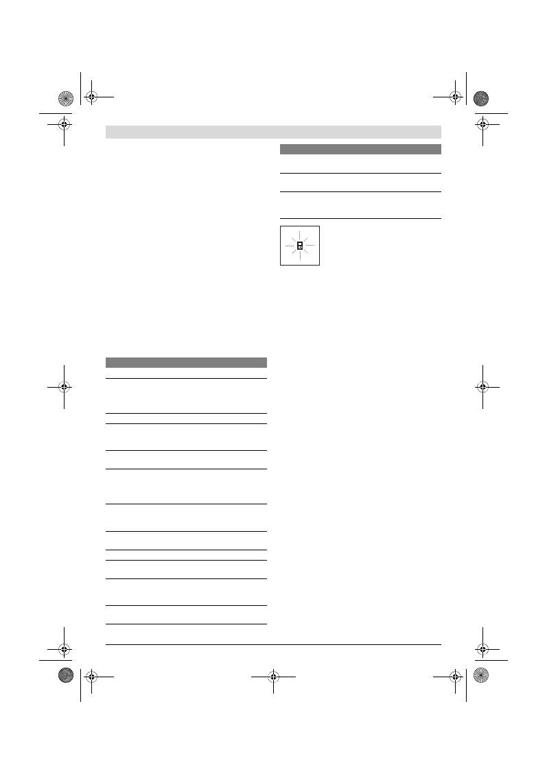
Dansk |
53
Bosch Power Tools
2 609 140 773 | (4.12.12)
Ligeledes kan luftlag med forskellige temperaturer eller indi-
rekte modtagede reflektioner påvirke måleværdien.
Nøjagtighedskontrol af afstandsmåling
Afstandsmålingens nøjagtighed kontrolleres på følgende må-
de:
– Vælg en uforanderlig målestrækning med en længde på ca.
1 til 10 m, som du kender længden på (f.eks. rumbredde,
døråbning). Målestrækningen skal ligge i det indvendige
rum, målingens målflade skal være glat og godt reflekte-
rende.
– Mål strækningen 10 gange i træk.
De enkelte målinger må max. afvige ±2 mm fra middelværdi-
en. Fasthold måleresultaterne i en måleprotokol, så det er
muligt at sammenligne nøjagtigheden af resultaterne på et se-
nere tidspunkt.
Arbejde med stativet (tilbehør)
Det er især nødvendigt at bruge et stativ ved store afstande.
Anbring måleværktøjet med 1/4"-gevindet
14
på hurtigskifte-
pladen til stativet
18
eller til et almindeligt fotostativ. Skru det
fast med hurtigskiftepladens stilleskrue.
Indstil referenceniveauet til målinger med stativ ved at trykke
tilsvarende på tasten
6
(referenceniveau gevind).
Fejl
–
Årsager og afhjælpning
Måleværktøjet, at hver enkelt måling gen-
nemføres korrekt. Konstateres en defekt,
blinker kun det symbol, der ses her til ven-
stre, i displayet. I dette tilfælde eller hvis
ovennævnte afhjælpningsforanstaltninger
ikke kan afhjælpe en fejl, afleveres måle-
værktøjet til din forhandler, der sørger for at lede det videre til
Bosch-kundeservice.
Vedligeholdelse og service
Vedligeholdelse og rengøring
Opbevar og transportér kun måleværktøjet i den medlevere-
de beskyttelsestaske.
Renhold måleværtøjet.
Dyp ikke måleværktøjet i vand eller andre væsker.
Tør snavs af værktøjet med en fugtig, blød klud. Anvend ikke
rengørings- eller opløsningsmidler.
Især modtagerlinsen
12
skal plejes på den samme omhyggeli-
ge måle som briller eller linsen på et fotoapparat.
Skulle måleværktøjet trods omhyggelig fabrikation og kontrol
alligevel holde op med at fungere, skal reparationen udføres
af et autoriseret servicecenter for Bosch el-værktøj. Forsøg
ikke at åbne måleværktøjet selv.
Måleværktøjets 10-cifrede typenummer (se typeskilt) skal al-
tid angives ved forespørgsler og bestilling af reservedele.
Send altid måleværktøjet til reparation i beskyttelsestasken
17
.
Kundeservice og brugerrådgivning
Kundeservice besvarer dine spørgsmål vedr. reparation og
vedligeholdelse af dit produkt samt reservedele. Eksplosions-
tegninger og informationer om reservedele findes også un-
der:
www.bosch-pt.com
Bosch brugerrådgivningsteamet vil gerne hjælpe dig med at
besvare spørgsmål vedr. vores produkter og deres tilbehør.
Dansk
Bosch Service Center
Telegrafvej 3
2750 Ballerup
Tlf. Service Center: 44898855
Fax: 44898755
E-Mail: vaerktoej@dk.bosch.com
Årsag
Afhjælpning
Temperaturadvarsel (f) blinker, måling er ikke mulig
Måleværktøjet er uden for drift-
stemperaturen fra – 10 °C til
+ 50 °C (i funktionen konstant må-
ling op til +40 °C).
Vent til måleværktøjet
har nået driftstempera-
tur
Visning „ERROR“ i displayet
Addition/subtraktion af målevær-
dier med forskellige måleenheder
Addér/fratræk kun måle-
værdier med samme må-
leenheder
Vinkel mellem laserstråle og mål er
for spids.
Forstør vinkel mellem la-
serstråle og mål
Målflade reflekterer for meget
(f.eks. spejl) eller for lidt (f.eks.
sort stof) eller omgivelseslys er for
stærkt.
Brug laser-måltavle
20
(tilbehør)
Udgang laserstråling
11
eller mod-
tagerlinse
12
er dugget (f.eks. på
grund af hurtig temperaturskift).
Tør udgang laserstråling
11
eller modtagerlinse
12
tør med en blød klud
Beregnet værdi er større end
999999 m/m
2
/m
3
.
Inddel beregning i mel-
lemskridt
Måleresultat ikke plausibelt
Målflade reflekterer ikke entydigt
(f.eks. vand, glas).
Afdæk målflade
Udgang laserstråling
11
eller mod-
tagerlinse
12
er tildækket.
Hold udgang lasestråling
11
eller modtagerlinse
12
fri
Forkert referenceniveau indstillet Vælg referenceniveau,
så det passer til måling
Forhindring i laserstrålens forløb
Laserpunkt skal ligge
komplet på målflade.
Visningen forbliver uændret, eller måleværktøjet reage-
rer uventet på tastetryk
Fejl i softwaren
Tag batterierne ud og
læg dem i igen, før måle-
værktøjet startes igen.
Årsag
Afhjælpning
OBJ_BUCH-1444-004.book Page 53 Tuesday, December 4, 2012 1:47 PM
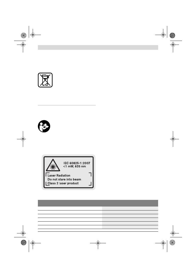
54
| Svenska
2 609 140 773 | (4.12.12)
Bosch Power Tools
Bortskaffelse
Måleværktøj, tilbehør og emballage skal genbruges på en mil-
jøvenlig måde.
Smid ikke måleværktøj og akkuer/batterier ud sammen med
det almindelige husholdningsaffald!
Gælder kun i EU-lande:
Iht. det europæiske direktiv 2002/96/EF
skal kasseret måleværktøj og iht. det euro-
pæiske direktiv 2006/66/EF skal defekte
eller opbrugte akkuer/batterier indsamles
separat og genbruges iht. gældende miljø-
forskrifter.
Ret til ændringer forbeholdes.
Svenska
Säkerhetsanvisningar
Samtliga anvisningar bör läsas för effektiv
och säker användning av mätverktyget.
Håll varselskyltarna på mätverktyget tyd-
ligt läsbara. TA VÄL VARA PÅ ANVISNING-
ARNA.
Se upp – om andra hanterings- eller justeringsutrust-
ningar än de som angivits här eller andra metoder
används finns risk för farlig strålningsexposition.
Mätverktyget levereras med en varningsskylt på engel-
ska (märkt i presentationen av mätverktyget på grafik-
sidan med nummer 15).
Klistra medföljande dekal i ditt eget språk över engel-
ska texten på varningsskylten innan du tar elverktyget
i bruk.
Rikta aldrig laserstrålen mot personer eller djur och
rikta inte heller själv blicken mot laserstrålen.
Detta
mätverktyg alstrar laserstrålning i laserklass 2 enligt
IEC 60825-1. Risk finns att strålen bländar personer.
Lasersiktglasögonen får inte användas som skydds-
glasögon.
Lasersiktglasögonen förbättrar laserstrålens
siktbarhet men skyddar inte mot laserstrålning.
Lasersiktglasögonen får inte användas som solglas-
ögon eller i trafiken.
Lasersiktglasögonen skyddar inte
fullständigt mot UV-strålning och reducerar förmågan att
uppfatta färg.
Låt endast kvalificerad fackpersonal reparera mät-
verktyget med originalreservdelar.
Detta garanterar att
mätverktygets säkerhet upprätthålls.
Låt inte barn utan uppsikt använda lasermätverktyget.
Risk finns för att personer oavsiktligt bländas.
Mätverktyget får inte användas i explosionsfarlig miljö
som innehåller brännbara vätskor, gaser eller damm.
Mätverktyg kan ge upphov till gnistor som antänder dam-
met eller ångorna.
Produkt- och kapacitetsbeskrivning
Fäll upp sidan med illustration av mätverktyget och håll sidan
uppfälld när du läser bruksanvisningen.
Ändamålsenlig användning
Mätverktyget är avsett för mätning av distans, längd, höjd,
avstånd och för beräkning av ytor och volymer. Mätverktyget
är avsett för mätningar inom- och utomhus.
Tekniska data
Digital laseravståndsmätare
GLM 50
Professional
Produktnummer
3 601 K72 2..
Mätområde
0,05 –50 m
A)
Mätnoggrannhet (typisk)
±1,5 mm
B)
Minsta indikeringsenhet
1 mm
Driftstemperatur
–10 °C...+50 °C
C)
Lagringstemperatur
–20 °C...+70 °C
OBJ_BUCH-1444-004.book Page 54 Tuesday, December 4, 2012 1:47 PM

Svenska |
55
Bosch Power Tools
2 609 140 773 | (4.12.12)
Illustrerade komponenter
Numreringen av komponenterna hänvisar till illustration av
mätverktyget på grafiksidan.
1
Display
2
Knapp mätning
3
Knapp för yt-, volym- och indirekt höjdmätning (Pythago-
ras)
4
Raderingsknapp / På-Av-knapp **
5
Minusknapp
6
Knapp för val av referensplan
7
Fäste för handlovsrem
8
Plusknapp
9
Knapp längd- och kontinuerlig mätning
10
Batterifackets lock
11
Laserstrålens utgång
12
Mottagarlins
13
Serienummer
14
1/4"-gänga
15
Laservarningsskylt
16
Spärr på batterifackets lock
17
Skyddsfodral
18
Stativ*
19
Lasersiktglasögon*
20
Lasermåltavla*
* I bruksanvisningen avbildat och beskrivet tillbehör ingår inte i
standardleveransen.
** Håll knappen nedtryckt för anrop av tillsatsfunktionerna.
Indikeringselement
a
Mätvärdesrader
b
Resultatrad
c
Mätfunktioner
d
Lasern påslagen
e
Mätningens referensplan
f
Temperaturvarning
g
Batterivarning
h
Felindikering
”ERROR”
Relativ luftfuktighet max.
90 %
Laserklass
2
Lasertyp
635 nm, <1 mW
Laserstrålens diameter (vid 25 °C) ca
– på 10 m avstånd
– på 50 m avstånd
6 mm
35 mm
Avkopplingsautomatik efter ca
– Laser
– mätverktyg (utan mätning)
20 s
5 min
Batterier
Battericeller
2 x 1,5 V LR03 (AAA)
2 x 1,2 V HR03 (AAA)
Batteriets brukstid ca
– punktmätningar
– kontinuerlig mätning
10000
D)
2,5 h
D)
Vikt enligt EPTA-Procedure 01/2003
0,14 kg
Mått
53 x 114 x 30 mm
Kapslingsklass
IP 54 (damm- och spolsäker)
Digital laseravståndsmätare
GLM 50
Professional
A) Räckvidden blir allt större ju bättre laserljuset reflekterar från målytan (spridande, inte speglande) och ju klarare laserpunkten är i relation till omgiv-
ningsljuset (inomhus, skymning). Vid ogynnsamma villkor (t.ex. mätning utomhus vid kraftigt solsken) kan det vara nödvändigt att använda en mål-
tavla.
B) Vid mätning från mätverktygets bakre kant. Vid ogynnsamma förhållanden som t. ex. kraftigt solsken eller dåligt reflekterande yta kan avvikelsen
uppgå till
±
10 mm på ett avstånd om 50 m. Vid ogynnsamma förhållanden måste man räkna med en avvikelse på
±
0,05 mm/m.
C) Vid kontinuerlig mätning är max. drifttemperatur +40
°C
.
D) Med 1,2 V-battericeller kan ett mindre antal mätningar utföras än med 1,5 V-batterier. Angiven batterilivslängd hänför sig till mätningar utan dis-
playbelysning.
Serienumret
13
på typskylten identifierar mätverktyget entydigt.
Längdmätning
Kontinuerlig mätning
Ytmätning
Volymmätning
Enkel Pythagorasmätning
OBJ_BUCH-1444-004.book Page 55 Tuesday, December 4, 2012 1:47 PM
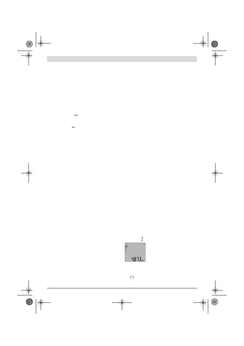
56
| Svenska
2 609 140 773 | (4.12.12)
Bosch Power Tools
Montage
Insättning/byte av batterier
För mätverktyget rekommenderar vi alkali-mangan-primär-
batterier eller laddningsbara sekundärbatterier.
Med 1,2 V-sekundärbatterier kan ett mindre antal mätningar
utföras än med 1,5 V-primärbatterier.
För att öppna batterifackets lock
10
tryck spärren
16
och ta
bort locket. Sätt in batterierna. Kontrollera korrekt polning
enligt märkning på batterifackets insida.
Vid insättning av batterierna kontrollera korrekt polning enligt
bild i batterifacket.
Dyker batterisymbolen
första gången upp på displayen
kan ännu minst 100 mätningar utföras. Funktionen kontinuer-
lig mätning är avaktiverad.
När batterisymbolen
blinkar, måste batterierna resp. bat-
tericellerna bytas ut. Mätning kan inte längre utföras.
Alla batterier ska bytas samtidigt. Använd endast batterier av
samma fabrikat och med samma kapacitet.
Ta bort batterierna om mätverktyget inte används
under en längre tid.
Batterierna kan vid långtidslagring
korrodera och självurladdas.
Drift
Driftstart
Lämna inte påkopplat mätverktyg utan uppsikt, stäng
alltid av mätverktyget efter avslutat arbete.
Risk finns
att andra personer bländas av laserstrålen.
Skydda mätverktyget mot väta och direkt solljus.
Utsätt inte mätverktyget för extrema temperaturer
eller temperaturväxlingar.
Lämna inte mätverktyget
under en längre tid t.ex. i bilen. Om mätverktyget varit
utsatt för större temperaturväxlingar låt det balanseras
innan du använder det. Vid extrem temperatur eller tempe-
raturväxlingar kan mätverktygets precision påverkas men-
ligt.
Undvik att utsätta mätverktyget för kraftiga stötar
eller fall.
Efter kraftig yttre påverkan ska mätverktygets
noggrannhet kontrolleras innan arbetet fortsättes (se
”Noggrannhetskontroll av avståndsmätning”, sidan 58).
In- och urkoppling
För
Inkoppling
av mätverktyget finns följande alternativ.
– Tryck På-Av-knappen
4
: Mätverktyget slås på och står i
funktionen längdmätning. Lasern slås inte på.
– Tryck knappen Mätning
2
: Mätverktyget och lasern slås på.
Mätverktyget står i funktionen längdmätning.
Rikta aldrig laserstrålen mot människor eller djur och
rikta inte heller blicken mot laserstrålen även om du
står på längre avstånd.
För
frånkoppling
av mätverktyget tryck på På-Av-knappen
4
.
Om under ca 5 minuter ingen knapp trycks på mätverktyget
stängs det automatiskt av för att skona batterierna.
Mätning
När mätverktyget slås på genom att trycka på knappen Mät-
ning
2
står det alltid i funktionen längdmätning. Andra mät-
funktioner ställs in med respektive funktionsknapp (se ”Mät-
funktioner”, sidan 56).
Vid inkoppling är mätverktygets bakkant referensplanet för
mätning. Med knappen referensplan
6
kan referensplanet
ändras (se ”Val av referensplan”, sidan 56).
Lägg upp mätverktyget med valt referensplan mot önskad
startpunkt för mätning (t. ex. vägg).
Tryck för inkoppling av laserstrålen knappen Mätning
2
.
Rikta aldrig laserstrålen mot människor eller djur och
rikta inte heller blicken mot laserstrålen även om du
står på längre avstånd.
Sikta laserstrålen mot målytan. Tryck för utlösning av mätning
på nytt helt kort knappen Mätning
2
.
I funktionen kontinuerlig mätning startar mätningen genast
när funktionen kopplas på.
Mätvärdet visas i typiska fall mellan 0,5 s och högst 4 s. Mät-
tiden är beroende av avstånd, ljusförhållanden och målytans
reflexionsegenskaper. Efter avslutad mätning kopplas laser-
strålen automatiskt från.
Om ca 20 s efter insiktning ingen mätning utförs, slås laser-
strålen automatiskt från för att skona batterierna.
Val av referensplan (se bild A)
För mätning kan tre olika referensplan väljas:
– mätverktygets bakre kant (t. ex. vid anläggning mot vägg),
– mätverktygets främre kant (t. ex. vid mätning från bords-
kant),
– från mitten på gängan
14
(t. ex. för mätning med stativ).
För val av referensplan tryck upprepade gånger knappen
6
tills önskat referensplan visas på displayen. Vid varje påslag
är mätverktygets bakre kant förinställd som referensplan.
Displaybelysning
Displaybelysningen aktiveras automatiskt i relation till omgiv-
ningen ljusstyrka. Om ingen knapp trycks efter det displaybe-
lysning slagits på, slås displaybelysningen från för att skona
batterierna.
Mätfunktioner
Enkel längdmätning (se bild B)
Tryck för längdmätning upprepade gånger knappen
9
tills
längdmätning visas på displayen.
Tryck för inkoppling av lasern och för mät-
ning en gång kort ned knappen Mätning
2
.
Mätvärdet visas i resultatraden
b
.
Vid flera längdmätningar i följd visas
resultaten av de senaste mätningarna i
mätvärdesraderna
a
.
Ytmätning (se bild C)
Tryck för ytmätning upprepade gånger knappen
3
tills ytmät-
ning
visas på displayen.
OBJ_BUCH-1444-004.book Page 56 Tuesday, December 4, 2012 1:47 PM
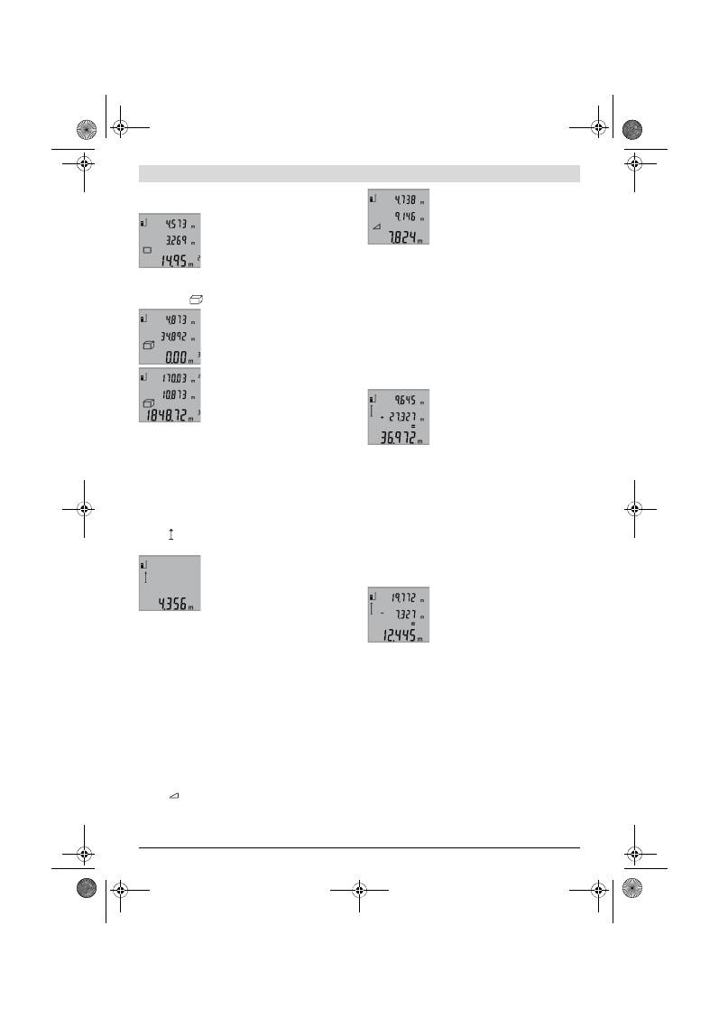
Svenska |
57
Bosch Power Tools
2 609 140 773 | (4.12.12)
Mät sedan efter varandra längd och bredd som vid mätning av
längd. Mellan de båda mätningar kvarstår lasern påkopplad.
Efter andra mätningen beräknas ytan
automatiskt och visas i resultatraden
b
.
Enkelmätvärden visas i mätvärdesra-
derna
a
.
Volymmätning (se bild D)
Tryck för volymmätning upprepade gånger knappen
3
tills
volymmätning
visas på displayen.
Mät sedan efter varandra längd, bredd
och höjd som vid mätning av längd. Mel-
lan de båda mätningarna kvarstår lasern
påkopplad.
Efter tredje mätningen beräknas volymen
automatiskt och visas i resultatraden
b
.
Enkelmätvärdena visas i mätvärdesra-
derna
a
.
Värden överskridande 999999 m
3
kan
inte indikeras och displayen visar
”ERROR”
. Dela upp volymen för mindre enkelmätningar för
separat beräkning av värdena och sammanfatta dem.
Kontinuerlig mätning (se bild E)
Vid kontinuerlig mätning kan mätverktyget förflyttas i förhål-
lande till målet varvid mätvärdet aktualiseras ca 0,5 s var.
Mätverktyget kan t.ex. flyttas från en vägg till önskat avstånd,
aktuellt avstånd kan hela tiden avläsas.
Tryck för kontinuerlig mätning knappen
9
tills kontinuerlig
mätning visas på displayen Tryck för start av kontinuerlig
mätning knappen Mätning
2
.
Aktuellt mätvärde visas i resultatraden
b
.
Genom att trycka på knappen Mätning
2
avslutas den kontinuerliga mätningen.
Sista mätvärdet visas i resultatraden
b
.
Vid upprepad tryckning på knappen Mät-
ning
2
startar kontinuerlig mätning på
nytt.
Den kontinuerliga mätningen slås automatiskt från efter
5 min. Sista mätvärdet visas i resultatraden
b
.
Indirekt höjdmätning / Enkel Pythagorasmätning
(se bild F)
Indirekta höjdmätningen används för att mäta avstånd som
inte kan mätas direkt, då strålen stöter mot hinder eller en
reflekterande målyta saknas. Korrekt resultat uppnås endast
när mätsträckan bildar en exakt rät vinkel (Pythagoras sats).
Se till att mätningens referenspunkt (t. ex. mätverktygets
bakkant) vid alla enkelmätningar inom mätprocessen förblir
exakt på samma ställe.
Mellan enkelmätningarna kvarstår lasern påkopplad.
Tryck upprepade gånger knappen
3
tills enkel Pythagoras-
mätning
visas på displayen.
Mät som vid en längdmätning sträckorna
”1”
och
”2”
i denna
ordningsföljd Se till att en rät vinkel bildas mellan sträckan
”1”
och den sökta sträckan
”X”
.
Efter sista mätningen visas resultatet av
sökt sträcka
”E”
i resultatraden
b
. Enkel-
mätvärdena visas i mätvärdesraderna
a
.
Radera mätvärden
Genom att kort trycka på knappen
4
kan det senast framtagna
mätvärdet raderas i alla mätfunktioner. Vid upprepad tryck-
ning på knappen raderas de enskilda mätvärdena i omvänd
ordningsföljd.
Addition av mätvärden
För addering av mätvärden utför först en valfri mätning. Tryck
sedan plusknappen
8
. På displayen bekräftas
”+”
.
För addering av volymer eller ytor, tryck efter den första
avslutade mätningen plusknappen
8
. På displayen bekräftas
”+”
till vänster om volym-/ytsymbolen.
Utför sedan en andra mätning.
Tryck för att avfråga summan av båda
mätningarna en gång till på plusknappen
8
. Beräkningen visas i mätvärdesraderna
a
, summan står i resultatraden
b
.
Efter beräkning av summan kan ytterliga
mätvärden adderas när plusknappen
8
trycks före mätningen.
Anvisningar för addering:
– Blandade längd-, yt- och volymvärden kan inte adderas.
Om t. ex. ett längd- och ett ytvärde adderas, visas när plus-
knappen
8
trycks helt kort
”ERROR”
på displayen. Däref-
ter kopplar mätverktyget om till senast aktiv mätfunktion.
– Ett mätresultat (t.ex. volymvärde) adderas; vid kontinuer-
lig mätning mätvärdet som indikeras i resultatraden
b
.
Addering av enkelmätvärden ur mätvärdesraderna
a
är
inte möjlig.
Subtrahera mätvärden
För subtrahering av mätvärden tryck
minusknappen
5
, på displayen visas för
bekräftelse
”–”
. Fortsatt förlopp är ana-
logt med ”Addition av mätvärden”.
Arbetsanvisningar
Allmänna anvisningar
Mottagarlinsen
12
och laserstrålens utgång
11
får under mät-
ning inte vara övertäckta.
Mätverktyget får under mätning inte förflyttas (med undantag
av funktionen kontinuerlig mätning). Lägg därför upp mät-
verktyget mot fast anslag eller anliggningsyta.
Inverkan på mätområdet
Mätområdets storlek är beroende av ljusförhållandena och
målytans reflexionsegenskaper. Använd för bättre siktbarhet
av laserstrålen vid arbeten utomhus och vid kraftigt solsken
lasersiktglasögonen
19
(tillbehör) och lasermåltavlan
20
(till-
behör) eller skugga målytan.
OBJ_BUCH-1444-004.book Page 57 Tuesday, December 4, 2012 1:47 PM
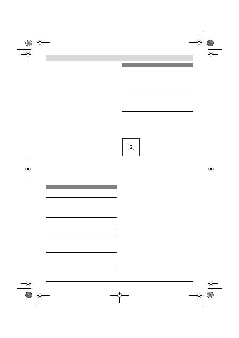
58
| Svenska
2 609 140 773 | (4.12.12)
Bosch Power Tools
Inverkan på mätresultatet
På grund av fysikaliska effekter kan man inte utesluta en fel-
mätning vid mätning av olika ytor. Detta gäller bl.a. för:
– transparenta ytor (t.ex. glas, vatten),
– reflekterande ytor (t.ex. polerad metall, glas),
– porösa ytor (t.ex. isoleringsmaterial),
– ytor med struktur (t.ex. grovputs, natursten).
Använd eventuellt för dessa ytor lasermåltavlan
20
(tillbe-
hör).
Felaktig mätning är möjlig på snett inriktade målytor.
Dessutom kan luftskikt med olika temperatur eller indirekt
reflexion påverka mätvärdet.
Noggrannhetskontroll av avståndsmätning
Avståndsmätningens noggrannhet kan kontrolleras så här:
– Välj en oföränderlig mätsträcka på ca 1 till 10 m vars
exakta längd är känd (t. ex. rummets bredd, dörröppning).
Mätsträckan måste ligga inomhus, målytan för mätning
vara plan och reflektera bra.
– Mät sträckan 10 gånger i följd.
Enkelmätningarna får avvika högst ±2 mm från medelvärdet.
Protokollera mätningarna för att vid senare tidpunkt kunna
jämföra noggrannheten.
Användning med stativ (tillbehör)
Ett stativ krävs framför allt för mätning på längre avstånd.
Lägg upp mätverktyget med 1/4"-gängan
14
på stativets
18
snabbväxlingsplatta eller på ett gängse kamerastativ. Skruva
fast mätverktyget med snabbväxlingsplattans låsskruv.
Ställ in referensplanet för mätning med stativ genom att
trycka på knappen
6
(referensplan gänga).
Fel
–
Orsak och åtgärd
Mätverktyget övervakar korrekt funktion
vid varje mätning. Om ett fel lokaliseras,
blinkar på displayen endast bredvid visad
symbol. I detta fall eller om ovan beskrivna
åtgärder inte kan avhjälpa felet ska mät-
verktyget via återförsäljaren skickas till
Bosch-service.
Underhåll och service
Underhåll och rengöring
Lagra och transportera mätverktyget endast i det skydds-
fodral som medlevererats.
Se till att mätverktyget alltid hålls rent.
Mätverktyget får inte doppas i vatten eller andra vätskor.
Torka av mätverktyget med en fuktig, mjuk trasa. Använd inte
rengörings- eller lösningsmedel.
Vårda speciellt mottagarlinsen
12
lika omsorgsfullt som glas-
ögonen eller kameralinsen.
Om störningar uppstår i mätverktyget trots exakt tillverkning
och sträng kontroll bör reparationen utföras av en auktorise-
rad serviceverkstad för Bosch elverktyg. Ta inte isär mätverk-
tyget på egen hand.
Var vänlig ange vid förfrågningar och reservdelsbeställningar
produktnummer som består av 10 siffror och som finns på
mätverktygets typskylt.
För reparation ska mätverktyget skickas in i skyddsfodralet
17
.
Kundtjänst och användarrådgivning
Kundservicen ger svar på frågor beträffande reparation och
underhåll av produkter och reservdelar. Sprängskisser och
information om reservdelar hittar du på:
www.bosch-pt.com
Bosch användarrådgivningsteamet hjälper gärna vid frågor
som gäller våra produkter och tillbehör.
Orsak
Åtgärd
Temperaturindikeringen (f) blinkar, mätning är inte möj-
lig
Mätverktygets drifttemperatur lig-
ger utanför intervallet – 10 °C till
+ 50 °C (vid funktionen kontinuer-
lig mätning till + 40 °C).
Vänta tills mätverktyget
uppnått driftstempera-
tur
Indikering ”ERROR” på displayen
Addition/subtraktion av mätvär-
den med olika mätenheter
Addera/subtrahera
endast mätvärden med
samma mätenhet
Vinkeln mellan laserstrålen och
målet är spetsig.
Förstora vinkeln mellan
laserstrålen och målet
Målytan reflekterar för kraftigt
(t.ex. spegel) resp. för svagt
(t.ex. svart tyg) eller omgivning-
ens ljus är för kraftigt.
Använd lasermåltavla
20
(tillbehör)
Utgången för laserstrålen
11
eller
mottagarlinsen
12
är immig (t.ex.
genom snabb temperaturväxling).
Torka med mjuk trasa av
laserstrålens utgång
11
eller mottagarlinsen
12
Beräknat värde överskrider
999999 m/m
2
/m
3
.
Dela upp beräkningen i
mellansteg
Orimligt mätresultat
Målytan reflekterar inte entydigt
(t.ex. vatten, glas).
Täck över målytan
Utgången för laserstrålning
11
resp. mottagarlinsen
12
är över-
täckt.
Utgången för laserstrål-
ning
11
resp. mottagar-
linsen
12
ska avtäckas
Fel referensplan inställt
Välj referensplanet som
matchar mätningen
Hinder i laserstrålens förlopp
Laserpunkten måste
ligga fullständigt på mål-
ytan.
Indikeringen förblir oförändrad eller mätverktyget rea-
gerar oväntat när knapp trycks
Fel i programmet
Ta bort batterierna och
starta mätverktyget på
nytt efter det de åter
satts in.
Orsak
Åtgärd
OBJ_BUCH-1444-004.book Page 58 Tuesday, December 4, 2012 1:47 PM
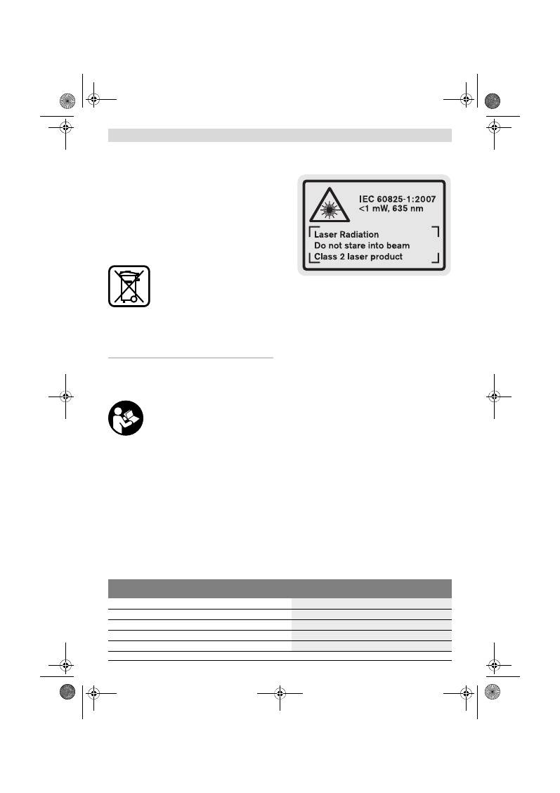
Norsk |
59
Bosch Power Tools
2 609 140 773 | (4.12.12)
Svenska
Bosch Service Center
Telegrafvej 3
2750 Ballerup
Danmark
Tel.: (020) 414455 (inom Sverige)
Fax: (011) 187691
Avfallshantering
Mätverktyg, tillbehör och förpackning ska omhändertas på
miljövänligt sätt för återvinning.
Släng inte mätverktyg och inte heller batterier i hushållsavfall!
Endast för EU-länder:
Enligt europeiska direktivet 2002/96/EG
måste obrukbara mätverktyg och enligt
europeiska direktivet 2006/66/EG felak-
tiga eller förbrukade batterier separat
omhändertas och på miljövänligt sätt läm-
nas in för återvinning.
Ändringar förbehålles.
Norsk
Sikkerhetsinformasjon
Les og følg alle anvisningene, for å kunne
arbeide farefritt og sikkert med måleverk-
tøyet. Gjør aldri varselskilt på måleverk-
tøyet uleselig. TA GODT VARE PÅ DISSE IN-
STRUKSENE.
OBS! Hvis det brukes andre betjenings- eller juste-
ringsinnretninger enn de vi har angitt her eller det utfø-
res andre bruksmetoder, kan dette føre til en farlig
stråle-eksponering.
Måleverktøyet leveres med et advarselsskilt på en-
gelsk (på bildet av måleverktøyet på bildesiden er det-
te merket med nummer 15).
Lim en norsk etikett over dette engelske advarselsskil-
tet før du tar apparatet i bruk for første gang.
Rett aldri laserstrålen mot personer eller dyr og se ikke
selv inn i laserstrålen.
Dette måleverktøyet lager laser-
stråling i laserklasse 2 jf. IEC 60825-1. Du kan da blende
personer.
Bruk laserbrillene aldri som beskyttelsesbriller.
Laser-
brillene er til bedre registrering av laserstrålen, men de be-
skytter ikke mot laserstrålingen.
Bruk laserbrillene aldri som solbriller eller i trafikken.
Laserbrillene gir ingen fullstendig UV-beskyttelse og redu-
serer fargeregistreringen.
Måleverktøyet skal alltid kun repareres av kvalifisert
fagpersonale og kun med originale reservedeler.
Slik
opprettholdes måleverktøyets sikkerhet.
La aldri barn bruke laser-måleverktøyet uten oppsyn.
Du kan ufrivillig blende personer.
Ikke arbeid med måleverktøyet i eksplosjonsutsatte
omgivelser – der det befinner seg brennbare væsker,
gass eller støv.
I måleverktøyet kan det oppstå gnister
som kan antenne støv eller damper.
Produkt- og ytelsesbeskrivelse
Brett ut utbrettssiden med bildet av måleverktøyet, og la den-
ne siden være utbrettet mens du leser bruksanvisningen.
Formålsmessig bruk
Måleverktøyet er beregnet til måling av distanser, lengder,
høyder, avstander og til beregning av flater og volumer. Måle-
verktøyet er egnet til målinger både innendørs og utendørs.
Tekniske data
Digital laser-avstandsmåler
GLM 50
Professional
Produktnummer
3 601 K72 2..
Måleområde
0,05 –50 m
A)
Målenøyaktighet (typisk)
±1,5 mm
B)
Minste indikatorenhet
1 mm
Driftstemperatur
–10 °C...+50 °C
C)
OBJ_BUCH-1444-004.book Page 59 Tuesday, December 4, 2012 1:47 PM
60
| Norsk
2 609 140 773 | (4.12.12)
Bosch Power Tools
Illustrerte komponenter
Nummereringen av de illustrerte komponentene gjelder for
bildet av måleverktøyet på illustrasjonssiden.
1
Display
2
Tast for måling
3
Tast for flate-, volum- og indirekte høydemåling (Pytha-
goras)
4
Slettetast / på-/av-tast **
5
Minustast
6
Tast til valg av referansenivå
7
Feste for bæreløkken
8
Plusstast
9
Tast for lengde- og kontinuerlig måling
10
Deksel til batterirom
11
Utgang laserstråling
12
Mottakerlinse
13
Serienummer
14
1/4"-gjenger
15
Laser-advarselsskilt
16
Låsing av batteridekselet
17
Beskyttelsesveske
18
Stativ*
19
Laserbriller*
20
Laser-målplate*
* Illustrert eller beskrevet tilbehør inngår ikke i standard-leveran-
sen.
** Hold tasten trykt inne til aktivering av de utvidede funksjonene.
Visningselementer
a
Måleverdilinjer
b
Resultatlinje
c
Målefunksjoner
d
Laser innkoblet
e
Referansenivå for målingen
f
Temperaturvarsel
g
Batterivarsel
h
Feilmelding
«ERROR»
Lagertemperatur
–20 °C...+70 °C
Relativ luftfuktighet max.
90 %
Laserklasse
2
Lasertype
635 nm, <1 mW
Diameter laserstråle (ved 25 °C) ca.
– på 10 m avstand
– på 50 m avstand
6 mm
35 mm
Automatisk utkobling etter ca.
– Laser
– Måleverktøy (uten måling)
20 s
5 min
Batterier
Battericeller
2 x 1,5 V LR03 (AAA)
2 x 1,2 V HR03 (AAA)
Batterilevetid ca.
– Enkeltmålinger
– Kontinuerlig måling
10000
D)
2,5 h
D)
Vekt tilsvarende EPTA-Procedure 01/2003
0,14 kg
Mål
53 x 114 x 30 mm
Beskyttelsestype
IP 54 (støv- og sprutvannbeskyttet)
Digital laser-avstandsmåler
GLM 50
Professional
A) Rekkevidden blir større, jo bedre laserlyset reflekteres av målets overflate (strøende, ikke speilende) og jo lysere laserpunktet er i forhold til omgi-
velseslyset (innendørs rom, skumring). Ved ugunstige vilkår (f.eks. måling utendørs med sterk sol) kan det være nødvendig å bruke en måltavle.
B) Ved måling fra bakkanten på måleverktøyet. Ved ugunstige vilkår som f.eks. sterk sol eller dårlig reflekterende overflate er det maksimale avviket
±
10 mm på 50 m. Ved gunstige vilkår må det regnes med en innflytelse på
±
0,05 mm/m.
C) I funksjonen for kontinuerlig måling er den maksimale driftstemperaturen +40
°C
.
D) Med 1,2-V-battericeller er færre målinger mulig enn med 1,5-V-batterier. Den angitte batterilevetiden gjelder for måling uten displaybelysning.
Serienummeret
13
på typeskiltet er til en entydig identifisering av måleverktøyet.
Lengdemåling
Kontinuerlig måling
Flatemåling
Volummåling
Enkel Pythagorasmåling
OBJ_BUCH-1444-004.book Page 60 Tuesday, December 4, 2012 1:47 PM
Norsk |
61
Bosch Power Tools
2 609 140 773 | (4.12.12)
Montering
Innsetting/utskifting av batterier
Til drift av måleverktøyet anbefales det å bruke alkali-man-
gan-batterier eller oppladbare batterier.
Med 1,2-V-batterier er færre målinger mulig enn med 1,5-V-
batterier.
Til åpning av batteridekselet
10
trykker du låsen
16
og tar av
batteridekselet. Sett inn de vanlige batteriene hhv. de opp-
ladbare batteriene. Pass på korrekt poling som vist på inner-
siden av batterirommet.
Ved innsetting av de vanlige hhv. oppladbare batteriene må
du passe på rett poling i henhold til bildet i batterirommet.
Når batterisymbolet
vises for første gang på displayet, er
minst 100 enkeltmålinger fremdeles mulig. Funksjonen for
kontinuerlig måling er deaktivert.
Når batterisymbolet
blinker må du skifte ut batteriene hhv.
battericellene. Det er ikke lenger mulig å utføre målinger.
Skift alltid ut alle de vanlige batteriene hhv. de oppladbare
batteriene på samme tid. Bruk kun vanlige batterier eller opp-
ladbare batterier fra en produsent og med samme kapasitet.
Ta de vanlige batteriene hhv. de oppladbare batteriene
ut av måleverktøyet, når du ikke bruker det over lengre
tid.
De vanlige og de oppladbare batteriene kan korrodere
ved lengre tids lagring og lades ut automatisk.
Bruk
Igangsetting
Ikke la det innkoblede måleverktøyet stå uten oppsyn
og slå måleverktøyet av etter bruk.
Andre personer kan
blendes av laserstrålen.
Beskytt måleverktøyet mot fuktighet og direkte sol-
stråling.
Ikke utsett måleverktøyet for ekstreme temperaturer
eller temperatursvingninger.
La det f.eks. ikke ligge i bi-
len over lengre tid. La måleverktøyet først tempereres ved
større temperatursvingninger før du tar det i bruk. Ved ek-
streme temperaturer eller temperatursvingninger kan pre-
sisjonen til måleverktøyet innskrenkes.
Unngå heftige støt eller fall for måleverktøyet.
Etter
sterke ytre innvirkninger på måleverktøyet bør du alltid ut-
føre en presisjonstest før du arbeider videre (se «Presi-
sjonskontroll av avstandsmålingen», side 63).
Inn-/utkobling
Til
innkopling
av måleverktøyet har du følgende muligheter:
– Trykking på på-/av-tasten
4
: Måleverktøyet koples inn og
befinner seg i funksjonen for lengdemåling. Laseren koples
ikke inn.
– Trykking på tasten for måling
2
: Måleverktøy og laser ko-
ples inn. Måleverktøyet befinner seg i funksjonen for leng-
demåling.
Rett aldri laserstrålen mot personer eller dyr og se ikke
selv inn i laserstrålen, heller ikke fra lang avstand.
Til
utkobling
av måleverktøyet trykker du lenge på på-/av-tas-
ten
4
.
Hvis det i ca. 5 min ikke trykkes en tast på måleverktøyet, ko-
bler måleverktøyet seg automatisk ut til skåning av batterie-
ne.
Måling
Etter innkopling ved å trykke på måletasten
2
befinner måle-
verktøyet seg alltid i lengdemålings-funksjonen. Andre måle-
funksjoner kan du innstille ved å trykke på den aktuelle funk-
sjonstasten (se «Målefunksjoner», side 61).
Som referansenivå for målingen er det valgt bakkanten på må-
leverktøyet etter innkopling. Ved å trykke på tasten for refe-
ransenivå
6
kan du endre referansenivået (se «Valg av refe-
ransenivå», side 61).
Legg måleverktøyet med valgt referansenivå mot ønsket start-
punkt for målingen (f. eks. veggen).
Trykk kort på tasten for måling
2
til innkobling av laserstrålen.
Rett aldri laserstrålen mot personer eller dyr og se ikke
selv inn i laserstrålen, heller ikke fra lang avstand.
Rett laserstrålen mot målflaten. Trykk kort en gang til på tas-
ten for måling
2
til utløsing av målingen.
I funksjonen kontinuerlig måling starter målingen straks funk-
sjonen innkoples.
Måleverdien vises typisk i løpet av 0,5 s og senest etter 4 s.
Målingens varighet er avhengig av avstanden, lysforholdene
og refleksjonsegenskapene til målflaten. Etter målingen ko-
bles laserstrålen automatisk ut.
Hvis det ikke utføres en måling ca. 20 s etter siktingen, kobles
laserstrålen automatisk ut for å skåne batteriene.
Valg av referansenivå (se bilde A)
Til målingen kan du velge tre forskjellige referansenivåer:
– bakkanten på måleverktøyet (f. eks. legging mot en vegg),
– forkanten på måleverktøyet (f. eks. ved måling fra en bord-
kant),
– midten på gjengene
14
(f. eks. til måling med stativ).
Til valg av referansenivået trykker du flere ganger på tasten
6
helt til ønsket referansenivå vises på displayet. Etter hver inn-
kobling av måleverktøyet er bakkanten på måleverktøyet for-
håndsinnstilt som referansenivå.
Displaybelysning
Displaybelysningen aktiveres automatisk avhengig av lysstyr-
ken i omgivelsene. Hvis det ikke trykkes på en tast etter inn-
koplingen av displaybelysningen, dimmes den for å skåne bat-
teriene.
Målefunksjoner
Enkel lengdemåling (se bilde B)
Til lengdemålinger trykker du så mange ganger på tasten
9
, til
displayet viser meldingen for lengdemåling .
OBJ_BUCH-1444-004.book Page 61 Tuesday, December 4, 2012 1:47 PM
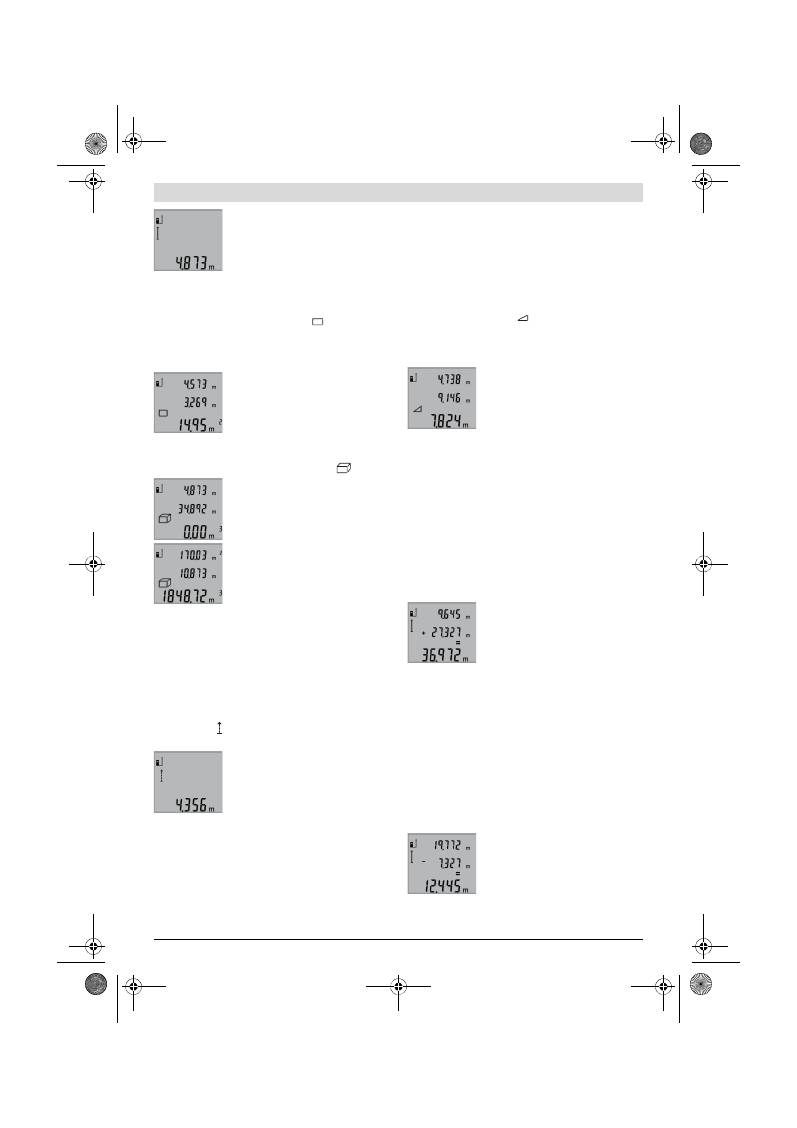
62
| Norsk
2 609 140 773 | (4.12.12)
Bosch Power Tools
Til innkopling av laseren og til måling tryk-
ker du en gang kort på måletasten
2
.
Måleverdien anvises i resultatlinje
b
.
Ved flere lengdemålinger etter hverandre
anvises resultatene for de siste målingene
i måleverdilinjene
a
.
Flatemåling (se bilde C)
Til flatemålinger trykker du så mange ganger på tasten
3
, til
displayet viser meldingen for flatemåling
.
Mål deretter lengde og bredde etter hverandre som for en
lengdemåling. Mellom de to målingene forblir laserstrålen inn-
koblet.
Etter avslutning av den andre målingen
beregnes flaten automatisk og vises i re-
sultatlinjen
b
. Enkeltmåleverdiene står i
måleverdilinjene
a
.
Volummåling (se bilde D)
Til volummålinger trykker du så mange ganger på tasten
3
, til
anvisningen for volummåling vises på displayet
.
Deretter måles lengde, bredde og høyde
etter hverandre som ved en lengdemå-
ling. Mellom de tre målingene forblir la-
serstrålen innkoblet.
Når den tredje målingen er avsluttet reg-
nes volumet automatisk ut og anvises i re-
sultatlinjen
b
. Enkeltmåleverdiene står i
måleverdilinjene
a
.
Verdier over 999999 m
3
kan ikke anvi-
ses, på displayet vises
«ERROR»
. Del vo-
lumet som skal måles opp i enkeltmålinger, der du beregner
verdiene enkeltvis og deretter sammenfatter dem.
Kontinuerlig måling (se bilde E)
Ved en kontinuerlig måling kan måleverktøyet beveges i for-
hold til målet og måleverdien aktualiseres da ca. hvert 0,5 s.
Du kan for eksempel gå bort fra en vegg til ønsket avstand,
den aktuelle avstanden kan alltid avleses.
Til kontinuerlige målinger trykker du på tasten
9
til displayet
viser meldingen for kontinuerlig måling. For å starte den
kontinuerlige målingen trykker du på tasten for måling
2
.
Den aktuelle måleverdien anvises i resul-
tatlinje
b
.
Ved å trykke på måletasten
2
avsluttes
den kontinuerlige målingen. Den siste
måleverdien anvises i resultatlinje
b
. Ved
å trykke på måletasten
2
en gang til star-
tes den kontinuerlige målingen igjen.
Den kontinuerlige målingen kobles automatisk ut etter 5 min.
Den siste måleverdien vises fortsatt i resultatlinje
b
.
Indirekte høydemåling / Enkel Pythagorasmåling
(se bilde F)
Den indirekte høydemålingen er til beregning av avstander
som ikke kan måles direkte, fordi en hindring kan innskrenke
strålingen eller det ikke finnes en målflate som reflektor. Kor-
rekte resultater oppnås kun når den nødvendige rette vinke-
len overholdes nøyaktig ved aktuelle målingen (Pythagoras-
læresetning).
Pass på at referansepunktet for målingen (f. eks. bakkanten
på måleverktøyet) er på nøyaktig samme sted ved alle enkelt-
målingene i en måling.
Mellom enkeltmålingene forblir laserstrålen innkoblet.
Trykk flere ganger på tasten
3
til meldingen for enkel Pythago-
rasmåling vises på displayet
.
Som ved en lengdemåling måler du strekningene
«1»
og
«2»
i
denne rekkefølgen. Pass på at det finnes en rett vinkel mellom
strekningen
«1»
og den søkte strekningen
«X»
.
Etter avslutning av den siste målingen an-
vises resultatet for den søkte strekningen
«X»
i resultatlinjen
b
. Enkeltmåleverdiene
står i måleverdilinjene
a
.
Sletting av måleverdier
Ved å trykke kort på tasten
4
kan du slette den siste enkeltmå-
leverdien i alle målefunksjonene. Ved flere gangers kort tryk-
king på tasten slettes enkeltmåleverdiene i omvendt rekkeføl-
ge.
Addering av måleverdier
Til addering av måleverdier utfører du først hvilken som helst
måling. Trykk så på plusstasten
8
. På displayet vises til be-
kreftelse
«+»
.
Til addering av volumer eller flater trykker du etter den første
avsluttede målingen på plusstasten
8
. På displayet vises til
bekreftelse
«+»
til venstre for volum-/flatesymbolet.
Utfør deretter en annen måling.
Til sjekking av summen på begge målinge-
ne trykker du gjen på plusstasten
8
. Be-
regningen anvises i måleverdilinjene
a
,
summen står i resultatlinjen
b
.
Etter beregning av summen kan det adde-
res ytterligere måleverdier, hvis plusstas-
ten
8
trykkes før målingen.
Informasjon om adderingen:
– Lengde-, flate- og volumverdier kan ikke adderes blandet.
Hvis det f. eks. adderes en lengde- og en flateverdi, vises
ved trykking av plusstasten
8
kort meldingen
«ERROR»
på
displayet. Deretter skifter måleverktøyet til siste aktive
målefunksjon.
– Det adderes alltid resultatet av en måling (f.eks. volumver-
di), ved kontinuerlige målinger måleverdien som anvises i
resultatlinjen
b
. Adderingen av enkeltmåleverdier fra må-
leverdilinjene
a
er ikke mulig.
Subtrahering av måleverdier
Til subtrahering av måleverdier trykker du
på minustasten
5
, på displayet vises til
bekreftelse
«–»
. Ytterligere fremgangs-
måte er analog til «Addering av måleverdi-
er».
OBJ_BUCH-1444-004.book Page 62 Tuesday, December 4, 2012 1:47 PM
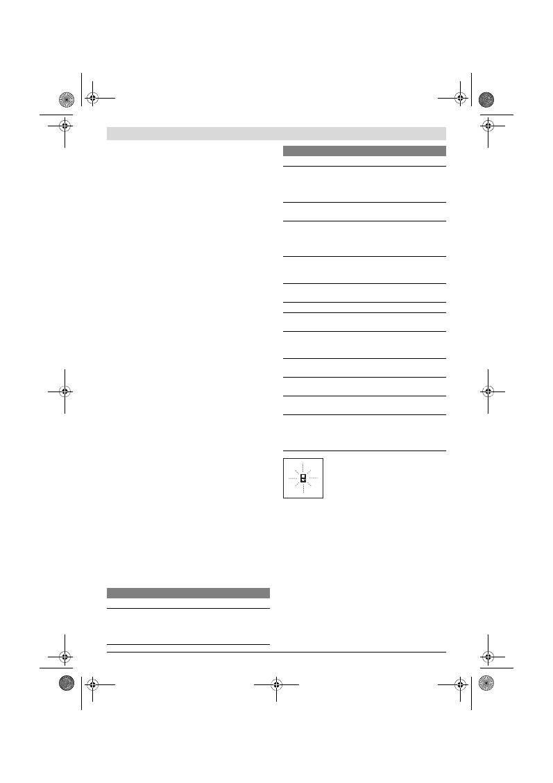
Norsk |
63
Bosch Power Tools
2 609 140 773 | (4.12.12)
Arbeidshenvisninger
Generelle informasjoner
Mottakerlinsen
12
og laserutgangen
11
må ikke være tildek-
ket under målingen.
Måleverktøyet må ikke beveges i løpet av en måling (med unn-
tak av funksjonen for kontinuerlig måling). Legg derfor måle-
verktøyet helst på en fast anslag- eller liggeflate.
Innflytelse på måleområdet
Måleområdet er avhengig av lysforholdene og refleksjonse-
genskapene til målflaten. For å kunne se laserstrålen bedre
ved utendørs arbeid og i sterk sol bør du bruke laser-beskyt-
telsesbrillene
19
(tilbehør) og laser-måltavlen
20
(tilbehør),
eller skygg for målflaten.
Innflytelser på måleresultatet
På grunn av fysikalske effekter kan det ikke utelukkes at det
oppstår feilmålinger ved måling av forskjellige overflater. Her-
til hører:
– transparente overflater (f.eks. glass, vann),
– speilende overflater (f.eks. polert metall, glass),
– porøse overflater (f.eks. isolasjonsmateriale),
– strukturerte overflater (f.eks. puss, naturstein).
Bruk eventuelt laser-måltavlen
20
(tilbehør) på disse overfla-
tene.
Feilmålinger er dessuten mulig på målflater det siktes på skrå
mot.
På samme måte kan luftsjikt med forskjellige temperaturer el-
ler indirekte mottatte refleksjoner påvirke måleresultatet.
Presisjonskontroll av avstandsmålingen
Du kan kontrollere avstandsmålingens nøyaktighet på følgen-
de måte:
– Velg en målestrekning på ca. 1 til 10 m (f. eks. rombredde,
døråpning) som ikke forandrer seg og som du kjenner den
nøyaktige lengden på. Målestrekningen må være innen-
dørs, målflaten for målingen må være glatt og godt reflek-
terende.
– Mål denne strekningen 10 ganger etter hverandre.
Avviket mellom enkeltmålingene og middelverdien må være
maksimalt ±2 mm. Protokoller målingene slik at nøyaktighe-
ten kan sammenlignes på et senere tidspunkt.
Arbeid med stativ (tilbehør)
Det er kun nødvendig å bruke stativ ved større avstander. Sett
måleverktøyet med 1/4"-gjengen
14
på hurtigskifteplaten til
stativet
18
eller et vanlig fotostativ. Skru det fast med feste-
skruen til hurtigskifteplaten.
Innstill referansenivået til måling med stativ ved å trykke på
tasten
6
(referansenivå gjenger).
Feil
–
Årsaker og utbedring
Måleverktøyet overvåker den korrekte
funksjonen ved hver måling. Hvis en defekt
finnes, blinker kun symbolet ved siden av
på displayet. I dette tilfellet – eller hvis de
ovennevnte tiltakene ikke kunne fjerne en
feil – må du levere måleverktøyet inn til et
Bosch-serviceverksted via forhandleren.
Service og vedlikehold
Vedlikehold og rengjøring
Måleverktøyet må kun lagres og transporteres i medlevert be-
skyttelsesvesken.
Hold måleverktøyet alltid rent.
Dypp aldri måleverktøyet i vann eller andre væsker.
Tørk smussen av med en fuktig, myk klut. Ikke bruk rengjø-
rings- eller løsemidler.
Stell spesielt mottakerlinsen
12
med samme omhu som bril-
ler eller linsen til et fotoapparat skal behandles med.
Årsak
Utbedring
Temperaturvarsel (f) blinker, måling er ikke mulig
Måleverktøyet er utenfor en drifts-
temperatur på – 10 °C til +50 °C
(i funksjonen for kontinuerlig må-
ling opp til +40 °C).
Vent til måleverktøyet
har nådd driftstempera-
turen
Melding «ERROR» på displayet
Addisjon/subtraksjon av målever-
dier med forskjellige målenheter
Det må kun adde-
res/subtraheres måle-
verdier med samme mål-
enheter
Vinkelen mellom laserstråle og mål
er for spiss.
Øk vinkelen mellom la-
serstråle og mål
Målflaten reflekterer for sterkt
(f.eks. speil) hhv. for svakt (f.eks.
sort stoff) eller omgivelseslyset er
for sterkt.
Bruk en laser-måltavle
20
(tilbehør)
Laserstråleutgangen
11
hhv. mot-
takerlinsen
12
er dugget (f.eks. på
grunn av hurtig temperaturskifte).
Tørk laserutgangen
11
hhv. mottakerlinsen
12
tørr med en myk klut
Beregnet verdi er større enn
999999 m/m
2
/m
3
.
Oppdeling av beregnin-
gen i mellomskritt
Ikke plausibelt måleresultat
Målflaten er ikke entydig (f.eks.
vann, glass).
Dekk til målflaten
Laserutgangen
11
hhv. mottaker-
linsen
12
er tildekket.
Hold laserutgangen
11
hhv. mottakerlinsen
12
fri
Galt referansenivå innstilt
Velg referansenivå som
passer til målingen
Hindring der laserstrålen går
Laserpunktet må treffe
komplett på målflaten.
Meldingen forblir uforandret eller måleverktøyet reage-
rer uventet på tastetrykk
Feil i programvaren
Ta ut batteriene og start
måleverktøyet igjen et-
ter å ha satt inn batterie-
ne på nytt.
Årsak
Utbedring
OBJ_BUCH-1444-004.book Page 63 Tuesday, December 4, 2012 1:47 PM
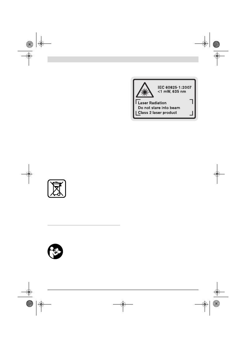
64
| Suomi
2 609 140 773 | (4.12.12)
Bosch Power Tools
Hvis måleverktøyet til tross for omhyggelige produksjons- og
kontrollmetoder en gang skulle svikte, må reparasjonen utfø-
res av et Bosch service-/garantiverksted. Du må ikke åpne
måleverktøyet selv.
Ved alle forespørsler og reservedelsbestillinger må du oppgi
det 10-sifrede produktnummeret som er angitt på måleverk-
tøyets typeskilt.
Send måleverktøyet inn til reparasjon i beskyttelsesvesken
17
.
Kundeservice og rådgivning ved bruk
Kundeservicen svarer på dine spørsmål om reparasjon og
vedlikehold av produktet samt om reservedeleler. Spreng-
skisser og informasjon om reservedeler finner du også på:
www.bosch-pt.com
Bosch rådgivningsteamet hjelper deg gjerne ved spørsmål an-
gående våre produkter og deres tilbehør.
Norsk
Robert Bosch AS
Postboks 350
1402 Ski
Tel.: 64 87 89 50
Faks: 64 87 89 55
Deponering
Måleverktøy, tilbehør og emballasje må leveres inn til miljø-
vennlig gjenvinning.
Måleverktøy og batterier må ikke kastes i vanlig søppel!
Kun for EU-land:
Iht. det europeiske direktivet 2002/96/EF
om ubrukelige måleapparater og iht. det eu-
ropeiske direktivet 2006/66/EF må defek-
te eller oppbrukte batterier/oppladbare
batterier samles inn adskilt og leveres inn til
en miljøvennlig resirkulering.
Rett til endringer forbeholdes.
Suomi
Turvallisuusohjeita
Kaikki ohjeet täytyy lukea ja noudattaa,
jotta voidaan työskennellä vaarattomasti
ja varmasti mittaustyökalun kanssa. Älä
koskaan peitä tai poista mittaustyökalussa
olevia varoituskilpiä. SÄILYTÄ NÄMÄ
OHJEET HYVIN.
Varoitus – jos käytetään muita, kuin tässä mainittuja
käyttö- tai säätölaitteita tahi menetellään eri tavalla,
saattaa tämä johtaa vaarallisen säteilyn altistukseen.
Mittaustyökalu toimitetaan varustettuna englannin-
kielisellä varoituskilvellä (grafiikkasivun mittaustyö-
kalun kuvassa merkitty numerolla 15).
Liimaa ennen ensimmäistä käyttöä toimitukseen kuu-
luva oman kielesi tarra englanninkielisen kilven päälle.
Älä koskaan suuntaa lasersädettä ihmisiin tai eläimiin,
älä myös itse katso lasersäteeseen.
Tämä mittaustyöka-
lu tuottaa laserluokan 2 lasersädettä IEC 60825-1 mu-
kaan. Täten voit tahattomasti sokaista ihmisiä.
Älä käytä lasertarkkailulaseja suojalaseina.
Lasertark-
kailulasien tarkoitus on erottaa lasersäde paremmin, ne ei-
vät kuitenkaan suojaa lasersäteeltä.
Älä käytä lasertarkkailulaseja aurinkolaseina tai tielii-
kenteessä.
Lasertarkkailulasit eivät anna täydellistä
UV-suojaa, ja ne alentavat värien erotuskykyä.
Anna ainoastaan koulutettujen ammattihenkilöiden
korjata mittaustyökalusi ja salli korjauksiin käytettä-
vän vain alkuperäisiä varaosia.
Täten varmistat, että mit-
taustyökalu säilyy turvallisena.
Älä anna lasten käyttää lasermittaustyökalua ilman
valvontaa.
He voivat tahattomasti sokaista ihmisiä.
Älä työskentele mittaustyökalulla räjähdysalttiissa
ympäristössä, jossa on palavaa nestettä, kaasua tai pö-
lyä.
Mittaustyökalussa voi muodostua kipinöitä, jotka saat-
tavat sytyttää pölyn tai höyryt.
Tuotekuvaus
Käännä auki taittosivu, jossa on mittaustyökalun kuva ja pidä
se uloskäännettynä lukiessasi käyttöohjetta.
Määräyksenmukainen käyttö
Mittaustyökalu on tarkoitettu etäisyyksien, pituuksien, korke-
uksien ja välimatkojen mittauksiin sekä pintojen ja tilavuuksi-
en laskemiseen. Mittaustyökalu soveltuu mittaukseen sisällä
ja ulkona.
OBJ_BUCH-1444-004.book Page 64 Tuesday, December 4, 2012 1:47 PM
Suomi |
65
Bosch Power Tools
2 609 140 773 | (4.12.12)
Tekniset tiedot
Kuvassa olevat osat
Kuvassa olevien osien numerointi viittaa grafiikkasivussa ole-
vaan mittaustyökalun kuvaan.
1
Näyttö
2
Mittausnäppäin
3
Pinta-ala-, tilavuus- ja epäsuora korkeusmittausnäppäin
(Pythagoras)
4
Muistin tyhjennysnäppäin / käynnistysnäppäin **
5
Miinusnäppäin
6
Vertailutason valintanäppäin
7
Kannatinsilmukan kiinnike
8
Plusnäppäin
9
Pituus- ja jatkuva mittausnäppäin
10
Paristokotelon kansi
11
Lasersäteen ulostuloaukko
12
Vastaanottolinssi
13
Sarjanumero
14
1/4"-kierre
15
Laservaroituskilpi
16
Paristokotelon kannen lukitus
17
Suojalaukku
18
Jalusta*
19
Lasertarkkailulasit*
20
Lasertähtäintaulu*
* Kuvassa tai selostuksessa esiintyvä lisätarvike ei kuulu vakiotoi-
mitukseen.
** Pidä näppäin painettuna lisätoimintojen kutsumiseksi.
Näyttöelementit
a
MIttausarvorivit
b
Tulosrivi
c
Mittaustoiminnot
Digitaalinen laseretäisyysmittalaite
GLM 50
Professional
Tuotenumero
3 601 K72 2..
Kantama
0,05 –50 m
A)
Mittaustarkkuus (tyypillinen)
±1,5 mm
B)
Pienin osoitettava yksikkö
1 mm
Käyttölämpötila
–10 °C...+50 °C
C)
Varastointilämpötila
–20 °C...+70 °C
Ilman suhteellinen kosteus maks.
90 %
Laserluokka
2
Lasertyyppi
635 nm, <1 mW
Lasersäteen halkaisija (lämpötilassa 25 °C) n.
– 10 m etäisyydellä
– 50 m etäisyydellä
6 mm
35 mm
Poiskytkentäautomatiikka n. kuluttua
– laser
– mittaustyökalu (ei mittausta)
20 s
5 min
Paristot
Ladattavat paristot
2 x 1,5 V LR03 (AAA)
2 x 1,2 V HR03 (AAA)
Parison kesto n.
– Yksittäismittaukset
– Jatkuva mittaus
10000
D)
2,5 h
D)
Paino vastaa EPTA-Procedure 01/2003
0,14 kg
Mitat
53 x 114 x 30 mm
Suojaus
IP 54 (pöly- ja roiskevesisuojattu)
A) Etäisyys kasvaa sitä enemmän mitä paremmin laservalo palautuu kohdepinnasta (hajavalona, ei heijastuksena) ja mitä kirkkaampana laserpiste erot-
tuu ympäristön valoista (sisätilat, himmennys). Epäsuotuisissa olosuhteissa (esim. mittaus ulkona voimakkaassa auringonpaisteessa) saattaa laser-
kohdetaulun käyttö olla välttämätön.
B) Kun mitataan mittaustyökalun takareunasta. Epäsuotuisissa olosuhteissa, kuten esim. voimakkaassa auringonpaisteessa tai huonosti heijastuvilla
pinnoilla on suurin poikkeama
±
10 mm 50 m matkalla. Suotuisissa olosuhteissa voi laskea vaikutuksen olevan
±
0,05 mm/m.
C) Toiminnossa jatkuva mittaus on suurin sallittu käyttölämpötila +40
°C
.
D) 1,2 V akulla ei pysty yhtä moneen mittaukseen kuin 1,5 V paristoilla. Paristojen mainittu kestoaika perustuu mittauksiin ilman näytön valaistusta.
Tyyppikilvessä oleva sarjanumero
13
mahdollistaa mittaustyökalun yksiselitteisen tunnistuksen.
OBJ_BUCH-1444-004.book Page 65 Tuesday, December 4, 2012 1:47 PM
66
| Suomi
2 609 140 773 | (4.12.12)
Bosch Power Tools
d
Laser kytketty
e
Mittauksen vertailutaso
f
Lämpötilavaroitus
g
Paristovaroitus
h
Vikanäyttö
”ERROR”
Asennus
Paristojen asennus/vaihto
Mittaustyökalun voimanlähteenä suosittelemme käyttämään
alkali-mangaani-paristoja tai akkukennoja.
1,2 V akuilla ei pysty yhtä moneen mittaukseen kuin 1,5 V pa-
ristoilla.
Avaa paristokotelon kansi
10
painamalla lukitusta
16
ja poista
kansi. Aseta paristot tai akkukennot paikoilleen. Varmista oi-
kea napaisuus paristokotelon sisällä olevan kuvan mukaisesti.
Ota paristoja tai akkukennoja asennettaessa huomioon oikea
napaisuus paristokotelossa olevan kuvan mukaisesti.
Kun paristotunnus
tulee ensimmäisen kerran näyttöön,
voidaan suorittaa vielä vähintään 100 mittausta. Jatkuva mit-
taustoiminto on deaktivoitu.
Paristomerkin
vilkkuessa tulee paristot vaihtaa. Mittauk-
set eivät enää ole mahdollisia.
Vaihda aina kaikki paristot tai akkukennot samanaikaisesti.
Käytä yksinomaan saman valmistajan saman tehoisia paristo-
ja tai akkukennoja.
Poista paristot tai akkukennot mittaustyökalusta, ellet
käytä sitä pitkään aikaan.
Paristot ja akkukennot saatta-
vat hapettua tai purkautua itsestään pitkäaikaisessa varas-
toinnissa.
Käyttö
Käyttöönotto
Älä jätä kytkettyä mittaustyökalua ilman valvontaa ja
sammuta mittaustyökalu käytön jälkeen.
Lasersäde
saattaa häikäistä muita henkilöitä.
Suojaa mittaustyökalu kosteudelta ja suoralta aurin-
gonvalolta.
Älä aseta mittaustyökalua alttiiksi äärimmäisille läm-
pötiloille tai lämpötilan vaihteluille.
Älä esim. jätä sitä
pitkäksi aikaa autoon. Anna suurten lämpötilavaihtelujen
jälkeen mittaustyökalun lämpötilan tasaantua, ennen kuin
käytät sitä. Äärimmäiset lämpötilat tai lämpötilavaihtelut
voivat vaikuttaa mittaustyökalun tarkkuuteen.
Vältä kovia iskuja tai mittaustyökalun pudottamista.
Jos mittaustyökaluun on vaikuttanut voimakkaita ulkoisia
voimia, tulisi ennen työn jatkamista suorittaa tarkkuustar-
kistus (katso ”Etäisyysmittauksen tarkkuuden tarkistus”,
sivu 68).
Käynnistys ja pysäytys
Mittaustyökalun
käynnistykseen
sinulla on seuraavat mah-
dollisuudet:
– Paina käynnistysnäppäintä
4
: mittaustyökalu käynnistyy ja
on toimintomuodossa pituusmittaus. Laser ei käynnisty.
– Paina mittausnäppäintä
2
: mittaustyökalu ja laser käynnis-
tyvät. Mittaustyökalu on toiminnossa pituusmittaus.
Älä koskaan suuntaa lasersädettä ihmisiin tai eläimiin,
älä myöskään itse katso lasersäteeseen edes kaukaa.
Pysäytä
mittalaite painamalla käynnistysnäppäintä
4
.
Jos n. 5 minuutin aikana ei paineta mitään mittalaitteen paini-
ketta, mittalaite sammuttaa itsensä automaattisesti pariston
säästämiseksi.
Mittaustapahtuma
Kun mittaustyökalu käynnistetään painamalla mittauspaini-
ketta
2
, mittaustyökalu on aina toimintomuodossa pituusmit-
taus. Muut mittaustoiminnot valitset painamalla kyseistä toi-
mintonäppäintä (katso ”Mittaustoiminnot”, sivu 67).
Mittaustyökalun takareuna asettuu mittauksen vertailutasoksi
käynnistyksen jälkeen. Painamalla vertailupintanäppäintä
6
voit muuttaa vertailutason (katso ”Vertailutason valinta”,
sivu 66).
Aseta mittaustyökalun valittu vertailutaso mittauksen halut-
tuun lähtöpisteeseen (esim. seinä).
Käynnistä lasersäde painamalla mittausnäppäintä
2
lyhyesti.
Älä koskaan suuntaa lasersädettä ihmisiin tai eläimiin,
älä myöskään itse katso lasersäteeseen edes kaukaa.
Tähtää kohdepintaa lasersäteellä. Käynnistä mittaus paina-
malla mittausnäppäintä
2
lyhyesti uudelleen.
Jatkuvamittaus-toiminnossa mittaus käynnistyy heti toimin-
toa kytkettäessä.
Mittausarvo ilmestyy 0,5 s aikana ja viimeistään 4 s kuluttua.
Mittauksen kesto riippuu etäisyydestä, valaistusolosuhteista
ja mittauspinnan heijastusominaisuuksista. Lasersäde sam-
muu automaattisesti mittauksen jälkeen.
Noin 20 s kuluttua ilman mittausta kytkeytyy mittauslaite au-
tomaattisesti pois pariston säästämiseksi.
Vertailutason valinta (katso kuva A)
Voit mittausta varten valita kolmesta eri vertailutasosta:
– mittaustyökalun takareuna (esim. seinäpinnasta mitatta-
essa),
– mittaustyökalun etureuna (esim. pöydän reunasta mitatta-
essa),
– kierteen keskiosa
14
(esim. jalustan kanssa mitattaessa),
Valitse vertailutaso painamalla toistuvasti näppäintä
6
, kun-
nes haluttu vertailutaso näkyy näytössä. Jokaisen käynnistyk-
sen jälkeen mittaustyökalun takareuna toimii oletusvertailu-
tasona.
Pituusmittaus
Jatkuva mittaus
Pinta-alamittaus
Tilavuusmittaus
Yksinkertainen Pythagoramittaus
OBJ_BUCH-1444-004.book Page 66 Tuesday, December 4, 2012 1:47 PM
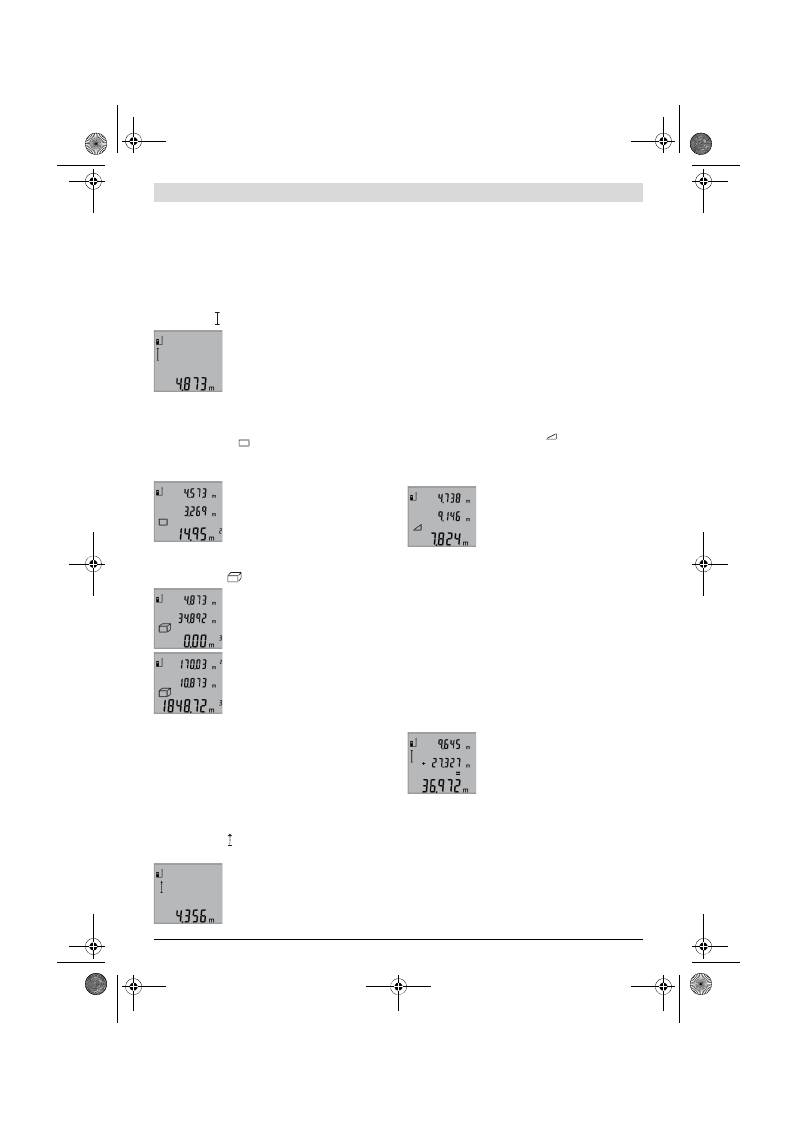
Suomi |
67
Bosch Power Tools
2 609 140 773 | (4.12.12)
Näytön valaistus
Näytön valaistus aktivoituu automaattisesti ympäristön valoi-
suuden mukaan. Jos näytön valaistuksen kytkennän jälkeen ei
näppäimiä paineta, se himmenee paristojen säästämiseksi.
Mittaustoiminnot
Yksinkertainen pituusmittaus (katso kuva B)
Paina pituusmittausta varten näppäintä
9
, kunnes pituusmit-
tauksen merkki ilmestyy näyttöön.
Paina mittausnäppäintä
2
kerran lyhyesti
laserin käynnistystä ja mittausta varten.
Mittausarvo näkyy tulosrivillä
b
.
Monen peräkkäisen pituusmittauksen ai-
kana näkyy viimeisten mittausten tulok-
set mittausarvoriveissä
a
.
Pinta-alamittaus (katso kuva C)
Paina pinta-alamittausta varten näppäintä
3
, kunnes pinta-
alamittauksen merkki
ilmestyy näyttöön.
Mittaa ensin pituus ja leveys peräkkäin, kuten pituusmittauk-
sessa. Lasersäde pysyy kytkettynä kahden mittauksen välillä.
Toisen loppuunviedyn mittauksen jälkeen
laskee laite automaattisesti pinta-alan ja
osoittaa sen tulosrivillä
b
. Yksittäismit-
tausarvot näkyvät mittausarvoriveillä
a
.
Tilavuusmittaus (katso kuva D)
Paina tilavuusmittausta varten näppäintä
3
, kunnes tilavuus-
mittauksen merkki
ilmestyy näyttöön.
Mittaa ensin pituus, leveys ja korkeus pe-
räkkäin, kuten pituusmittauksessa. La-
sersäde pysyy kytkettynä kolmen mitta-
uksen välillä.
Kolmannen loppuunviedyn mittauksen
jälkeen laskee laite automaattisesti tila-
vuuden ja osoittaa sen tulosrivillä
b
. Yksit-
täismittausarvot näkyvät mittausarvori-
veillä
a
.
999999 m
3
suurempia arvoja ei voida näyttää, näyttöön syt-
tyy
”ERROR”
. Jaa mitattava tilavuus yksittäismittauksiin, joi-
den arvo lasketaan erikseen ja sen jälkeen yhdistetään.
Jatkuva mittaus (katso kuva E)
Jatkuvassa mittauksessa voidaan mittaustyökalua siirtää suh-
teessa kohteeseen, jolloin mittausarvo päivittyy 0,5 s välein.
Voit esimerkiksi siirtyä seinästä poispäin haluttuun etäisyy-
teen saakka, todellinen etäisyys on jatkuvasti luettavissa.
Paina jatkuvaa mittausta varten näppäintä
9
, kunnes jatkuvan
mittauksen merkki ilmestyy näyttöön. Käynnistä jatkuva
mittaus painamalla mittausnäppäintä
2
.
Kyseinen mittausarvo näkyy tulosrivillä
b
.
Painamalla mittausnäppäintä
2
keskeytät
jatkuvan mittauksen. Viimeisin mittausar-
vo näkyy tulosrivillä
b
. Mittausnäppäimen
2
uusi painallus
aloittaa jatkuvan mittauksen alusta.
Jatkuva mittaus kytkee automaattisesti pois 5 min kuluttua.
Viimeisin mittausarvo jää näkyviin tulosriville
b
.
Epäsuora korkeusmittaus / Yksinkertainen Pythagoramit-
taus (katso kuva F)
Epäsuoran korkeusmittauksen tarkoitus on sellaisten etäi-
syyksien mittaaminen, joita ei voida mitata suoraan, koska sä-
teiden edessä on este tai säteen heijastuksen tarvitsema koh-
depinta puuttuu. Oikeat tulokset saavutetaan vain, jos
kussakin mittauksessa muodostetaan vaadittu suora kulma
(Pythagoran lauseke).
Varmista, että mittauksen vertailupiste (esim. mittaustyöka-
lun takareuna) on täsmälleen samassa kohdassa kaikissa yh-
den mittaustapahtuman yksittäismittauksissa.
Lasersäde pysyy kytkettynä yksittäismittausten välillä.
Paina toiminnon näppäintä
3
niin monta kertaa, että yksinker-
taisen Pythagoramittauksen merkki
ilmestyy näyttöön.
Mittaa kuten pituusmittauksessa matkat
”1”
ja
”2”
tässä jär-
jestyksessä. Varmista, että matka
”1”
ja etsitty matka
”X”
muodostavat suoran kulman.
Viimeisen loppuunviedyn mittauksen jäl-
keen osoitetaan haetun matkan
”X”
tulos
tulosrivillä
b
. Yksittäismittausarvot näky-
vät mittausarvoriveillä
a
.
Mittausarvon poistaminen
Painamalla näppäintä
4
voit kaikissa mittaustoiminnoissa
poistaa viimeisenä mitatun yksittäisarvon. Jos painat näp-
päintä toistuvasti poistuvat yksittäisarvot käänteisessä järjes-
tyksessä.
Mittausarvojen yhteenlasku
Laske mittausarvoja yhteen suorittamalla ensin mielivaltainen
mittaus. Paina sitten plusnäppäintä
8
. Näyttöruutuun tulee
vahvistus
”+”
.
Tilavuuksien tai pinta-alojen yhteenlaskua varten, paina en-
simmäisen loppuun viedyn mittausvaiheen jälkeen pluspaini-
ketta
8
. Näyttöruutuun tulee vahvistus
”+”
tilavuus-/pinta-
alatunnuksen vasemmalle puolelle.
Suorita sitten toinen mittaus.
Tulosta kahden mittauksen summa paina-
malla plusnäppäintä
8
vielä kerran. Las-
kenta näytetään mittausarvoriveillä
a
,
summa on tulosrivillä
b
.
Summan laskennan jälkeen voit lisätä tä-
hän tulokseen muita mittausarvoja, pai-
namalla aina ennen mittausta ensin plusnäppäintä
8
.
Yhteenlaskuohjeita:
– Pituus-, pinta-ala ja tilavuusarvoja ei voida laskea sekaisin
yhteen. Jos esimerkiksi lasketaan yhteen pituus- ja pinta-
ala-arvo, tulee näyttöön hetkeksi
”ERROR”
, kun plusnäp-
päintä
8
painetaan. Sen jälkeen mittaustyökalu vaihtaa vii-
meisimpänä käytettyyn mittaustoimintoon.
– Mittauksen kulloinenkin tulos (esim. tilavuusarvo) laske-
taan yhteen, jatkuvassa mittauksessa tulosrivillä
b
näytet-
OBJ_BUCH-1444-004.book Page 67 Tuesday, December 4, 2012 1:47 PM
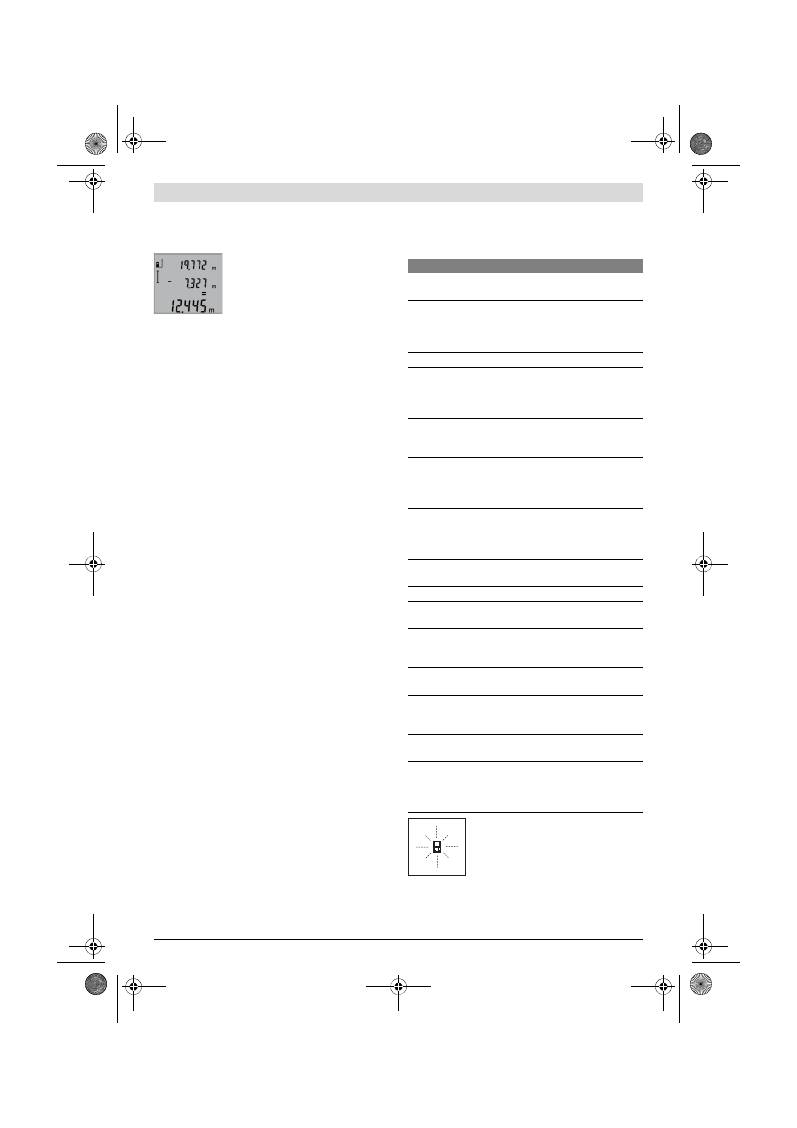
68
| Suomi
2 609 140 773 | (4.12.12)
Bosch Power Tools
ty mittausarvo. Yksittäisten mittausarvojen yhteenlasku
mittausarvoriveiltä
a
ei ole mahdollista.
Mittausarvojen vähennyslasku
Mittausarvojen vähennyslaskua varten
painat miinusnäppäintä
5
, näytössä nä-
kyy vahvistus
”–”
. Muu menettely on sa-
manlainen, kuin ”Mittausarvojen yhteen-
lasku”.
Työskentelyohjeita
Yleisiä ohjeita
Vastaanottolinssi
12
tai lasersäteen ulostuloaukko
11
ei saa
olla peitettynä mittauksen aikana.
Mittaustyökalua ei saa liikuttaa mittauksen aikana (poikkeuk-
sena jatkuva mittaustoiminto). Aseta siksi mittaustyökalu
mahdollisuuksien mukaan kiinteää vastetta tai tukipintaa vas-
ten.
Mittausalueeseen vaikuttavat tekijät
Mittausalue riippuu valaistusolosuhteista ja kohdepinnan hei-
jastusominaisuuksista. Käytä lasersäteen paremman näky-
vyyden aikaansaamiseksi ulkotilassa ja voimakkaassa aurin-
gonpaisteessa lasertarkkailulaseja
19
(lisätarvike) ja
laserkohdetaulua
20
(lisätarvike), tai varjosta kohdepintaa.
Mittaustulokseen vaikuttavat tekijät
Fysikaalisista vaikutuksista johtuen ei voida sulkea pois mah-
dollisuutta, että erilaiset pinnat saattavat johtaa mittausvir-
heisiin. Näihin kuuluvat:
– läpinäkyvät pinnat (esim. lasi, vesi),
– heijastavat pinnat (esim. kiillotettu metalli, lasi),
– huokoiset pinnat (esim. eristysaineet),
– muotoillut pinnat (esim. roiskerappaus, luonnonkivi).
Käytä tarvittaessa näissä pinnoissa laserkohdetaulua
20
(lisä-
tarvike).
Mittausvirheet ovat lisäksi mahdollisia vinosti tähdätyissä
kohdepinnoissa.
Samoin voivat erilämpöiset ilmakerrokset tai epäsuoraan vas-
taanotetut heijasteet vaikuttaa mittausarvoon.
Etäisyysmittauksen tarkkuuden tarkistus
Voit tarkistaa etäisyysmittauksen tarkkuuden seuraavalla ta-
valla:
– Valitse pysyvästi muuttumaton mittausmatka väliltä 1 …
10 m, jonka mitan tiedät täsmälleen (esim. huoneen leve-
ys, ovenaukko). Mittausmatkan on oltava sisätilassa, mit-
tauksen kohdepinnan tulee olla sileä ja hyvin heijastava.
– Mittaa tämä matka 10 kertaa peräkkäin.
Yksittäismittausten poikkeama keskiarvosta saa olla korkein-
taan ±2 mm. Tee mittauksista pöytäkirja, jotta myöhemmin
voit vertailla tarkkuutta.
Työskentely jalustan kanssa (lisätarvike)
Jalustan käyttö on välttämätöntä erityisesti suuremmilla etäi-
syyksillä. Mittaustyökalu voidaan kiinnittää jalustan
18
pika-
vaihtolevyn 1/4" kierteestään
14
yleismalliseen valokuvaus-
jalustaan. Ruuvaa kiinni se pikavaihtolevyn lukitusruuvilla.
Aseta vertailutaso mittauksille jalustan kanssa ja paina näp-
päintä
6
(vertailutasona kierre).
Viat
–
Syyt ja korjaus
Mittaustyökalu valvoo toiminnan oikeelli-
suutta jokaisen mittauksen yhteydessä. Jos
vika todetaan, näytössä vilkkuu vain vierei-
nen tunnusmerkki. Tässä tapauksessa tai,
jos ylläesitetyt korjaustoimenpiteet eivät
poistaneet vikaa, tulee mittaustyökalu toi-
mittaa myyjäliikkeen kautta Bosch asiakaspalveluun.
Syy
Korjaus
Lämpötilavaroitus (f) vilkkuu, mittausta ei voida suorit-
taa
Mittaustyökalu on käyttölämpöti-
la- alueen – 10 °C ... +50 °C ulko-
puolella (jatkuvassa mittauksessa
+40 °C asti).
Odota, kunnes mittaus-
työkalu on saavuttanut
käyttölämpötilan
Osoitus ”ERROR” näytössä
Eri mittasuureiden mittausarvojen
yhteenlasku tai vähennys
Käytä yhteenlasua/vä-
hennystä vain saman-
suureisilla mittayksiköil-
lä
Lasersäteen ja kohdepinnan väli-
nen kulma on liian terävä.
Suurenna lasersäteen ja
kohdepinnan välinen
kulma
Kohdepinta heijastaa liian voimak-
kaasti (esim. peili) tai liian heikosti
(esim. musta kangas) tahi ympä-
ristön valo on liian kirkas.
Käytä laserkohdetaulua
20
(lisätarvike)
Lasersäteen ulostuloaukko
11
tai
vastaanottolinssi
12
on huuruinen
(esim. nopean lämpötilanmuutok-
sen johdosta).
Kuivaa lasersäteen ulos-
tuloaukko
11
tai vas-
taanottolinssi
12
peh-
meällä kankaalla
Laskettu arvo on suurempi kuin
999999 m/m
2
/m
3
.
Jaa laskenta väliportai-
siin
Mittaustulos on epäjohdonmukainen
Kohdepinta ei heijasta yksiselittei-
sesti (esim. vesi, lasi).
Peitä kohdepinta
Lasersäteen ulostuloaukko
11
tai
vastaanottolinssi
12
on peitetty.
Pidä lasersäteen ulostu-
loaukko
11
ja vastaanot-
tolinssi
12
vapaana
Asetettu väärä vertailutaso
Valitse mittaukseen so-
piva vertailutaso
Lasersäteen edessä este
Laserpisteen on oltava
kokonaan kohdepinnas-
sa.
Näyttö pysyy muuttumattomana tai mittaustyökalu rea-
goi odottamattomalla tavalla näppäilyyn
Ohjelmavika
Poista paristot ja käyn-
nistä mittaustyökalu uu-
delleen asetettuasi pa-
ristot takaisin.
OBJ_BUCH-1444-004.book Page 68 Tuesday, December 4, 2012 1:47 PM
Ελληνικά |
69
Bosch Power Tools
2 609 140 773 | (4.12.12)
Hoito ja huolto
Huolto ja puhdistus
Säilytä ja kuljeta mittauslaite vain toimitukseen kuuluvassa
suojataskussa.
Pidä aina mittaustyökalu puhtaana.
Älä koskaan upota mittaustyökalua veteen tai muihin nestei-
siin.
Pyyhi pois lika kostealla pehmeällä rievulla. Älä käytä puhdis-
tusaineita tai liuottimia.
Käsittele erityisesti vastaanottolinssiä
12
samalla huolella
kuin silmälasia ja kameraa.
Jos mittaustyökalussa huolellisesta valmistuksesta ja koes-
tusmenettelystä huolimatta esiintyy vikaa, tulee korjaus antaa
Bosch-huollon tehtäväksi. Älä itse avaa mittaustyökalua.
Ilmoita ehdottomasti kaikissa kyselyissä ja varaosatilauksissa
10-numeroinen tuotenumero, joka löytyy mittaustyökalun
tyyppikilvestä.
Lähetä korjaustapauksessa mittaustyökalu suojalaukussa
17
korjattavaksi.
Asiakaspalvelu ja käyttöneuvonta
Asiakaspalvelu vastaa tuotteesi korjausta ja huoltoa sekä va-
raosia koskeviin kysymyksiin. Räjähdyspiirustuksia ja tietoja
varaosista löydät myös osoitteesta:
www.bosch-pt.com
Boschin käyttöneuvontatiimi auttaa mielellään sinua tuottei-
tamme ja niiden lisätarvikkeita koskevissa kysymyksissä.
Suomi
Robert Bosch Oy
Bosch-keskushuolto
Pakkalantie 21 A
01510 Vantaa
Puh.: 0800 98044
Faksi: 010 296 1838
www.bosch.fi
Hävitys
Toimita mittaustyökalut, lisätarvikkeet ja pakkausmateriaali
ympäristöystävälliseen kierrätykseen.
Älä heitä mittaustyökaluja tai akkuja/paristoja talousjätteisiin!
Vain EU-maita varten:
Eurooppalaisen direktiivin 2002/96/EY
mukaan käyttökelvottomat mittaustyökalut
ja eurooppalaisen direktiivin 2006/66/EY
mukaan vialliset tai loppuun käytetyt
akut/paristot täytyy kerätä erikseen ja toi-
mittaa ympäristöystävälliseen kierrätyk-
seen.
Oikeus teknisiin muutoksiin pidätetään.
Ελληνικά
Υποδείξεις ασφαλείας
Πρέπει να διαβάσετε και να τηρείτε όλες τις
οδηγίες για να μπορείτε να εργάζεστε με το
εργαλείο μέτρησης ακίνδυνα και ασφαλώς.
Μην σβήσετε ποτέ τις προειδοποιητικές πι-
νακίδες επάνω στο εργαλείο μέτρησης. ΔΙ-
ΑΦΥΛΑΞΕΤΕ ΚΑΛΑ ΑΥΤΈΣ ΤΙΣ ΟΔΗΓΙΕΣ.
Προσοχή – όταν εφαρμοστούν διαφορετικές διατάξεις
χειρισμού και ρύθμισης ή ακολουθηθούν διαφορετικές
διαδικασίες απ’ αυτές που αναφέρονται εδώ: αυτό μπο-
ρεί να οδηγήσει σε έκθεση σε επικίνδυνη ακτινοβολία.
Το εργαλείο μέτρησης παραδίνεται μαζί με μια προειδο-
ποιητική πινακίδα στην αγγλική γλώσσα (στην απεικόνι-
ση του οργάνου μέτρησης στη σελίδα με τα γραφικά χα-
ρακτηρίζεται με τον αριθμό 15).
Πριν την πρώτη εκκίνηση κολλήστε επάνω στην πινακί-
δα με την αγγλική γλώσσα την πινακίδα με τη γλώσσα
της χώρας σας.
Μην κατευθύνετε την ακτίνα λέιζερ επάνω σε πρόσωπα
ή ζώα και μην κοιτάζετε ο ίδιος/ή ίδια κατευθείαν στην
ακτίνα.
Αυτό το εργαλείο μέτρησης παράγει ακτινοβολία
λέιζερ κλάσης λέιζερ 2 κατά IEC 60825-1. Έτσι μπορεί να
τυφλώσετε άλλα πρόσωπα.
Μη χρησιμοποιήσετε τα γυαλιά παρατήρησης λέιζερ σαν
προστατευτικά γυαλιά.
Τα γυαλιά παρατήρησης λέιζερ χρη-
σιμεύουν για την καλύτερη αναγνώριση της ακτίνας λέιζερ
χωρίς, όμως, να προστατεύουν από την ακτινοβολία λέιζερ.
Μη χρησιμοποιείτε τα γυαλιά παρατήρησης λέιζερ σα γυ-
αλιά ηλίου ή στην οδική κυκλοφορία.
Τα γυαλιά παρα-
τήρησης λέιζερ δεν προστατεύουν επαρκώς από την υπεριώ-
δη ακτινοβολία (UV) και μειώνουν την αναγνώριση των χρω-
μάτων.
Να δίνετε το εργαλείο μέτρησης για επισκευή οπωσδή-
ποτε σε κατάλληλα εκπαιδευμένο προσωπικό και μόνο
με γνήσια ανταλλακτικά.
Μ’ αυτόν τον τρόπο εξασφαλί-
ζεται η διατήρηση της ασφαλούς λειτουργίας του εργαλείου
μέτρησης.
Μην αφήνετε παιδιά να χρησιμοποιούν ανεπιτήρητα το
εργαλείο μέτρησης.
Μπορεί, χωρίς να το θέλουν, να τυ-
φλώσουν άλλα πρόσωπα.
OBJ_BUCH-1444-004.book Page 69 Tuesday, December 4, 2012 1:47 PM
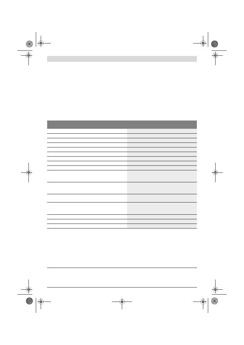
70
| Ελληνικά
2 609 140 773 | (4.12.12)
Bosch Power Tools
Να μην εργάζεστε με το εργαλείο μέτρησης σε περιβάλ-
λον στο οποίο υπάρχει κίνδυνος έκρηξης, ή στο οποίο
βρίσκονται εύφλεκτα υγρά, αέρια ή σκόνες.
Στο εσωτερι-
κό του εργαλείου μέτρησης μπορεί να δημιουργηθεί σπινθη-
ρισμός κι έτσι να αναφλεχθούν η σκόνη ή οι αναθυμιάσεις.
Περιγραφή του προϊόντος και της ισχύ-
ος του
Παρακαλούμε ξεδιπλώστε το διπλό εξώφυλλο με την απεικό-
νιση του εργαλείου μέτρησης κι αφήστε το ξεδιπλωμένο κατά τη
διάρκεια της ανάγνωσης των οδηγιών χειρισμού.
Χρήση σύμφωνα με τον προορισμό
Το εργαλείο μέτρησης προορίζεται για τη μέτρηση αποστάσε-
ων, μηκών, υψών και διαστημάτων καθώς και για τον υπολογι-
σμό επιφανειών και όγκων. Είναι κατάλληλο για μετρήσεις και
σε εσωτερικούς και σε εξωτερικούς χώρους.
Τεχνικά χαρακτηριστικά
Ψηφιακός μετρητής αποστάσεων λέιζερ
GLM 50
Professional
Αριθμός ευρετηρίου
3 601 K72 2..
Περιοχή μέτρησης
0,05 –50 m
A)
Ακρίβεια μέτρησης (χαρακτηριστική)
±1,5 mm
B)
Ελάχιστη μονάδα ένδειξης
1 mm
Θερμοκρασία λειτουργίας
–10 °C...+50 °C
C)
Θερμοκρασία διαφύλαξης/αποθήκευσης
–20 °C...+70 °C
Μέγ. σχετική υγρασία ατμόσφαιρας
90 %
Κατηγορία λέιζερ
2
Τύπος λέιζερ
635 nm, <1 mW
Διάμετρος ακτίνας λέιζερ (σε 25 °C) περίπου
– σε απόσταση 10 m
– σε απόσταση 50 m
6 mm
35 mm
Αυτόματη απόζευξη μετά από περίπου
– Λέιζερ
– Εργαλείο μέτρησης (χωρίς μέτρηση)
20 s
5 min
Μπαταρίες
Επαναφορτιζόμενα στοιχεία
2 x 1,5 V LR03 (AAA)
2 x 1,2 V HR03 (AAA)
Διάρκεια ζωής μπαταρίας περίπου
– Μεμονωμένες μετρήσεις
– Διαρκής μέτρηση
10000
D)
2,5 h
D)
Βάρος σύμφωνα με EPTA-Procedure 01/2003
0,14 kg
Διαστάσεις
53 x 114 x 30 mm
Βαθμός προστασίας
IP 54 (προστασία από σκόνη και ψεκασμό με νερό)
A) Η εμβέλεια αυξάνεται όσο καλύτερα επιστρέφει το φως λέιζερ από την επιφάνεια του στόχου (σκέδαση, όχι ανάκλαση) καθώς και όσο πιο φωτεινό είναι
το σημείο λέιζερ σε σχέση με τη φωτεινότητα του περιβάλλοντος (εσωτερικοί χώροι, ημίφως). Υπό δυσμενείς συνθήκες (π.χ. μέτρηση σε εξωτερικούς χώ-
ρους υπό ισχυρή ηλιακή ακτινοβολία) μπορεί να χρειαστεί να χρησιμοποιήσετε τον πίνακα στόχευσης.
B) Σε μετρήσεις από την πίσω ακμή του εργαλείου μέτρησης. Υπό δυσμενείς συνθήκες φωτισμού, π. χ. υπό ισχυρή ηλιακή ακτινοβολία, ή σε ανεπαρκώς ανα-
κλαστικές επιφάνειες η απόκλιση ανέρχεται σε
±
10 mm στα 50 m. Υπό ευνοϊκές συνθήκες πρέπει να υπολογίζετε με απόκλιση
±
0,05 mm/m.
C) Στη λειτουργία Διαρκής μέτρηση η μέγιστη θερμοκρασία λειτουργίας ανέρχεται σε +40
°C
.
D) Με μπαταρίες 1,2 V είναι εφικτές λιγότερες μετρήσεις απ’ όσο με μπαταρίες 1,5 V. Η αναφερόμενη διάρκεια λειτουργίας των μπαταριών βασίζεται σε
μετρήσεις χωρίς φωτισμό οθόνης.
Ο αριθμός σειράς
13
στην πινακίδα του κατασκευαστή χρησιμεύει για τη σαφή αναγνώριση του δικού σας εργαλείου μέτρησης.
OBJ_BUCH-1444-004.book Page 70 Tuesday, December 4, 2012 1:47 PM

Ελληνικά |
71
Bosch Power Tools
2 609 140 773 | (4.12.12)
Απεικονιζόμενα στοιχεία
Η απαρίθμηση των απεικονιζόμενων στοιχείων βασίζεται στην
απεικόνιση του εργαλείου μέτρησης στη σελίδα γραφικών.
1
Οθόνη
2
Πλήκτρο Μέτρηση
3
Πλήκτρο για μέτρηση επιφανειών, όγκων καθώς και για
έμμεση μέτρηση υψών (Θεώρημα του Πυθαγόρα)
4
Πλήκτρο διαγραφής / Πλήκτρο ON/OFF **
5
Πλήκτρο αφαίρεσης
6
Πλήκτρο επιλογής επιπέδου αναφοράς
7
Υποδοχή Κορδονιού μεταφοράς
8
Πλήκτρο άθροισης
9
Πλήκτρο μέτρησης μηκών και διαρκούς μέτρησης
10
Καπάκι θήκης μπαταρίας
11
Έξοδος ακτίνας λέιζερ
12
Φακός λήψης
13
Αριθμός σειράς
14
Σπείρωμα 1/4"
15
Προειδοποιητική πινακίδα λέιζερ
16
Ασφάλεια του καπακιού θήκης μπαταρίας
17
Τσάντα προστασίας
18
Τρίποδο*
19
Γυαλιά παρατήρησης λέιζερ*
20
Πίνακας στόχευσης λέιζερ*
* Εξαρτήματα που απεικονίζονται ή περιγράφονται δεν περιέχονται
στη στάνταρ συσκευασία.
** Για την κλήση περισσότερων λειτουργιών κρατήστε το πλήκτρο
πατημένο.
Στοιχεία ένδειξης
a
Γραμμές τιμών μέτρησης
b
Γραμμή αποτελεσμάτων
c
Λειτουργίες μέτρησης
d
Ενεργό λέιζερ
e
Επίπεδο αναφοράς της μέτρησης
f
Ένδειξη θερμοκρασίας
g
Προειδοποίηση μπαταρίας
h
Ένδειξη σφάλματος
«ERROR»
Συναρμολόγηση
Τοποθέτηση/αντικατάσταση
–
μπαταριών
Για τη λειτουργία του εργαλείου μέτρησης προτείνεται η χρήση
μπαταριών αλκαλίου-μαγγανίου ή επαναφορτιζόμενων μπατα-
ριών.
Με επαναφορτιζόμενες μπαταρίες 1,2 V είναι εφικτές λιγότε-
ρες μετρήσεις παρά με μπαταρίες 1,5 V.
Για να ανοίξετε το καπάκι της θήκης μπαταρίας
10
πατήστε την
ασφάλεια
16
και αφαιρέστε το καπάκι της θήκης μπαταρίας. Το-
ποθετήστε τις μπαταρίες. Προσέξτε, οι μπαταρίες να τοποθετη-
θούν με τη σωστή πολικότητα, σύμφωνα με την εικόνα στο εσω-
τερικό της θήκης μπαταρίας.
Όταν τοποθετείτε τις μπαταρίες να δίνετε προσοχή στη σωστή
πολικότητα, σύμφωνα με την εικόνα στη θήκη μπαταρίας.
Μόλις εμφανιστεί το σύμβολο μπαταρίας
για πρώτη φορά
στην οθόνη, τότε μπορείτε να διεξάγετε τουλάχιστο 100 μετρή-
σεις. Η λειτουργία για τη διαρκή μέτρηση είναι απενεργοποιη-
μένη.
Όταν το σύμβολο μπαταρίας
αναβοσβήνει, δεν μπορείτε να
μετρήσετε πλέον και πρέπει να αλλάξετε τις μπαταρίες. Δεν
μπορείτε πλέον να μετρήσετε.
Να αλλάζετε όλες τις μπαταρίες ταυτόχρονα. Οι μπαταρίες πρέ-
πει να είναι όλες από τον ίδιο κατασκευαστή και να έχουν την
ίδια χωρητικότητα.
Να βγάζετε τις μπαταρίες από το εργαλείο μέτρησης
όταν δεν πρόκειται να το χρησιμοποιήσετε για αρκετό
καιρό.
Σε περίπτωση μακρόχρονης αποθήκευσης οι μπατα-
ρίες μπορεί να σκουριάσουν και να αυτοεκφορτιστούν.
Λειτουργία
Θέση σε λειτουργία
Μην αφήνετε το ενεργοποιημένο εργαλείο μέτρησης
ανεπιτήρητο αλλά να το θέτετε μετά τη χρήση του εκτός
λειτουργίας.
Μπορεί να τυφλωθούν άλλα άτομα από την
ακτίνα λέιζερ.
Προστατεύετε το εργαλείο μέτρησης από υγρασία κι από
άμεση ηλιακή ακτινοβολία.
Να μην εκθέτετε το εργαλείο μέτρησης σε ακραίες θερ-
μοκρασίες και/ή σε ισχυρές διακυμάνσεις θερμοκρασί-
ας.
Για παράδειγμα, να μην το αφήνετε για πολλή ώρα στο
αυτοκίνητο. Σε περιπτώσεις ισχυρών διακυμάνσεων της θερ-
μοκρασίας πρέπει να περιμένετε να σταθεροποιηθεί πρώτα
η θερμοκρασία του εργαλείου μέτρησης πριν το χρησιμοποι-
ήσετε. Η ακρίβεια του εργαλείου μέτρησης μπορεί να αλλοι-
ωθεί υπό ακραίες θερμοκρασίες ή/και ισχυρές διακυμάνσεις
της θερμοκρασίας.
Να αποφεύγετε τις ισχυρές προσκρούσεις και τις πτώ-
σεις του εργαλείου μέτρησης.
Μετά από τυχόν ισχυρές
εξωτερικές επιδράσεις στο εργαλείο μέτρησης θα πρέπει,
πριν συνεχίσετε την εργασία σας, να διεξάγετε έλεγχο της
ακρίβειας (βλέπε «Έλεγχος ακρίβειας και της μέτρησης από-
στασης», σελίδα 74).
Θέση σε λειτουργία κι εκτός λειτουργίας
Για να
θέσετε σε λειτουργία
το εργαλείο μέτρησης μπορείτε
να επιλέξετε έναν από τους εξής τρόπους:
– Πατήστε το πλήκτρο ON/OFF
4
: Το εργαλείο μέτρησης ενερ-
γοποιείται και βρίσκεται στη λειτουργία μέτρησης μηκών. Το
λέιζερ δεν είναι ενεργοποιημένο.
Μέτρηση μηκών
Διαρκής μέτρηση
Μέτρηση επιφανειών
Μέτρηση όγκων
Απλή μέτρηση κατά Πυθαγόρα
OBJ_BUCH-1444-004.book Page 71 Tuesday, December 4, 2012 1:47 PM

72
| Ελληνικά
2 609 140 773 | (4.12.12)
Bosch Power Tools
– Πατήστε το πλήκτρο Μέτρηση
2
: Το εργαλείο μέτρησης και
το λέιζερ ενεργοποιούνται. Το εργαλείο μέτρησης βρίσκεται
στη λειτουργία Μέτρηση μηκών.
Μην κατευθύνετε την ακτίνα λέιζερ επάνω σε πρόσωπα
ή ζώα και μην κοιτάζετε ο ίδιος/η ίδια στην ακτίνα λέι-
ζερ, ακόμη κι από μεγάλη απόσταση.
Για να
θέσετε εκτός λειτουργίας
το εργαλείο μέτρησης πατή-
στε διαρκώς το πλήκτρο ON/OFF
4
.
Όταν για 5 min περίπου δεν πατηθεί κανέναν πλήκτρο τότε το
εργαλείο μέτρησης διακόπτει αυτόματα τα λειτουργία του προ-
στατεύοντας έτσι τις μπαταρίες.
Διαδικασία μέτρησης
Μετά την ενεργοποίηση με πάτημα του πλήκτρου Μέτρηση
2
το
εργαλείο μέτρησης βρίσκεται πάντοτε στη λειτουργία Μέτρηση
μηκών. Μπορείτε να ρυθμίσετε τις υπόλοιπες λειτουργίες με πά-
τημα των αντίστοιχων πλήκτρων (βλέπε «Λειτουργίες μέτρη-
σης», σελίδα 72).
Μετά τη θέση σε λειτουργία η πίσω ακμή του εργαλείου μέτρη-
σης επιλέγεται αυτόματα σαν επίπεδο αναφοράς. Το επίπεδο
αναφοράς αλλάζει με πάτημα του πλήκτρου επιπέδου αναφο-
ράς
6
(βλέπε «Επιλογή επιπέδου αναφοράς», σελίδα 72).
Ακουμπήστε το εργαλείο μέτρησης με το επιλεγμένο επίπεδο
αναφοράς στο επιθυμητό σημείο εκκίνησης (π. χ. σ’ έναν τοί-
χο).
Πατήστε το πλήκτρο μετρήσεων
2
για να ενεργοποιήσετε την
ακτίνα λέιζερ.
Μην κατευθύνετε την ακτίνα λέιζερ επάνω σε πρόσωπα
ή ζώα και μην κοιτάζετε ο ίδιος/η ίδια στην ακτίνα λέι-
ζερ, ακόμη κι από μεγάλη απόσταση.
Στοχέψτε με την ακτίνα λέιζερ την αντίστοιχη επιφάνεια. Πατή-
στε πάλι σύντομα το πλήκτρο μετρήσεων
2
για να ενεργοποιή-
σετε τη λειτουργία μέτρησης.
Στη λειτουργία διαρκούς μέτρησης η μέτρηση αρχίζει αμέσως
μετά την ενεργοποίηση της λειτουργίας.
Ο χαρακτηριστικός χρόνος εμφάνισης της τιμής μέτρησης στην
οθόνη κυμαίνεται μεταξύ 0,5 s και 4 s. Η διάρκεια της μέτρη-
σης εξαρτάται από την απόσταση, τις συνθήκες φωτισμού και τις
ανακλαστικές ιδιότητες της επιφάνειας του στόχου. Μόλις τελει-
ώσει η μέτρηση η ακτίνα λέιζερ απενεργοποιείται αυτόματα.
Σε περίπτωση που η μέτρηση δεν θα διεξαχθεί το αργότερο μέ-
σα σε 20 s περίπου μετά τη στόχευση τότε η ακτίνα λέιζερ
απενεργοποιείται αυτόματα προστατεύοντας έτσι την μπατα-
ρία.
Επιλογή επιπέδου αναφοράς (βλέπε εικόνα A)
Για τη μέτρηση μπορείτε να επιλέξετε μεταξύ τριών επιπέδων
αναφοράς:
– της πίσω ακμής του εργαλείου μέτρησης (π. χ. για το ακού-
μπισμα σε τοίχους),
– της μπροστινής ακμής του εργαλείου (π. χ. για μέτρηση από
μια ακμή τραπεζιού),
– του κέντρου του σπειρώματος
14
(π. χ. για μετρήσεις με τρί-
ποδο).
Για να αλλάξετε το επίπεδο αναφοράς πατήστε το πλήκτρο
6
μέ-
χρι η επιθυμητή επίπεδο αναφοράς να εμφανιστεί στην οθόνη.
Μετά από κάθε ενεργοποίηση του εργαλείου μέτρησης η πίσω
ακμή του εργαλείου μέτρησης προρυθμίζεται αυτόματα σαν
επίπεδο αναφοράς.
Φωτισμός οθόνης
Ο φωτισμός της οθόνης ενεργοποιείται αυτόματα, ανάλογα με
τη φωτεινότητα του περιβάλλοντος. Σε περίπτωση που μετά την
ενεργοποίηση του φωτισμού της οθόνης δεν πατηθεί κανένα
πλήκτρο, τότε ο φωτισμός ελαττώνεται για προστασία της μπα-
ταρίας.
Λειτουργίες μέτρησης
Απλή μέτρηση μηκών (βλέπε εικόνα B)
Για τη μέτρηση μηκών πατήστε αλλεπάλληλα το πλήκτρο
9
μέχρι
την οθόνη να εμφανιστεί η ένδειξη για τη μέτρηση μηκών .
Για την ενεργοποίηση του λέιζερ και για τη
διεξαγωγή της μέτρησης πατήστε μια φορά
σύντομα το πλήκτρο Μέτρηση
2
.
Η τιμή μέτρησης εμφανίζεται στη γραμμή
αποτελεσμάτων
b
.
Όταν διεξάγονται πολλές αλλεπάλληλες μετρήσεις μηκών τα
αποτελέσματα των τελευταίων μετρήσεων εμφανίζονται στην
ένδειξη
a
.
Μέτρηση επιφανειών (βλέπε εικόνα C)
Για τη μέτρηση επιφανειών πατήστε αλλεπάλληλα το πλήκτρο
3
μέχρι την οθόνη να εμφανιστεί η ένδειξη για τη μέτρηση επιφα-
νειών .
Στη συνέχεια μετρήστε το μήκος και το πλάτος (φάρδος) το ένα
μετά το άλλο, όπως περιγράφεται στη μέτρηση μηκών. Η ακτίνα
λέιζερ παραμένει ενεργός μεταξύ των δυο μετρήσεων.
Μετά το πέρας της δεύτερης μέτρησης
υπολογίζεται αυτόματα η επιφάνεια και το
αποτέλεσμα εμφανίζεται στη γραμμή απο-
τελεσμάτων
b
. Η μεμονωμένες τιμές
μέτρησης βρίσκονται στις γραμμές τιμών
μέτρησης
a
.
Μέτρηση όγκων (βλέπε εικόνα D)
Για τη μέτρηση όγκων πατήστε αλλεπάλληλα το πλήκτρο
3
μέχρι
την οθόνη να εμφανιστεί η ένδειξη για τη μέτρηση όγκων
.
Στη συνέχεια μετρήστε το μήκος, το πλάτος
και το ύψος το ένα μετά το άλλο, όπως κατά
τη μέτρηση μηκών. Η ακτίνα λέιζερ παρα-
μένει ενεργός μεταξύ των τριών μετρήσε-
ων.
Μετά το πέρας της τρίτης μέτρησης υπολο-
γίζεται αυτόματα ο όγκος και το αποτέλε-
σμα εμφανίζεται στη γραμμή απο-
τελεσμάτων
b
. Οι μεμονωμένες τιμές μέ-
τρησης βρίσκονται στις γραμμές τιμών μέ-
τρησης
a
.
Τιμές πάνω από 999999 m
3
δεν δείχνονται, στην οθόνη εμφα-
νίζεται
«ERROR»
. Διαιρέστε τον υπό μέτρηση όγκο, διεξάγετε
τις αντίστοιχες επί μέρους μετρήσεις και ακολούθως αθροίστε
τις.
OBJ_BUCH-1444-004.book Page 72 Tuesday, December 4, 2012 1:47 PM
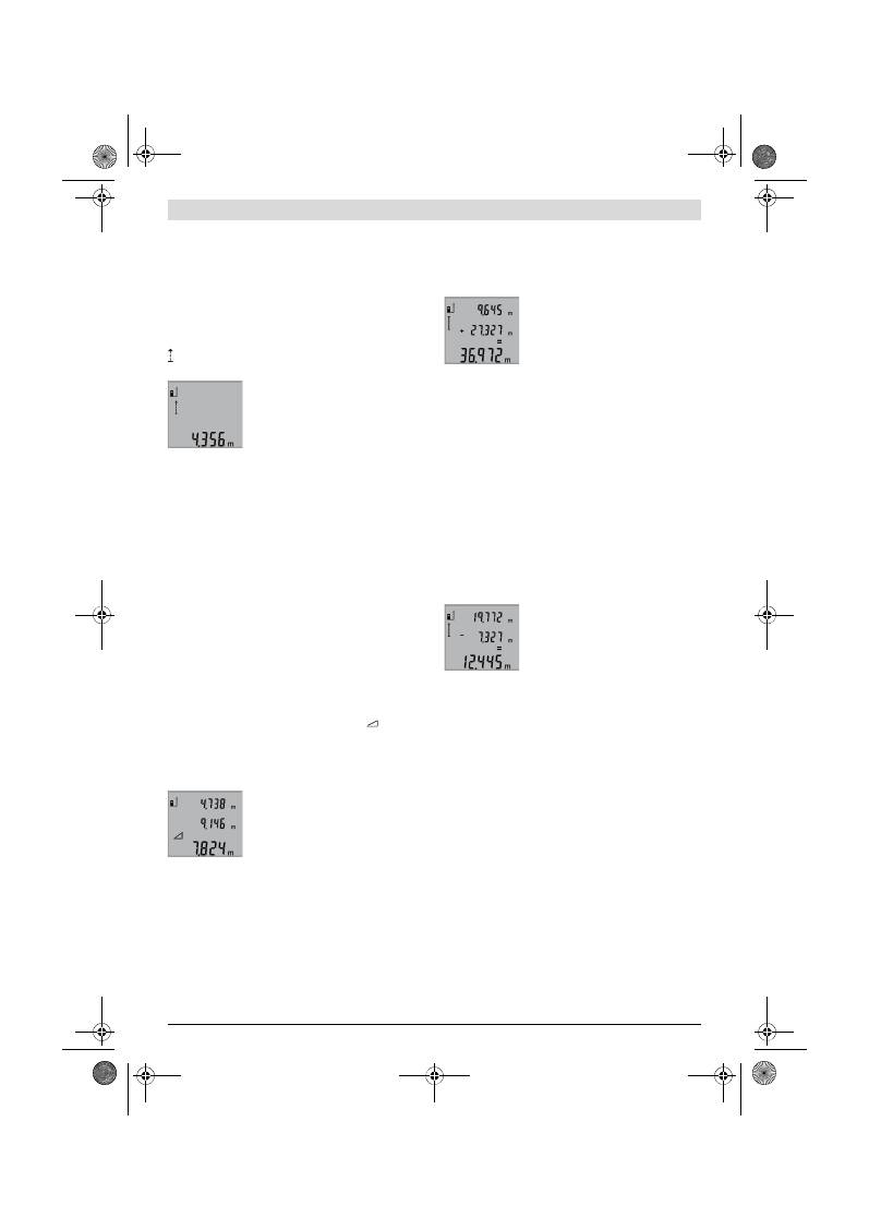
Ελληνικά |
73
Bosch Power Tools
2 609 140 773 | (4.12.12)
Διαρκής μέτρηση (βλέπε εικόνα E)
Κατά τη διαρκή μέτρηση το εργαλείο μέτρησης μπορεί να μετα-
τοπιστεί σχετικά ως προς το στόχο, οπότε και η τιμή μέτρησης
ενημερώνεται κάθε 0,5 s περίπου. Έτσι π.χ. μπορείτε να
απομακρυνθείτε από έναν τοίχο μέχρι την απόσταση που επιθυ-
μείτε διαβάζοντας παράλληλα στην οθόνη την τρέχουσα από-
σταση.
Για διαρκείς μετρήσεις πατήστε αλλεπάλληλα το πλήκτρο
9
μέ-
χρι την οθόνη να εμφανιστεί η ένδειξη για διαρκείς μετρήσεις
. Για να ξεκινήσετε τη μέτρηση πατήστε το πλήκτρο Μέτρηση
2
.
Η τρέχουσα τιμή μέτρησης εμφανίζεται στη
γραμμή αποτελεσμάτων
b
.
Η διαρκής μέτρηση τερματίζεται με πάτημα
του πλήκτρου Μέτρηση
2
. Η τελευταία τιμή
μέτρησης εμφανίζεται στη γραμμή αποτε-
λεσμάτων
b
. Η διαρκής μέτρηση ξαναρχίζει
όταν πατήσετε πάλι το πλήκτρο Μέτρηση
2
.
Η διαρκής μέτρηση απενεργοποιείται αυτόματα μετά από
5 min. Η τελευταία τιμή μέτρησης παραμένει στη γραμμή απο-
τελεσμάτων
b
.
Έμμεση μέτρηση υψών / Απλή μέτρηση κατά Πυθαγόρα
(βλέπε εικόνα F)
Η έμμεση μέτρηση υψών χρησιμεύει στην εξακρίβωση αποστά-
σεων οι οποίες δεν μπορούν να μετρηθούν άμεσα, ή επειδή κά-
ποιο εμπόδιο διακόπτει τη διαδρομή της ακτίνας ή επειδή δεν
διατίθεται πίνακας στόχευσης λέιζερ. Άριστα αποτελέσματα επι-
τυγχάνονται μόνο όταν τηρείται η ορθή γωνία που απαιτείται για
την εκάστοτε μέτρηση (Θεώρημα του Πυθαγόρα.
Προσέχετε, το σημείο αναφοράς της μέτρησης (π. χ. η πίσω ακ-
μή του εργαλείου μέτρησης) να παραμείνει ακριβώς στην ίδια
θέση κατά τη διάρκεια ολόκληρης της διαδικασίας μέτρησης.
Ανάμεσα στις διάφορες μεμονωμένες μετρήσεις η ακτίνα λέιζερ
παραμένει ενεργοποιημένη.
Πατήστε αλλεπάλληλα το πλήκτρο
3
μέχρι την οθόνη να εμφανι-
στεί η ένδειξη για την απλή πυθαγόρειο μέτρηση
.
Μετρήστε, όπως στη μέτρηση μηκών, πρώτα τη διαδρομή
«1»
και κατόπιν τη διαδρομή
«2»
. Δώστε προσοχή, η γωνία ανάμεσα
στη διαδρομή
«1»
και τη ζητούμενη διαδρομή
«X»
να είναι ορ-
θή.
Μετά το πέρας της τελευταίας μέτρησης το
αποτέλεσμα για τη ζητούμενη διαδρομή
«X»
εμφανίζεται στη γραμμή αποτελεσμά-
των
b
. Οι επί μέρους μετρήσεις βρίσκονται
στις γραμμές μέτρησης
a
.
Διαγραφή τιμών μέτρησης
Με σύντομο πάτημα του πλήκτρου
4
μπορείτε να σβήσετε σε
όλες τις λειτουργίες μέτρησης την εκάστοτε τελευταία εξακρι-
βωθείσα τιμή μέτρησης. Με αλλεπάλληλα σύντομα πατήματα
του πλήκτρου σβήνονται με ανάστροφη φορά όλες οι μεμονω-
μένες τιμές μέτρησης.
Πρόσθεση των τιμών μέτρησης
Για την άθροιση τιμών μέτρησης πρέπει πρώτα να διεξάγετε μια
οποιαδήποτε μέτρηση. Στη συνέχεια πατήστε το πλήκτρο άθροι-
σης
8
. Στην οθόνη εμφανίζεται η επιβεβαίωση
«+»
.
Για να αθροίσετε όγκους ή επιφάνειες πατήστε μετά την πρώτη
περαιωμένη διαδικασία μέτρησης το πλήκτρο άθροισης
8
. Στην
οθόνη εμφανίζεται, στα αριστερά του συμβόλου μέτρησης
όγκων/επιφανειών, η επιβεβαίωση
«+»
.
Διεξάγετε τώρα μια δεύτερη μέτρηση.
Για να καλέσετε το άθροισμα των δυο με-
τρήσεων πατήστε πάλι το πλήκτρο άθροι-
σης
8
. Ο υπολογισμός εμφανίζεται στις
γραμμές τιμών μέτρησης
a
και το άθροισμα
στη γραμμή αποτελεσμάτων
b
.
Μετά τον υπολογισμό του αθροίσματος μπορείτε στο αντίστοιχο
αποτέλεσμα να προσθέσετε και άλλες τιμές μέτρησης, όταν πριν
την εκάστοτε μέτρηση πατάτε το πλήκτρο άθροισης
8
.
Υποδείξεις σχετικά με την πρόσθεση:
– Δεν μπορείτε να αθροίσετε μεταξύ τους τις τιμές μέτρησης
μηκών, επιφανειών και όγκων. Π. χ., όταν σε μια τιμή μέτρη-
σης μήκους αθροίσετε την τιμή μέτρησης μιας επιφάνειας,
τότε, όταν πατήσετε το πλήκτρο άθροισης
8
, στην οθόνη εμ-
φανίζεται για λίγο η ένδειξη
«ERROR»
. Στη συνέχεια το ερ-
γαλείο μέτρησης μεταβαίνει στην λειτουργία που είχε ενερ-
γοποιηθεί τελευταία.
– Κάθε φορά προστίθεται το αποτέλεσμα μιας μέτρησης (π.χ.
μια τιμή όγκου), στις διαρκείς μετρήσεις η τιμή που δείχνεται
στη γραμμή αποτελεσμάτων
b
. Η πρόσθεση μεμονωμένων
τιμών μέτρησης από τις γραμμές τιμών μέτρησης
a
δεν είναι
εφικτή.
Αφαίρεση τιμών μέτρησης
Για να αφαιρέσετε τιμές μέτρησης πατήστε
το πλήκτρο αφαίρεσης
5
. Η ενέργεια αυτή
επιβεβαιώνεται στην οθόνη με εμφάνιση
του
«–»
. Συνεχίστε ανάλογα με την «Πρό-
σθεση των τιμών μέτρησης».
Υποδείξεις εργασίας
Γενικές υποδείξεις
Κατά τη διάρκεια της μέτρησης δεν επιτρέπεται να είναι καλυμ-
μένος ούτε ο φακός λήψης
12
ούτε η έξοδος της ακτίνας λέιζερ
11
.
Όταν μετράτε δεν επιτρέπεται να κινείτε το εργαλείο μέτρησης
(εξαιρείται η διαρκής μέτρηση). Γι’ αυτό πρέπει να ακουμπάτε
το εργαλείο μέτρησης κατά το δυνατό επάνω σε μια σταθερή
επιφάνεια.
Επιδράσεις στην περιοχή μέτρησης
Η περιοχή μέτρησης εξαρτάται από τις συνθήκες φωτισμού και
τις αντανακλαστικές ιδιότητες της επιφάνειας στόχευσης. Για να
μπορέσετε να διακρίνετε καλύτερα την ακτίνα λέιζερ όταν
εργάζεστε σε εξωτερικούς χώρους καθώς και υπό ισχυρή
ακτινοβολία να χρησιμοποιείτε τα γυαλιά παρατήρησης ακτίνας
λέιζερ
19
(ειδικό εξάρτημα) και τον πίνακα στόχευσης λέιζερ
20
(ειδικό εξάρτημα), ή να σκιάζετε την επιφάνεια στόχευσης.
Επιδράσεις στο αποτέλεσμα μέτρησης
Όταν μετράτε επί διαφορετικών επιφανειών δεν αποκλείεται,
διάφορα φυσικά φαινόμενα να οδηγήσουν σε εσφαλμένες με-
τρήσεις. Μεταξύ των άλλων πρόκειται για:
– διαφανείς επιφάνειες (π.χ. γυαλί, νερό),
– ανακλαστικές επιφάνειες (π.χ. στιλβωμένα μέταλλα, γυαλί),
OBJ_BUCH-1444-004.book Page 73 Tuesday, December 4, 2012 1:47 PM
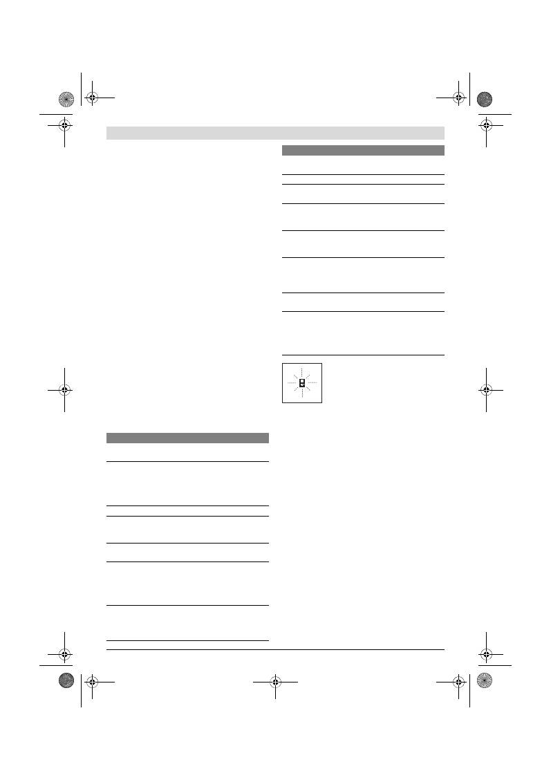
74
| Ελληνικά
2 609 140 773 | (4.12.12)
Bosch Power Tools
– πορώδεις επιφάνειες (π.χ. μονωτικά υλικά),
– τραχείς επιφάνειες (π.χ. σοβάδες, φυσικά πετρώματα).
Σ’ αυτές τις επιφάνειες χρησιμοποιήστε ενδεχομένως τον πίνα-
κα στόχευσης λέιζερ
20
(ειδικό εξάρτημα).
Εκτός αυτού δεν αποκλείονται σφάλματα μέτρησης όταν η επι-
φάνεια στόχευσης είναι κεκλιμένη.
Η τιμή μέτρησης μπορεί επίσης να επηρεαστεί και από στρώμα-
τα αέρα με διαφορετική θερμοκρασία ή/και από έμμεσες αντα-
νακλάσεις.
Έλεγχος ακρίβειας και της μέτρησης απόστασης
Μπορείτε να ελέγξτε την ακρίβεια ως εξής:
– Επιλέξτε μια διαρκώς αμετάβλητη και ακριβώς γνωστή δια-
δρομή μήκους 1 έως 10 m περίπου (π. χ. το πλάτος ενός χώ-
ρου ή το άνοιγμα μιας πόρτας). Η διαδρομή πρέπει να βρί-
σκεται σε ένα εσωτερικό χώρο και η επιφάνεια στόχευσης να
είναι λεία και με καλές ανακλαστικές ιδιότητες.
– Μετρήστε τη διαδρομή 10 φορές τη μια μετά την άλλη.
Η μέγιστη απόκλιση των μεμονωμένων μετρήσεων από τη μέση
τιμή επιτρέπεται να μην είναι μεγαλύτερη από ±2 mm. Να πρω-
τοκολλάτε τις μετρήσεις για να μπορείτε αργότερα να συγκρί-
νετε/να ελέγξετε την ακρίβεια.
Εργασία με το τρίποδο (ειδικό εξάρτημα)
Η χρήση ενός τριπόδου είναι απαραίτητη ιδιαίτερα σε μεγάλες
αποστάσεις. Τοποθετήστε το εργαλείο μέτρησης με το 1/4"
σπείρωμα
14
επάνω στην πλάκα ταχείας αντικατάστασης του
τριπόδου
18
ή επάνω σε ένα τρίποδο από το κοινό εμπόριο και
βιδώστε το καλά με τη βίδα στερέωσης της πλάκας ταχείας αντι-
κατάστασης.
Ρυθμίστε το επίπεδο αναφοράς για μέτρηση με τρίποδο με πά-
τημα το πλήκτρου
6
(επίπεδο αναφοράς Σπείρωμα).
Σφάλματα
–
Αιτίες και θεραπεία
Το εργαλείο μέτρησης επιτηρεί σε κάθε μέ-
τρηση την άψογη λειτουργία. Μόλις εξακρι-
βωθεί κάποιο σφάλμα, τότε στην οθόνη ανα-
βοσβήνει μόνο το διπλανό σύμβολο.
Σ’ αυτήν την περίπτωση, ή όταν τα παραπάνω
μέτρα θεραπείας δεν φέρουν αποτέλεσμα,
πρέπει να αποστείλετε το εργαλείο μέτρησης στο κέντρο
Service της Bosch μέσω του έμπορά σας.
Συντήρηση και Service
Συντήρηση και καθαρισμός
Να διαφυλάγετε και να μεταφέρετε το εργαλείο μέτρησης μόνο
μέσα στην προστατευτική τσάντα που το συνοδεύει.
Να διατηρείτε το εργαλείο μέτρησης πάντα καθαρό.
Μη βυθίσετε το εργαλείο μέτρησης σε νερό ή σε άλλα υγρά.
Καθαρίζετε τυχόν ρύπους και βρωμιές μ’ ένα υγρό, μαλακό πα-
νί. Μη χρησιμοποιείτε μέσα καθαρισμού ή διαλύτες.
Να περιποιείστε ιδιαίτερα το φακό λήψης
12
με την ίδια προσε-
κτικότητα που περιποιείστε τα γυαλιά σας και/ή τη φωτογραφική
σας μηχανή.
Αν, παρ’ όλες τις επιμελημένες μεθόδους κατασκευής και ελέγ-
χου, το εργαλείο μέτρησης σταματήσει κάποτε να λειτουργεί,
τότε η επισκευή του πρέπει να ανατεθεί σ’ ένα εξου-
σιοδοτημένο συνεργείο για ηλεκτρικά εργαλεία της Bosch. Μην
ανοίξετε ο ίδιος/η ίδια το εργαλείο μέτρησης.
Παρακαλούμε, όταν κάνετε διασαφητικές ερωτήσεις καθώς και
κατά την παραγγελία ανταλλακτικών, να αναφέρετε πάντοτε το
10ψήφιο αριθμό ευρετηρίου που βρίσκεται στην πινακίδα
κατασκευαστή του εργαλείου μέτρησης.
Αιτία
Θεραπεία
Η ένδειξη θερμοκρασίας (f) αναβοσβήνει, ανέφικτη μέ-
τρηση
Το εργαλείο μέτρησης βρίσκεται
εκτός της περιοχής της θερμο-
κρασίας λειτουργίας από – 10 °C
έως +50 °C (στη λειτουργία Διαρ-
κής μέτρηση έως +40 °C).
Περιμένετε μέχρι το ερ-
γαλείο μέτρησης να ανα-
κτήσει τη θερμοκρασία
λειτουργίας
Ένδειξη «ERROR» στην οθόνη
Πρόσθεση/Αφαίρεση τιμών με δια-
φορετικές μονάδες μέτρησης
Να προσθέτετε/να αφαι-
ρείτε μόνο ίδιες μονάδες
μέτρησης
Η γωνία μεταξύ ακτίνας λέιζερ και
στόχου είναι πολύ οξεία.
Αυξήστε τη γωνία μεταξύ
ακτίνας λέιζερ και στόχου
Η επιφάνεια στόχευσης αντανακλά
πολύ δυνατά (π.χ. καθρέφτης) ή
πολύ αδύνατα (π.χ. μαύρο υλικό), ή
πολύ ισχυρός φωτισμός περιβάλλο-
ντος.
Χρησιμοποιήστε τον πί-
νακα στόχευσης λέιζερ
20
(ειδικό εξάρτημα)
Έχει θαμπώσει η έξοδος ακτίνας λέ-
ιζερ
11
ή/και ο φακός λήψης
12
(π.χ. εξαιτίας πολύ γρήγορης αλ-
λαγής της θερμοκρασίας).
Στεγνώστε μ’ ένα μαλακό
πανί την έξοδο της ακτί-
νας λέιζερ
11
ή/και του
φακού λήψης
12
Η μετρηθείσα τιμή είναι μεγαλύτε-
ρη από 999999 m/m
2
/m
3
.
Διεξάγετε τη μέτρηση
σταδιακά
Το αποτέλεσμα της μέτρησης δεν είναι λογικό
Η επιφάνεια στόχευσης δεν αντ-
ανακλά σαφώς (π.χ. νερό, γυαλί).
Σκεπάστε την επιφάνεια
στόχευσης
Καλυμμένη έξοδος ακτίνας λέιζερ
11
ή καλυμμένος φακός λήψης
12
.
Διατηρείτε ελεύθερη τη
έξοδο ακτίνας λέιζερ
11
ή/και το φακό λήψης
12
Ρυθμίσατε λάθος επίπεδο αναφο-
ράς
Επιλέξτε το αντίστοιχο
κατάλληλο επίπεδο ανα-
φοράς
Εμπόδιο στη διαδρομή της ακτίνας
λέιζερ
Το σημείο λέιζερ πρέπει
να βρίσκεται ολόκληρο
επάνω στην επιφάνεια
στόχευσης.
Η ένδειξη παραμένει αμετάβλητη ή το εργαλείο αντιδρά
απροσδόκητα κατά το πάτημα πλήκτρου
Σφάλμα λογισμικού
Αφαιρέστε τις μπαταρίες,
επανατοποθετήστε τις
και ακολούθως ενεργο-
ποιήστε πάλι το εργαλείο
μέτρησης.
Αιτία
Θεραπεία
OBJ_BUCH-1444-004.book Page 74 Tuesday, December 4, 2012 1:47 PM
Türkçe |
75
Bosch Power Tools
2 609 140 773 | (4.12.12)
Το εργαλείο μέτρησης πρέπει να αποστέλλεται για επισκευή μέ-
σα στην προστατευτική τσάντα
17
.
Service και παροχή συμβουλών χρήσης
Το Service απαντά στις ερωτήσεις σας σχετικά με την επισκευή
και τη συντήρηση του προϊόνος σας καθώς για τα κατάλληλα
ανταλλακτικά:
www.bosch-pt.com
Η ομάδα παροχής συμβουλών της Bosch απαντά ευχαρίστως
στις ερωτήσεις σας σχετικά με τα προϊόντα μας και τα ανταλλα-
κτικά τους.
Ελλάδα
Robert Bosch A.E.
Ερχείας 37
19400 Κορωπί – Αθήνα
Tel.: 210 5701270
Fax: 210 5701283
www.bosch.com
www.bosch-pt.gr
ABZ Service A.E.
Tel.: 210 5701380
Fax: 210 5701607
Απόσυρση
Τα εργαλεία μέτρησης, τα εξαρτήματα και οι συσκευασίες πρέ-
πει να ανακυκλώνονται με τρόπο φιλικό προς το περιβάλλον.
Μην ρίξετε τα εργαλεία μέτρησης και τις μπαταρίες στα απορ-
ρίμματα του σπιτιού σας!
Μόνο για χώρες της ΕΕ:
Σύμφωνα με την Κοινοτική Οδηγία
2002/96/EΚ τα άχρηστα εργαλεία μέτρη-
σης, και σύμφωνα με την Κοινοτική Οδηγία
2006/66/EΚ οι χαλασμένες ή αναλωμένες
μπαταρίες δεν είναι πλέον υποχρεωτικό να
συλλέγονται ξεχωριστά για να ανακυκλωθούν
με τρόπο φιλικό προς το περιβάλλον.
Τηρούμε το δικαίωμα αλλαγών.
Türkçe
Güvenlik Talimatı
Ölçme cihazı ile tehlikesiz ve güvenli bi-
çimde çalışabilmek için bütün güvenlik ta-
limatı okunmalı ve uyarılara uyulmalıdır.
Ölçme cihazı üzerindeki uyarı etiketlerini
hiçbir zaman görünmez hale getirmeyin.
BU GÜVENLİK TALİMATINI GÜVENLİ BİR
YERDE SAKLAYIN.
Dikkat – Burada belirtilen kullanım veya ayar hükümle-
rine uyulmadığı veya başka yöntemler kullanıldığı tak-
dirde cihazın çıkaracağı ışınlar kullanıcı için tehlikeli
olabilir.
Bu ölçme cihazı İngilizce uyarı etiketi ile teslim edilir
(grafik sayfasındaki ölçme cihazı şeklinde 15 numara
ile işaretlennmiştir).
İlk kullanımdan önce İngilizce uyarı etiketinin üzerine
cihazla birlikte teslim edilen kendi dilinizdeki uyarı eti-
ketini yapıştırın.
Lazer ışınını başkalarına veya hayvanlara doğrultmayın
ve kendiniz de lazer ışınına bakmayın.
Bu ölçme cihazı
IEC 60825-1 uyarınca 2. Sınıf lazer ışını üretir. Bu nedenle
başkalarının gözünü kamaştırabilirsiniz.
Lazer gözlüğünü güneş gözlüğü olarak kullanmayın.
La-
zer gözlüğü insan gözünü lazer ışınından korumaz, ancak
lazer ışınının daha iyi görülmesini sağlar.
Lazer gözlüğünü güneş gözlüğü olarak veya trafikte
kullanmayın.
Lazer gözlüğü mor ötesi ışınlarına (UV) karşı
tam olarak koruma sağlamaz ve renk algılamasını azaltır.
Ölçme cihazını sadece kalifiye uzmanlara ve orijinal ye-
dek parça kullanma koşulu ile onartın.
Bu yolla ölçme ci-
hazının güvenliğini her zaman sağlarsınız.
Çocukların denetiminiz dışında lazerli ölçme cihazını
kullanmasına izin vermeyin.
Çocuklar istemeden başka-
larının gözünü kamaştırabilir.
Bu ölçme cihazı ile yakınında yanıcı sıvılar, gazlar veya
tozların bulunduğu patlama tehlikesi olan yerlerde ça-
lışmayın.
Ölçme cihazı içinde toz veya buharları tutuştura-
bilecek kıvılcımlar üretilebilir.
Ürün ve işlev tanımı
Lütfen ölçme cihazının bulunduğu kapağı açın ve kullanım kıla-
vuzunu okuduğunuz sürece bu kapağı açık tutun.
Usulüne uygun kullanım
Bu ölçme cihazı; uzaklıkların, uzunlukların, yüksekliklerin, ara-
lıkların ölçülmesi ile yüzey ve hacimlerin hesaplanması için ta-
sarlanmıştır. Bu ölçme cihazı hem kapalı mekanlarda hem de
açık havada ölçüm yapmaya uygundur.
OBJ_BUCH-1444-004.book Page 75 Tuesday, December 4, 2012 1:47 PM

76
| Türkçe
2 609 140 773 | (4.12.12)
Bosch Power Tools
Teknik veriler
Şekli gösterilen elemanlar
Şekli gösterilen cihaz elemanlarının numaraları ölçme cihazı-
nın şeklinin bulunduğu grafik sayfasında bulunmaktadır.
1
Display
2
Ölçme tuşu
3
Yüzey, hacim ve endirekt yükseklik ölçümü (Pisagor) tu-
şu
4
Silme tuşu / Açma/kapama tuşu **
5
Eksi tuşu
6
Referans düzlem seçme tuşu
7
Taşıma halkası yuvası
8
İmpuls tuşu
9
Uzunluk ve sürekli ölçüm tuşu
10
Batarya gözü kapağı
11
Lazer ışını çıkma yeri
12
Algılama merceği
13
Seri numarası
14
1/4"-Diş
15
Lazer uyarı etiketi
16
Batarya gözü kapak kilidi
17
Koruyucu çanta
18
Sehpa*
19
Lazer gözlüğü*
20
Lazer hedef tablası*
* Şekli gösterilen veya tanımlanan aksesuar standart teslimat kap-
samında değildir.
** Genişletilmiş fonksiyonları çağırmak için tuşu basılı tutun.
Gösterge elemanları
a
Ölçme değeri satırları
b
Sonuç satırı
Dijital lazerli uzaklıkölçer
GLM 50
Professional
Ürün kodu
3 601 K72 2..
Ölçme alanı
0,05 –50 m
A)
Ölçme hassaslığı (tipik)
±1,5 mm
B)
En küçük gösterge birimi
1 mm
İşletme sıcaklığı
–10 °C...+50 °C
C)
Saklama sıcaklığı
–20 °C...+70 °C
Maksimum nispi hava nemi
90 %
Lazer sınıfı
2
Lazer tipi
635 nm, <1 mW
Lazer ışını çapı (25 °C’de) yak.
– 10 m uzaklıkta
– 50 m uzaklıkta
6 mm
35 mm
Kesme otomatiği süresi, yak.
– Lazer
– Ölçme cihazı (Ölçüm olmadan)
20 s
5 dak
Bataryalar
Akü hücreleri
2 x 1,5 V LR03 (AAA)
2 x 1,2 V HR03 (AAA)
Batarya kullanım ömrü, yak.
– Tekil ölçümler
– Sürekli ölçüm
10000
D)
2,5 h
D)
Ağırlığı EPTA-Procedure 01/2003’e göre
0,14 kg
Ölçüleri
53 x 114 x 30 mm
Koruma türü
IP 54 (Toza ve püsküren suya karşı korunmalı)
A) Lazer ışını yüzeyden ne kadar iyi geri yansıtılırsa (aynanın yansıtması gibi değil dağılıcı olarak) ve lazer noktası ortam aydınlığına göre ne kadar aydın-
lıksa (örneğin iç mekanlarda veya alaca karanlıklarda) lazer ışınının erişim uzaklığı da o kadar büyük olur). Elverişsiz koşullarda (örneğin açık havada
şiddetli güneş ışığı altında yapılan ölçmelerde) hedef tablasının kullanılması gerekli olabilir.
B) Ölçme cihazının arka kenarından itibaren yapılan ölçme işlemlerinde. Şiddetli güneş ışını veya iyi yansıtma yapmayan yüzeyler gibi elverişsiz koşul-
larda maksimim sapma
±
10 mm’dir
–
50 m’lik mesafede. Elverişli koşullarda
±
0,05 mm/m’lik bir etki hesaba katılmalıdır.
C) Sürekli ölçüm fonksiyonunda maksimum işletme sıcaklığı + 40
°C
’dir.
D) 1,2 Volt akü hücreleri ile 1,5 Volt bataryalara oranla daha az ölçme işlemi yapılabilir. Belirtilen işletim süresi Display aydınlatması olmadan yürütülen
işletime ilişkindir.
Ölçme cihazınızın tam olarak belirlenmesi tip etiketi üzerindeki seri numarası
13
ile olur.
OBJ_BUCH-1444-004.book Page 76 Tuesday, December 4, 2012 1:47 PM
Türkçe |
77
Bosch Power Tools
2 609 140 773 | (4.12.12)
c
Ölçme fonksiyonları
d
Lazer açık
e
Ölçme için referans düzlem
f
Sıcaklık uyarısı
g
Batarya uyarısı
h
Hata göstergesi
“ERROR”
Montaj
Bataryaların takılması/değiştirilmesi
Bu ölçme cihazının alkali mangan bataryalarla kullanılması
tavsiye edilir.
1,2 V akülerle 1,5 V bataryalara oranla daha az ölçüm yapıla-
bilir.
Batarya gözü kapağını
10
açmak için kilide
16
basın ve batar-
ya gözü kapağını alın. Bataryaları veya aküleri yerleştirin. Ba-
tarya gözü kapağının iç tarafındaki şekle bakarak doğru kutup-
lama yapmaya dikkat edin.
Bataryaları veya aküleri yerleştirirken batarya gözündeki şek-
le bakarak doğru kutuplama yapın.
Batarya sembolü
Display’de ilk kez göründüğünde daha en
azından 100 ölçme işlemi yapılabilir. Sürekli ölçüm fonksiyo-
nu pasif haldedir.
Batarya sembolü
yanıp söndüğünde bataryaları veya akü
hücrelerini değiştirmelisiniz. Artık ölçme yapmak mümkün
değildir.
Bütün bataryaları veya aküleri aynı anda değiştirin. Daima ay-
nı üreticinin aynı kapasitedeki bataryalarını veya akülerini kul-
lanın.
Ölçme cihazını uzun süre kullanmayacaksanız batarya-
ları veya aküleri çıkarın.
Uzun süre kullanım dışı kaldıkla-
rında bataryalar veya aküler korozyona uğrar ve kendilikle-
rinden boşalırlar.
İşletme
Çalıştırma
Açık durumdaki ölçme cihazını bırakıp gitmeyin ve işi-
niz bitince cihazı kapatın.
Lazer ışını başkalarının gözünü
alabilir.
Ölçme cihazınızı nemden/ıslaklıktan ve doğrudan gü-
neş ışınından koruyun.
Ölçme cihazını aşırı sıcaklıklara ve büyük sıcaklık
değişikliklerine maruz bırakmayın.
Örneğin cihazı uzun
süre otomobil içinde bırakmayın. Büyük sıcaklık değişiklik-
lerinde ölçme cihazını çalıştırmadan önce bir süre sıcaklık
dengelenmesini bekleyin. Aşırı sıcaklıklarda veya büyük sı-
caklık değişikliklerinde ölçme cihazının hassaslığı kaybola-
bilir.
Ölçme cihazını şiddetli çarpma ve düşmelerden koru-
yun.
Ölçme cihazı dışarıdan şiddetli bir etkiye maruz kaldı-
ğında çalışmaya devam etmeden önce bir hassaslık kontro-
lü yapmalısınız (Bakınız: “Uzaklık ölçümü hassaslık kontro-
lü”, sayfa 79).
Açma/kapama
Ölçme cihazını açmak için aşağıdaki seçeneklere sahipsiniz:
– Açma/kapama tuşuna
4
basın: Ölçme cihazı açılır ve uzun-
luk ölçme fonksiyonunda bulunur. Lazer açılmaz.
– Ölçme tuşuna
2
basın: Ölçme cihazı ve lazer açılır. Ölçme
cihazı uzunluk ölçme fonksiyonunda bulunur.
Lazer ışınını kişilere ve hayvanlara doğrultmayın ve
uzak mesafeden de olsa lazer ışınına bakmayın.
Ölçme cihazını
kapatmak
için açma/kapama tuşuna
4
uzun
süre basın.
Yaklaşık 5 dakika boyunca ölçme cihazında hiçbir tuşa basıl-
mazsa ölçme cihazı bataryaları korumak üzere otomatik ola-
rak kapanır.
Ölçme işlemi
Ölçme tuşuna
2
basılarak açıldığında ölçme cihazı uzunluk öl-
çüme fonksiyonunda bulunur. Diğer ölçme fonksiyonlarını ilgi-
li fonksiyon tuşuna basarak ayarlayabilirsiniz (Bakınız: “Ölçme
fonksiyonları”, sayfa 78).
Cihaz açıldıktan sonra ölçüm için referans düzlemi olarak ci-
hazın arka kenarı seçilmiştir. Referans düzlemi tuşuna
6
basa-
rak referans düzlemini değiştirebilirsiniz (Bakınız: “Referans
düzlemlerin seçilmesi”, sayfa 77).
Ölçme cihazını seçilen referans düzlemi ile istediğiniz ölçme
start noktasına (örneğin duvara) yerleştirin.
Lazer ışınını açmak için ölçme tuşuna
2
kısa süre basın.
Lazer ışınını kişilere ve hayvanlara doğrultmayın ve
uzak mesafeden de olsa lazer ışınına bakmayın.
Lazer ışınını hedef yüzeye doğrultun. Ölçme işlemini başlat-
mak için ölçme tuşuna
2
yeniden kısa süre basın.
Sürekli ölçüm fonksiyonunda ölçme işlemine cihaz açıldıktan
hemen sonra başlanır.
Ölçme değeri tipik olarak 0,5 saniye içinde ve en geç 4 saniye
sonra gösterilir. Ölçme işleminin süresi uzaklığa, ışık koşulla-
rına ve hedef yüzeyin yansıtma özelliklerine bağlıdır. Ölçme iş-
lemi sona erdiğinde lazer ışını otomatik olarak kapanır.
Nişan almadan kesme lazeri yaklaşık 20 saniye içinde ölçme
yapmazsa, lazer ışını bataryaları korumak üzere otomatik ola-
rak kapanır.
Referans düzlemlerin seçilmesi (Bakınız: Şekil A)
Ölçme işlemi için üç farklı referans düzleminden birini seçebi-
lirsiniz:
– Ölçme cihazının arka kenarı (örneğin duvara dayamada),
– ölçme cihazının ön kenarı (örneğin bir masa kenarından iti-
baren ölçme işleminde),
– dişin
14
ortası (örneğin sehpa ile ölçme işlemleri için).
Referans düzlemi seçmek için tuşa
6
Display’de istediğiniz re-
ferans düzlemi görününceye kadar basın. Ölçme cihazının her
Uzunluk ölçme
Sürekli ölçüm
Yüzey ölçme
Hacim ölçme
Tekli Pisagor ölçümü
OBJ_BUCH-1444-004.book Page 77 Tuesday, December 4, 2012 1:47 PM
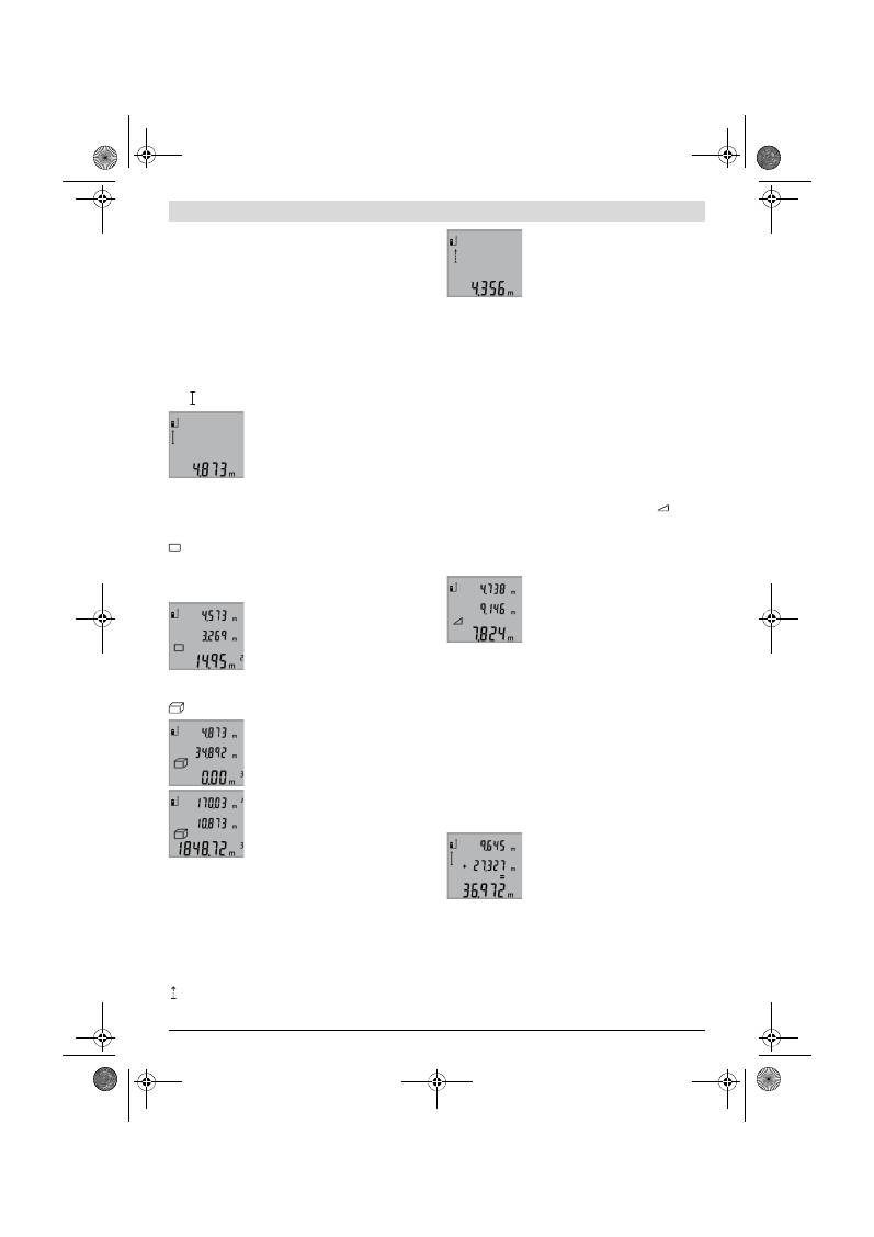
78
| Türkçe
2 609 140 773 | (4.12.12)
Bosch Power Tools
açılışında referans düzlem olarak ölçme cihazının arka kenarı
ayarlanır.
Display aydınlatması
Display aydınlatması ortam aydınlığına göre otomatik olarak
aktifleşir. Display aydınlatması açıldıktan sonra hiçbir tuşa ba-
sılmazsa, bataryaları korumak üzere bu aydınlatma işlevi sö-
nümlendirilir.
Ölçme fonksiyonları
Basit uzunluk ölçümü (Bakınız: Şekil B)
Uzunluk ölçümü için tuşa
9
Display’de uzunluk ölçme göster-
gesi görününceye kadar basın.
Lazeri açmak ve ölçme yapmak için her
defasında kısa süre ile ölçme tuşuna
2
ba-
sın.
Ölçme değeri sonuç satırında
b
gösterilir.
Arka arkaya çok sayıda uzunluk ölçümü
yapılınca son ölçümlerin sonuçları ölçme değeri satırlarında
a
gösterilir.
Alan (yüzey) ölçümü (Bakınız: Şekil C)
Yüzey ölçümü için tuşa
3
Display’de yüzey ölçme göstergesi
görününceye kadar basın.
Daha sonra aynen uzunluk ölçümünde olduğu gibi uzunluğu ve
genişliği arka arkaya ölçün. Her iki ölçme işlemi sırasında lazer
ışını açık kalır.
İkinci ölçüm tamamlandıktan sonra yüzey
(alan) otomatik olarak hesaplanır ve so-
nuç satırında
b
gösterilir. Tekil ölçme de-
ğerleri ölçme değeri satırlarında
a
bulu-
nur.
Hacim ölçümü (Bakınız: Şekil D)
Hacim ölçümü için tuşa
3
Display’de hacim ölçme göstergesi
görününceye kadar basın.
Daha sonra aynen uzunluk ölçümünde ol-
duğu gibi uzunluğu, genişliği ve yüksekliği
arka arkaya ölçün. Her üç ölçme işlemi sı-
rasında da lazer ışını açık kalır.
Üçüncü ölçüm bittikten sonra hacim oto-
matik olarak hesaplanır ve sonuç satırın-
da
b
gösterilir. Münferit ölçüm değerleri
ölçüm değeri satırında
a
bulunur.
999999 m
3
üzerindeki değerler gösteri-
lemez ve Display’de
“ERROR”
gözükür.
Ölçülecek hacmi bölümlere ayarın ve sonra tek tek değerleri
hesaplayarak bir araya getirin.
Sürekli ölçüm (Bakınız: Şekil E)
Sürekli ölçümde ölçme cihazı hedefe göre hareket ettirilebilir
ve ölçme değeri yaklaşık her 0,5 saniyede güncellenir. Örne-
ğin bir duvardan istediğiniz bir mesafeye kadar uzaklaşabilir-
siniz, güncel uzaklık daima okunabilir.
Sürekli ölçüm için tuşa
9
Display’de sürekli ölçme göstergesi
görününceye kadar basın. Sürekli ölçümü başlatmak için
ölçme tuşuna
2
basın.
Güncel değer sonuç satırında
b
gösterilir.
Ölçme tuşuna
2
basılınca sürekli ölçüm
fonksiyonu sonlandırılır. Son ölçme değe-
ri sonuç satırında
b
gösterilir. Ölçme tuşu-
na
2
yeniden basıldığında sürekli ölçüm
fonksiyonu tekrar başlatılır.
Sürekli ölçüm 5 dakika sonra otomatik olarak kapanır. Son
ölçme değeri sonuç satırında
b
gösterilir.
Endirekt yükseklik ölçümü / Tekli Pisagor ölçümü
(Bakınız: Şekil F)
Endirekt yükseklik ölçümü, ışın yolunda bir engel bulunduğun-
dan veya yansıma yapan bir hedef yüzey olmadığından doğru-
dan ölçülemeyen uzaklıkların ölçülmesine yarar. Kusursuz so-
nuçlar ancak ilgili ölçme işleminde gerekli dik açıya tam olarak
uyulduğunda sağlanır (Pisagor teoremi).
Tekli ölçmeler esnasında ölçme işlemine ait refarans noktası-
nın (örneğin ölçme cihazının arka kenarı) tam olarak aynı yer-
de kalmasına dikkat edin.
Tekil ölçümler arasında lazer ışını açık kalır.
Tuşa
3
Display’de tekil Pisagor ölçümü göstergesi
görü-
nünceye kadar basın.
Uzunluk ölçümünde olduğu gibi
“1”
ve
“2”
uzunluklarını bu sı-
ra ile ölçün.
“1”
uzunluğu ile aranan
“X”
uzunluğu arasında dik
açı olmasına dikkat edin.
Son ölçme işlemi tamamlandıktan sonra
aranan
“X”
uzunluğu sonuç satırında
b
gösterilir. Tekil ölçüm değerleri ölçme de-
ğeri satırlarında
a
bulunur.
Ölçme değerlerinin silinmesi
Tuşa
4
kısa süre basarak bütün ölçme fonksiyonlarında son
olarak belirlenen tekil ölçme değerini silebilirsiniz. Tuşa çok
defa kısa süreli basarsanız tekil ölçme değerleri ters sıra ile si-
linir.
Ölçme değerlerinin toplanması
Ölçme değerlerini toplamak için önce istediğiniz bir ölçme iş-
lemini gerçekleştirin. Daha sonra artı tuşuna
8
basın. Disp-
lay’de onay için
“+”
görünür.
Hacimleri veya yüzeyleri toplamak için tamamlanan ilk ölçme
işlminden sonra artı tuşuna
8
basın. Display’de onay için ha-
cim/yüzey sembolünün solunda
“+”
görünür.
Daha sonra ikinci ölçme işlemini gerçekleştirin.
Her iki ölçme işleminin toplamını sormak
için artı tuşuna
8
bir kez daha basın. He-
saplama ölçme değeri satırlarında
a
gös-
terilir, sonuç sonuç satırında
b
görünür.
Toplam değer hesapladıktan sonra, ölç-
me işleminden önce artı tuşuna
8
basıla-
rak bu toplama daha başka ölçme sonuçları da eklenebilir.
Toplamaya ilişkin açıklamalar:
– Uzunluk, yüzey ve hacim ölçüm değerleri karışık olarak top-
lanamaz. Örneğin bir uzunluk ölçme değeri ile yüzey ölçme
değeri toplanacak olursa, artı tuşuna
8
basındığında Disp-
lay’de kısa süre
“ERROR”
gözükür. Daha sonra ölçme ciha-
zı son olarak aktif olan ölçme fonksiyonuna geçer.
OBJ_BUCH-1444-004.book Page 78 Tuesday, December 4, 2012 1:47 PM
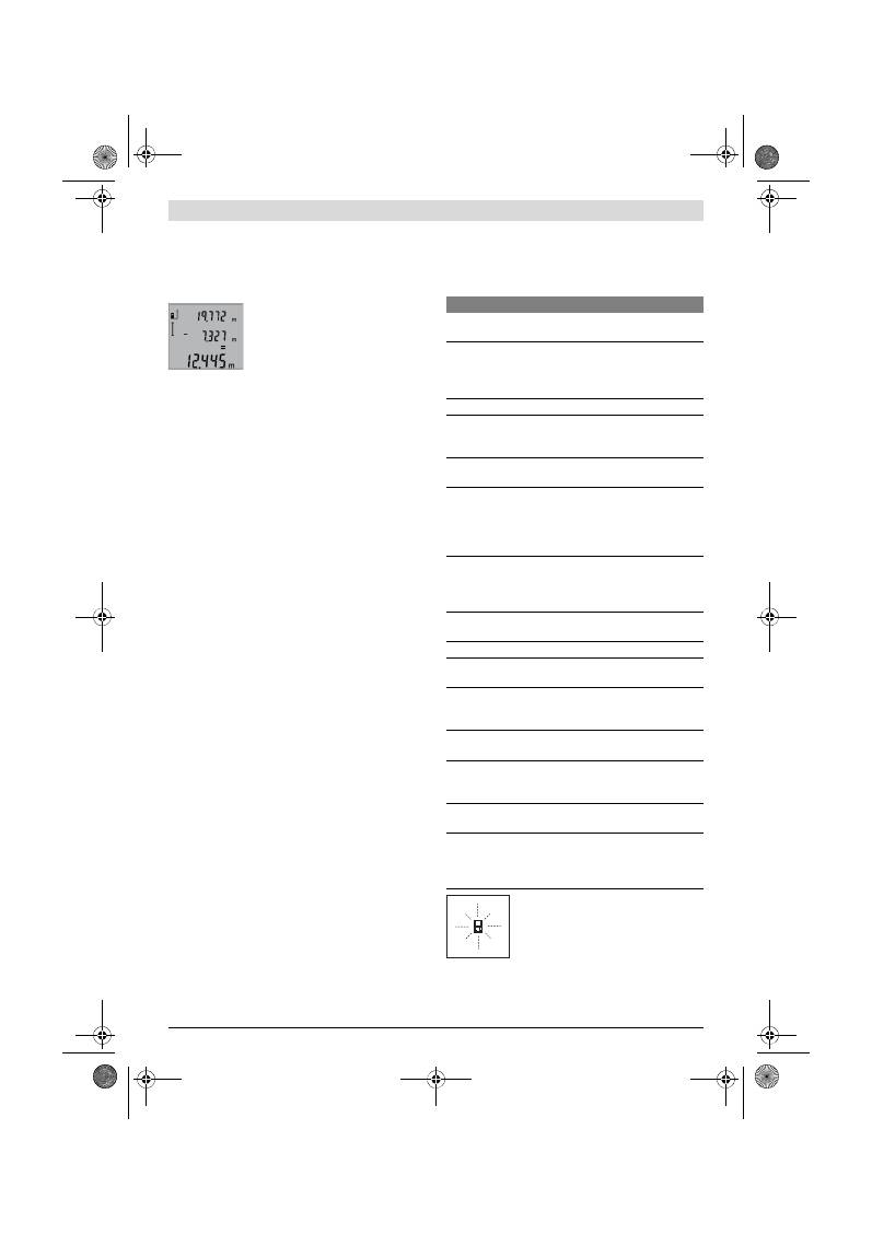
Türkçe |
79
Bosch Power Tools
2 609 140 773 | (4.12.12)
– Her defasında bir ölçümün sonucu toplanır (örneğin hacim
değeri), sürekli ölçümde ise sonuç satırında
b
gösterilen
ölçme değeri toplanır. Ölçme değeri satırlarında
a
gösteri-
len tekil ölçme değerlerinin toplanması mümkün değildir.
Ölçme değerlerinin çıkarılması
Ölçme değerlerini çıkarmak için eksi tuşu-
na
5
basın, Display’de onay için
“–”
gözü-
kür. Diğer adımlar “Ölçme değerlerinin
toplanması” bölümünde olduğu gibidir.
Çalışırken dikkat edilecek hususlar
Genel açıklamalar
Algılama merceği
12
ve lazer ışını çıkışı
11
ölçme işlemi sıra-
sında kapatılmamalıdır.
Ölçme cihazı bir ölçme işlemi esnasında hareket ettirilemez
(sürekli ölçüm fonksiyonu hariç). Bu nedenle ölçme cihazını
sabit bir dayamağa veya yüzeye yerleştirin.
Ölçme alanı (aralığı) üzerindeki etkiler
Ölçme alanı (aralığı) ışık koşullarına ve hedef yüzeyin yansıt-
ma özelliklerine bağlıdır. Açık havada ve şiddetli güneş ışığı al-
tında çalışırken lazer ışınının daha iyi görünmesi için lazer göz-
lüğü
19
(aksesuar), lazer hedef tablası
20
(aksesuar) kullanın
veya hedef yüzeyini güneş ışınından koruyun.
Ölçme sonucuna etkiler
Fiziksel etkiler nedeniyle, çeşitli yüzeylerde ölçme yapılırken
hatalı sonuçların ortaya çıkması mümkündür. Bunlar şunlar-
dır:
– Saydam yüzeyler (örneğin cam, su),
– Parlayan yüzeyler (örneğin polisajlı metal, cam),
– Gözenekli yüzeyler (örneğin yalıtım malzemeleri),
– Yüzey yapısı (örneğin ham sıva, doğal taş).
Bu gibi yüzeylerde ölçme yaparken gerekiyorsa lazer hedef
tablası
20
(aksesuar) kullanın.
Ayrıca hedef yüzeye eğik olarak nişan alınırsa hatalı ölçme so-
nuçları ortaya çıkabilir.
Yine aynı şekilde farklı sıcaklıklara sahip hava katmanları ve
endirekt olarak alınan yansımalar hatalı ölçme sonuçlarına ne-
den olabilir.
Uzaklık ölçümü hassaslık kontrolü
Uzaklık ölçümü hassaslığını şu şekilde kontrol edebilirsiniz:
– 1 ile 10 metre arasında uzunluğunu tam olarak bildiğiniz ve
hiç değişmeyen bir ölçme hattı seçin (örneğin bir oda ge-
nişliği, kapı aralığı). Ölçme hattı iç mekanda olmalı, ölçme
işleminin hedef yüzeyi parlak ve iyi yansıtıcı olmalıdır.
– Bu mesafeyi 10 kez arka arkaya ölçün.
Tekil ölçümlerin ortalama değerden sapması maksimum
±2 mm olmalıdır. Daha sonra hassaslığı karşılaştırabilmek
için ölçme sonuçlarını bir tutanağa geçirin.
Sehpa ile çalışmak (aksesuar)
Sehpanın kullanılması özellikle uzak mesafelerde gereklidir.
Ölçme cihazının 1/4"lik dişini
14
sehpanın
18
hızlı değiştirilir
levhasına veya piyasada bulunan bir fotoğraf makinesi seh-
pasına yerleştirin. Cihazı hızlı değiştirilir levhanın tespit vidası
ile sıkın.
Sehpa ile ölçme yapmak için referans düzlemini referans düz-
lemi tuşuna
6
basmak suretiyle uygun biçimde ayarlayın (Re-
ferans düzlemi dişi).
Hataların nedenleri ve giderilmeleri
Bu ölçme cihazı her ölçme işlemininin fonk-
siyonunn kusursuz olup olmadığını kontrol
eder. Bir hata tespit edilirse, Display’de sa-
dece yandaki sembol yanıp söner. Bu gibi
durumlarda veya yukarıda anılan hata gider-
me yöntemleri ile ilgili hatalar giderilemiyor-
sa, cihazınızı yetkili satıcınız yardımı ile Bosch Müşteri Hizme-
tine gönderin.
Nedeni
Giderilmesi
Sıcaklık uyarısı (f) yanıp sönüyor, ölçme işlemi mümkün
değil
Ölçme cihazı – 10 °C ila
+ 50 °C’lik işletme sıcaklığı aralığı-
nın dışında (Sürekli ölçüm
fonksiyonunda +40 °C’ye kadar).
Ölçme cihazı normal iş-
letim sıcaklığına kavu-
şuncaya kadar bekleyin
Display’de “ERROR” göstergesi
Ölçme değerlerinin farklı ölçme bi-
rimleri ile toplanması ve çıkarılma-
sı
Sadece aynı ölçme bi-
rimli ölçme değerlerini
toplayın ve çıkarın
Lazer ışını ile hedef arasındaki açı
çok dar.
Lazer ışını ile hedef ara-
sındaki açıyı büyütün
Hedef yüzey çok fazla yansıtma ya-
pıyor (örneğin ayna) veya çok az
yansıtma yapıyor (örneğin siyah
renkli madde) veya çevre ışığı çok
şiddetli.
Lazer hedef tablası
20
(aksesuar) kullanın
Lazer ışını çıkışı
11
buğulu veya al-
gılama merceği
12
buğulu (örneğin
aşırı sıcaklık değişiklikleri nedeni
ile).
Yumuşak bir bez veya
havlu ile lazer ışını çıkı-
şını
11
veya algılama
merceğini
12
kurulayın
Hesaplanan değer
999999 m/m
2
/m
3
’ten büyük.
Hesaplamayı ara kade-
melere ayırın
Ölçme sonucu makul değil
Hedef yüzey açık biçimde yansıt-
ma yapıyor (örneğin su, cam).
Hedef yüzeyi kapatın
Lazer ışını çıkışı
11
veya algılama
merceği
12
kapalı.
Lazer ışını çıkışını
11
ve
algılama merceğini
12
açık tutun
Yanlış referans düzlem ayarlanmış Referans düzlemi ölçü-
me uygun olarak seçin
Lazer ışınının önünde engel var
Lazer noktası hedef yü-
zeyde tam olarak bulun-
malıdır.
Gösterge hiç değişmeden kalıyor veya ölçme cihazı tuşa
basılınca beklenmedik reaksiyon gösteriyor
Yazılımda hata
Bataryaları çıkarın ve
tekrar taktıktan sonra
ölçme cihazını yeniden
açın.
OBJ_BUCH-1444-004.book Page 79 Tuesday, December 4, 2012 1:47 PM

80
| Türkçe
2 609 140 773 | (4.12.12)
Bosch Power Tools
Bakım ve servis
Bakım ve temizlik
Ölçme cihazını daima birlikte teslim edilen koruyucu çanta
içinde saklayın ve taşıyın.
Ölçme cihazını daima temiz tutun.
Ölçme cihazını hiçbir zaman suya veya başka sıvılara daldır-
mayın.
Kirleri ve pislikleri nemli, temiz bir bezle silin. Deterjan veya
çözücü madde kullanmayın.
Özellikle algılama merceğinin
12
bakımını dikkatli biçimde,
gözlükle veya bir fotoğraf makinesinin merceği için kullanıla-
cak bir araçla yapın.
Dikkatli üretim ve test yöntemlerine rağmen ölçme cihazı arıza
yapacak olursa, onarım Bosch Elektrikli El Aletleri için yetkili
bir serviste yaptırılmalıdır. Ölçme cihazını kendiniz açmayın.
Bütün sorularınız ve yedek parça siparişlerinizde mutlaka ci-
hazınızın tip etiketindeki 10 haneli ürün kodunu belirtin.
Onarılması gerektiğinde ölçme cihazını koruyucu çanta
17
içinde yollayın.
Müşteri hizmeti ve uygulama danışmanlığı
Müşteri hizmeti ürününüzün onarım, bakım ve yedek parçala-
rına ilişkin sorularınızı yanıtlandırır. Demonte görünüşler ve
yedek parçalara ilişkin ayrıntılı bilgiyi aşağıdaki Web sayfasın-
da bulabilirsiniz:
www.bosch-pt.com
Bosch uygulama danışmanlığı ekibi ürünlerimize ve ilgili akse-
suara ilişkin sorularınızda size memnuniyetle yardımcı olur.
Türkçe
Bosch San. ve Tic. A.S.
Ahi Evran Cad. No:1 Kat:22
Polaris Plaza
80670 Maslak/Istanbul
Bosch Uzman Ekibi +90 (0212) 367 18 88
Işıklar LTD.ŞTİ.
Kızılay Cad. No: 16/C Seyhan
Adana
Tel.: 0322 3599710
Tel.: 0322 3591379
İdeal Eletronik Bobinaj
Yeni San. Sit. Cami arkası No: 67
Aksaray
Tel.: 0382 2151939
Tel.: 0382 2151246
Bulsan Elektrik
İstanbul Cad. Devrez Sok. İstanbul Çarşısı
No: 48/29 İskitler
Ankara
Tel.: 0312 3415142
Tel.: 0312 3410203
Faz Makine Bobinaj
Sanayi Sit. 663 Sok. No: 18
Antalya
Tel.: 0242 3465876
Tel.: 0242 3462885
Örsel Bobinaj
1. San. Sit. 161. Sok. No: 21
Denizli
Tel.: 0258 2620666
Bulut Elektrik
İstasyon Cad. No: 52/B Devlet Tiyatrosu Karşısı
Elazığ
Tel.: 0424 2183559
Körfez Elektrik
Sanayi Çarşısı 770 Sok. No: 71
Erzincan
Tel.: 0446 2230959
Ege Elektrik
İnönü Bulvaro No: 135 Muğla Makasarası Fethiye
Fethiye
Tel.: 0252 6145701
Değer İş Bobinaj
İsmetpaşa Mah. İlk Belediye Başkan Cad. 5/C Şahinbey
Gaziantep
Tel.: 0342 2316432
Çözüm Bobinaj
İsmetpaşa Mah. Eski Şahinbey Belediyesi altı Cad. No: 3/C
Gaziantep
Tel.: 0342 2319500
Onarım Bobinaj
Raifpaşa Cad. No: 67 İskenderun
Hatay
Tel.: 0326 6137546
Günşah Otomotiv
Beylikdüzü Sanayi Sit. No: 210 Beylikdüzü
İstanbul
Tel.: 0212 8720066
Aygem
10021 Sok. No: 11 AOSB Çiğli
İzmir
Tel.: 0232 3768074
Sezmen Bobinaj
Ege İş Merkezi 1201/4 Sok. No: 4/B Yenişehir
İzmir
Tel.: 0232 4571465
Ankaralı Elektrik
Eski Sanayi Bölgesi 3. Cad. No: 43
Kayseri
Tel.: 0352 3364216
Asal Bobinaj
Eski Sanayi Sitesi Barbaros Cad. No: 24
Samsun
Tel.: 0362 2289090
Üstündağ Elektrikli Aletler
Nusretiye Mah. Boyacılar Aralığı No: 9
Tekirdağ
Tel.: 0282 6512884
Tasfiye
Tarama cihazı, aksesuar ve ambalaj malzemesi yeniden kaza-
nım merkezine yollanmalıdır.
OBJ_BUCH-1444-004.book Page 80 Tuesday, December 4, 2012 1:47 PM
Polski |
81
Bosch Power Tools
2 609 140 773 | (4.12.12)
Ölçme cihazını ve aküleri/bataryaları evsel çöplerin içine at-
mayın!
Sadece AB üyesi ülkeler için:
2002/96/AT yönetmeliği uyarınca kullanım
ömrünü tamamlamış ölçme cihazları ve
2006/66/AT yönetmeliği uyarınca arızalı
veya kullanım ömrünü tamamlamış aküler/
bataryalar ayrı ayrı toplanmak ve çevre dos-
tu tasfiye için geri kazanım merkezlerine
gönderilmek zorundadır.
Değişiklik haklarımız saklıdır.
Polski
Wskazówki bezpieczeństwa
Aby móc efektywnie i bezpiecznie praco-
wać przy użyciu urządzenia pomiarowego,
należy przeczytać wszystkie wskazówki i
stosować się do nich. Należy dbać o czytel-
ność tabliczek ostrzegawczych, znajdują-
cych się na urządzeniu pomiarowym. PRO-
SIMY ZACHOWAĆ I STARANNIE PRZECHOWYWAĆ NI-
NIEJSZE WSKAZÓWKI.
Uwaga – użycie innych, niż podane w niniejszej in-
strukcji, elementów obsługowych i regulacyjnych, oraz
zastosowanie innych metod postępowania, może pro-
wadzić do niebezpiecznej ekspozycji na promienio-
wanie laserowe.
W zakres dostawy urządzenia pomiarowego wchodzi
tabliczka ostrzegawcza z napisem w języku angielskim
(na schemacie urządzenia znajdującym się na stronie
graficznej oznaczona jest ona numerem 15).
Zaleca się jeszcze przed wprowadzeniem urządzenia
do eksploatacji zakleić angielski tekst tabliczki wcho-
dzącą w zakres dostawy etykietą w języku polskim.
Nie wolno kierować wiązki laserowej w stronę osób lub
zwierząt, jak również wpatrywać się w wiązkę.
Niniejsze
urządzenie pomiarowe emituje promieniowanie laserowe
klasy 2 zgodnie z normą IEC 60825-1. Może ono spowo-
dować oślepienie innych osób.
Nie należy używać okularów do pracy z laserem jako
okularów ochronnych.
Okulary do pracy z laserem służą
do lepszej identyfikacji plamki lub linii lasera, a nie do o-
chrony przed promieniowaniem laserowym.
Nie należy stosować okularów do pracy z laserem jako
okularów słonecznych, ani używać ich w ruchu drogo-
wym.
Okulary do pracy z laserem nie zapewniają całkowi-
tej ochrony przed promieniowaniem UV i utrudniają roz-
różnianie kolorów.
Napraw urządzenia pomiarowego powinien dokony-
wać jedynie wykwalifikowany personel, przy użyciu
oryginalnych części zamiennych.
Tylko w ten sposób
można zapewnić bezpieczną eksploatację przyrządu.
Nie wolno udostępniać laserowego urządzenia pomia-
rowego do użytkowania dzieciom.
Mogą one nieumyśl-
nie oślepić siebie lub inne osoby.
Nie należy stosować tego urządzenia pomiarowego w
otoczeniu zagrożonym wybuchem, w którym znajdują
się łatwopalne ciecze, gazy lub pyły.
W urządzeniu po-
miarowym może dojść do utworzenia iskier, które mogą
spowodować zapłon pyłów lub oparów.
Opis urządzenia i jego zastosowania
Proszę rozłożyć stronę z graficznym przedstawieniem urzą-
dzenia pomiarowego i pozostawić ją rozłożoną podczas czyta-
nia instrukcji obsługi.
Użycie zgodne z przeznaczeniem
Urządzenie pomiarowe przeznaczone jest do pomiaru od-
ległości, długości, wysokości, odstępów, a także do oblicza-
nia powierzchni i kubatury. Urządzenie pomiarowe nadaje się
do zastosowania wewnątrz pomieszczeń i na zewnątrz.
OBJ_BUCH-1444-004.book Page 81 Tuesday, December 4, 2012 1:47 PM

82
| Polski
2 609 140 773 | (4.12.12)
Bosch Power Tools
Dane techniczne
Przedstawione graficznie komponenty
Numeracja przedstawionych komponentów odnosi się do
schematu urządzenia pomiarowego, znajdującego się na stro-
nie graficznej.
1
Wyświetlacz
2
Przycisk pomiaru
3
Przycisk do pomiaru powierzchni, objętości i pośrednie-
go pomiaru wysokości (funkcja „Pitagoras“)
4
Przycisk kasowania pamięci / włącznik-wyłącznik **
5
Przycisk minus
6
Przycisk wyboru płaszczyzny odniesienia
7
Uchwyt paska na dłoń
8
Przycisk plus
9
Przycisk pomiaru odległości i pomiaru ciągłego
10
Pokrywa wnęki na baterie
11
Wyjście promieni laserowych
12
Soczewka odbioru sygnału
13
Numer serii
14
Gwint 1/4"
15
Tabliczka ostrzegawcza lasera
16
Blokada pokrywy wnęki na baterie
17
Futerał
18
Statyw*
19
Okulary do pracy z laserem *
20
Laserowa tablica celownicza*
* Przedstawiony na rysunkach lub opisany osprzęt nie wchodzi w
skład wyposażenia standardowego.
** Aby przywołać funkcje dodatkowe należy wcisnąć przycisk i
przytrzymać w tej pozycji.
Cyfrowy dalmierz laserowy
GLM 50
Professional
Numer katalogowy
3 601 K72 2..
Zakres pomiaru
0,05 –50 m
A)
Dokładność pomiaru (typowa)
±1,5 mm
B)
Najmniejsze wskazanie
1 mm
Temperatura pracy
–10 °C...+50 °C
C)
Temperatura przechowywania
–20 °C...+70 °C
Relatywna wilgotność powietrza maks.
90 %
Klasa lasera
2
Typ lasera
635 nm, <1 mW
Średnica plamki lasera (przy 25 °C) ok.
– w odległości 10 m
– w odległości 50 m
6 mm
35 mm
Automatyczne wyłączanie po ok.
– Laser
– Urządzenie pomiarowe (bez pomiaru)
20 s
5 min
Baterie
Ogniwa akumulatora
2 x 1,5 V LR03 (AAA)
2 x 1,2 V HR03 (AAA)
Żywotność baterii ok.
– Pomiary pojedyncze
– Pomiar ciągły
10000
D)
2,5 h
D)
Ciężar odpowiednio do EPTA-Procedure 01/2003
0,14 kg
Wymiary
53 x 114 x 30 mm
Stopień ochrony
IP 54 (ochrona przed pyłem i rozbryzgami wody)
A) Zasięg maksymalny zależy od refleksu świetlnego obiektu pomiaru (odbicie rozproszone, nie lustrzane) i od stopnia widoczności plamki lasera (we
wnętrzach, o zmroku). Przy niekorzystnych warunkach (np. pomiar w terenie odkrytym, przy silnym nasłonecznieniu), należy używać tarczy celowni-
czej.
B) W przypadku pomiarów od tylnej krawędzi urządzenia pomiarowego. Przy niekorzystnych warunkach, takich jak na przykład silne nasłonecznienie
lub słabo odbijająca powierzchnia, maksymalne odchylenie wynosi
±
10 mm na 50 m. Przy korzystnych warunkach należy liczyć się z odchyleniem,
wynoszącym
±
0,05 mm/m.
C) W trybie pomiaru ciągłego maks.temperatura robocza wynosi + 40
°C
.
D) Z ogniwami akumulatorowymi 1,2 V można dokonać mniejszą ilość pomiarów niż przy zastosowaniu baterii 1,5 V. Podana żywotność baterii odnosi
się do pomiarów bez użycia podświetlenia wyświetlacza.
Do jednoznacznej identyfikacji narzędzia pomiarowego służy numer serii
13
, znajdujący się na tabliczce znamionowej.
OBJ_BUCH-1444-004.book Page 82 Tuesday, December 4, 2012 1:47 PM
Polski |
83
Bosch Power Tools
2 609 140 773 | (4.12.12)
Elementy wskaźników
a
Paski wartości pomiarowych
b
Pasek wyniku
c
Funkcje pomiaru
d
Laser jest włączony
e
Płaszczyzna odniesienia dla pomiaru
f
Alarm temperatury
g
Alarm wyładowania akumulatora
h
Wskaźnik błędu
„ERROR“
Montaż
Wkładanie/wymiana baterii
Zaleca się eksploatację urządzenia pomiarowego przy użyciu
baterii alkaliczno-manganowych lub akumulatorów.
Z akumulatorami 1,2 V można dokonać mniejszą ilość pomia-
rów niż przy zastosowaniu baterii 1,5 V.
Aby otworzyć pokrywkę wnęki na baterie
10
, należy wcisnąć
blokadę
16
i zdjąć pokrywkę. Włożyć baterie lub akumulatory
do wnęki. Należy przy tym zwrócić uwagę na zachowanie pra-
widłowej biegunowości zgodnie ze schematem umieszczo-
nym wewnątrz wnęki.
Podczas wkładania baterii lub akumulatorów do wnęki należy
zwrócić uwagę na zachowanie prawidłowej biegunowości,
zgodnie ze schematem umieszczonym wewnątrz wnęki.
Gdy na wyświetlaczu po raz pierwszy ukaże się symbol baterii
, możliwe jest dokonanie jeszcze co najmniej 100 pomia-
rów pojedynczych. Funkcja pomiaru ciągłego nie jest aktyw-
na.
Gdy symbol baterii
miga, należy wymienić baterie lub og-
niwa akumulatorowe. Dokonywanie pomiarów nie jest już
możliwe.
Baterie lub akumulatory należy zawsze wymieniać kompleta-
mi. Należy stosować tylko baterie lub akumulatory pochodzą-
ce od tego samego producenta i o jednakowej pojemności.
Jeżeli urządzenie pomiarowe nie będzie przez dłuższy
czas używane, należy wyjąć z niego baterie lub akumu-
latory.
Nieużywane przez dłuższy czas baterie i akumula-
tory mogą ulec korozji i ulec samorozładowaniu.
Praca urządzenia
Włączenie
Nie wolno zostawiać włączonego urządzenia pomiaro-
wego bez nadzoru, a po zakończeniu użytkowania nale-
ży je wyłączać.
Wiązka lasera może spowodować oślepie-
nie osób postronnych.
Urządzenie pomiarowe należy chronić przed wilgocią i
bezpośrednim napromieniowaniem słonecznym.
Narzędzie należy chronić przed ekstremalnie wysokimi
lub niskimi temperaturami, a także przed wahaniami
temperatury.
Nie należy go na przykład pozostawiać na
dłuższy okres czasu w samochodzie. W przypadku, gdy
urządzenie pomiarowe poddane było większym wahaniom
temperatury, należy przed użyciem odczekać, aż powróci
ono do normalnej temperatury. Ekstremalnie wysokie lub
niskie temperatury, a także silne wahania temperatury mo-
gą mieć negatywny wpływ na precyzję pomiaru.
Należy unikać silnych uderzeń i nie dopuszczać do
upadku urządzenia pomiarowego.
W przypadku silnego
oddziaływania zewnętrznego na urządzenie pomiarowe,
należy przed dalszą pracą przeprowadzić kontrolę dokład-
ności (zob. „Kontrola dokładności pomiaru odległości“,
str. 85).
Włączanie/wyłączanie
Aby
włączyć
urządzenie pomiarowe, można wykonać jedną z
następujących czynności:
– Wcisnąć włącznik/wyłącznik
4
: Urządzenie pomiarowe
włącza się i ma ustawioną automatycznie funkcję pomiaru
odległości (długości). Laser nie jest włączony.
– Wcisnąć przycisk „Pomiar“
2
: Urządzenie pomiarowe i la-
ser włączają się. Urządzenie pomiarowe ustawione jest au-
tomatycznie na funkcję pomiaru odległości.
Nie wolno kierować wiązki laserowej w stronę osób i
zwierząt, jak również spoglądać w wiązkę (nawet przy
zachowaniu większej odległości).
Aby
wyłączyć
urządzenie pomiarowe, należy dłużej nacisnąć
na włącznik/wyłącznik
4
.
Jeżeli przez ok. 5 min. na urządzeniu pomiarowym nie zosta-
nie naciśnięty żaden przycisk, urządzenie pomiarowe wyłącza
się automatycznie w celu oszczędzania baterii.
Pomiar
Po włączeniu urządzenia pomiarowego poprzez naciśnięcie
na przycisk „Pomiar“
2
, funkcja pomiaru odległości wybierana
jest automatycznie. Pozostałe funkcje pomiaru należy usta-
wić, naciskając poszczególne przyciski funkcyjne (zob. „Funk-
cje pomiaru“, str. 84).
Po włączeniu urządzenia pomiarowego automatycznie wyzna-
czana jest jego tylna krawędź jako płaszczyzna odniesienia.
Naciskając przycisk płaszczyzny odniesienia
6
można zmienić
płaszczyznę odniesienia (zob. „Wybór płaszczyzny odniesie-
nia“, str. 84).
Przyłożyć urządzenie pomiarowe wybraną uprzednio płasz-
czyzną odniesienia do wybranego punktu startowego dla po-
miaru (np. do ściany).
Aby włączyć wiązkę lasera należy nacisnąć przycisk pomiaru
2
.
Nie wolno kierować wiązki laserowej w stronę osób i
zwierząt, jak również spoglądać w wiązkę (nawet przy
zachowaniu większej odległości).
Naprowadzić wiązkę lasera na cel. W celu rozpoczęcia pomia-
ru ponownie krótko nacisnąć na przycisk pomiaru
2
.
Pomiar odległości (długości)
Pomiar ciągły
Pomiar powierzchni
Pomiar kubatury (objętości)
Pojedynczy pomiar Pitagorasa
OBJ_BUCH-1444-004.book Page 83 Tuesday, December 4, 2012 1:47 PM
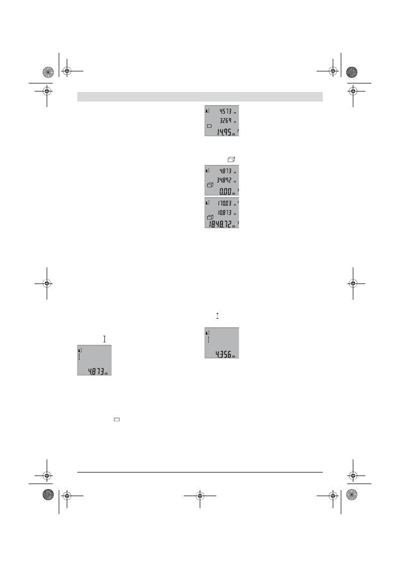
84
| Polski
2 609 140 773 | (4.12.12)
Bosch Power Tools
Przy uruchomionej funkcji pomiaru ciągłego, pomiar rozpo-
czyna się natychmiast po włączeniu funkcji.
Wartość mierzona ukaże się w przeciągu 0,5 do 4 sek. Czas
trwania pomiaru zależy od mierzonej odległości, od warun-
ków świetlnych i refleksu świetlnego obiektu pomiaru. Po za-
kończeniu pomiaru promień lasera wyłączany jest automa-
tycznie.
Jeżeli przez ok. 20 sek. po naprowadzeniu promienia lasera
na cel nie zostanie dokonany pomiar, promień wyłączy się
samoczynnie (oszczędzanie baterii).
Wybór płaszczyzny odniesienia (zob. rys. A)
Przed rozpoczęciem pomiaru możliwy jest wybór między trze-
ma różnymi płaszczyznami odniesienia:
– od tylnej krawędzi urządzenia pomiarowego (np. przez
przyłożenie do ściany),
– przednią krawędzią urządzenia pomiarowego (np. przy po-
miarach od krawędzi stołu),
– środkiem gwintu
14
(np. przy pomiarach przy użyciu staty-
wu).
Wyboru płaszczyzny odniesienia dokonuje się przez kilkakrot-
ne wciskanie przycisku
6
, aż do ukazania na wyświetlaczu po-
żądanej płaszczyzny odniesienia. Po każdym włączeniu urzą-
dzenia pomiarowego automatycznie wyznaczana jest jego tyl-
na krawędź jako płaszczyzna odniesienia.
Podświetlenie wyświetlacza
Podświetlenia wyświetlacza uruchamia się automatycznie – w
zależności od warunków oświetleniowych otoczenia. Jeżeli
po włączeniu podświetlenia wyświetlacza nie zostanie wciś-
nięty żaden przycisk, podświetlenie automatycznie ściemnia
się w celu oszczędzania baterii.
Funkcje pomiaru
Pojedynczy pomiar odległości (zob. rys. B)
Aby dokonać pomiaru odległości należy dotąd naciskać przy-
cisk
9
, dopóki na wyświetlaczu nie ukaże się wskaźnik pomia-
ru odległości .
Aby włączyć laser, a także aby dokonać
pomiaru, należy za każdym razem krótko
nacisnąć przycisk pomiaru
2
.
Wartość zostanie wyświetlona w pasku
wyniku
b
.
W przypadku większej ilości pomiarów odległości, następują-
cych jeden po drugim, ostatnie wyniki pomiarów wyświetlone
zostaną w paskach wartości pomiarowych
a
.
Pomiar powierzchni (zob. rys. C)
Aby dokonać pomiaru powierzchni należy dotąd naciskać
przycisk
3
, dopóki na wyświetlaczu nie ukaże się wskaźnik po-
miaru powierzchni
.
Należy kolejno zmierzyć długość i szerokość, jak w przypadku
pomiaru odległości. Między oboma pomiarami wiązka lasera
jest nieprzerwanie emitowana.
Po zakończeniu drugiego pomiaru, po-
wierzchnia obliczana jest automatycznie i
wyświetlana w pasku wyniku
b
. Wartości
poszczególnych pomiarów wyświetlane
są w paskach wartości pomiarowych
a
.
Pomiar objętości (kubatury) (zob. rys. D)
Aby dokonać pomiaru kubatury, należy dotąd naciskać przy-
cisk
3
, dopóki na wyświetlaczu nie ukaże się wskaźnik pomia-
ru kubatury
.
Następnie należy zmierzyć długość, sze-
rokość i wysokość, tak jak w przypadku
pomiaru odległości. Między wszystkimi
trzema pomiarami wiązka lasera jest
nieprzerwanie emitowana.
Po zakończeniu drugiego pomiaru, kuba-
tura obliczana jest automatycznie i
wyświetlana w pasku wyniku
b
. Wartości
poszczególnych pomiarów wyświetlane
są w paskach wartości pomiarowych
a
.
Wartości przekraczających 999999 m
3
nie da się wyświetlić
– na wyświetlaczu ukazuje się komunikat
„ERROR“
. Obję-
tość, która ma zostać pomierzona należy rozłożyć na kilka po-
miarów pojedynczych. Każdą z wartości należy wyliczyć od-
dzielnie, a następnie zsumować.
Pomiar ciągły (zob. rys. E)
Podczas pomiaru ciągłego urządzenie pomiarowe można
przybliżyć relatywnie do celu, przy czym wartość pomiarowa
aktualizowana jest co 0,5 sekundy. Możliwe jest więc na przy-
kład odsunięcie się od ściany aż do pożądanej odległości, a
aktualną odległość można będzie nadal odczytać.
Aby dokonać pomiaru ciągłego należy dotąd naciskać przy-
cisk
9
, aż na wyświetlaczu nie ukaże się wskaźnik pomiaru cią-
głego . Aby rozpocząć pomiar ciągły, należy wcisnąć przy-
cisk „Pomiar“
2
.
Aktualna wartość pomiarowa zostanie
wyświetlona w pasku wyniku
b
.
Naciśnięcie przycisku pomiar
2
przerywa
pomiar ciągły. W pasku wyniku
b
wyświet-
lona zostanie ostatnio pomierzona war-
tość. Ponowne naciśnięcie przycisku po-
miar
2
wznowi funkcję pomiaru ciągłego.
Funkcja pomiaru ciągłego wyłącza się samoczynnie po 5 min.
W pasku wyniku
b
pozostanie ostatnio pomierzona wartość.
Pośredni pomiar wysokości / Pojedynczy pomiar Pitago-
rasa (zob. rys. F)
Pośredni pomiar wysokości służy do pomiaru odległości, w
sytuacjach, kiedy nie są możliwe pomiary bezpośrednie, gdyż
bieg promienia zakłócony jest przez jakąś przeszkodę, lub gdy
do dyspozycji nie mamy żadnej płaszczyzny mogącej odbić
refleks świetlny. Prawidłowe wyniki mogą zostać tylko wtedy
osiągnięte, gdy wymagane przy danym pomiarze kąty proste
zostaną dokładnie zachowane (twierdzenie Pitagorasa).
Należy zwrócić uwagę na to, aby punkt odniesienia dla danego
pomiaru (np. tylna krawędź urządzenia pomiarowego) przy
wszystkich pomiarach wchodzących w skład danego procesu
OBJ_BUCH-1444-004.book Page 84 Tuesday, December 4, 2012 1:47 PM
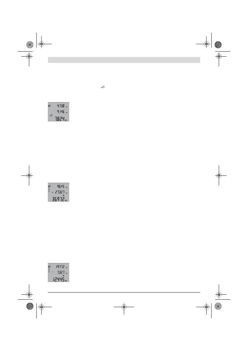
Polski |
85
Bosch Power Tools
2 609 140 773 | (4.12.12)
pomiarowego znajdował się zawsze dokładnie w tym samym
miejscu.
Pomiędzy poszczególnymi pomiarami wiązka lasera pozosta-
nie włączona.
Wciskać przycisk
3
tyle razy, aż na wyświetlaczu nie ukaże się
wskaźnik pojedynczego pomiaru Pitagorasa
.
Zmierzyć, jak w przypadku pomiaru odległości, odcinki
„1“
i
„2“
(w tej kolejności). Należy przy tym zwrócić uwagę, by od-
cinek
„1“
i mierzony odcinek
„X“
tworzyły kąt prosty.
Po zakończeniu ostatniego pomiaru, wy-
nik mierzonego odcinka
„X“
wyświetlany
jest w pasku wyniku
b
. Wartości poszcze-
gólnych pomiarów wyświetlane są w pa-
skach wartości pomiarowych
a
.
Kasowanie wartości mierzonych
Po krótkim naciśnięciu przycisku
4
, kasowana jest we wszyst-
kich trybach pracy ostatnio pomierzona wartość jednostko-
wa. Przez wielokrotne krótkie naciśnięcie przycisku można
kasować wartości jednostkowe w odwrotnej kolejności.
Dodawanie wartości pomiarowych
Aby dodać wartości pomiarowe, należy najpierw przeprowa-
dzić dowolny pomiar. Następnie należy nacisnąć przycisk
plus
8
. Na wyświetlaczu pojawi się symbol
„+“
, oznaczający
potwierdzenie wybranej funkcji.
Aby zsumować kubatury lub powierzchnie, należy po zakoń-
czeniu pomiaru wcisnąć przycisk plus
8
. Na wyświetlaczu, z
lewej strony symbolu dla kubatury/ powierzchni, pojawi się
symbol
„+“
, oznaczający potwierdzenie wybranej funkcji.
Następnie należy przeprowadzić drugi pomiar.
Aby wywołać sumę obu wartości, należy
ponownie wcisnąć przycisk plus
8
. Obli-
czenie wyświetlane jest w paskach warto-
ści pomiarowych
a
, a suma w pasku wyni-
ku
b
.
Po zakończeniu dodawania do wyniku można dodawać kolej-
ne wartości. Przed każdym pomiarem trzeba (za każdym ra-
zem) wcisnąć przycisk plus
8
.
Wskazówki dotyczące dodawania:
– Wartości odległości, powierzchni i kubatury nie można do
siebie dodawać. Przy próbie dodania wartości odległości i
powierzchni (na przykład), po naciśnięciu przycisku plus
8
na wyświetlaczu pojawi się na krótko napis
„ERROR“
. Na-
stępnie urządzenie pomiarowe przechodzi do funkcji po-
miarowej, która była uaktywniona jako ostatnia.
– Dodawany jest zawsze wynik jednego pomiaru (np. war-
tość kubatury), w przypadku pomiarów ciągłych wartość
pomiaru ukazana w pasku wyniku
b
. Dodawanie pojedyn-
czych wartości pomiarowych z pasków
a
nie jest możliwe.
Odejmowanie wartości mierzonych
W celu odejmowania wartości pomiaro-
wych należy wcisnąć przycisk minus
5
, na
wyświetlaczu ukaże się
„–“
. Dalej należy
postępować analogicznie do „Dodawanie
wartości pomiarowych“.
Wskazówki dotyczące pracy
Wskazówki ogólne
Soczewka laserowa
12
i otwór wyjściowy wiązki laserowej
11
nie mogą być zasłonięte podczas pomiaru.
Podczas pomiaru nie wolno poruszać urządzenia pomiarowe-
go (wyjątek stanowi funkcja "Pomiar ciągły". Dlatego zaleca
się, aby w miarę możliwości urządzenie pomiarowe stawiać
na stabilnej płaszczyźnie lub przykładać do stabilnej po-
wierzchni.
Wpływy na zasięg pomiarowy
Zasięg pomiarowy zależy od warunków oświetleniowych i od
refleksu świetlnego obiektu pomiaru. Dla lepszej widoczności
wiązki lasera podczas prac w terenie odkrytym i przy silnym
nasłonecznieniu, należy użyć okularów do pracy z laserem
19
(osprzęt) i tarczy celowniczej
20
(osprzęt), lub zacienić
obiekt pomiaru.
Wpływy na wynik pomiaru
W wyniku uwarunkowanych fizycznie efektów nie można wy-
kluczyć, że wyniki pomiaru niektórych obiektów docelowych
mogą się okazać błędne. Do nich należą:
– przezroczyste obiekty docelowe (np. szkło, woda),
– powierzchnie lustrzane (np. polerowany metal, szkło),
– porowate powierzchnie (np. materiały izolacyjne),
– powierzchnie o silnej fakturze (np. surowy tynk, kamień
naturalny).
W razie potrzeby należy użyć w w/w przypadkach tarczy
celowniczej
20
(osprzęt).
Błędy w pomiarach są możliwe również w przypadku celów
namierzonych z ukosa.
Wpływ na wartość mierzoną mogą mieć też warstwy powie-
trza o różnych temperaturach oraz pośrednio odebrane re-
fleksy.
Kontrola dokładności pomiaru odległości
Dokładność pomiaru odległości można sprawdzić w następu-
jący sposób:
– Należy wybrać odcinek o długości od 1 do 10 m, który nie
będzie się zmieniał i którego długość jest dokładnie znana
(np. szerokość pomieszczenia, otwór drzwiowy). Odcinek
ten musi znajdować się w pomieszczeniu zamkniętym, a
obiekt pomiaru musi być gładki i dobrze odbijać światło.
– Odcinek należy zmierzyć dziesięciokrotnie – raz za razem.
Odchylenie poszczególnych pomiarów od wartości średniej
może wynosić maksymalnie ±2 mm. Pomiary należy protoko-
łować, aby w późniejszym czasie móc porównać ich dokład-
ność.
Praca ze statywem (osprzęt)
Użycie statywu jest konieczne szczególnie w przypadku więk-
szych odległości. Urządzenie pomiarowe można przyśrubo-
wać za pomocą gwintu 1/4"
14
do płytki szybkiego mocowa-
nia statywu
18
lub każdego dostępnego w handlu statywu fo-
tograficznego. Zamocować je za pomocą śruby ustalającej,
znajdującej się na płytce szybkiego mocowania.
Płaszczyzna odniesienia dla pomiarów ze statywem powinna
zostać odpowiednio nastawiona poprzez naciśnięcie przyci-
sku
6
(płaszczyzna odniesienia Gwint).
OBJ_BUCH-1444-004.book Page 85 Tuesday, December 4, 2012 1:47 PM
86
| Polski
2 609 140 773 | (4.12.12)
Bosch Power Tools
Błędy – przyczyny i usuwanie
Urządzenie pomiarowe samo kontroluje
prawidłowe funkcjonowanie podczas każ-
dego z pomiarów. Gdy stwierdzony zosta-
nie defekt, na wyświetlaczu widoczny jest
tylko migający symbol, odzwierciedlony
obok. W tym przypadku, lub, gdy żaden
z wyżej wymienionych kroków nie doprowadził do usunięcia
błędu, urządzenie pomiarowe musi zostać oddane do serwisu
Boscha (za pośrednictwem punktu zakupu).
Konserwacja i serwis
Konserwacja i czyszczenie
Urządzenie pomiarowe należy przechowywać
i transportować tylko w znajdującej się w wyposażeniu stan-
dardowym torbie ochronnej.
Narzędzie pomiarowe należy utrzymywać w czystości.
Nie wolno zanurzać urządzenia pomiarowego w wodzie ani in-
nych cieczach.
Zanieczyszczenia należy usuwać za pomocą wilgotnej, mięk-
kiej ściereczki. Nie używać żadnych środków czyszczących
ani zawierających rozpuszczalnik.
Soczewka odbioru sygnału
12
wymaga takiej samej starannej
pielęgnacji, jak okulary lub soczewka aparatu fotograficzne-
go.
Jeśli urządzenie pomiarowe, mimo starannych metod pro-
dukcji i kontroli uległoby awarii, naprawę powinien przepro-
wadzić autoryzowany serwis elektronarzędzi firmy Bosch. Nie
wolno samemu otwierać urządzenia pomiarowego.
Przy wszystkich zapytaniach i zamówieniach części zamien-
nych, proszę podać koniecznie 10 cyfrowy numer katalogowy
podany na tabliczce znamionowej urządzenia pomiarowego.
W przypadku konieczności naprawy, urządzenie pomiarowe
należy odesłać w futerale
17
.
Obsługa klienta oraz doradztwo dotyczące użyt-
kowania
W punkcie obsługi klienta można uzyskać odpowiedzi na pyta-
nia dotyczące napraw i konserwacji nabytego produktu, a tak-
że dotyczące części zamiennych. Rysunki rozłożeniowe oraz
informacje dotyczące części zamiennych można znaleźć rów-
nież pod adresem:
www.bosch-pt.com
Nasz zespół doradztwa dotyczącego użytkowania odpowie na
wszystkie pytania związane z produktami firmy Bosch oraz ich
osprzętem.
Polska
Robert Bosch Sp. z o.o.
Serwis Elektronarzędzi
Ul. Szyszkowa 35/37
02-285 Warszawa
Tel.: 22 7154460
Faks: 22 7154441
E-Mail: bsc@pl.bosch.com
Infolinia Działu Elektronarzędzi: 801 100900
(w cenie połączenia lokalnego)
E-Mail: elektronarzedzia.info@pl.bosch.com
www.bosch.pl
Usuwanie odpadów
Urządzenia pomiarowe, osprzęt i opakowanie powinny zostać
dostarczone do utylizacji zgodnie z przepisami ochrony
środowiska.
Przyczyna
Usuwanie błędu
Alarm temperatury (f) miga, dokonywanie pomiarów nie
jest już możliwe
Temperatura urządzenia pomiaro-
wego przekroczyła zalecaną war-
tość – między – 10 °C a +50 °C
(w trybie pracy ciągłej do
+40 °C).
Odczekać, aż urządzenie
pomiarowe osiągnie
temperaturę roboczą
Wskazania „ERROR“ na wyświetlaczu
Dodawanie/odejmowanie warto-
ści mierzonych o różnych jednost-
kach miary
Dodawane i odejmo-
wane mogą być tylko
wartości o jednakowych
jednostkach miary
Zbyt ostry kąt między wiązką lase-
ra i celem.
Zwiększyć kąt między
wiązką lasera i celem
Obiekt pomiaru nadmiernie (np.
lustro) lub niedostatecznie (np.
czarny materiał) odbija, wzgl. na-
słonecznienie jest zbyt silne.
Użyć tarczy celowniczej
lasera
20
(osprzęt)
Otwór wyjściowy wiązki laserowej
11
lub soczewka odbioru
12
są
zaparowane (np. pod wpływem
zbyt szybkiej zmiany tem-
peratury).
Wytrzeć za pomocą
miękkiej tkaniny do su-
cha otwór wyjściowy
wiązki laserowej
11
lub
soczewkę odbioru
12
Pomierzona wartość jest większa
niż 999999 m/m
2
/m
3
.
Obliczenie należy rozło-
żyć na kilka etapów
Niepewny wynik pomiaru
Obiekt pomiaru odbija światło w
sposób niewystarczający (np. wo-
da, szkło).
Przykryć obiekt pomiaru
Otwór wyjściowy wiązki laserowej
11
lub soczewka odbioru
12
jest
zakryta.
Odsłonić otwór wyjścio-
wy wiązki laserowej
11
lub soczewkę odbioru
12
Ustawiona została niewłaściwa
płaszczyzna odniesienia
Wybrać odpowiednią do
rodzaju pomiaru płasz-
czyznę
Przeszkoda na drodze wiązki lase-
ra
Plamka lasera musi w ca-
łości znajdować się na
obiekcie docelowym.
Wskazanie nie zmienia się lub urządzenie pomiarowe re-
aguje niewłaściwie na przyciśnięcie przycisku
Błąd oprogramowania
Wyjąć baterie i po po-
nownym ich włożeniu na
nowo uruchomić urzą-
dzenie pomiarowe.
OBJ_BUCH-1444-004.book Page 86 Tuesday, December 4, 2012 1:47 PM
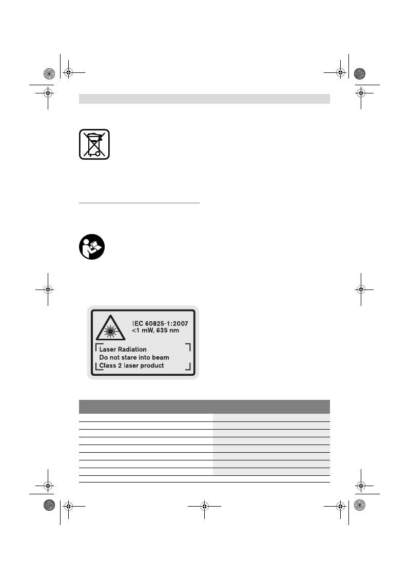
Česky |
87
Bosch Power Tools
2 609 140 773 | (4.12.12)
Urządzeń pomiarowych i akumulatorów/baterii nie wolno wy-
rzucać do odpadów domowych!
Tylko dla państw należących do UE:
Zgodnie z europejską wytyczną
2002/96/WE, niezdatne do użytku urzą-
dzenia pomiarowe, a zgodnie z europejską
wytyczną 2006/66/WE uszkodzone lub zu-
żyte akumulatory/ baterie, należy zbierać
osobno i doprowadzić do ponownego prze-
tworzenia zgodnego z zasadami ochrony środowiska.
Zastrzega się prawo dokonywania zmian.
Česky
Bezpečnostní upozornění
Čtěte a respektujte veškeré pokyny, aby se
s měřícím přístrojem pracovalo bezpečně a
spolehlivě. Nikdy nezpůsobte varovné štít-
ky na měřícím přístroji nerozpoznatelné.
TYTO POKYNY DOBŘE USCHOVEJTE.
Pozor – pokud se použije jiné než zde uvedené ovládací
nebo seřizovací vybavení nebo provedou jiné postupy,
může to vést k nebezpečné expozici zářením.
Měřící přístroj se expeduje s varovným štítkem v ang-
ličtině (v zobrazení měřícího přístroje na grafické stra-
ně označený číslem 15).
Před prvním uvedením do provozu přelepte anglický
text varovného štítku přiloženou samolepkou ve Va-
šem národním jazyce.
Nikdy nesměřujte laserový paprsek na osoby nebo zví-
řata a ani sami se do paprsku laseru nedívejte.
Tento
měřící přístroj vytváří laserové záření třídy 2 podle
IEC 60825-1. Tím můžete osoby oslnit.
Nepoužívejte brýle pro práci s laserem jako ochranné
brýle.
Brýle pro práci s laserem slouží k lepšímu rozpozná-
ní laserového paprsku, ale nechrání před laserovým pa-
prskem.
Nepoužívejte brýle pro práci s laserem jako sluneční
brýle nebo v silničním provozu.
Brýle pro práci s laserem
nenabízejí kompletní ochranu před UV zářením a snižují
vnímání barev.
Měřící přístroj nechte opravit kvalifikovaným odbor-
ným personálem a jen originálními náhradními díly.
Tím
bude zajištěno, že bezpečnost přístroje zůstane zachová-
na.
Nenechte děti používat laserový měřící přístroj bez do-
zoru.
Mohou neúmyslně oslnit osoby.
Nepracujte s měřícím přístrojem v prostředí s nebezpe-
čím výbuchu, v němž se nacházejí hořlavé kapaliny,
plyny nebo prach.
V měřícím přístroji se mohou vytvářet
jiskry, jež zapálí prach nebo plyny.
Popis výrobku a specifikací
Otočte vyklápěcí stranu se zobrazením měřícího přístroje a
nechte tuto stranu během čtení návodu k obsluze otočenou.
Určující použití
Měřící přístroj je určen pro měření vzdáleností, délek, výšek,
rozestupů a k výpočtu ploch a objemů. Měřící přístroj je vhod-
ný pro měření ve vnitřních a venkovních prostorech.
Technická data
Digitální laserový měřič vzdálenosti
GLM 50
Professional
Objednací číslo
3 601 K72 2..
Rozsah měření
0,05 –50 m
A)
Přesnost měření (typicky)
±1,5 mm
B)
Nejmenší zobrazovaná jednotka
1 mm
Provozní teplota
–10 °C...+50 °C
C)
Skladovací teplota
–20 °C...+70 °C
Relativní vlhkost vzduchu max.
90 %
Třída laseru
2
OBJ_BUCH-1444-004.book Page 87 Tuesday, December 4, 2012 1:47 PM
88
| Česky
2 609 140 773 | (4.12.12)
Bosch Power Tools
Zobrazené komponenty
Číslování zobrazených komponent se vztahuje na zobrazení
měřícího přístroje na obrázkové straně.
1
Displej
2
Tlačítko měření
3
Tlačítko měření plochy, objemu a nepřímého měření výš-
ky (Pythagorova věta)
4
Tlačítko vymazání / tlačítko zapnutí-vypnutí **
5
Tlačítko Mínus
6
Tlačítko volby vztažné roviny
7
Upevnění nosného poutka
8
Tlačítko Plus
9
Tlačítko délkového a trvalého měření
10
Kryt přihrádky baterie
11
Výstup laserového paprsku
12
Přijímací čočka
13
Sériové číslo
14
Závit 1/4"
15
Varovný štítek laseru
16
Aretace krytu přihrádky pro baterie
17
Ochranná taška
18
Stativ*
19
Brýle pro práci s laserem *
20
Cílová tabulka laseru*
* Zobrazené nebo popsané příslušenství nepatří do standardní do-
dávky.
** Pro vyvolání rozšiřujících funkcí podržte tlačítko stlačené.
Zobrazované prvky
a
Řádky naměřených hodnot
b
Výsledkový řádek
c
Měřicí funkce
d
Laser zapnutý
e
Vztažná rovina měření
f
Výstraha teploty
g
Výstraha baterie
h
Ukazatel chyby
„ERROR“
Montáž
Nasazení/výměna baterií
Pro provoz měřicího přístroje je doporučeno používání alka-
licko-manganových baterií nebo akumulátorů.
S akumulátory 1,2 V je možných méně měření než s bateriemi
1,5 V.
Pro otevření krytu přihrádky pro baterie
10
stlačte aretaci
16
a kryt přihrádky pro baterie odejměte. Vložte baterie resp.
Typ laseru
635 nm, <1 mW
Průměr laserového paprsku (při 25 °C) ca.
– ve vzdálenosti 10 m
– ve vzdálenosti 50 m
6 mm
35 mm
Vypínací automatika po ca.
– pro laser
– pro měřící přístroj (bez měření)
20 s
5 min
Baterie
Akumulátorové články
2 x 1,5 V LR03 (AAA)
2 x 1,2 V HR03 (AAA)
Životnost baterií ca.
– jednotlivá měření
– trvalé měření
10000
D)
2,5 h
D)
Hmotnost podle EPTA-Procedure 01/2003
0,14 kg
Rozměry
53 x 114 x 30 mm
Stupeň krytí
IP 54 (ochrana proti prachu a stříkající vodě)
Digitální laserový měřič vzdálenosti
GLM 50
Professional
A) Dosah je větší, čím lépe se světlo laseru odrazí od povrchu cíle (rozptýlené, nikoli zrcadlené) a čím je jasnější bod laseru vůči světlosti okolí (vnitřní
prostory, šero). Při nepříznivých podmínkách (např. měření venku za silného slunečního záření) může být nutné použití cílové tabulky.
B) Při měřeních od zadní hrany měřicího přístroje. Při nepříznivých podmínkách jako např. silné sluneční záření nebo špatně odrážející povrch činí ma-
ximální odchylka
±
10 mm na 50 m. Při příznivých podmínkách je třeba počítat s vlivem
±
0,05 mm/m.
C) Ve funkci trvalé měření činí max. provozní teplota +40
°C
.
D) S akumulátorovými články 1,2 V je možných méně měření než s bateriemi 1,5 V. Uvedená životnost baterií se vztahuje na měření bez osvětlení dis-
pleje.
K jednoznačné identifikaci Vašeho měřícího přístroje slouží sériové číslo
13
na typovém štítku.
Měření délek
Trvalé měření
Měření ploch
Měření objemu
Jednoduché měření podle Pythagorovy věty
OBJ_BUCH-1444-004.book Page 88 Tuesday, December 4, 2012 1:47 PM
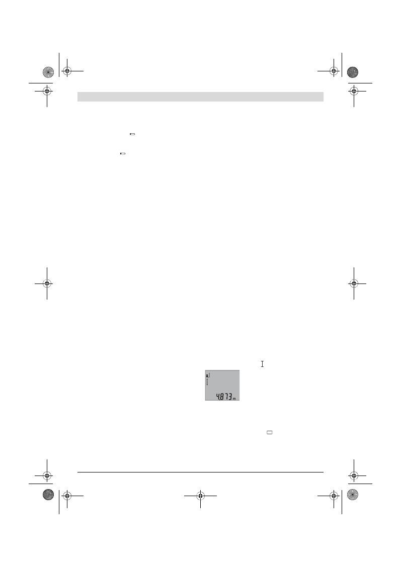
Česky |
89
Bosch Power Tools
2 609 140 773 | (4.12.12)
akumulátory. Dbejte přitom na správnou polaritu podle vyob-
razení na vnitřní straně přihrádky pro baterie.
Při vkládání baterií resp. akumulátorů dbejte na správnou po-
laritu podle vyobrazení v přihrádce pro baterie.
Objeví-li se symbol baterie
poprvé na displeji, pak je mož-
ných ještě minimálně 100 jednotlivých měření. Funkce trvalé-
ho měření je deaktivovaná.
Pokud symbol baterie
bliká, musíte baterie resp. akumulá-
torové články vyměnit. Měření už nejsou možná.
Nahraďte vždy všechny baterie resp. akumulátory současně.
Použijte pouze baterie nebo akumulátory jednoho výrobce a
stejné kapacity.
Pokud měřící přístroj delší dobu nepoužíváte, vyjměte
z něj baterie resp. akumulátory.
Baterie a akumulátory
mohou pří delším skladování korodovat a samy se vybít.
Provoz
Uvedení do provozu
Neponechávejte zapnutý měřící přístroj bez dozoru a
po používání jej vypněte.
Mohly by být laserovým pa-
prskem oslněny jiné osoby.
Chraňte měřící přístroj před vlhkem a přímým sluneč-
ním zářením.
Nevystavujte měřící přístroj žádným extrémním teplo-
tám nebo teplotním výkyvům.
Nenechávejte jej např.
delší dobu ležet v autě. Při větších teplotních výkyvech ne-
chte měřící přístroj nejprve vytemperovat, než jej uvedete
do provozu. Při extrémních teplotách nebo teplotních vý-
kyvech může být omezena přesnost přístroje.
Vyhněte se prudkým nárazům nebo pádům měřícího
přístroje.
Po silných vnějších účincích na měřící přístroj
byste měli před další prací vždy provést kontrolu přesnosti
(viz „Kontrola přesnosti měření vzdálenosti“, strana 91).
Zapnutí – vypnutí
Pro
zapnutí
měřícího přístroje máte následující možnosti:
– Stisknutí tlačítka zapnutí-vypnutí
4
: měřící přístroj se za-
pne a nachází se ve funkci měření délky. Laser se nezapne.
– Stisknutí tlačítka měření
2
: měřicí přístroj a laser se za-
pnou. Měřicí přístroj se nachází ve funkci měření délky.
Nesměrujte laserový paprsek na osoby nebo zvířata a
nedívejte se sami do něj a to ani z větší vzdálenosti.
Pro
vypnutí
měřícího přístroje zatlačte dlouze na tlačítko za-
pnutí-vypnutí
4
.
Nestiskne-li ca. 5 min na měřícím přístroji žádné tlačítko, pak
se kvůli šetření baterií měřící přístroj automaticky vypne.
Postup měření
Po zapnutí prostřednictvím stisknutí tlačítka měření
2
se mě-
řicí přístroj vždy nachází ve funkci měření délky. Jiné měřicí
funkce můžete nastavit stiskem příslušného funkčního tlačít-
ka (viz „Měřící funkce“, strana 89).
Jako vztažná rovina pro měření je po zapnutí zvolena zadní
hrana měřícího přístroje. Stlačováním tlačítka vztažné roviny
6
můžete vztažnou rovinu změnit (viz „Volba vztažné roviny“,
strana 89).
Přiložte měřicí přístroj zvolenou vztažnou rovinou na požado-
vaný výchozí bod měření (např. stěnu).
Pro zapnutí laserového paprsku zatlačte krátce na tlačítko
měření
2
.
Nesměrujte laserový paprsek na osoby nebo zvířata a
nedívejte se sami do něj a to ani z větší vzdálenosti.
Zamiřte paprskem laseru na cílovou plochu. Pro spuštění mě-
ření znovu krátce zatlačte na tlačítko měření
2
.
Ve funkci trvalé měření začíná měření ihned po zapnutí funk-
ce.
Naměřená hodnota se objeví typicky během 0,5 s a nejpozdě-
ji po 4 s. Doba měření závisí na vzdálenosti, světelných pomě-
rech a odrazových vlastnostech cílové plochy. Po ukončení
měření se laser automaticky vypne.
Pokud ca. 20 s po zaměření nenásleduje žádné měření, papr-
sek laseru se kvůli šetření baterií automaticky vypne.
Volba vztažné roviny (viz obr. A)
Pro měření můžete volit mezi třemi různými vztažnými rovina-
mi:
– zadní hranou měřicího přístroje (např. při přiložení na stě-
ny),
– přední hranou měřícího přístroje (např. při měření od hra-
ny stolu),
– středem závitu
14
(např. pro měření se stativem).
Pro změnu vztažné roviny stiskněte tlačítko
6
tolikrát, až se na
displeji zobrazí požadovaná vztažná rovina. Po každém za-
pnutí měřícího přístroje je přednastavena jako vztažná rovina
zadní hrana měřícího přístroje.
Osvětlení displeje
Osvětlení displeje se automaticky aktivuje podle světelnosti
okolí. Nenásleduje-li po zapnutí osvětlení displeje stisk žádné-
ho tlačítka, bude kvůli šetření baterií ztlumeno.
Měřící funkce
Jednoduché měření délky (viz obr. B)
Pro měření délky stiskněte tolikrát tlačítko
9
, až se na displeji
objeví ukazatel měření délky .
Pro zapnutí laseru a pro měření pokaždé
jednou krátce stiskněte tlačítko měření
2
.
Naměřená hodnota se zobrazí ve výsled-
kovém řádku
b
.
Při několika měřeních délek za sebou se
výsledky posledních měření zobrazí v řádcích naměřených
hodnot
a
.
Měření plochy (viz obr. C)
Pro měření plochy stiskněte tolikrát tlačítko
3
, až se na disple-
ji objeví ukazatel měření plochy
.
Následně změřte po sobě délku a šířku jako při měření délky.
Mezi oběma měřeními zůstává paprsek laseru zapnutý.
OBJ_BUCH-1444-004.book Page 89 Tuesday, December 4, 2012 1:47 PM
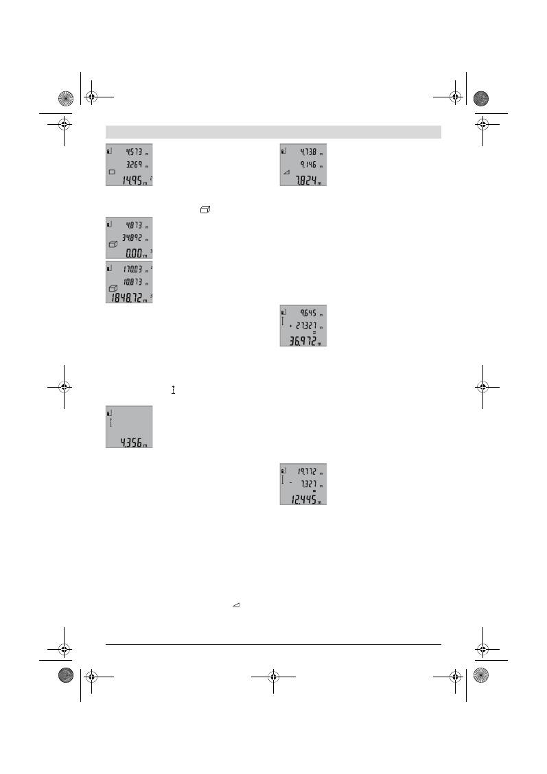
90
| Česky
2 609 140 773 | (4.12.12)
Bosch Power Tools
Po zakončení druhého měření se plocha
automaticky vypočítá a zobrazí ve výsled-
kovém řádku
b
. Jednotlivé naměřené
hodnoty jsou v řádcích naměřených hod-
not
a
.
Měření objemu (viz obr. D)
Pro měření objemu stiskněte tolikrát tlačítko
3
, až se na dis-
pleji objeví ukazatel měření objemu
.
Následně změřte po sobě délku, šířku a
výšku jako při měření délky. Mezi těmito
třemi měřeními zůstává paprsek laseru
zapnutý.
Po zakončení třetího měření se objem au-
tomaticky vypočítá a zobrazí ve výsled-
kovém řádku
b
. Jednotlivé naměřené
hodnoty jsou v řádcích naměřených hod-
not
a
.
Hodnoty přes 999999 m
3
nelze zobrazit, na displeji se objeví
„ERROR“
. Rozdělte měřený objem na dílčí měření, jejichž
hodnoty vypočítáte odděleně a poté sloučíte.
Trvalé měření (viz obr. E)
Při trvalém měření lze měřícím přístrojem pohybovat relativ-
ně vůči cíli, přičemž naměřená hodnota se ca. každých 0,5 s
aktualizuje. Můžete se např. vzdalovat od stěny až do požado-
vané vzdálenosti, aktuální hodnota je neustále čitelná.
Pro trvalé měření stiskněte tlačítko
9
, až se na displeji objeví
ukazatel trvalého měření . Pro start trvalého měření stiskně-
te tlačítko měření
2
.
Aktuální naměřená hodnota se zobrazuje
ve výsledkovém řádku
b
.
Stisknutím tlačítka měření
2
trvalé měření
ukončíte. Poslední naměřená hodnota se
zobrazí ve výsledkovém řádku
b
. Novým
stiskem tlačítka měření
2
startuje trvalé
měření znovu.
Trvalé měření se po 5 min automaticky vypne. Poslední namě-
řená hodnota zůstane zobrazena ve výsledkovém řádku
b
.
Nepřímé měření výšek / Jednoduché měření podle Pytha-
gorovy věty (viz obr. F)
Nepřímé měření výšky slouží pro zjištění vzdáleností, které
nelze měřit přímo, protože průchodu paprsku brání překážka
nebo není k dispozici žádná cílová plocha pro odraz. Správ-
ných výsledků se dosáhne jen tehdy, pokud se přesně dodrží
u příslušného měření vyžadované pravé úhly (Pythagorova vě-
ta).
Dbejte na to, aby vztažný bod měření (např. zadní hrana měři-
cího přístroje) zůstal u všech jednotlivých měření během pro-
cesu měření na přesně stejném místě.
Mezi jednotlivými měřeními zůstává paprsek laseru zapnutý.
Stiskněte tolikrát tlačítko
3
, až se na displeji objeví ukazatel
pro jednoduché měření podle Pythagorovy věty
.
Změřte jako u měření délky úsečky
„1“
a
„2“
v tomto pořadí.
Dbejte na to, aby byl mezi úsečkou
„1“
a hledanou úsečkou
„X“
pravý úhel.
Po skončení posledního měření se zobra-
zí výsledek pro hledanou úsečku
„X“
ve
výsledkovém řádku
b
. Jednotlivé namě-
řené hodnoty jsou v řádcích naměřených
hodnot
a
.
Vymazání naměřené hodnoty
Krátkým stlačením tlačítka
4
můžete ve všech funkcích měře-
ní smazat naposledy zjištěnou jednotlivou naměřenou hodno-
tu. Vícenásobným krátkým stlačením tlačítka se v opačném
pořadí smažou jednotlivé naměřené hodnoty.
Sčítání naměřených hodnot
Pro sčítání naměřených hodnot nejprve proveďte libovolné
měření. Poté stiskněte tlačítko Plus
8
. Na displeji se pro potvr-
zení objeví
„+“
.
Pro sčítání objemu nebo plochy stiskněte po prvním uzavře-
ném procesu měření tlačítko Plus
8
. Na displeji se pro potvr-
zení objeví
„+“
nalevo od symbolu objemu/plochy.
Potom proveďte druhé měření.
Pro zjištění součtu obou měření stiskněte
ještě jednou tlačítko Plus
8
. Výpočet se
zobrazí v řádcích naměřených hodnot
a
,
součet je ve výsledkovém řádku
b
.
Po výpočtu součtu lze k tomuto výsledku
přičítat další naměřené hodnoty, pokud
se před měřením pokaždé stiskne tlačítko Plus
8
.
Upozornění ke sčítání:
– Hodnoty délky, plochy a objemu nelze smíšeně přičítat.
Budou-li se sčítat např. hodnota délky a hodnota plochy,
objeví se při stisku tlačítka Plus
8
na displeji krátce
„ERROR“
. Poté se měřicí přístroj přepne do naposledy ak-
tivní měřicí funkce.
– Pokaždé se přičte výsledek měření (např. hodnota obje-
mu), u trvalého měření naměřená hodnota zobrazená ve
výsledkovém řádku
b
. Sčítání jednotlivých naměřených
hodnot z řádků naměřených hodnot
a
není možné.
Odečtení naměřené hodnoty
Pro odčítání naměřených hodnot stiskně-
te tlačítko Mínus
5
, pro potvrzení se na
displeji objeví
„–“
. Další postup je analo-
gický ke „Sčítání naměřených hodnot“.
Pracovní pokyny
Všeobecná upozornění
Přijímací čočka
12
a výstup laserového paprsku
11
nesmějí
být při měření zakryty.
Měřicí přístroj se nesmí během měření pohybovat (s výjimkou
funkce trvalého měření). Přiložte proto měřicí přístroj pokud
možno na pevnou dorazovou nebo dosedací plochu.
Vlivy na rozsah měření
Rozsah měření závisí na světelných poměrech a odrazových
vlastnostech cílové plochy. Pro lepší viditelnost laserového
paprsku při práci venku a při silném slunečním svitu používej-
te brýle pro práci s laserem
19
(příslušenství) a cílovou tabul-
ku laseru
20
(příslušenství) nebo cílovou plochu zatemněte.
OBJ_BUCH-1444-004.book Page 90 Tuesday, December 4, 2012 1:47 PM
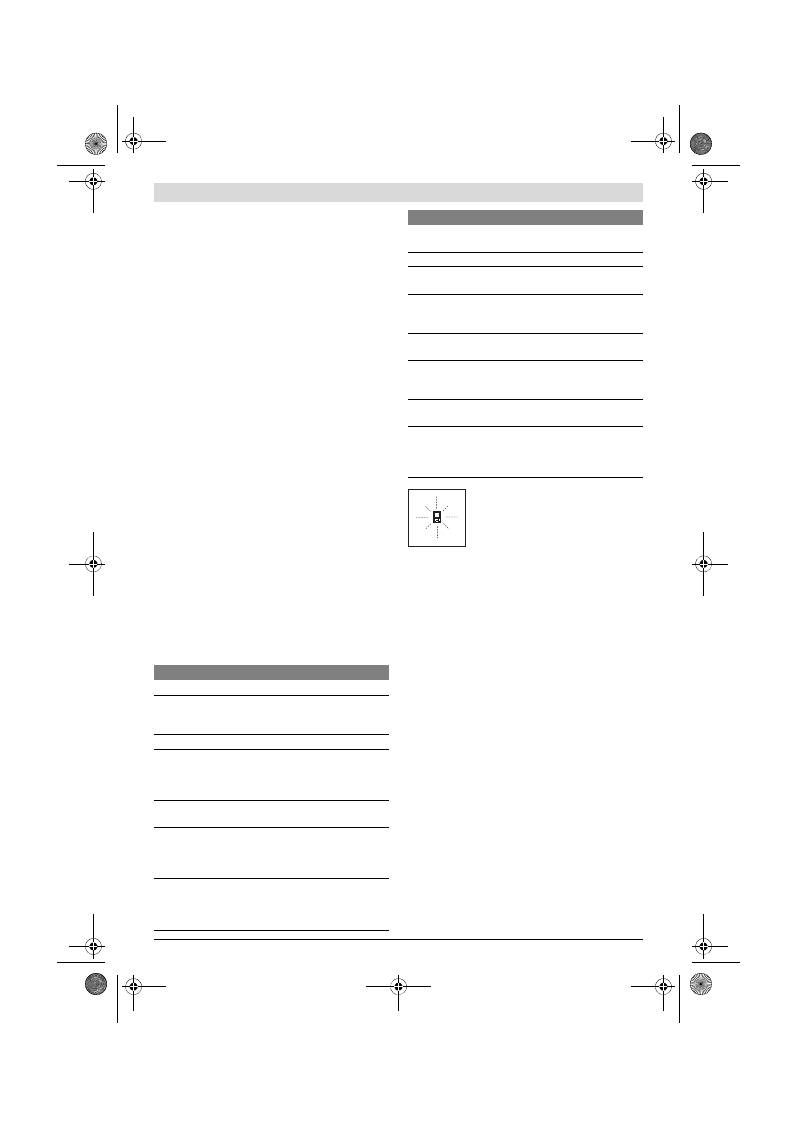
Česky |
91
Bosch Power Tools
2 609 140 773 | (4.12.12)
Vlivy na výsledek měření
Na základě fyzikálních účinků nelze vyloučit, že při měření na
různých površích nedojde k chybným měřením. K tomu nále-
žejí:
– transparentní povrchy (např. sklo, voda),
– lesknoucí se povrchy (např. leštěný kov, sklo),
– porézní povrchy (např. izolační materiály),
– strukturované povrchy (např. hrubá omítka, přírodní ká-
men).
Na těchto površích případně použijte cílovou tabulku laseru
20
(příslušenství).
Chybná měření jsou kromě toho možná na šikmo zaměřených
cílových plochách.
Naměřenou hodnotu mohou rovněž ovlivnit vrstvy vzduchu s
různou teplotou nebo nepřímo přijaté odrazy.
Kontrola přesnosti měření vzdálenosti
Přesnost měření vzdálenosti můžete zkontrolovat takto:
– Zvolte nějakou v čase neměnnou měřenou vzdálenost dél-
ky od ca. 1 do 10 m, jejíž délka je Vám přesně známa (např.
šířka místnosti, otvor dveří). Měřená vzdálenost musí ležet
v interiéru, cílová plocha měření musí být hladká a dobře
odrážející.
– Změřte vzdálenost 10-krát za sebou.
Odchylka jednotlivých měření od střední hodnoty smí činit
maximálně ±2 mm. Měření zaprotokolujte, abyste mohli
přesnost později porovnat.
Práce se stativem (příslušenství)
Použití stativu je zvlášť nutné u větších vzdáleností. Měřící pří-
stroj nasaďte závitem 1/4"
14
na rychlovýměnnou desku sta-
tivu
18
nebo běžného fotostativu. Pevně jej přišroubujte po-
mocí zajišťovacího šroubu rychlovýměnné desky.
Adekvátně nastavte vztažnou rovinu pro měření se stativem
stlačováním tlačítka
6
(vztažná rovina závit).
Chyby – příčiny a nápomoc
Měřící přístroj hlídá správnou funkci při kaž-
dém měření. Pokud je zjištěna závada, bliká
na displeji vedle stojící symbol. V tom pří-
padě nebo když nahoře uvedená ná-
pomocná opatření nemohou chybu odstra-
nit, předejte měřící přístroj přes Vašeho ob-
chodníka do zákaznického servisu Bosch.
Údržba a servis
Údržba a čištění
Uskladňujte a převážejte měřící přístroj pouze v dodávané
ochranné tašce.
Udržujte měřící přístroj vždy čistý.
Měřící přístroj neponořujte do vody nebo jiných kapalin.
Nečistoty otřete vlhkým, měkkým hadříkem. Nepoužívejte
žádné čistící prostředky a rozpouštědla.
Pečujte zvláště o přijímací čočku
12
se stejnou pečlivostí, s ja-
kou se musí zacházet s brýlemi nebo čočkou fotoaparátu.
Pokud by došlo přes pečlivou výrobu a zkušební metody u mě-
řícího přístroje někdy k výpadku, nechte opravu provést v au-
torizovaném servisu pro elektronářadí Bosch. Měřící přístroj
sami neotvírejte.
Při všech dotazech a objednávkách náhradních dílů nezbytně
prosím uvádějte 10-místné objednací číslo podle typového
štítku měřícího přístroje.
V případě opravy zašlete měřící přístroj v ochranné tašce
17
.
Zákaznická a poradenská služba
Zákaznická služba zodpoví Vaše dotazy k opravě a údržbě Va-
šeho výrobku a též k náhradním dílům. Technické výkresy a in-
formace k náhradním dílům naleznete i na:
www.bosch-pt.com
Příčina
Řešení
Výstraha teploty (f) bliká, měření není možné
Měřící přístroj je mimo provozní
teplotu od – 10 °C do +50 °C (ve
funkci trvalé měření do +40 °C).
Vyčkejte až měřící pří-
stroj dosáhne provozní
teploty
Ukazatel „ERROR“ na displeji
Sčítání/odčítání naměřených hod-
not s rozdílnými měrnými jednot-
kami
Sčítejte/odečítejte jen
naměřené hodnoty se
stejnými měrnými jed-
notkami
Úhel mezi paprskem laseru a cílem
je příliš ostrý.
Zvětšete úhel mezi pa-
prskem laseru a cílem
Cílová plocha odráží příliš silně
(např. zrcadlo) ev. příliš slabě (na-
př. černá látka) nebo je okolní
světlo příliš silné.
Použijte cílovou tabulku
laseru
20
(příslušenství)
Výstup laserového paprsku
11
ev.
přijímací čočka
12
jsou orosené
(např. kvůli rychlé změně teploty).
Měkkým hadříkem vytře-
te do sucha výstup lase-
rového paprsku
11
ev.
přijímací čočku
12
Vypočtená hodnota je větší než
999999 m/m
2
/m
3
.
Výpočet rozdělte do jed-
notlivých kroků
Nepřijatelný výsledek měření
Cílová plocha neodráží jedno-
značně (např. voda, sklo).
Cílovou plochu zakryjte
Výstup laserového paprsku
11
ev.
přijímací čočka
12
jsou zakryté.
Výstup laserového pa-
prsku
11
ev. přijímací
čočku
12
odkryjte
Nastavena špatná vztažná rovina
Vztažnou rovinu zvolte
vhodně k měření
Překážka v dráze paprsku laseru
Bod laseru musí kom-
pletně ležet na cílové
ploše.
Ukazatel zůstává nezměněný nebo měřicí přístroj reagu-
je na stisk tlačítka neočekávaně
Chyba v softwaru
Odejměte baterie a po
novém vložení měřicí
přístroj znovu nastartuj-
te.
Příčina
Řešení
OBJ_BUCH-1444-004.book Page 91 Tuesday, December 4, 2012 1:47 PM
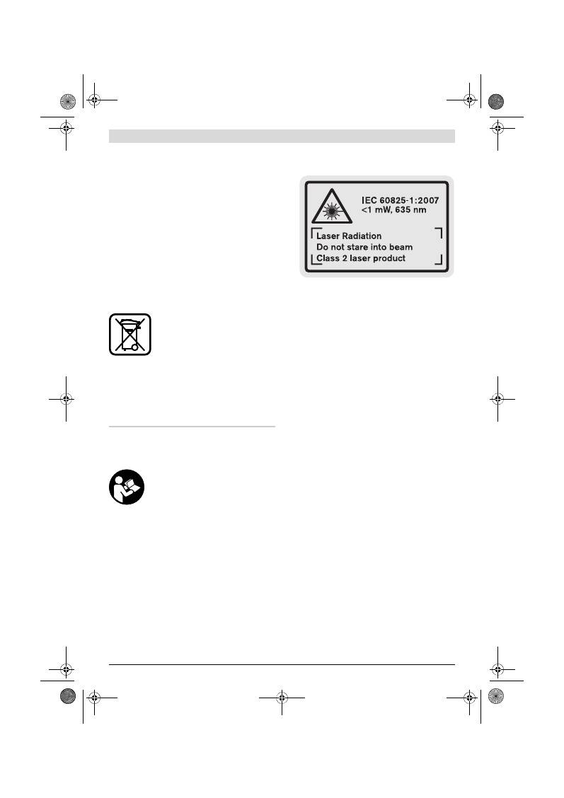
92
| Slovensky
2 609 140 773 | (4.12.12)
Bosch Power Tools
Tým poradenské služby Bosch Vám rád pomůže při otázkách
k našim výrobkům a jejich příslušenství.
Czech Republic
Robert Bosch odbytová s.r.o.
Bosch Service Center PT
K Vápence 1621/16
692 01 Mikulov
Tel.: 519 305700
Fax: 519 305705
E-Mail: servis.naradi@cz.bosch.com
www.bosch.cz
Zpracování odpadů
Měřící přístroje, příslušenství a obaly by měly být dodány k
opětovnému zhodnocení nepoškozujícímu životní prostředí.
Neodhazujte měřicí přístroje a akumulátory/baterie do do-
movního odpadu!
Pouze pro země EU:
Podle evropské směrnice 2002/96/ES mu-
sejí být neupotřebitelné měřící přístroje a
podle evropské směrnice 2006/66/ES vad-
né nebo opotřebované akumu-
látory/baterie rozebrané shromážděny a
dodány k opětovnému zhodnocení nepo-
škozujícímu životní prostředí.
Změny vyhrazeny.
Slovensky
Bezpečnostné pokyny
Aby ste mohli s týmto meracím prístrojom
pracovať bez ohrozenia a bezpečne, musí-
te si prečítať a dodržiavať všetky pokyny.
Nikdy neporušte identifikovateľnosť vý-
stražných značiek na meracom prístroji.
TIETO POKYNY SI DOBRE USCHOVAJTE.
Buďte opatrný – ak používate iné ako tu uvedené ob-
služné a aretačné prvky alebo volíte iné postupy. Môže
to mať za následok nebezpečnú expozíciu žiarenia.
Tento merací prístroj sa dodáva s výstražným štítkom v
anglickom jazyku (na grafickej strane tohto Návodu je
na obrázku merací prístroj označený číslom 15).
Predtým ako začnete produkt prvýkrát používať, pre-
lepte anglický text výstražného štítka dodanou nálep-
kou v jazyku Vašej krajiny.
Nesmerujte laserový lúč na osoby ani na zvieratá, ani
sami sa nepozerajte do laserového lúča.
Tento merací
prístroj vyrába laserové žiarenie laserovej triedy 2 podľa
normy IEC 60825-1. Pri nesprávnom zaobchádzaní by
mohlo dôjsť k oslepeniu osôb.
Nepoužívajte laserové okuliare ako ochranné okuliare.
Laserové okuliare slúžia na lepšie zviditelnenie laserového
lúča, pred laserovým žiarením však nechránia.
Nepoužívajte laserové okuliare ako slnečné okuliare
alebo ako ochranné okuliare v cestnej doprave.
Lasero-
vé okuliare neposkytujú úplnú ochranu pred ultrafialovým
žiarením a znižujú vnímanie farieb.
Merací prístroj nechávajte opravovať len kvalifikova-
nému personálu, ktorý používa originálne náhradné sú-
čiastky.
Tým sa zaručí, že bezpečnosť meracieho prístroja
zostane zachovaná.
Zabráňte tomu, aby tento laserový merací prístroj
mohli bez dozoru použiť deti.
Mohli by neúmyselne osle-
piť iné osoby.
Nepracujte s týmto meracím prístrojom v prostredí
ohrozenom výbuchom, v ktorom sa nachádzajú horľavé
kvapaliny, plyny alebo horľavý prípadne výbušný
prach.
V tomto meracom prístroji sa môžu vytvárať iskry,
ktoré by mohli uvedený prach alebo výpary zapáliť.
Popis produktu a výkonu
Vyklopte si láskavo vyklápaciu stranu s obrázkami meracieho
prístroja a nechajte si ju vyklopenú po celý čas, keď čítate ten-
to Návod na používanie.
Používanie podľa určenia
Tento merací prístroj je určený na meranie vzdialeností,
dĺžok, výšok, odstupov a na výpočet plôch a objemov. Tento
merací prístroj je vhodný na meranie rozmerov v rámci
vnútorných aj vonkajších objektov.
OBJ_BUCH-1444-004.book Page 92 Tuesday, December 4, 2012 1:47 PM
Slovensky |
93
Bosch Power Tools
2 609 140 773 | (4.12.12)
Technické údaje
Vyobrazené komponenty
Číslovanie jednotlivých zobrazených komponentov sa vzťahu-
je na vyobrazenie meracieho prístroja na grafickej strane toh-
to Návodu na používanie.
1
Displej
2
Tlačidlo meranie
3
Tlačidlo pre meranie plochy, objemu a pre nepriame me-
rania výšky (podľa Pytagorovej vety)
4
Vymazávacie tlačidlo / tlačidlo vypínača **
5
Tlačidlo Mínus
6
Tlačidlo Voľba vzťažnej roviny
7
Upevňovací otvor pre slučku na nosenie
8
Tlačidlo Plus
9
Tlačidlo merania dĺžky a trvalého merania
10
Viečko priehradky na batérie
11
Výstup laserového žiarenia
12
Prijímacia šošovka
13
Sériové číslo
14
Závit 1/4"
15
Výstražný štítok laserového prístroja
16
Aretácia veka priehradky na batérie
17
Ochranná taška
18
Statív*
19
Okuliare na zviditeľnenie laserového lúča*
20
Laserová cieľová tabuľka*
* Zobrazené alebo popísané príslušenstvo nepatrí do základnej vý-
bavy produktu.
** Podržte tlačidlo v stlačenej polohe na vyvolanie ďalších rozširu-
júcich funkcií.
Digitálny laserový diaľkomer
GLM 50
Professional
Vecné číslo
3 601 K72 2..
Merací rozsah
0,05 –50 m
A)
Presnosť merania (typicky)
±1,5 mm
B)
Minimálna indikovaná jednotka
1 mm
Prevádzková teplota
–10 °C...+50 °C
C)
Skladovacia teplota
–20 °C...+70 °C
Relatívna vlhkosť vzduchu max.
90 %
Laserová trieda
2
Typ lasera
635 nm, <1 mW
Priemer laserového lúča (pri teplote 25 °C) cca
– vo vzdialenosti 10 m
– vo vzdialenosti 50 m
6 mm
35 mm
Vypínacia automatika po cca
– Laser
– Merací prístroj (bez merania)
20 s
5 min
Batérie
Akumulátorové články
2 x 1,5 V LR03 (AAA)
2 x 1,2 V HR03 (AAA)
Životnosť batérií cca
– Jednotlivé merania
– Trvalé meranie
10000
D)
2,5 h
D)
Hmotnosť podľa EPTA-Procedure 01/2003
0,14 kg
Rozmery
53 x 114 x 30 mm
Druh ochrany
IP 54 (ochrana proti prachu a proti striekajúcej vode)
A) Dosah prístroja je tým väčší, čím lepšie sa laserové svetlo odráža od povrchovej plochy cieľa (rozptýlené, nie zrkadliace) a čím je laserový bod v po-
rovnaní s jasom okolia svetlejší (vnútorné priestory, pri stmievaní). Za nepriaznivých podmienok (napr. pri meraní vonku pri silnom slnečnom žiarení)
sa môže ukázať potrebné použitie cieľovej tabuľky.
B) Pri meraniach od zadnej strany meracieho prístroja. Za nepriaznivých vonkajších podmienok, ako napr. za silného slnečného žiarenia alebo v prípa-
de zle odrážajúcej povrchovej plochy je maximálna odchýlka
±
10 mm na 50 m. Za priaznivých podmienok treba počítať s rozpätím odchýlky
±
0,05 mm/m.
C) Vo funkcii Trvalé meranie je maximálna prevádzková teplota +40
°C
.
D) Pri použití akumulátorových článkov s napätím 1,2 V je možné vykonať menej meraní ako pomocou batérií s napätím 1,5 V. Uvedená doba životnosti
batérií sa vzťahuje na merania uskutočnené bez osvetlenia displeja.
Na jednoznačnú identifikáciu Vášho meracieho prístroja slúži sériové číslo
13
na typovom štítku.
OBJ_BUCH-1444-004.book Page 93 Tuesday, December 4, 2012 1:47 PM

94
| Slovensky
2 609 140 773 | (4.12.12)
Bosch Power Tools
Zobrazovacie (indikačné) prvky
a
Riadky pre namerané hodnoty
b
Riadok pre výsledok
c
Meracie funkcie
d
Laser zapnutý
e
Vzťažná rovina merania
f
Výstraha nevhodnej teploty
g
Výstraha slabej batérie
h
Indikácia poruchy
„ERROR“
Montáž
Vkladanie/výmena batérií
Pri prevádzke tohto meracieho prístroja odporúčame použí-
vanie alkalicko-mangánových batérií alebo akumulátorových
článkov.
Pomocou akumulátorových článkov s napätím 1,2 V je možné
vykonať menej meraní ako pomocou batérií s napätím 1,5 V.
Ak chcete otvoriť viečko priehradky na batérie
10
, zatlačte na
aretáciu
16
a viečko priehradky na batérie demontujte. Vložte
príslušné batérie resp. akumulátorové články. Dajte pritom
pozor na správne pólovanie podľa vyobrazenia na vnútornej
strane priehradky na batérie.
Pri vkladaní batérií resp. akumulátorových článkov dávajte
pozor na správne pólovanie podľa obrázka, ktorý sa nachádza
v priehradke na batérie.
Od okamihu, keď sa na displeji prvýkrát objaví symbol Baté-
ria,
môžete uskutočniť ešte minimálne 100 meraní. Fun-
kcia Trvalé meranie je deaktivovaná.
Keď symbol Batéria
bliká, treba batérie resp. akumuláto-
rové články vymeniť. Ďalšie merania už nie sú možné.
Vymieňajte vždy všetky batérie, resp. všetky akumulátorové
články súčasne. Pri jednej výmene používajte len batérie jed-
ného výrobcu a vždy také, ktoré majú rovnakú kapacitu.
Keď merací prístroj dlhší čas nepoužívate, vyberte z
neho batérie, resp. akumulátorové články.
Počas dlh-
šieho skladovania by mohli batérie alebo akumulátorové
články korodovať a mohli by sa samočinne vybíjať.
Používanie
Uvedenie do prevádzky
Nenechávajte zapnutý merací prístroj bez dozoru a po
použití merací prístroj vždy vypnite.
Laserový lúč by mo-
hol oslepiť iné osoby.
Merací prístroj chráňte pred vlhkom a pred priamym sl-
nečným žiarením.
Merací prístroj nevystavujte extrémnym teplotám ani
žiadnemu kolísaniu teplôt.
Nenechávajte ho odložený
dlhší čas napr. v motorovom vozidle. V prípade väčšieho
rozdielu teplôt nechajte najprv merací prístroj pred jeho
použitím temperovať na teplotu prostredia, v ktorom ho
budete používať. Pri extrémnych teplotách alebo v prípade
kolísania teplôt môže byť negatívne ovplyvnená precíznosť
meracieho prístroja.
Zabráňte prudkým nárazom alebo pádom meracieho
prístroja.
V prípade intenzívnejšieho vonkajšieho zásahu
na merací prístroj by ste mali predtým, ako budete pokra-
čovať v práci, vždy vykonať skúšku presnosti (pozri „Kon-
trola presnosti merania vzdialenosti“, strana 96).
Zapínanie/vypínanie
Ak chcete merací prístroj
zapnúť
, máte na výber nasledujúce
možnosti:
– Stlačte tlačidlo vypínača
4
: Merací prístroj sa zapne a bude
sa nachádzať vo funkcii Meranie dĺžky. Laser sa nezapne.
– Stlačte tlačidlo Meranie
2
: Merací prístroj a laser sa zapnú.
Merací prístroj sa nachádza vo funkcii Meranie dĺžky.
Nesmerujte laserový lúč na osoby ani na zvieratá, ani sa
sami nepozerajte do laserového lúča, dokonca ani z
vačšej vzdialenosti.
Ak chcete merací prístroj
vypnúť
, stlačte na dlhšiu dobu tla-
čidlo vypínača
4
.
Ak sa počas cca 5 min. nestlačí žiadne tlačidlo meracieho prí-
stroja, merací prístroj sa kvôli úspore spotreby energie batérií
automaticky vypne.
Meranie
Po zapnutí stlačením tlačidla Meranie
2
sa merací prístroj vž-
dy nachádza vo funkcii meranie dĺžky. Ostatné meracie fun-
kcie môžete nastavovať stlačením tlačidla príslušnej funkcie
(pozri odsek „Meracie funkcie“, strana 95).
Ako vzťažná rovina pre meranie bude po zapnutí prístroja vy-
braná zadná hrana meracieho prístroja. Stlačením tlačidla
Vzťažná rovina
6
môžete vzťažnú rovinu zmeniť (pozri „Výber
vzťažnej roviny“, strana 95).
Priložte merací prístroj zvolenou vzťažnou rovinou k požado-
vanému štartovaciemu bodu merania (napr. k stene).
Na zapnutie laserového lúča stlačte nakrátko tlačidlo Meranie
2
.
Nesmerujte laserový lúč na osoby ani na zvieratá, ani sa
sami nepozerajte do laserového lúča, dokonca ani z
vačšej vzdialenosti.
Zamerajte laserovým lúčom cieľovú plochu. Na spustenie me-
rania opäť stlačte krátko tlačidlo Meranie
2
.
Vo funkcii Trvalé meranie začína prístroj meranie ihneď po za-
pnutí tejto funkcie.
Nameraná hodnota sa objaví obyčajne po cca 0,5 sek. a naj-
neskôr po 4 sek. Trvanie merania závisí od vzdialenosti, sve-
telných pomerov a od kvality odrazivosti cieľovej plochy. Po
skončení merania sa laserový lúč automaticky vypne.
Ak sa cca 20 sek. po zameraní laserového lúča neuskutoční
žiadne meranie, laserový lúč sa kvôli šetreniu batérií auto-
maticky vypne.
Meranie dĺžky
Trvalé meranie
Meranie plochy
Meranie objemu
Jednoduché meranie podľa Pytagorovej vety
OBJ_BUCH-1444-004.book Page 94 Tuesday, December 4, 2012 1:47 PM
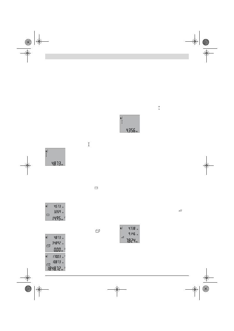
Slovensky |
95
Bosch Power Tools
2 609 140 773 | (4.12.12)
Výber vzťažnej roviny (pozri obrázok A)
Na uskutočnenie merania si môžete vyberať spomedzi troch
rozličných vzťažných rovín:
– zadnú hranu meracieho prístroja (napr. pri priložení mera-
cieho prístroja k stene),
– prednú hranu meracieho prístroja (napr. pri meraní od hra-
ny stola),
– stred závitu
14
(napr. pri meraniach so statívom).
Ak chcete zvoliť vzťažnú rovinu, stláčajte tlačidlo
6
dovtedy,
kým sa na displeji zobrazí požadovaná vzťažná rovina. Po kaž-
dom zapnutí meracieho prístroja je ako vzťažná rovina pred-
nastavená zadná hrana meracieho prístroja.
Osvetlenie displeja
Osvetlenie displeja sa aktivuje automaticky vždy so zreteľom
na osvetlenie okolia prístroja. Ak sa po zapnutí osvetlenia
displeja neuskutoční stlačenie niektorého tlačidla, osvetlenie
sa kvôli šetreniu batérií automaticky stlmí.
Meracie funkcie
Jednoduché meranie dĺžky (pozri obrázok B)
Na meranie dĺžky stláčajte tlačidlo
9
dovtedy, kým sa na disp-
leji objaví indikácia pre meranie dĺžky .
Ak chcete zapnúť laser a vykonať mera-
nie, stlačte každý raz jedenkrát krátko tla-
čidlo Meranie
2
.
Nameraná hodnota sa zobrazí v riadku
pre výsledok
b
.
V prípade viacnásobného merania dĺžky za sebou sa výsledky
posledných meraní zobrazia v riadkoch pre namerané hodno-
ty
a
.
Meranie plochy (pozri obrázok C)
Na meranie plochy stláčajte tlačidlo
3
dovtedy, kým sa na
displeji objaví indikácia pre meranie plochy
.
Potom postupne premerajte za sebou dĺžku a šírku ako pri me-
raní vzdialenosti. Laserový lúč zostáva medzi oboma merania-
mi zapnutý.
Po skončení druhého merania sa plocha
automaticky prepočíta a zobrazí sa na
displeji v riadku pre výsledok
b
. Jednotli-
vé namerané hodnoty sú zobrazené v
riadkoch pre namerané hodnoty
a
.
Meranie objemu (pozri obrázok D)
Na meranie objemu stláčajte tlačidlo
3
dovtedy, kým sa na
displeji objaví indikácia pre meranie objemu
.
Potom postupne premerajte za sebou dĺž-
ku, šírku a výšku ako pri meraní vzdiale-
nosti. Laserový lúč zostáva medzi týmito
troma meraniami zapnutý.
Po skončení tretieho merania sa objem
automaticky prepočíta a zobrazí sa na
displeji v riadku pre výsledok
b
. Jed-
notlivé namerané hodnoty sú zobrazené v
riadkoch pre namerané hodnoty
a
.
Hodnoty vyššie ako 999999 m
3
sa nadajú zobraziť, v takom
prípade sa na displeji zobrazí indikácia
„ERROR“
. Rozdeľte
objem, ktorý potrebujete odmerať, na jednotlivé merania,
ktorých hodnoty vypočítate osobitne a potom ich zhrniete
(spočítate) dohromady.
Trvalé meranie (pozri obrázok E)
Pri trvalom meraní sa môže merací prístroj relatívne pohybo-
vať k cieľu, pričom nameraná hodnota sa aktualizuje každých
0,5 sek. Môžete sa napríklad vzďaľovať od nejakej steny až do
požadovanej vzdialenosti, na prístroji sa dá v každom okami-
hu odčítať aktuálna vzdialenosť.
Na zapnutie trvalého merania stláčajte tlačidlo
9
dovtedy,
kým sa na displeji objaví indikácia pre trvalé meranie. Na
spustenie trvalého merania stlačte tlačidlo Meranie
2
.
Aktuálna nameraná hodnota sa zobrazí v
riadku pre výsledok
b
.
Stlačením tlačidla Meranie
2
trvalé mera-
nie ukončíte. Posledná nameraná hodno-
ta sa zobrazí v riadku pre výsledok
b
. No-
vé stlačenie tlačidla Meranie
2
spustí trva-
lé meranie znova.
Trvalé meranie sa po 5 minútach automaticky vypne. Posled-
ná nameraná hodnota sa zobrazí v riadku pre výsledok
b
.
Nepriame meranie výšky / Jednoduché meranie podľa Py-
tagorovej vety (pozri obrázok F)
Nepriame meranie výšky slúži na zisťovanie takých vzdiale-
ností, ktoré sa nedajú merať priamo, pretože laserový lúč by
bol prerušený prekážkou, alebo v takom prípade, ak nie je k
dispozícii žiadna taká cieľová plocha, ktorá by mohla poslúžiť
ako reflexná plocha. Korektné výsledky sa môžu dosiahnuť iba
v takom prípade, keď sa pri príslušnom meraní exaktne dodrží
požadovaný pravý uhol (podľa Pytagorovej vety).
Dávajte pritom pozor na to, aby sa vzťažný bod merania (nap-
ríklad zadná hrana meracieho prístroja) nachádzal pri všet-
kých jednotlivých meraniach v rámci jedného meracieho úko-
nu presne na tom istom mieste.
Laserový lúč zostáva medzi týmito jednotlivými meraniami za-
pnutý.
Stláčajte tlačidlo
3
dovtedy, kým sa na displeji zobrazí indiká-
cia pre jednoduché meranie podľa Pytagorovej vety
.
Odmerajte ako pri meraní dĺžky trasy
„1“
a
„2“
v uvedenom
poradí. Dávajte pozor na to, aby medzi trasou
„1“
a hľadanou
trasou
„X“
existoval pravý uhol.
Po skončení posledného merania sa vý-
sledok pre hľadanú trasu
„X“
zobrazí v
riadku pre výsledok
b
. Jednotlivé name-
rané hodnoty sú zobrazené v riadkoch pre
namerané hodnotyn
a
.
Vymazanie nameraných hodnôt
Krátkym stlačením tlačidla
4
môžete vo všetkých meracích
funkciách vymazať naposledy odmerané jednotlivé hodnoty.
Viacnásobným krátkym stlačením tohto tlačidla sa vymazáva-
jú jednotlivé namerané hodnoty v opačnom poradí.
OBJ_BUCH-1444-004.book Page 95 Tuesday, December 4, 2012 1:47 PM
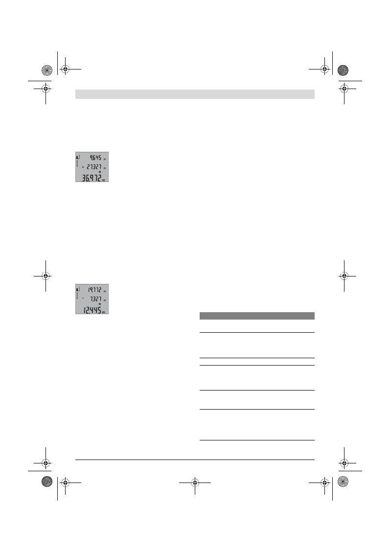
96
| Slovensky
2 609 140 773 | (4.12.12)
Bosch Power Tools
Sčítavanie nameraných hodnôt
Keď chcete namerané hodnoty sčítavať, vykonajte najprv jed-
no ľubovoľné meranie. Potom stlačte Tlačidlo plus
8
. Na disp-
leji sa na potvrdenie zobrazí
„+“
.
Keď chcete sčítavať objemy alebo plochy, stlačte po ukončení
prvého merania tlačidlo plus
8
. Na displeji sa na potvrdenie
zobrazí
„+“
v polohe naľavo od symbolu objemu/plochy.
Potom vykonajte druhé meranie.
Keď chcete zistiť (vyvolať na displej) sú-
čet oboch meraní, stlačte ešte jedenkrát
tlačidlo plus
8
. Výpočet sa zobrazí v riad-
koch pre namerané hodnoty
a
, súčet sa
zobrazí v riadku pre výsledok
b
.
Po vypočítaní súčtu sa môžu k tomuto výsledku pripočítavať
ďalšie namerané hodnoty alebo hodnoty zapísané v zozname
nameraných hodnôt, keď sa pred meraním vždy stlačí tlačidlo
Plus
8
.
Upozornenie k sčítavaniu:
– Ak sa napríklad spočítava dohromady nejaká hodnota dĺž-
ky a nejaká hodnota plochy, pri stlačení tlačidla Plus
8
sa
na displeji na chvíľu objaví indikácia
„ERROR“
. Potom
prejde merací prístroj do tej meracej funkcie, ktorá bola
aktivovaná naposledy.
– Pripočítava sa vždy výsledok jedného merania (napr. hod-
nota objemu), pri trvalých meraniach nameraná hodnota
indikovaná v riadku pre výsledok
b
. Sčítavanie jednotli-
vých nameraných hodnôt z riadkov pre namerané hodnoty
a
nie je možné.
Odčítavanie nameraných hodnôt
Ak chcete odpočítavať namerané hodno-
ty, stlačte tlačidlo Mínus
5
a na potvrde-
nie sa na displeji objaví indikácia
„–“
. Ďal-
ší postup je analogický ako pri „Sčítavanie
nameraných hodnôt“.
Pokyny na používanie
Všeobecné upozornenia
Prijímacia šošovka
12
a výstup laserového lúča
11
nesmú byť
počas merania zakryté.
Počas merania nesmiete merací prístroj pohybovať (s výnim-
kou funkcie Trvalé meranie). Prikladajte vždy preto merací
prístroj podľa možnosti na pevnú dorazovú alebo podkladovú
plochu.
Čo ovplyvňuje merací rozsah
Merací rozsah závisí od svetelných pomerov a reflexných
vlastností cieľovej plochy. Aby ste laserový lúč lepšie videli,
použite pri meraní vonku a pri silnom slnečnom žiarení okulia-
re na zviditeľnenie laserového lúča
19
(príslušenstvo) a lase-
rovú cieľovú tabuľku
20
(príslušenstvo), alebo cieľovú plochu
nejakým vhodným spôsobom zatieňte.
Čo ovplyvňuje výsledok merania
Na základe fyzikálnych efektov sa nedá vylúčiť, aby sa pri me-
raní na rozličných povrchových plochách neobjavili chyby
merania. Sem patria nasledovné:
– priehľadné povrchové plochy (napr. sklo, voda),
– zrkadliace povrchové plochy (napr. leštený kov, sklo),
– porózne povrchové plochy (napr. rôzne izolačné materiá-
ly),
– štrukturované povrchové plochy (napr. hrubá omietka,
prírodný kameň).
V prípade potreby použite na týchto povrchových plochách
laserovú cieľovú tabuľku
20
(príslušenstvo).
Chybné merania sa okrem toho môžu vyskytovať na šikmých
zameraných cieľových plochách.
Nameranú hodnotu môžu takisto ovplyvňovať vzduchové
vrstvy s rozlične vysokou teplotou alebo nepriamo prijímané
reflexie (odrazy) nameranej hodnoty.
Kontrola presnosti merania vzdialenosti
Presnosť merania vzdialenosti môžete prekontrolovať nasle-
dovne:
– Zvoľte trvalo nemennú meraciu trasu v dĺžke cca 1 až
10 m, ktorej dĺžku presne poznáte (napríklad šírku miest-
nosti, otvor dverí a pod.). Táto meracia trasa sa musí na-
chádzať vo vnútorných priestoroch, cieľová plocha mera-
nia musí byť hladká a musí mať dobrú odrazivosť.
– Odmerajte túto trasu (vzdialenosť) 10-krát za sebou.
Odchýlka jednotlivých meraní od strednej hodnoty smie byť
maximálne ±2 mm. Zaprotokolujte si tieto merania, aby ste
neskôr mohli presnosť meraní porovnávať.
Práca so statívom (Príslušenstvo)
Použitie statívu je nevyhnutné predovšetkým pri väčších
vzdialenostiach. Umiestnite merací prístroj závitom 1/4"
14
na rýchlupínaciu platničku statívu
18
alebo nejakého bežného
fotografického statívu. Aretačnou skrutkou ho dobre priskrut-
kujte na rýchloupínaciu platničku statívu.
Stláčaním tlačidla
6
nastavte príslušnú vzťažnú rovinu pre me-
ranie so statívom (vzťažná rovina závit).
Poruchy – príčiny a ich odstránenie
Príčina
Odstránenie
Výstraha nevhodnej teploty (f) bliká, meranie nie je
možné
Merací prístroj sa nachádza mimo
rámca prevádzkovej teploty od
– 10 °C do +50 °C (vo funkcii
trvalé meranie do +40 °C).
Počkajte, kým merací
prístroj dosiahne pre-
vádzkovú teplotu
Indikácia „ERROR“ na displeji
Sčítavanie/odčítavanie namera-
ných hodnôt s rozdielnymi merací-
mi jednotkami
Sčítavajte/odčítavajte
len namerané hodnoty s
rovnakými meracími jed-
notkami
Uhol medzi laserovým lúčom a
cieľom je príliš ostrý.
Zväčšite uhol medzi
laserovým lúčom a cieľ-
om
Cieľová plocha reflektuje príliš in-
tenzívne (napríklad zrkadlo) alebo
príliš slabo (napríklad čierna lát-
ka), prípadne vtedy, ak je okolité
svetlo príliš silné.
Použite cieľovú tabuľku
20
(príslušenstvo)
OBJ_BUCH-1444-004.book Page 96 Tuesday, December 4, 2012 1:47 PM
Magyar |
97
Bosch Power Tools
2 609 140 773 | (4.12.12)
Merací prístroj kontroluje korektné fungo-
vanie pri každom meraní. Keď sa zistí poru-
cha, na displeji bliká už len symbol, ktorý sa
nachádza vedľa. V takomto prípade, alebo
ak vyššie uvedené opatrenia nevedia od-
strániť poruchu, doručte merací prístroj
prostredníctvom svojho predajcu autorizovanému servisné-
mu stredisku Bosch.
Údržba a servis
Údržba a čistenie
Merací prístroj skladujte a transportujte v ochrannej taške,
ktorá sa dodáva spolu s meracím prístrojom.
Udržiavajte svoj merací prístroj vždy v čistote.
Neponárajte merací prístroj do vody ani do iných kvapalín.
Znečistenia utrite vlhkou mäkkou handričkou. Nepoužívajte
žiadne čistiace prostriedky ani rozpúšťadlá.
Predovšetkým prijímaciu šošovku
12
ošetrujte rovnako
starostlivo, ako treba ošetrovať napríklad okuliare alebo šo-
šovku fotoaparátu.
Ak by merací prístroj napriek starostlivej výrobe a kontrole
predsa len prestal niekedy fungovať, treba dať opravu vykonať
autorizovanej servisnej opravovni ručného elektrického nára-
dia Bosch. Merací prístroj sami nikdy neotvárajte.
Pri všetkých dopytoch a objednávkach náhradných súčiastok
uvádzajte bezpodmienečne 10-miestne vecné číslo uvedené
na typovom štítku výrobku.
V prípade potreby zasielajte merací prístroj do opravy v
ochrannej taške
17
.
Servisné stredisko a poradenstvo pri používaní
Servisné stredisko Vám odpovie na otázky týkajúce sa opravy
a údržby Vášho produktu ako aj náhradných súčiastok. Rozlo-
žené obrázky a informácie k náhradným súčiastkam nájdete aj
na web-stránke:
www.bosch-pt.com
Tím poradcov Bosch Vám s radosťou poskytne pomoc pri
otázkach týkajúcich sa našich produktov a ich príslušenstva.
Slovakia
Tel.: (02) 48 703 800
Fax: (02) 48 703 801
E-Mail: servis.naradia@sk.bosch.com
www.bosch.sk
Likvidácia
Výrobok, príslušenstvo a obal treba dať na recykláciu šetriacu
životné prostredie.
Neodhadzujte opotrebované meracie prístroje ani akumuláto-
ry/batérie do komunálneho odpadu!
Len pre krajiny EÚ:
Podľa Európskej smernice 2002/96/ES sa
musia už nepoužiteľné meracie prístroje a
podľa európskej smernice 2006/66/ES sa
musia poškodené alebo opotrebované aku-
mulátory/batérie zbierať separovane a tre-
ba ich dávať na recykláciu zodpovedajúcu
ochrane životného prostredia.
Zmeny vyhradené.
Magyar
Biztonsági előírások
A mérőműszerrel végzett munkák veszély-
mentes és biztonságos végrehajtásához
minden előírást gondosan végig kell olvas-
ni és be kell tartani. Sohase tegye felismer-
hetetlenné a mérőműszeren elhelyezett
figyelmeztető táblákat. KÉRJÜK GONDO-
SAN ŐRIZZE MEG EZEKET AZ ELŐÍRÁSOKAT.
Vigyázat – ha az itt leírtaktól eltérő kezelő vagy beállí-
tó berendezéseket használ, vagy más eljárásokat alkal-
maz, ez veszélyes sugárterheléshez vezethet.
Výstup laserového lúča
11
resp.
prijímacia šošovka
12
sú zarosené
(napríklad následkom rýchlej zme-
ny teploty).
Pomocou mäkkej han-
dričky vytrite výstup la-
serového lúča
11
resp.
prijímaciu šošovku
12
dosucha
Vypočítaná hodnota je väčšia ako
999999 m/m
2
/m
3
.
Výpočet rozdeľte na jed-
notlivé čiastkové kroky
Výsledok merania je nepravdepodobný
Cieľová plocha nereflektuje jedno-
značne (napríklad voda, sklo).
Zakryte cieľovú plochu
Výstup laserového lúča
11
resp.
prijímacia šošovka
12
sú prikryté.
Výstup laserového lúča
11
príjímaciu šošovku
12
uvoľnite
Nastavená nesprávna vzťažná rovi-
na
Vyberte takú vzťažnú ro-
vinu, ktorá sa hodí pre
dané meranie
Na dráhe laserového lúča je pre-
kážka
Laserový bod sa musí
celý nachádzať na cieľo-
vej ploche.
Indikácia zostáva nezmenená alebo merací prístroj rea-
guje na stlačenie tlačidla nečakane
Softvérová chyba
Vyberte batérie a po no-
vom vložení spustite me-
rací prístroj znova.
Príčina
Odstránenie
OBJ_BUCH-1444-004.book Page 97 Tuesday, December 4, 2012 1:47 PM
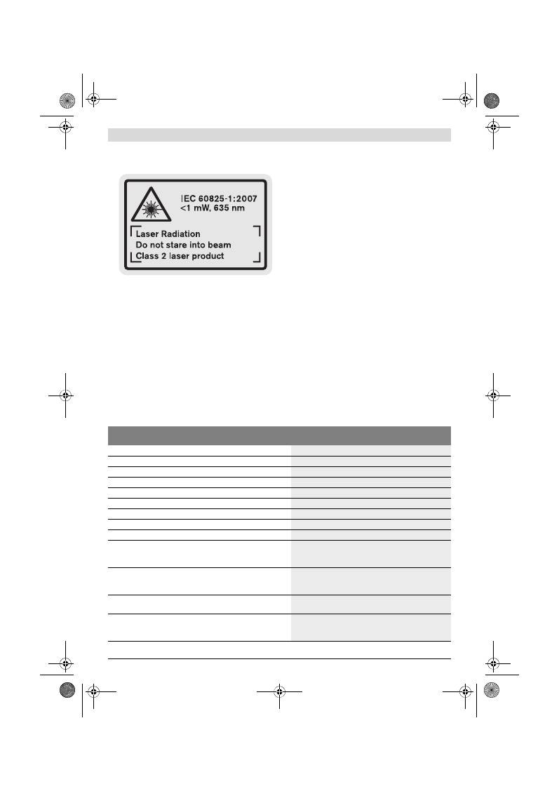
98
| Magyar
2 609 140 773 | (4.12.12)
Bosch Power Tools
A mérőműszer egy angol nyelvű figyelmeztető táblával
kerül szállításra (a képes oldalon a mérőműszer rajzán
a 15 számmal van jelölve).
Ragassza át az angol nyelvű figyelmeztető táblát az el-
ső üzembe helyezés előtt a készülékkel szállított meg-
felelő nyelvű öntapadó címkével.
Ne irányítsa a lézersugarat más személyekre vagy álla-
tokra és saját maga se nézzen bele a lézersugárba.
Ez a
mérőműszer az IEC 60825-1 szabványban megadottak-
nak megfelelő 2. lézerosztályú lézersugárzást bocsát ki.
Ezzel el lehet vakítani más személyeket.
Ne használja a lézerpontkereső szemüveget
védőszemüvegként.
A lézerpontkereső szemüveg a lézer-
sugár felismerésének megkönnyítésére szolgál, de nem
nyújt védelmet a lézersugárral szemben.
Ne használja a lézerpontkereső szemüveget napszem-
üvegként vagy a közlekedésben egyszerű szemüveg-
ként.
A lézerpontkereső szemüveg nem nyújt teljes védel-
met az ultraibolya sugárzással szemben és csökkenti a
színfelismerési képességet.
A mérőműszert csak szakképzett személyzet csak ere-
deti pótalkatrészek felhasználásával javíthatja.
Ez biz-
tosítja, hogy a mérőműszer biztonságos műszer maradjon.
Ne hagyja, hogy gyerekek a lézersugárral felszerelt
mérőműszert felügyelet nélkül használják.
Ezzel akarat-
lanul elvakíthatnak más személyeket.
Ne dolgozzon a mérőműszerrel olyan robbanás-
veszélyes környezetben, ahol éghető folyadékok, gá-
zok vagy porok vannak.
A mérőműszerben szikrák kelet-
kezhetnek, amelyek a port vagy a gőzöket meggyújthatják.
A termék és alkalmazási lehetőségei
leírása
Kérjük hajtsa ki a Kezelési Utasításnak a mérőműszer képét
tartalmazó kihajtható lapját, miközben a Kezelési Utasítást ol-
vassa.
Rendeltetésszerű használat
A mérőműszer távolságok, hosszúság és magasság mérésére
és felületek és térfogatok kiszámítására szolgál. A mérőmű-
szer mind beltéri, mind a szabadban végzett mérésekhez
használható.
Műszaki adatok
Digitális lézeres távolságmérő
GLM 50
Professional
Cikkszám
3 601 K72 2..
Mérési tartomány
0,05 –50 m
A)
Mérési pontosság (tipikusan)
±1,5 mm
B)
Legkisebb kijelezhető egység
1 mm
Üzemi hőmérséklet
–10 °C...+50 °C
C)
Tárolási hőmérséklet
–20 °C...+70 °C
A levegő megengedett legmagasabb nedvességtartalma, max.
90 %
Lézerosztály
2
Lézertípus
635 nm, <1 mW
Lézersugár átmérő (25 °C mellett) kb.
– 10 m távolságban
– 50 m távolságban
6 mm
35 mm
Automatikus kikapcsolás kb.
– Lézer
– Mérőműszer (mérés nélkül)
20 s
5 perc
Elemek
Akkumulátorcellák
2 x 1,5 V LR03 (AAA)
2 x 1,2 V HR03 (AAA)
Az elem élettartama kb.
– Egyedi mérések
– Tartós mérés
10000
D)
2,5 óra
D)
OBJ_BUCH-1444-004.book Page 98 Tuesday, December 4, 2012 1:47 PM
Magyar |
99
Bosch Power Tools
2 609 140 773 | (4.12.12)
Az ábrázolásra kerülő komponensek
Az ábrázolásra kerülő alkatrészek számozása a mérőműszer-
nek az ábrákat tartalmazó oldalon található ábráira vonatko-
zik.
1
Kijelző
2
Mérési billentyű
3
Felület-, térfogat- és közvetett magasságmérési billentyű
(Pythagoras)
4
Törlőgomb / BE-/KI-gomb **
5
Mínusz gomb
6
Vonatkoztatási sík kijelölő gomb
7
Tartóheveder rögzítő
8
Plusz gomb
9
Hosszmérési és tartós mérési billentyű
10
Az elemtartó fedele
11
Lézersugár kilépési pontja
12
Vevőlencse
13
Gyártási szám
14
1/4"-menet
15
Lézer figyelmeztető tábla
16
Az elemtartó fiók fedelének reteszelése
17
Védőtáska
18
Tartóállvány*
19
Lézerpont kereső szemüveg*
20
Lézer-céltábla*
* A képeken látható vagy a szövegben leírt tartozékok részben nem
tartoznak a standard szállítmányhoz.
** A kiterjesztett funkciók megjelenítéséhez tartsa benyomva a
gombot.
Kijelző elemek
a
Mérési érték sorok
b
Eredmény sor
c
Mérési funkciók
d
A lézer be van kapcsolva
e
Mérési vonatkoztató sík
f
Hőmérséklet figyelmeztetés
g
Akkumulátor figyelmeztetés
h
Hibakijelzés
„ERROR”
Összeszerelés
Elemek behelyezése/kicserélése
A mérőműszer üzemeltetéséhez alkáli-mangán-elemek vagy
akkumulátorok használatát javasoljuk.
1,2-V akkumulátorokkal kevesebb mérést lehet végrehajtani,
mint 1,5-V elemekkel.
A
10
elemfiók fedelének felnyitásához nyomja meg a
16
rete-
szelést és vegye le az elemfiók fedelét. Tegye be az elemeket,
illetve az akkumulátorokat. Az elemek, illetve akkumulátorok
behelyezésekor ügyeljen az elemfiókban található ábrának
megfelelő polaritásra.
Az elemek, illetve akkumulátorok behelyezésekor ügyeljen az
elemfiókban található ábrának megfelel helyes polaritásra.
Amikor a kijelzőn először megjelenik a
elem-szimbólum,
akkor még legalább 100 egyedi mérésre van lehetőség. A tar-
tós mérési funkció ekkor deaktiválva van.
Ha az elemszimbólum
villog, ki kell cserélni az elemeket, il-
letve az akkumulátorcellákat. A mérőműszerrel ekkor már
nem lehet több mérést végrehajtani.
Mindig valamennyi elemet, illetve akkumulátort egyszerre
cserélje ki. Csak egyazon gyártó cégtől származó és azonos
kapacitású elemeket vagy akkumulátorokat használjon.
Vegye ki az elemeket, illetve az akkumulátorokat a mé-
rőműszerből, ha azt hosszabb ideig nem használja.
Az
elemek és akkumulátorok egy hosszabb tárolás során kor-
rodálhatnak, vagy maguktól kimerülhetnek.
Súly az „EPTA-Procedure 01/2003” (2003/01 EPTA-eljárás) sze-
rint
0,14 kg
Méretek
53 x 114 x 30 mm
Védettségi osztály
IP 54 (por és fröccsenő víz ellen védett kivitel)
Digitális lézeres távolságmérő
GLM 50
Professional
A) A készülék hatótávolsága annál nagyobb, minél jobban visszaveri a felület a lézerfényt (szórva, nem tükrözve) és minél jobban kiválik a lézerfénypont
a környezetből (belső helyiségek, alkonyodás). Hátrányos feltételek mellett (például a szabadban erős napsugárzás mellett végrehajtott mérések ese-
tén) szükség lehet a célzőtábla alkalmazására.
B) Azoknál a méréseknél, amelyeknél a vonatkoztató sík a mérőműszer hátsó éle. Hátrányos körülmények, például erős napsugárzás vagy rossz vissza-
verő tulajdonságú felület esetén a maximális eltérés 50 m távolságban
±
10 mm. Előnyös körülmények esetén
±
0,05 mm/m eltérésre lehet számítani.
C) Tartós mérés üzemmódban a maximális megengedett üzemi hőmérséklet +40
°C
.
D) 1,2-V akkumulátorokkal kevesebb mérést lehet végrehajtani, mint 1,5-V elemekkel. Az elem megadott élettartama kijelző megvilágítás nélküli mé-
résekre vonatkozik.
Az ön mérőműszere a típustáblán található
13
gyártási számmal egyértelműen azonosítható.
Hosszmérés
Tartós mérés
Felületmérés
Térfogatmérés
Egyszerű Pitagorasz-mérés
OBJ_BUCH-1444-004.book Page 99 Tuesday, December 4, 2012 1:47 PM
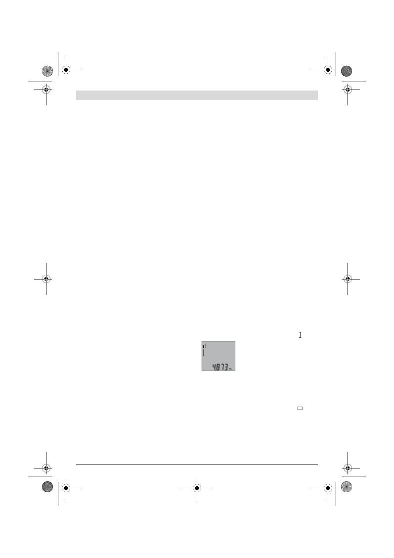
100
| Magyar
2 609 140 773 | (4.12.12)
Bosch Power Tools
Üzemeltetés
Üzembevétel
Sohase hagyja a bekapcsolt mérőműszert felügyelet
nélkül és használat után mindig kapcsolja ki a mérő-
műszert.
A lézersugár más személyeket elvakíthat.
Óvja meg a mérőműszert a nedvességtől és a közvetlen
napsugárzás behatásától.
Ne tegye ki a mérőműszert extrém hőmérsékleteknek
vagy hőmérsékletingadozásoknak.
Például ne hagyja
hosszabb ideig a mérőműszert egy autóban. Nagyobb
hőmérsékletingadozások után hagyja a mérőműszert tem-
perálódni, mielőtt azt ismét üzembe venné. Extrém hőmér-
sékletek vagy hőmérséklet ingadozások befolyásolhatják a
mérőműszer mérési pontosságát.
Ügyeljen arra, hogy a mérőműszer ne eshessen le és ne
legyen kitéve erősebb lökéseknek vagy ütéseknek.
Ha
a mérőműszert erős külső hatás érte, a munka folytatása
előtt ellenőrizze annak pontosságát (lásd „A távolságmérés
pontosságának ellenőrzése”, a 102. oldalon).
Be- és kikapcsolás
A mérőműszer
bekapcsolásához
a következő lehetőségek
állnak rendelkezésre:
– Nyomja meg a
4
Be-/Ki-gombot: A mérőműszer bekapcso-
lásra kerül és a hosszmérési funkcióban van. A lézer nem
kerül bekapcsolásra.
– Nyomja meg a
2
mérési gombot: A mérőműszer és a lézer
bekapcsolásra kerül. A mérőműszer a hosszmérési funkci-
óban van.
Sohase irányítsa a lézersugarat személyekre vagy álla-
tokra, és sohase nézzen bele közvetlenül, – még na-
gyobb távolságból sem – a lézersugárba.
A mérőműszer
kikapcsolásához
nyomja meg hosszabb időre
a
4
Be-/Kikapcsoló billentyűt.
Ha a mérőműszeren kb. 5 percig egyik billentyűt sem nyomják
meg, a mérőműszer az elemek kímélésére automatikusan ki-
kapcsol.
Mérési folyamat
A
2
billentyű megnyomásával végrehajtott bekapcsolás után a
készülék mindig a „Hosszmérés” funkcióra kapcsol. Más mé-
rési funkciókat a mindenkori funkcióbillentyűvel lehet beállí-
tani (lásd „Mérési funkciók”, a 100. oldalon).
A mérőműszer minden egyes bekapcsolása után a mérőmű-
szer hátsó éle van vonatkoztató síkként beállítva. A
6
vonat-
koztató sík billentyű megnyomásával a vonatkoztató síot meg
lehet változtatni (lásd „A vonatkoztató sík kijelölése”, a 100
oldalon).
Tegye fel a mérőműszert a kiválasztott vonatkozási síkjával a
mérés kívánt kezdőpontjára (például egy falra).
A lézersugár bekapcsolásához nyomja meg rövid időre a
2
mé-
rési billentyűt.
Sohase irányítsa a lézersugarat személyekre vagy álla-
tokra, és sohase nézzen bele közvetlenül, – még na-
gyobb távolságból sem – a lézersugárba.
Irányítsa a lézersugat a célfelületre. A mérés kiváltásához
nyomja meg ismét a
2
mérési billentyűt.
A tartós mérés funkció esetén a mérés a funkció bekapcsolá-
sakor azonnal megkezdődik.
A mérési eredmény tipikusan 0,5 másodpercen belül és leg-
később 4 másodperc elteltével jelenik meg. A mérés időtarta-
ma a távolságtól, a megvilágítási viszonyoktól és a célfelület
visszaverési tulajdonságaitól függ. A mérés befejezése után a
lézer automatikusan kikapcsolódik.
Ha a lézersugár irányának beállítása után kb. 20 másodpercig
nem történik mérés, a lézersugár az elemek kímélésére auto-
matikusan kikapcsolódik.
A vonatkoztató sík kijelölése (lásd az „A” ábrát)
A méréshez három különböző vonatkoztató sík között lehet
választani:
– a mérőműszer hátsó éle (például ha egy falhoz tartja a be-
rendezést),
– a mérőműszer első éle (például egy asztal élétől kiinduló
méréshez),
– a
14
menet középpontja (például a háromlábú műszeráll-
vány alkalmazásával végzett méréshez),
A vonatkoztatási sík kijelöléséhez nyomja meg annyiszor egy-
más után a
6
gombot, amíg a kijelzőn megjelenik a kívánt vo-
natkoztatási sík. A mérőműszer minden egyes bekapcsolása
után a mérőműszer hátsó éle van vonatkoztató síkként beállít-
va.
A kijelző megvilágítása
A kijelző megvilágítása a környezeti fénytől függően automati-
kusan kerül bekapcsolásra. Ha a kijelző megvilágításának be-
kapcsolása után nem nyom meg egyetlen gombot sem, a kijel-
ző megvilágítása az elemek kímélésére letompításra kerül.
Mérési funkciók
Egyszerű hosszmérés (lásd a „B” ábrát)
A hosszméréshez nyomja meg annyiszor egymás után a
9
gombot, hogy a kijelzőn megjelenjen a hosszmérés jele.
A lézer bekapcsolásához nyomja be egy-
szer röviden, majd a méréshez nyomja be
még egyszer röviden a
2
mérési gombot.
A mérési eredmény az
b
eredmény sor-
ban kerül kijelzésre.
Több, egymás után végrehajtott hosszmérés esetén az utolsó
mérések eredményei a
a
mérési érték sorokban kerülnek ki-
jelzésre.
Felületmérés (lásd a „C” ábrát)
A felületméréshez nyomja meg annyiszor egymás után a
3
gombot, amíg a kijelzőn megjelenik a felületmérés
jele.
Ezután a hosszméréshez hasonlóan egymás után mérje meg a
mérésre kerülő felület hosszúságát és szélességét. A két mé-
rés között a lézersugár bekapcsolt állapotban marad.
OBJ_BUCH-1444-004.book Page 100 Tuesday, December 4, 2012 1:47 PM
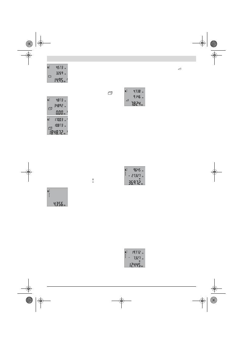
Magyar |
101
Bosch Power Tools
2 609 140 773 | (4.12.12)
A második mérés befejezése után a be-
rendezés automatikusan kiszámítja és az
b
eredmény sorban kijelzi a felületet. Az
egyedi mérési értékek a
a
mérési érték so-
rokban találhatók.
Térfogatmérés (lásd a „D” ábrát)
A térfogatméréshez nyomja meg annyiszor egymás után a
3
gombot, amíg a kijelzőn megjelenik a térfogatmérés
jele.
Ezután a hosszméréshez hasonlóan egy-
más után mérje meg a mérésre kerülő tér-
fogat hosszúságát, szélességét és
magasságát. A három mérés között a
lézersugár bekapcsolt állapotban marad.
A harmadik mérés befejezése után a be-
rendezés automatikusan kiszámítja és az
b
eredmény sorban kijelzi a térfogatot. Az
egyedi mérési értékek a
a
mérési érték so-
rokban találhatók.
A 999999 m
3
meghaladó értékeket a berendezés nem tudja
kijelezni, a kijelzőn ekkor megjelenik az
„ERROR”
(HIBA) ki-
jelzés. Ossza fel a mérésre kerülő térfogatot több részre, szá-
mítsa ki külön-külön ezek értékét, majd adja össze azokat.
Folyamatos mérés (lásd az „E” ábrát)
A folyamatos mérés alatt a mérőműszert a célhoz viszonyítva
el szabad mozgatni, a készülék a mért értéket kb. félmásod-
percenként aktualizálja. A felhasználó például eltávolódhat
egy faltól, amíg el nem éri a kívánt távolságot; az aktuális távol-
ság a készüléken mindig leolvasható.
Tartós mérésekhez tartsa benyomva a
9
gombot, amíg a kijel-
zőn meg nem jelenik a tartós mérések kijelzése. A tartós
mérés elindításához nyomja meg a
2
mérési billentyűt.
Az aktuális mérési eredmény az
b
ered-
mény sorban kerül kijelzésre.
A tartós mérést a
2
mérési billentyű meg-
nyomásával lehet befejezni. Az utolsó mé-
rési eredmény az
b
eredmény sorban ke-
rül kijelzésre. A tartós mérés ismételt elin-
dításához nyomja meg ismét a
2
mérési gombot.
A tartós mérés 5 perc elteltével automatikusan kikapcsolódik.
Az utolsó mérési eredmény az
b
eredmény sorban továbbra is
kijelzésre kerül.
Közvetett magasságmérés / Egyszerű Pitagorasz-mérés
(lásd az „F” ábrát)
A közvetett magasságmérés olyan szakaszok hosszának meg-
határozására szolgál, amelyeket közvetlenül nem lehet meg-
mérni, mert vagy valami akadály van a szakasz két vége kö-
zött, amely megszakítaná a lézersugarat, vagy nem áll rendel-
kezésre megfelelő fényvisszaverő felület. Helyes eredménye-
ket csak akkor lehet elérni, ha pontosan betartja a mindenkori
méréshez szükséges derékszöget (Pitagorasz-tétel).
Ügyeljen arra, hogy a mérés vonatkozási pontja (például a mé-
rőműszer hátsó éle) egy mérési eljáráson belül minden egyes
mérésnél pontosan ugyanazon a helyen maradjon.
A két külön mérés között a lézersugár bekapcsolt állapotban
marad.
Nyomja meg annyiszor egymás után a
3
gombot, amíg a kijel-
zőn megjelenik az egyszerű Pitagorasz-mérés
jele.
Mérje meg – egy hosszméréshez hasonlóan – az
„1”
és
„2”
szakaszt, pontosan ebben a sorrendben. Ügyeljen arra, hogy
az
„1”
szakasz és a keresett
„X”
szakasz pontosan derékszö-
get zárjon be egymással.
Az utolsó mérés befejezése után a kere-
sett szakasz
„X”
hossza az
b
eredmény
sorban kerül kijelzésre. Az egyedi mérési
értékek a
a
mérési érték sorokban találha-
tók.
A mérési eredmények törlése
A
4
billentyű rövid megnyomásával valamennyi mérési
funkciónál a legutoljára mért egyedi mérési eredményt lehet
kitörölni. A törlő billentyű többszöri egymás utáni rövid
megnyomásával az egyedi mért értékek a méréshez viszonyít-
va fordított sorrendben törlésre kerülnek.
A mérési értékek összeadása
A mérési eredmények összeadásához először hajtson végre
egy tetszőleges mérést. Ezután nyomja meg a
8
plusz gombot.
A kijelzőn ekkor visszaigazolásként megjelenik a
„+”
kijelzés.
Térfogatok vagy felületek összeadásához az első mérési eljá-
rás befejezése után nyomja meg a
8
plusz gombot. A kijelzőn
ekkor visszaigazolásként megjelenik a Térfogat-/ Felület jelé-
től balra a
„+”
kijelzés.
Ekkor hajtsa végre a második mérést.
A két mérés összegének lekérdezéséhez
nyomja meg még egyszer a
8
plusz gom-
bot. A számítás a
a
mérési érték sorok-
ban, az összeg a
b
eredmény sorban kerül
kijelzésre.
Az összeg kiszámítása után ehhez az eredményhez további
mérési értékeket lehet hozzáadni, ha a mérés előtt mindig
megnyomja a
8
plusz gombot.
Összeadási tájékoztató:
– Hosszúság-, felület- és térfogatértékeket nem lehet vegye-
sen összeadni. Ha például egy hosszúság- és egy felületér-
téket akar összeadni, akkor a
8
plust gomb megnyomása-
kor a kijelzőn rövid időre megjelenik az
„ERROR”
(HIBA)
kijelzés. A mérőműszer ezután átkapcsol a legutoljára aktív
mérési funkcióra.
– Egyszerre mindig egy mérés eredménye (például egy térfo-
gatérték) kerül hozzáadásra, tartós mérés esetén az
b
eredmény sorban kijelzett mérési eredmény. A
a
mérési
érték sorokból nem lehet egyedi mérési eredményeket ki-
venni és hozzáadni.
Mért értékek levonása a memória tartalmából
A mérési eredmények kivonásához nyom-
ja meg az
5
mínusz gomb, ennek nyug-
tázására a kijelzőn megjelenik a
„–”
jel. A
további eljárás hasonló a „A mérési érté-
kek összeadása”-ban leírtakhoz.
OBJ_BUCH-1444-004.book Page 101 Tuesday, December 4, 2012 1:47 PM
102
| Magyar
2 609 140 773 | (4.12.12)
Bosch Power Tools
Munkavégzési tanácsok
Általános tájékoztató
A
12
vevőlencsét és a lézersugár
11
kimeneti pontját mérés
közben nem szabad letakarni.
A mérőműszert mérés közben nem szabad mozgatni (kivéve a
tartós mérési funkciót). Ezért a mérőműszert lehetőleg egy
szilárd ütköző vagy felfekvő felületre helyezze.
Befolyások a mérési tartományra
A mérési tartomány a megvilágítási viszonyoktól és a célfelü-
let visszaverési tulajdonságaitól függ. A szabadban és erős
napsugárzás mellett végzett munkákhoz a lézerpont meg-
találásának megkönnyítésére használja a
19
lézerpont kereső
szemüveget (külön tartozék) és a
20
lézer-céltáblát (külön
tartozék), illetve vessen valamivel árnyékot a célfelületre.
Befolyások a mérési eredményre
Fizikai behatások következtében nem lehet kizárni, hogy a kü-
lönböző felületeken végzett mérések során hibás ered-
mények is fellépjenek. Ezek:
– átlátszó felületek (pl. üveg, víz),
– tükröző felületek (pl. fényezett fém, üveg),
– porózus felületek (pl. rezgéscsillapító vagy szigetelő anya-
gok),
– strukturált felületek (pl. nyersvakolat, terméskő).
Szükség esetén ezeken a felületeken használja a
20
lézer-cél-
táblát (külön tartozék).
Ezen kívül a ferdén beirányozott célfelületek is hibás eredmé-
nyekhez vezethetnek.
A mért értéket különböző hőmérsékletű levegőrétegek, vagy a
vevőhöz közvetett úton eljutó visszavert sugarak is meg-
hamisíthatják.
A távolságmérés pontosságának ellenőrzése
A távolságmérés pontosságát a következőképpen lehet ellen-
őrizni:
– Válasszon ki egy megváltoztathatatlan, kb 1 –10 m hos-
szúságú mérési vonalat, amelynek hosszúsága pontosan
ismert (pl. egy helyiség szélessége, egy ajtónyílás stb.). A
mérési szakasznak belső térben kell lennie a mérési célfe-
lületnek simának kell lennie és jó visszaverő tulajdonságok-
kal kell rendelkeznie.
– Mérje meg 10-szer egymás után ennek a mérési szakasz-
nak a hosszát.
Az egyedi méréseknek a középértéktől való eltérése legfel-
jebb ±2 mm lehet. Készítsen a mérésről jegyzőkönyvet, hogy
a készülék pontosságát egy későbbi időpontban össze tudja
hasonlítani a pillanatnyi pontossággal.
Munkavégzés a háromlábú műszerállvánnyal (külön tarto-
zék)
Egy háromlábú műszerállványra különösen nagyobb távolsá-
gok esetén van szükség. Tegye fel a mérőműszert a
14
1/4"-
menettel a
18
háromlábú műszerállvány gyorsváltólemezére
vagy egy a kereskedelemben kapható fényképező állványra. A
gyorsváltólap csavarjával rögzítse szorosan a berendezést.
Állítsa be a
6
billentyű megnyomásával a háromlábú műszer-
állvány használatával végzett mérésekhez szükséges vonat-
koztató síkot (vonatkoztató sík = a menet).
Hiba – Okok és elhárításuk
A mérőműszer minden egyes mérés során
sajátmaga felügyel a helyes működésre. Egy
hiba észlelésekor a kijelzőn csak az itt látha-
tó szimbólum villog. Ebben az esetben,
vagy ha a fent leírt hibaelhárítási eljárások
nem vezetnek eredményre, küldje el a
mérőműszert a kereskedőn keresztül a Bosch-vevőszol-
gálatnak.
A hiba oka
Elhárítás módja
A (f) hőmérséklet figyelmeztető villog, mérés nem lehet-
séges
A mérőműszer hőmérséklete a
megengedett – 10 °C és +50 °C
(a tartós mérés üzemmódban
+40 °C) közötti üzemi hőmérsék-
let tartományon kívül van.
Várja meg, amíg a mérő-
műszer eléri az üzemi
hőmérsékletet
„ERROR” kijelzés a kijelzőn
Különböző mértékegységű mért
értékek hozzáadása/kivonása
Csak azonos mérté-
kegységben megadott
mérési eredményeket
szabad összeadni, illet-
ve kivonni
A lézersugár és a célfelület közötti
szög túl kicsi.
Növelje meg a lézersugár
és a célfelület közötti
szöget
A célfelület túl erősen (például tü-
kör), illetve túl gyengén (például
fekete anyag) veri vissza a lézer-
sugarat, vagy túl erős a környezeti
megvilágítás.
Használja a
20
lézer-cél-
táblát (tartozék)
A
11
lézersugárzás kilépési pont,
illetve a
12
vevőlencse (például a
gyors hőmérsékletváltozás miatt)
bepárásodott.
Egy puha kendővel töröl-
je szárazra a lézersugár
11
kilépési pontját, illet-
ve a
12
vevő lencsét
A kiszámított érték nagyobb, mint
999999 m/m
2
/m
3
.
Ossza fel közbenső lépé-
sekre a számítást
A mérési eredmény nem plauzibilis
A célfelület (például vízfelület,
üveg) nem veri vissza egyértelmű-
en a lézersugarat.
Takarja le a célfelületet
A lézersugár
11
kilépési pontját, il-
letve a
12
vevő lencsét valami leta-
karja.
Tartsa szabadon a lézer-
sugár
11
kilépési pont-
ját, illetve a
12
vevő len-
csét
Hibás vonatkoztató sík van beállít-
va
Állítson be a méréshez il-
lő vonatkoztató síkot
Akadály a lézersugár útjában
A teljes lézerpontnak a
célfelületen kell feküd-
nie.
A kijelzés változatlan marad, vagy a mérőműszer váratla-
nul reagál a gombnyomásra
Szoftverhiba
Vegye ki az elemeket,
majd azok visszahelye-
zése után ismét indítsa
el a mérőműszert.
OBJ_BUCH-1444-004.book Page 102 Tuesday, December 4, 2012 1:47 PM
Русский |
103
Bosch Power Tools
2 609 140 773 | (4.12.12)
Karbantartás és szerviz
Karbantartás és tisztítás
A mérőműszert csak az azzal együtt szállított védőtáskában
tárolja és szállítsa.
Tartsa mindig tisztán a mérőműszert.
Ne merítse vízbe vagy más folyadékokba a mérőszerszámot.
A szennyeződéseket egy nedves, puha kendővel törölje le. Ne
használjon tisztító- vagy oldószereket.
Mindenekelőtt a
12
vevő lencsét ugyanolyan gondosan ápol-
ja, mint a szemüvegét, vagy a fényképezőgépe lencséjét.
Ha a mérőműszer a gondos gyártási és ellenőrzési eljárás elle-
nére egyszer mégis meghibásodna, akkor a javítással csak
Bosch elektromos kéziszerszám-műhely ügyfélszolgálatát
szabad megbízni. Ne nyissa fel saját maga a mérőműszert.
Ha kérdései vannak, vagy pótalkatrészeket akar megrendelni,
okvetlenül adja meg a mérőműszer típustábláján található
10-jegyű rendelési számot.
Ha javításra van szükség, a
17
védőtáskába csomagolva küld-
je be a mérőműszert.
Vevőszolgálat és használati tanácsadás
A Vevőszolgálat választ ad a termékének javításával és kar-
bantartásával, valamint a pótalkatrészekkel kapcsolatos kér-
déseire. A tartalékalkatrészekkel kapcsolatos robbantott áb-
rák és egyéb információk a címen találhatók:
www.bosch-pt.com
A Bosch Használati Tanácsadó Team szívesen segít, ha termé-
keinkkel és azok tartozékaival kapcsolatos kérdései vannak.
Magyarország
Robert Bosch Kft.
1103 Budapest
Gyömrői út. 120.
Tel.: (061) 431-3835
Fax: (061) 431-3888
Eltávolítás
A mérőműszereket, a tartozékokat és a csomagolást a
környezetvédelmi szempontoknak megfelelően kell újrafel-
használásra előkészíteni.
Ne dobja ki a mérőműszereket és az akkumulátorokat/ eleme-
ket a háztartási szemétbe!
Csak az EU-tagországok számára:
Az elhasznált mérőműszerekre vonatkozó
2002/96/EK európai irányelvnek és az el-
romlott vagy elhasznált akkumulátorokra/
elemekre vonatkozó 2006/66/EK európai
irányelvnek megfelelően a már nem hasz-
nálható akkumulátorokat/elemeket külön
össze kell gyűjteni és a környezetvédelmi szempontoknak
megfelelően kell újrafelhasználásra leadni.
A változtatások joga fenntartva.
Русский
Указания по безопасности
Для обеспечения безопасной и надеж-
ной работы с измерительным инстру-
ментом должны быть прочитаны и со-
блюдаться все инструкции. Никогда не
доводите предупредительные таблички
на измерительном инструменте до со-
стояния неузнаваемости. ХОРОШО СОХРАНИТЕ ЭТУ
ИНСТРУКЦИЮ.
Внимание – использование других не упомянутых
здесь элементов управления и регулирования или
других методов эксплуатации может подвергнуть
Вас опасному для здоровья излучению.
Настоящий измерительный инструмент поставляет-
ся с предупредительной табличкой на английском
языке (на рис. инструмента обозначена номером
15).
Перед первым запуском в эксплуатацию заклейте
английский текст предупредительной таблички на-
клейкой на Вашем родном языке, которая входит в
объем поставки.
Не направляйте лазерный луч на людей или живот-
ных и не смотрите сами в лазерный луч.
Настоящий
измерительный инструмент создает лазерное излуче-
ние класса 2 согласно IEC 60825-1. Этим излучением
Вы можете непреднамеренно ослепить людей.
Не применяйте лазерные очки в качестве защитных
очков.
Лазерные очки служат для лучшего распознава-
ния лазерного луча, однако они не защищают от лазер-
ного излучения.
Не применяйте лазерные очки в качестве солнеч-
ных очков или в уличном движении.
Лазерные очки
не дают полной защиты от ультрафиолетового излуче-
ния и ухудшают восприятие красок.
Ремонт Вашего измерительного инструмента пору-
чайте только квалифицированному персоналу, ис-
пользуя только оригинальные запасные части.
Этим
обеспечивается безопасность измерительного ин-
струмента.
OBJ_BUCH-1444-004.book Page 103 Tuesday, December 4, 2012 1:47 PM
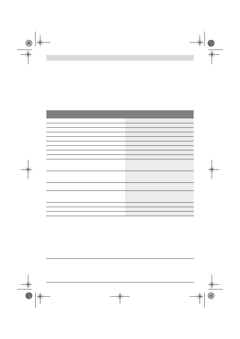
104
| Русский
2 609 140 773 | (4.12.12)
Bosch Power Tools
Не разрешайте детям пользоваться лазерным изме-
рительным инструментом без надзора.
Они могут не-
умышленно ослепить людей.
Не работайте с измерительным инструментом во
взрывоопасной среде, поблизости от горючих жид-
костей, газов и пыли.
В измерительном инструменте
могут образоваться искры, от которых может вос-
пламениться пыль или пары.
Описание продукта и услуг
Пожалуйста, откройте раскладную страницу с иллюстра-
циями инструмента и оставляйте ее открытой, пока Вы из-
учаете руководство по эксплуатации.
Применение по назначению
Измерительный инструмент предназначен для измерения
расстояний, длин, высот, удалений и расчетов площадей и
объемов. Измерительный инструмент подходит для рабо-
ты внутри помещений и на открытом воздухе.
Технические данные
Цифровой лазерный дальномер
GLM 50
Professional
Товарный №
3 601 K72 2..
Диапазон измерений
0,05 –50 м
A)
Точность измерения (типичная)
±1,5 мм
B)
Наименьшее отображаемое значение
1 мм
Рабочая температура
–10 °C...+50 °C
C)
Температура хранения
–20 °C...+70 °C
Относительная влажность воздуха не более
90 %
Класс лазера
2
Тип лазера
635 нм, <1 мВт
Диаметр лазерного луча (при 25 °C) ок.
– на расстоянии 10 м
– на расстоянии 50 м
6 мм
35 мм
Автоматическое отключение прибл. через
– лазер
– измерительный инструмент (без измерения)
20 с
5 мин
Батарейки
Аккумуляторные элементы
2 x 1,5 В LR03 (AAA)
2 x 1,2 В HR03 (AAA)
Срок службы батарей ок.
– Единичные измерения
– Продолжительное измерение
10000
D)
2,5 ч
D)
Вес согласно EPTA-Procedure 01/2003
0,14 кг
Размеры
53 x 114 x 30 мм
Степень защиты
IP 54 (защита от пыли и брызг воды)
A) Диапазон измерения тем больше, чем лучше лазерный луч отражается от поверхности цели (рассеивающее, не зеркальное отражение) и
чем ярче лазерная точка видна на фоне освещения окружающей среды (внутренние помещения, сумерки). При неблагопрятных условиях
(напр., работа на улице при сильном солнечном излучении) может понадобиться применение визирной марки.
B) При измерениях от заднего края измерительного инструмента. При неблагоприятных условиях, напр., сильное солнце или поверхность с
плохой отражательной способностью, максимальное отклонение составляет
±
10 мм на 50 м. При благоприятных условиях можно исходить
из
±
0,05 мм/м.
C) В режиме продолжительного измерения макс. рабочая температура составляет +40
°C
.
D) С аккумуляторными элементами на 1,2 В возможно меньше измерений, чем с батарейками на 1,5 В. Длительность работы батареек указана
для измерений без подсветки дисплея.
Однозначная идентификация Вашего измерительного инструмента возможна по серийному номеру
13
на заводской табличке.
OBJ_BUCH-1444-004.book Page 104 Tuesday, December 4, 2012 1:47 PM
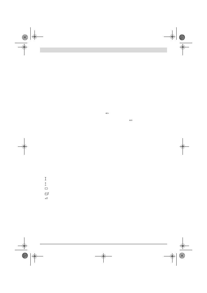
Русский |
105
Bosch Power Tools
2 609 140 773 | (4.12.12)
Изображенные составные части
Нумерация представленных составных частей выполнена
по изображению измерительного инструмента на страни-
це с иллюстрациями.
1
Дисплей
2
Кнопка измерения
3
Кнопка измерения площади, объема и непрямого из-
мерения высоты (теорема Пифагора)
4
Кнопка удаления / выключатель **
5
Кнопка «минус»
6
Кнопка выбора плоскости отсчета
7
Крепление для ремешка для переноса
8
Кнопка «плюс»
9
Кнопка измерения длины и продолжительного изме-
рения
10
Крышка батарейного отсека
11
Выход лазерного луча
12
Приёмная линза
13
Серийный номер
14
Резьба 1/4"
15
Предупредительная табличка лазерного излучения
16
Фиксатор крышки батарейного отсека
17
Защитный чехол
18
Штатив*
19
Очки для работы с лазерным инструментом*
20
Визирная марка*
* Изображенные или описанные принадлежности не входят в
стандартный комплект поставки.
** Для вызова дополнительных функций держите кнопку нажа-
той.
Элементы индикации
a
Измеренные значения
b
Результат
c
Режимы измерения
d
Лазер включен
e
Плоскость отсчета при измерении
f
Индикатор выхода за пределы допустимого темпера-
турного диапазона
g
Предупреждение о разрядке батареек
h
Индикатор ошибки
«ERROR»
Сборка
Установка/замена батареек
В измерительном инструменте рекомендуется использо-
вать щелочно-марганцевые батарейки или аккумулятор-
ные батареи.
С аккумуляторными батареями на 1,2 В возможно мень-
ше измерений, чем с батарейками на 1,5 В.
Чтобы открыть крышку батарейного отсека
10
, нажмите
фиксатор
16
и снимите крышку батарейного отсека.
Вставьте батарейки или аккумуляторные батареи. Следи-
те за правильной полярностью в соответствии с изображе-
нием на внутренней стороне крышки батарейного отсека.
При установке батареек/аккумуляторных батарей следите
за правильной направленностью полюсов в соответствии
с изображением внутри батарейного отсека.
После первого появления на дисплее символа батареек
возможно еще мин. 100 измерений. Функция продол-
жительного измерения отключена.
Если символ батареек
мигает, Вы должны заменить ба-
тарейки/аккумуляторные элементы. Продолжение изме-
рений более невозможно.
Всегда заменяйте все батарейки/аккумуляторные бата-
реи одновременно. Используйте только
батарейки/аккумуляторные батареи одного производите-
ля и с одинаковой емкостью.
Вынимайте батарейки/аккумуляторные батареи из
измерительного инструмента, если Вы длительное
время не будете его использовать.
При длительном
хранении возможна коррозия или саморазрядка бата-
реек/аккумуляторных батарей.
Работа с инструментом
Эксплуатация
Не оставляйте без присмотра включенный измери-
тельный инструмент и выключайте его после ис-
пользования.
Другие лица могут быть ослеплены
лазерным лучом.
Защищайте измерительный инструмент от влаги и
прямых солнечных лучей.
Не подвергайте измерительный инструмент воздей-
ствию экстремальных температур и температурных
перепадов.
В частности, не оставляйте его на длитель-
ное время в машине. При больших перепадах темпера-
туры сначала дайте измерительному инструменту ста-
билизировать свою температуру, прежде чем начинать
работать с ним. Экстремальные температуры и тем-
пературные перепады могут отрицательно влиять на
точность измерительного инструмента.
Избегайте сильных толчков и падений измеритель-
ного инструмента.
После сильных внешних воздейст-
вий на измерительный инструмент рекомендуется про-
верить его точность, прежде чем продолжать работать
с инструментом (см. «Проверка точности измерения
расстояния», стр. 108).
Измерение длины
Продолжительные измерения
Измерение площади
Измерение объема
Простое измерение по теореме Пифагора
OBJ_BUCH-1444-004.book Page 105 Tuesday, December 4, 2012 1:47 PM

106
| Русский
2 609 140 773 | (4.12.12)
Bosch Power Tools
Включение/выключение
Для
включения
измерительного инструмента Вы можете:
– Нажать кнопку включателя
4
: Измерительный инстру-
мент включается и находится в режиме измерения дли-
ны. Лазер при этом не включается.
– Нажмите кнопку измерения
2
: измерительный инстру-
мент и лазер включаются. Измерительный инструмент
находится в режиме измерения длины.
Не направляйте лазерный луч на людей или живот-
ных и не смотрите сами в лазерный луч, в том числе
и с большого расстояния.
Для
выключения
измерительного инструмента нажмите
кнопку выключения
4
и держите ее нажатой продолжи-
тельное время.
Если в течение прибл. 5 мин. на измерительном инстру-
менте не будет нажиматься никаких кнопок, измеритель-
ный инструмент с целью экономии батарей автоматически
выключается.
Измерение
После включения нажатием кнопки измерения
2
измери-
тельный инструмент всегда находится в режиме измере-
ния длины. Другие режимы измерения Вы можете настро-
ить нажатием кнопки соответствующего режима (см. «Ре-
жимы измерений», стр. 106).
В качестве плоскости отсчета для измерения после вклю-
чения задана задняя кромка инструмента. Нажатием на
кнопку плоскость отсчета
6
Вы можете изменить плос-
кость отсчета (см. «Выбор плоскости отсчета», стр. 106).
Положите измерительный инструмент выбранной плоско-
стью отсчета на нужную начальную точку измерения (на-
пример, на стену).
Для включения лазерного луча коротко нажмите на кноп-
ку измерения
2
.
Не направляйте лазерный луч на людей или живот-
ных и не смотрите сами в лазерный луч, в том числе
и с большого расстояния.
Наведите лазерный луч на цель. Для включения измере-
ния повторно коротко нажмите на кнопку измерения
2
.
В режиме продолжительных измерений измерение начи-
нается сразу же после включения режима.
Как правило, результат измерения появляется на протя-
жении 0,5 с, максимум через 4 с. Продолжительность из-
мерения зависит от расстояния, освещения и отражения
от целевой поверхности. После окончания измерения ла-
зерный луч автоматически отключается.
Если прибл. через 20 с после наведения не выполняется
никаких измерений, лазерный луч с целью экономии бата-
рей автоматически выключается.
Выбор плоскости отсчета (см. рис. А)
При измерении Вы можете выбрать одну из трех плоско-
стей отсчета:
– задний край измерительного инструмента (напр., при
прикладывании к стене),
– передний край измерительного инструмента (напр.,
при измерениях от края стола),
– центр резьбы
14
(напр., для измерений со штативом).
Для изменения плоскости отсчета нажимайте кнопку
6
до
тех пор, пока на дисплее не отобразится нужная плоскость
отсчета. Каждый раз после включения измерительного
инструмента в качестве плоскости отсчета задан задний
край инструмента.
Подсветка дисплея
Подсветка дисплея активируется автоматически в зависи-
мости от окружающего освещения. Если после включения
подсветки дисплея не будет нажата ни одна кнопка, с це-
лью экономии батареек подсветка дисплея приглушается.
Режимы измерений
Простое измерение длины (см. рис. В)
Для измерения длины нажимайте кнопку
9
до тех пор, по-
ка на дисплее не появится индикатор измерения длины .
Для включения лазера и проведения
измерений нажмите коротко один раз
на кнопку измерения
2
.
Измеренное значение появляется в
строке результата
b
.
При выполнении нескольких продолжительных измере-
ний друг за другом результаты последних измерений ото-
бражаются в строках измеренных значений
a
.
Измерение площади (см. рис. С)
Для измерения площади нажимайте кнопку
3
до тех пор,
пока на дисплее не появится индикатор измерения площа-
ди .
Измерьте длину и ширину друг за другом как при измере-
нии длин. Между обоими измерениями лазерный луч оста-
ется включенным.
По окончании второго измерения зна-
чение площади автоматически
рассчитывается и высвечивается в
строке результата
b
. Отдельные изме-
ренные значения отображаются в стро-
ках измеренных значений
a
.
Измерение объема (см. рис. D)
Для измерения объема нажимайте кнопку
3
до тех пор, по-
ка на дисплее не появится индикатор измерения объема
.
После этого измерьте длину, ширину и
высоту друг за другом как при измере-
нии длин. Между тремя измерениями
лазерный луч остается включенным.
По окончании третьего измерения объ-
ем автоматически рассчитывается и
высвечивается в строке результата
b
.
Отдельные измеренные значения ото-
бражаются в строках измеренных зна-
чений
a
.
Значения, превышающие 999999 м
3
, не могут отобра-
жаться и на дисплее высвечивается
«ERROR»
. Разделите
OBJ_BUCH-1444-004.book Page 106 Tuesday, December 4, 2012 1:47 PM
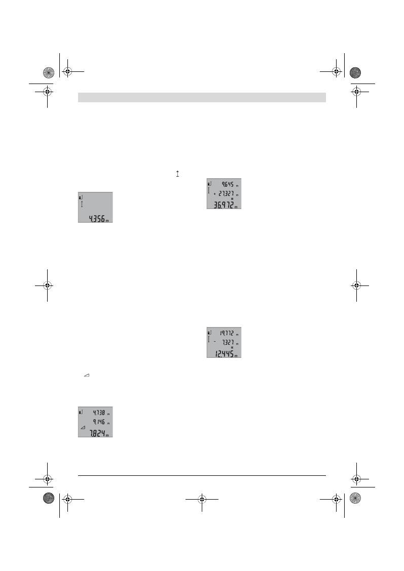
Русский |
107
Bosch Power Tools
2 609 140 773 | (4.12.12)
измеряемый объем на отдельные измерения, которые
можно рассчитать по отдельности и затем сложить.
Продолжительное измерение (см. рис. Е)
При продолжительном измерении измерительный
инструмент можно передвигать относительно цели, при
этом измеренное значение актуализируется прибл. ка-
ждые 0,5 с. Вы можете, напр., передвигаться от стены на
необходимое расстояние, актуальное расстояние всегда
отображается на дисплее.
Для продолжительного измерения нажимайте кнопку
9
до
тех пор, пока на дисплее не появится индикатор продол-
жительного измерения. Чтобы начать продолжительное
измерение, нажмите кнопку измерения
2
.
Текущее измеренное значение появля-
ется в строке результата
b
.
Нажатием кнопки измерения
2
Вы мо-
жете прервать продолжительное изме-
рение. Последнее измеренное значе-
ние появляется в строке результата
b
.
Повторным нажатием кнопки измерения
2
Вы можете сно-
ва начать продолжительное измерение.
Продолжительное измерение автоматически выключает-
ся через 5 мин. Последнее измеренное значение продол-
жает высвечиваться в строке результата
b
.
Косвенное измерение высоты / Простое измерение по
теореме Пифагора (см. рис. F)
Непрямое измерение высоты служит для измерения рас-
стояний, которые невозможно измерить прямым путем,
если на траектории луча существует препятствие или нет
целевой поверхности, служащей в качестве отражателя.
Для получения правильных результатов измерения по-
верхности должны находиться точно под прямым углом
(теорема Пифагора).
Следите за тем, чтобы во время измерения реперная точ-
ка (напр., задний край измерительного инструмента) на-
ходилась при всех отдельных измерениях во время опера-
ции измерения строго на одном и том же месте.
В перерыве между отдельными измерениями лазерный
луч остается включенным.
Нажимайте кнопку
3
до тех пор, пока на дисплее не поя-
вится индикатор простого измерения по теореме Пифаго-
ра .
Измерьте, как и при измерении длины, расстояния
«1»
и
«2»
в указанной последовательности. Следите за тем, что-
бы отрезок
«1»
и измеряемый отрезок
«X»
находились под
прямым углом.
По окончании последнего измерения
результат для искомого отрезка
«X»
отображается в строке результата
b
.
Отдельные измеренные значения ото-
бражаются в строках измеренных зна-
чений
a
.
Удаление измеренных значений
Коротким нажатием кнопки
4
Вы можете удалить послед-
ние измеренные значения во всех режимах. Многократ-
ным коротким нажатием кнопки отдельные измеренные
значения удаляются в обратной последовательности.
Сложение измеренных значений
Чтобы сложить измеренные значения, выполните сначала
любую операцию измерения. Затем нажмите кнопку
«плюс»
8
. Для подтверждения на дисплее появляется
«+»
.
Чтобы сложить значения объема или площади, нажмите
после завершения первой операции измерения кнопку
«плюс»
8
. Для подтверждения на дисплее появляется
«+»
слева от символа объема/площади.
Выполните после этого вторую операцию измерения.
Для опрашивания суммы двух измере-
ний нажмите еще раз кнопку «плюс»
8
.
Расчет суммы отображается в строках
измеренных значений
a
, сумма отобра-
жается в строке результата
b
.
После определения суммы к этому результату можно при-
бавлять другие измеренные значения, если каждый раз
перед операцией измерения будет нажиматься кнопка
«плюс»
8
.
Указания относительно сложения:
– Значения длины, площади и объема нельзя смешивать
при сложении. Если, напр., складываются значения
длины и площади, то при нажатии кнопки «плюс»
8
на
дисплее коротко появляется
«ERROR»
. После этого из-
мерительный инструмент возвращается в предыдущий
режим измерения.
– Прибавляется всегда результат одного измерения
(напр., значение объема), а при продолжительном
измерении – измеренное значение, которое отобра-
жается на дисплее в строке результата
b
. Сложение от-
дельных измеренных значений, отображаемых в стро-
ках измеренных значений
a
, невозможно.
Вычитание измеренных значений
Для вычитания измеренных значений
нажмите кнопку «минус»
5
, в качестве
подтверждения на дисплее появляется
«–»
. Последующие действия аналогич-
ны операциям, описанным в разделе
«Сложение измеренных значений».
Указания по применению
Общие указания
При измерении нельзя закрывать приемную линзу
12
и
выход лазерного излучения
11
.
Во время измерения измерительный инструмент нельзя
передвигать (за исключением режима продолжительного
измерения). Поэтому по возможности положите измери-
тельный инструмент на прочное основание или приставь-
те его к прочному основанию.
Факторы, влияющие на диапазон измерения
Диапазон измерения зависит от условий освещения и от
отражающей способности поверхности цели. Для лучшей
видимости лазерного луча применяйте во время работы
вне помещения и при сильном солнце лазерные очки
19
OBJ_BUCH-1444-004.book Page 107 Tuesday, December 4, 2012 1:47 PM
108
| Русский
2 609 140 773 | (4.12.12)
Bosch Power Tools
(принадлежность) и визирную марку
20
(принадлеж-
ность) или затените визирную марку.
Факторы, влияющие на результат измерения
Из-за физических эффектов не исключено, что при изме-
рении на различных поверхностях могут возникнуть
ошибки измерения. К таким поверхностям относятся:
– прозрачные поверхности (например, стекло, вода),
– отражающие поверхности (например, полированный
металл, стекло),
– пористые поверхности (например, изолирующие мате-
риалы),
– структурированные поверхности (например, пористая
штукатурка, природный камень).
При необходимости применяйте для таких поверхностей
визирную марку
20
(принадлежность).
При косом наведении на цель возможны ошибки.
Воздушные слои с различной температурой и/или непря-
мое отражение также могут отрицательно повлиять на из-
меряемое значение.
Проверка точности измерения расстояния
Чтобы проверить точность измерения расстояния, дейст-
вуйте следующим образом:
– Выберите неизменный отрезок длиной ок. 1 –10 м,
(например, ширина помещения, дверного проема), ве-
личина которого Вам точно известна. Отрезок должен
находиться в помещении, целевая поверхность изме-
рения должна быть ровной и хорошо отражать.
– Измерьте отрезок 10 раз подряд.
Отклонение значений отдельных измерений от среднего
значения не должно превышать ±2 мм. Запротоколируй-
те измерения, чтобы Вы смогли позже сравнить точность.
Работа со штативом (принадлежности)
Применение штатива особенно необходимо для больших
расстояний. Установите измерительный инструмент резь-
бой 1/4"
14
на быстросменную плиту штатива
18
или на
обычный фотоаппаратный штатив. Прочно привинтите ин-
струмент винтом к плите штатива.
Установите исходную плоскость (резьба) для измерения
со штативом, нажав на кнопку
6
.
Неисправность
–
Причины и устранение
Измерительный инструмент проверяет
правильность работы при каждом изме-
рении. При констатации неисправности
на дисплее мигает только показанный ря-
дом символ. В таком случае, а также если
названные выше меры не привели к
успеху, отдайте измерительный инструмент через мага-
зин в сервисную мастерскую фирмы Bosch.
Причина
Устранение
Мигает индикатор предупреждения о выходе за пре-
делы допустимого температурного диапазона (f), из-
мерение невозможно
Температура измерительного
инструмента находится за пре-
делами рабочего диапазона
– 10 °C до +50 °C (в режиме
продолжительного измерения
до +40 °C).
Подождать, пока ин-
струмент не нагреется
или не охладится до ра-
бочей температуры
Индикатор «ERROR» на дисплее
Сложение/вычитание значений
в разных единицах измерения.
Складывать/вычитать
только значения в оди-
наковых единицах из-
мерения
Острый угол между лазерным
лучом и целью.
Увеличить угол между
лазерным лучом и це-
лью
Сильное отражение от по-
верхности цели (например, зер-
кало) или слабое отражение от
поверхности цели (например,
черный материал), или сильное
окружающее освещение.
Используйте визир-
ную марку
20
(при-
надлежности)
Запотевание выхода лазерного
луча
11
или приемной линзы
12
(например, в результате смены
температуры).
Мягкой тряпкой проте-
реть насухо выход
лазерного луча
11
или
приемную линзу
12
Рассчитанное значение превы-
шает 999999 м/м
2
/м
3
.
Разделите расчет на
промежуточные опера-
ции
Непонятный результат измерения
Неодназначное отражение от
поверхности цели (например,
вода, стекло).
Прикрыть поверх-
ность цели
Закрыт выход лазерного луча
11
или приемной линзы
12
.
Открыть выход лазер-
ного луча
11
или при-
емной линзы
12
Установлена неправильная ис-
ходная плоскость
Выбрать правильную
исходную плоскость
Препятствия на пути лазерного
луча
Лазерная точка должна
полностью находиться
на целевой поверхно-
сти
Картинка на дисплее не меняется или измерительный
инструмент реагирует на нажатие кнопок неожидан-
ным образом
Ошибка программного обеспе-
чения
Извлеките батарейки и
снова включите изме-
рительный инструмент
после повторной уста-
новки батареек.
Причина
Устранение
OBJ_BUCH-1444-004.book Page 108 Tuesday, December 4, 2012 1:47 PM
Русский |
109
Bosch Power Tools
2 609 140 773 | (4.12.12)
Техобслуживание и сервис
Техобслуживание и очистка
Храните и переносите измерительный инструмент только
в прилагающемся защитном чехле.
Содержите измерительный инструмент постоянно в чи-
стоте.
Никогда не погружайте измерительный инструмент в воду
или другие жидкости.
Вытирайте загрязнения сухой и мягкой тряпкой. Не
используйте никаких очищающих средств или раствори-
телей.
Ухаживайте за приемной линзой
12
с такой же тщатель-
ностью, с какой Вы ухаживаете за очками или линзой
фотоаппарата.
Если несмотря на тщательную процедуру изготовления и
испытания измерительный инструмент все-таки выйдет из
строя, ремонт должна производить авторизированная
сервисная мастерская для электроинструментов Bosch.
Не вскрывайте самостоятельно измерительный инстру-
мент.
Пожалуйста, во всех запросах и заказах запчастей обяза-
тельно указывайте 10-значный товарный номер по завод-
ской табличке измерительного инструмента.
На ремонт отправляйте измерительный инструмент в за-
щитном чехле
17
.
Сервис и консультирование на предмет ис-
пользования продукции
Сервисная мастерская ответит на все Ваши вопросы по
ремонту и обслуживанию Вашего продукта и по запча-
стям. Монтажные чертежи и информацию по запчастям
Вы найдете также по адресу:
www.bosch-pt.com
Коллектив сотрудников Bosch, предоставляющий кон-
сультации на предмет использования продукции, с удо-
вольствием ответит на все Ваши вопросы относительного
нашей продукции и ее принадлежностей.
Для региона: Россия, Беларусь, Казахстан
Гарантийное обслуживание и ремонт электро-
инструмента, с соблюдением требований и норм изгото-
вителя производятся на территории всех стран только в
фирменных или авторизованных сервисных центрах «Ро-
берт Бош».
ПРЕДУПРЕЖДЕНИЕ! Использование контрафактной про-
дукции опасно в эксплуатации, может привести к ущербу
для Вашего здоровья. Изготовление и распространение
контрафактной продукции преследуется по Закону в ад-
министративном и уголовном порядке.
Россия
ООО «Роберт Бош»
Сервисный центр по обслуживанию электроинструмента
ул. Академика Королева, стр. 13/5
129515, Москва
Россия
Тел.: 8 800 100 8007
E-Mail: pt-service.ru@bosch.com
Полную информацию о расположении сервисных цен-
тров Вы можете получить на официальном сайте
www.bosch-pt.ru либо по телефону справочно-сервисной
службы Bosch 8-800-100-8007 (звонок бесплатный).
Беларусь
ИП «Роберт Бош» ООО
Сервисный центр по обслуживанию электроинструмента
ул. Тимирязева, 65А-020
220035, г. Минск
Беларусь
Тел.: +375 (17) 254 78 71
Тел.: +375 (17) 254 79 15/16
Факс: +375 (17) 254 78 75
E-Mail: pt-service.by@bosch.com
Официальный сайт: www.bosch-pt.by
Казахстан
ТОО «Роберт Бош»
Сервисный центр по обслуживанию электроинструмента
пр. Райымбека/ул. Коммунальная, 169/1
050050 г. Алматы
Казахстан
Тел.: +7 (727) 232 37 07
Факс: +7 (727) 233 07 87
E-Mail: pt-service.ka@bosch.com
Официальный сайт: www.bosch-pt.kz
Утилизация
Отслужившие свой срок измерительные инструменты,
принадлежности и упаковку следует сдавать на экологиче-
ски чистую рекуперацию отходов.
Не выбрасывайте измерительные инструменты и аккуму-
ляторные батареи/батарейки в бытовой мусор!
Только для стран-членов ЕС:
В соответствии с европейской директи-
вой 2002/96/EС отслужившие измери-
тельные инструменты и в соответствии с
европейской директивой 2006/66/ЕС
поврежденные либо отработанные акку-
муляторы/батарейки нужно собирать от-
дельно и сдавать на экологически чистую рекуперацию.
Возможны изменения.
OBJ_BUCH-1444-004.book Page 109 Tuesday, December 4, 2012 1:47 PM
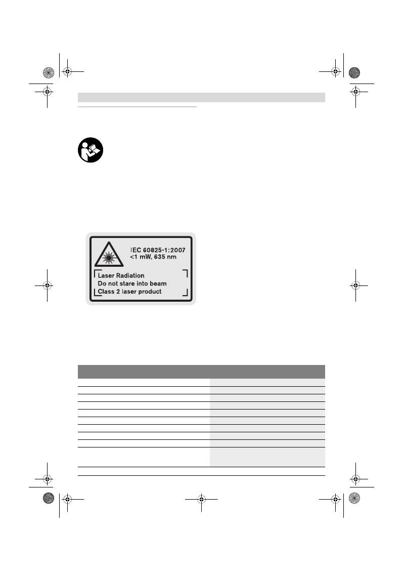
110
| Українська
2 609 140 773 | (4.12.12)
Bosch Power Tools
Українська
Вказівки з техніки безпеки
Прочитайте всі вказівки і дотримуйтеся
їх, щоб працювати з вимірювальним
приладом безпечно та надійно. Ніколи
не доводьте попереджувальні таблички
на вимірювальному інструменті до
невпізнанності. ДОБРЕ ЗБЕРІГАЙТЕ ЇХ.
Обережно – використання засобів обслуговування і
настроювання, що відрізняються від зазначених в
цій інструкції, або використання дозволених засобів
у недозволений спосіб, може призводити до
небезпечених вибухів випромінювання.
Вимірювальний прилад постачається з
попереджувальною табличкою на англійській мові
(на зображенні вимірювального приладу на сторінці
з малюнком вона позначена номером 15.
Перед першим запуском в експлуатацію заклейте
англійський текст попереджувальної таблички
наклейкою на мові Вашої країни, що входить у
комплект постачання.
Не направляйте промінь лазера на людей або
тварин, і самі не дивіться на промінь лазера.
Цей
вимірювальний прилад створює лазерне
випромінювання класу 2 відповідно до норми
IEC 60825-1. Цим випромінюванням можна
ненавмисне засліпити інших людей.
Не використовуйте окуляри для роботи з лазером в
якості захисних окулярів.
Окуляри для роботи з
лазером призначені для кращого розпізнавання
лазерного променя, але вони не захищають від
лазерного проміння.
Не використовуйте окуляри для роботи з лазером
для захисту від сонця і за кермом.
Окуляри для
роботи з лазером не захищають повністю від УФ-
проміння і погіршують розпізнавання кольорів.
Віддавайте свій вимірювальний прилад на ремонт
лише кваліфікованим фахівцям та лише з
використанням оригінальних запчастин.
Тільки за
таких умов Ваш вимірювальний прилад і надалі буде
залишатися безпечним.
Не дозволяйте дітям користуватися без нагляду
лазерним вимірювальним приладом.
Вони можуть
ненавмисне засліпити інших людей.
Не працюйте з вимірювальним приладом у
середовищі, де існує небезпека вибуху внаслідок
присутності горючих рідин, газів або пилу.
У
вимірювальному приладі можуть утворюватися іскри,
від яких може займатися пил або пари.
Опис продукту і послуг
Будь ласка, розгорніть сторінку із зображенням
вимірювального приладу і тримайте її розгорнутою весь
час, поки будете читати інструкцію.
Призначення
Прилад призначений для вимірювання відстані, довжини і
висоти, а також для розрахування площі і об’єму. Вимірю-
вальний прилад придатний для робіт всередині
приміщень та надворі.
Технічні дані
Цифровий лазерний далекомір
GLM 50
Professional
Товарний номер
3 601 K72 2..
Діапазон вимірювання
0,05 –50 м
A)
Точність вимірювання (типова)
±1,5 мм
B)
Найменша одиниця індикації
1 мм
Робоча температура
–10 °C...+50 °C
C)
Температура зберігання
–20 °C...+70 °C
Відносна вологість повітря макс.
90 %
Клас лазера
2
Тип лазера
635 нм, <1 мВт
Діаметр лазерного променя (при 25 °C), прибл.
– на відстані 10 м
– на відстані 50 м
6 мм
35 мм
OBJ_BUCH-1444-004.book Page 110 Tuesday, December 4, 2012 1:47 PM
Українська |
111
Bosch Power Tools
2 609 140 773 | (4.12.12)
Зображені компоненти
Нумерація зображених компонентів посилається на
зображення вимірювального приладу на сторінці з
малюнком.
1
Дисплей
2
Кнопка вимірювання
3
Кнопка вимірювання площі, об’єму і непрямого
вимірювання висоти (теорема Піфагора)
4
Кнопка стирання / вимикач **
5
Кнопка «мінус»
6
Кнопка вибору базової площини
7
Гніздо для шнура для перенесення
8
Кнопка «плюс»
9
Кнопка вимірювання довжини і тривалого
вимірювання
10
Кришка секції для батарейок
11
Вихід лазерного променя
12
Прийомна лінза
13
Серійний номер
14
Різьба 1/4"
15
Попереджувальна табличка для роботи з лазером
16
Фіксатор секції для батарейок
17
Захисна сумка
18
Штатив*
19
Окуляри для роботи з лазером*
20
Візирна марка*
* Зображене чи описане приладдя не належить до
стандартного обсягу поставки.
** Утримуйте кнопку натиснутою, щоб визвати розширені
функції.
Елементи індикації
a
Виміряні значення
b
Результат
c
Режими вимірювання
d
Лазер увімкнутий
e
Базова площина при вимірюванні
f
Індикатор виходу за межі температурного діапазону
g
Індикатор зарядженості батарейок
h
Індикатор помилки
«ERROR»
Монтаж
Вставлення/заміна батарейок
У вимірювальному приладі рекомендується
використовувати лужно-марганцеві батарейки або
акумуляторні батареї.
З акумуляторними батареями на 1,2 В можна виконати
менше вимірювань, ніж з батарейками на 1,5 В.
Щоб відкрити кришку секції для батарейок
10
, натисніть
фіксатор
16
і зніміть кришку секції для батарейок.
Встроміть батарейки або акумуляторні батареї. Слідкуйте
Автоматичне вимикання прибл. через
– Лазер
– Вимірювальний прилад (без вимірювання)
20 с
5 хвил.
Батарейки
Акумуляторні елементи
2 x 1,5 В LR03 (AAA)
2 x 1,2 В HR03 (AAA)
Довговічність батарейок прибл.
– вимірювань
– Тривале вимірювання
10000
D)
2,5 год.
D)
Вага відповідно до EPTA-Procedure 01/2003
0,14 кг
Розмір
53 x 114 x 30 мм
Ступінь захисту
IP 54 (захист від пилу та бризок води)
Цифровий лазерний далекомір
GLM 50
Professional
A) Радіус дії збільшується в залежності від того, наскільки добре лазерне світло відображається від поверхні цілі (у розсіяному, а не у віддзер-
каленому вигляді), а також в залежності від того, наскільки лазерна точка світліша за середовище (внутрішні приміщення, сутінки). За
несприятливих умов (напр, робота надворі при сильному сонячному світлі) може бути необхідним використовувати візирний щит.
B) При вимірюваннях від заднього краю вимірювального приладу. За несприятливих умов, напр., сильне сонячне світло або поверхні, що
погано віддзеркалюють, максимальне відхилення становить
±
10мм на 50 м. За сприятливих умов можна виходити з
±
0,05 мм/м.
C) В режимі тривалого вимірювання макс. робоча температура становить +40
°C
.
D) З акумуляторними елементами на 1,2 В можливо менше вимірювань ніж з батарейками на 1,5 В. Тривалість роботи батарейок зазначена
для вимірювання без підсвічування дисплею.
Для точної ідентифікації вимірювального приладу на заводській табличці позначений серійний номер
13
.
Вимірювання довжини
Тривале вимірювання
Вимірювання площі
Вимірювання об’єму
Просте вимірювання за теоремою Піфагора
OBJ_BUCH-1444-004.book Page 111 Tuesday, December 4, 2012 1:47 PM
112
| Українська
2 609 140 773 | (4.12.12)
Bosch Power Tools
при цьому за правильним розташуванням полюсів, як це
показано всередині секції для батарейок.
При встромлянні батарейок/акумуляторних батарей
зважайте на правильну направленість полюсів, як це
показано в секції для батарейок.
При першому появленні на дисплеї символу батарейок
можливо ще мінімум 100 вимірювань. Функція тривалого
вимірювання вимкнена.
Якщо символ батарейок
мигає, Ви повинні поміняти
батарейки/акумуляторні елементи. Здійснювати
вимірювання більше не можливо.
Завжди міняйте одночасно всі батарейки/акумуляторні
батареї. Використовуйте лише батарейки або
акумуляторні батареї одного виробника і однакової
ємності.
Виймайте батарейки/акумуляторні батареї із
вимірювального приладу, якщо Ви тривалий час не
будете користуватися приладом.
При тривалому
зберіганні батарейки та акумуляторні батареї можуть
кородувати і саморозряджатися.
Експлуатація
Початок роботи
Не залишайте увімкнутий вимірювальний прилад
без догляду, після закінчення роботи вимикайте
вимірювальний прилад.
Інші особи можуть бути
засліплені лазерним променем.
Захищайте вимірювальний прилад від вологи і
сонячних промeнів.
Не допускайте впливу на вимірювальний прилад
екстремальних температур та температурних
перепадів.
Зокрема, не залишайте його на тривалий
час в машині. Якщо вимірювальний прилад зазнав
впливу перепаду температур, перш ніж вмикати його,
дайте йому стабілізувати свою температуру.
Екстремальні температури та температурні перепади
можуть погіршувати точність вимірювального приладу.
Уникайте сильних поштовхів та падіння
вимірювального приладу.
Після сильних зовнішніх
впливів на вимірювальний прилад перед подальшою
роботою з приладом обов’язково перевірте точність
роботи приладу (див. «Перевірка точності
вимірювання відстані», стор. 114).
Вмикання/вимикання
Щоб
увімкнути
вимірювальний прилад, Ви можете:
– натиснути кнопку вимкнення
4
: вимірювальний прилад
вмикається і перебуває в режимі вимірювання
довжини. Лазер не вмикається.
– Натисніть кнопку вимірювання
2
: вимірювальний
інструмент та лазер вмикаються. Вимірювальний
інструмент перебуває в режимі вимірювання довжини.
Не спрямовуйте лазерний промінь на людей і тварин
і не дивіться у лазерний промінь, включаючи і з
великої відстані.
Щоб
вимкнути
вимірювальний прилад, довго натисніть на
кнопку вимкнення
4
.
Якщо протягом прибл. 5 хвил. Ви не будете натискувати ні
на яку кнопку на вимірювальному приладі, прилад, щоб
заощадити батареї, автоматично вимикається.
Процедура вимірювання
Після увімкнення натискуванням кнопки вимірювання
2
вимірювальний інструмент завжди перебуває в режимі
вимірювання довжини. Інший режим вимірювання можна
вибрати, натиснувши на відповідну кнопку (див. «Вимірю-
вальні функції», стор. 113).
В якості базової площини після вмикання встановлений
задній край приладу. Натискаючи на кнопку базової
площини
6
, можна поміняти базову площину (див. «Вибір
базової площини», стор. 112).
Приставте вимірювальний прилад обраною базовою
площиною до бажаної початкової точки вимірювання
(напр., до стіни).
Щоб увімкнути лазерний промінь, коротко натисніть на
кнопку вимірювання
2
.
Не спрямовуйте лазерний промінь на людей і тварин
і не дивіться у лазерний промінь, включаючи і з
великої відстані.
Наведіть лазерний промінь на цільову поверхню. Щоб
здійснити вимірювання, ще раз коротко натисніть на
кнопку вимірювання
2
.
В режимі безперервного вимірювання вимірювання
розпочинається відразу після увімкнення режиму.
Результат вимірювання з’являється звичайно протягом
0,5 сек., макс. через 4 сек. Тривалість вимірювання
залежить від відстані, освітлення і віддзеркалювання від
цільової поверхні. Після закінчення вимірювання
лазерний промінь автоматично вимикається.
Якщо протягом прибл. 20 с після наведення на ціль
вимірювання не здійснюється, лазерний промінь для
заощадження батарейок автоматично вимикається.
Вибір базової площини (див. мал. A)
При вимірюванні Ви можете вибрати одну з трьох базових
площин:
– задній край вимірювального інструменту (напр., при
приставленні до стіни),
– передній край вимірювального приладу (напр., при
вимірюванні від краю стола),
– середина різьби
14
(напр., при вимірюваннях із
штативом).
Щоб змінити базову площину, натискуйте на кнопку
6
до
тих пір, поки на дисплеї не з’явиться необхідна базова
площина. Кожний раз після вмикання в якості базової
площини встановлюється задній край приладу.
Підсвічування дисплея
Підсвічування дисплея активується автоматично в
залежності від зовнішнього світла. Якщо після ввімкнення
підсвічування дисплея не буде натискуватися жодна
OBJ_BUCH-1444-004.book Page 112 Tuesday, December 4, 2012 1:47 PM
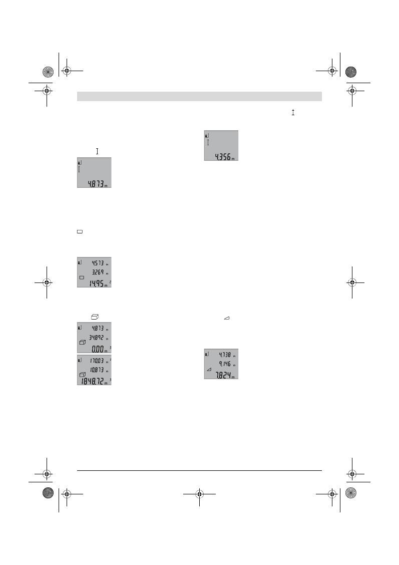
Українська |
113
Bosch Power Tools
2 609 140 773 | (4.12.12)
кнопка, підсвічування тускніє заради заощадження
батарейок.
Вимірювальні функції
Просте вимірювання довжини (див. мал. B)
Для вимірювання довжини натискайте на кнопку
9
до тих
пір, поки на дисплеї не з’явиться індикатор вимірювання
довжини .
Для увімкнення лазера та виконання
вимірювання натисніть один раз
коротко на кнопку вимірювання
2
.
Виміряне значення з’являється в рядку
результату
b
.
Якщо Ви здійснюєте декілька послідовних вимірювань
довжини, то результати останніх вимірювань з’являються
в рядках виміряних значень
a
.
Вимірювання площі (див. мал. C)
Для вимірювання площі натискайте на кнопку
3
до тих пір,
поки на дисплеї не з’явиться індикатор вимірювання площі
.
Після цього проміряйте довжину і ширину як при вимірю-
ванні довжини. В перерві між обома вимірюваннями
лазерний промінь залишається увімкнутим.
Після закінчення другого вимірювання
значення площі автоматично
вираховується і з’являється в рядку ре-
зультату
b
. Окремі значення
вимірювання з’являються в рядках для
виміряних значень
a
.
Вимірювання об’єму (див. мал. D)
Для вимірювання об’єму натискайте на кнопку
3
до тих пір,
поки на дисплеї не з’явиться індикатор вимірювання
об’єму .
Після цього виміряйте довжину,
ширину і висоту, як і при вимірюванні
довжини. В перерві між трьома ви-
мірюваннями лазерний промінь
залишається увімкнутим.
Після закінчення третього
вимірювання прилад автоматично
розраховує об’єм і показує результат у
рядку
b
. Окремі значення вимірювання
з’являються в рядках для виміряних
значень
a
.
Значення, більші за 999999 м
3
, не можуть
відображатися, на дисплеї з’являється
«ERROR»
. Розділіть
вимірюваний об’єм на декілька вимірювань, які б Ви
могли окремо розрахувати і потім скласти.
Тривале вимірювання (див. мал. E)
При тривалому вимірюванні вимірювальний прилад
можна пересувати відносно до цілі, виміряне значення
актуалізується прибл. кожні 0,5 с. Ви можете, напр.,
пересуватися від стіни на бажану відстань, актуальна від-
стань завжди відображається на дисплеї.
Для тривалого вимірювання натискайте на кнопку
9
до тих
пір, поки на дисплеї не з’явиться індикатор тривалого
вимірювання. Щоб почати тривале вимірювання,
натисніть на кнопку вимірювання
2
.
Актуальне виміряне значення
з’являється в рядку результату
b
.
Натисканням на кнопку вимірювання
2
Ви можете закінчити тривале
вимірювання. Останнє виміряне
значення з’являється в рядку
результату
b
. Повторним натисканням на кнопку
вимірювання
2
можна знову розпочати тривале
вимірювання.
Тривале вимірювання автоматично вимикається через
5 хвил. Останнє виміряне значення залишається в рядку
результату
b
.
Непряме вимірювання висоти / Просте вимірювання
за теоремою Піфагора (див. мал. F)
Непряме вимірювання висоти служить для визначення
відстані, яку не можна виміряти безпосередньо, оскільки
на шляху променя знаходиться перешкода або немає
цільової поверхні, що в стані віддзеркалювати. Для
досягнення найкращих результатів під час вимірювання
поверхні повинні знаходитися точно під прямим кутом
(теорема Піфагора).
Слідкуйте за тим, щоб під час окремих вимірювань
реперна точка вимірювання (напр., задній край
вимірювального інструменту) знаходилася точно на тому
самому місці.
В перерві між окремими вимірюваннями лазерний
промінь залишається увімкнутим.
Натискайте на кнопку
3
до тих пір, поки на дисплеї не
з’явиться індикатор простого вимірювання за теоремою
Піфагора .
Виміряйте, як і при вимірюванні довжини, відрізки
«1»
та
«2»
в зазначеній послідовності. Слідкуйте за тим, щоб
відрізок
«1»
та вимірюваний відрізок
«X»
знаходилися під
прямим кутом.
Після закінчення останнього
вимірювання результат для
вимірюваного відрізка
«X»
з’являється
в рядку результату
b
. Окремі значення
вимірювання з’являються в рядках для
виміряних значень
a
.
Стирання виміряних значень
Коротким натисканням на кнопку
4
можна видалити всі
останні результати одиночних вимірювань незалежно від
режиму вимірювання. Багаторазовим коротким натискан-
ням всі результати одиночних вимірювань витираються у
зворотному порядку.
Додавання виміряних значень
Щоб додати виміряні значення, виконайте спочатку будь-
яку операцію вимірювання. Потім натисніть кнопку
«плюс»
8
. Для підтвердження на дисплеї з’являється
«+»
.
Щоб додати значення об’єму або площі, натисніть після
закінчення першої операції вимірювання кнопку «плюс»
OBJ_BUCH-1444-004.book Page 113 Tuesday, December 4, 2012 1:47 PM
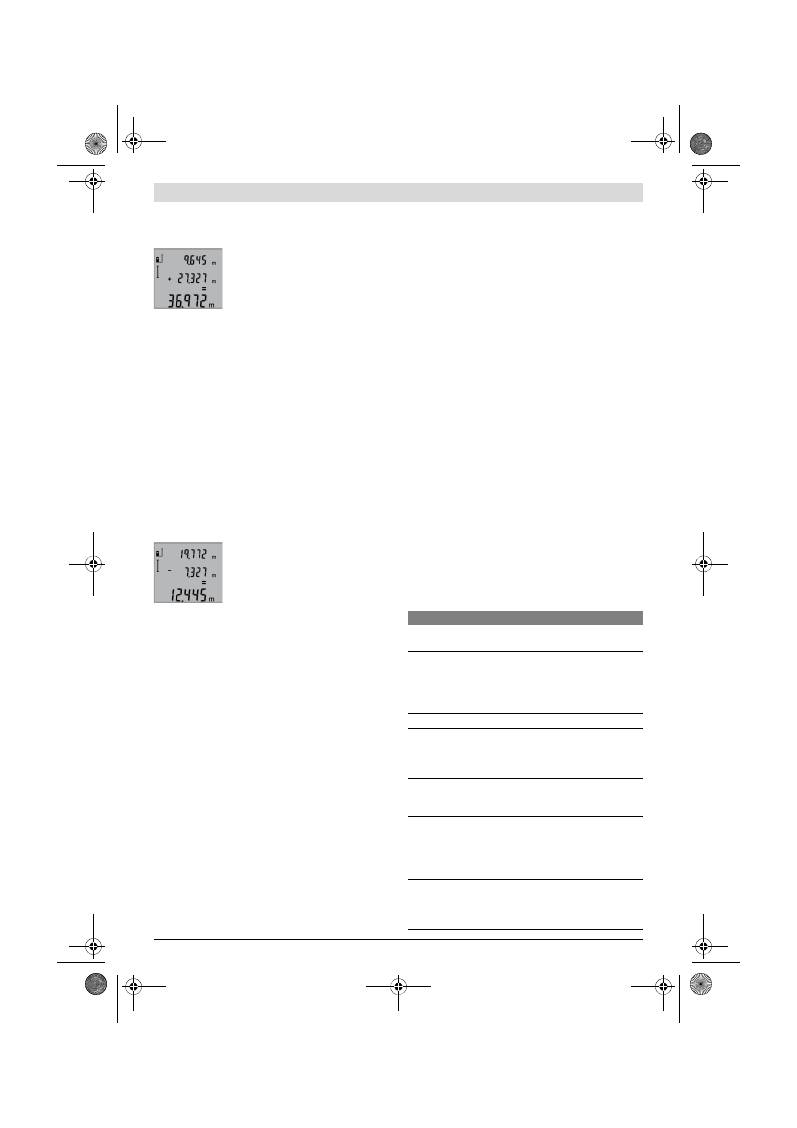
114
| Українська
2 609 140 773 | (4.12.12)
Bosch Power Tools
8
. Для підтвердження на дисплеї з’являється
«+»
ліворуч
від символу об’єму/площі.
Виконайте після цього другу операцію вимірювання.
Для опитування суми обох операцій
вимірювання натисніть іще раз кнопку
«плюс»
8
. Розрахунок з’являється в
рядку виміряних значень
a
, а сума – в
рядку результату
b
.
Після підрахунку суми до цього результату можна
додавати інші значення вимірювання, якщо кожного разу
перед операцією вимірювання буде натискуватися кнопка
«плюс»
8
.
Вказівки щодо додавання:
– Значення довжини, площі та об’єму не можна змішувати
при додаванні. Якщо, напр., будуть додаватися значення
довжини та площі, при натискуванні кнопки «плюс»
8
на
дисплеї коротко з’явиться
«ERROR»
. Після цього
вимірювальний прилад повертається в попередній
режим вимірювання.
– Додається завжди значення одного вимірювання
(напр., значення об’єму), а при тривалому
вимірюванні – виміряне значення, що відображається
на дисплеї в рядку результату
b
. Додавання окремих
виміряних значень із рядків виміряних значень
a
не
можливе.
Віднімання виміряних значень
Для віднімання виміряних значень
натисніть кнопку «мінус»
5
, для
підтвердження на дисплеї з’являється
«–»
. Наступні операції аналогічні
операціям, описаним в розділі
«Додавання виміряних значень».
Вказівки щодо роботи
Загальні вказівки
Прийомна лінза
12
і місце виходу лазерного променя
11
під час вимірювання повинні бути відкриті.
Під час вимірювання не можна пересувати
вимірювальний інструмент (виняток: функція тривалого
вимірювання). Тому за можливістю покладіть
вимірювальний інструмент на міцну опорну поверхню.
Фактори впливу на діапазон вимірювання
На діапазон вимірювання впливає освітлення і
віддзеркалювання від цільової поверхні. Щоб при роботах
надворі або при сильному сонці краще було видно
лазерний промінь, користуйтеся окулярами для роботи з
лазером
19
(приладдя) і візирним щитом
20
(приладдя)
або затініть цільову поверхню.
Фактори впливу на результат вимірювання
Зважаючи на фізичні ефекти, не можна виключити
помилки в результатах вимірювання при вимірюваннях на
різних поверхнях. Сюди відносяться:
– прозорі поверхні (напр., скло, вода),
– поверхні, що віддзеркалюють (напр., полірований
метал, скло),
– пористі поверхні (напр., ізоляційні матеріали),
– структуровані поверхні (напр., структурована
штукатурка, природній будівельний камінь).
За необхідністю використовуйте на таких поверхнях візир-
ний щит
20
(приладдя).
При косому наведенні на ціль можливі помилки.
Крім того, на результат вимірювання можуть впливати
шари повітря з різною температурою або непряме
віддзеркалювання.
Перевірка точності вимірювання відстані
Точність вимірювання відстані можна перевірити таким
чином:
– Виберіть ділянку довжиною прибл. 1 – 10 м (напр.,
ширина приміщення, дверний проріз), розмір якої вам
добре відомий. Ділянка має знаходиться в приміщенні,
цільова поверхня вимірювання має бути рівною і добре
віддзеркалювати.
– Промірте цю ділянку 10 разів підряд.
Відхилення окремих значень вимірювань від середнього
значення не повинно перевищувати ±2 мм.
Запротоколюйте вимірювання, щоб пізніше можна було
порівняти точність.
Робота зі штативом (приладдя)
Штатив особливо необхідний при роботах на великій
відстані. Надіньте вимірювальний прилад різьбою 1/4"
14
на швидкозмінну пластину штатива
18
або звичайного
фотоштатива. Прикрутіть його фіксуючим гвинтом на
швидкозмінній пластині.
Натисканням на кнопку
6
задайте базову площину для
вимірювань із штативом (базова площина: різьба).
Неполадки
–
причини і усунення
Причина
Що робити
Мигає індикатор виходу за межі температурного
діапазону (f), вимірювання не можливе
Температура вимірювального
приладу вийшла за межі робочої
температури від – 10 °C до
+50 °C (у режимі тривалого
вимірювання до +40 °C).
Зачекайте, поки вимі-
рювальний прилад не
досягне робочої тем-
ператури
Індикатор «ERROR» на дисплеї
Додавання/віднімання
виміряних значень в різних
одиницях
Додавайте/віднімайте
лише виміряні значен-
ня в однакових одини-
цях
Кут між лазерним променем і
ціллю занадто гострий.
Збільшіть кут між ла-
зерним променем і
ціллю
Цільова поверхня занадто від-
дзеркалює (напр., дзеркало) або
занадто слабка (напр., чорна
тканина) або зовнішнє світло
занадто сильне.
Використовуйте візир-
ний щит
20
(приладдя)
Вихід лазерного променя
11
або
прийомна лінза
12
спітніли
(напр., внаслідок швидкого пе-
репаду температури).
Протріть м’якою ган-
чіркою вихід лазерного
променя
11
або при-
йомну лінзу
12
OBJ_BUCH-1444-004.book Page 114 Tuesday, December 4, 2012 1:47 PM
Українська |
115
Bosch Power Tools
2 609 140 773 | (4.12.12)
Вимірювальний прилад спостерігає за
правильним функціонуванням при
кожному вимірюванні. При виявленні
неполадки на дисплеї мигає лише зобра-
жений символ. В такому випадку або
якщо вищезазначені заходи з усунення
неполадки не допомагають, передайте свій вимірю-
вальний прилад через магазин в сервісну майстерню
Bosch.
Технічне обслуговування і сервіс
Технічне обслуговування і очищення
Зберігайте і переносьте вимірювальний прилад лише в
захисній сумці, яка іде в комплекті.
Завжди тримайте вимірювальний прилад в чистоті.
Не занурюйте вимірювальний прилад у воду або інші
рідини.
Витирайте забруднення вологою м’якою ганчіркою. Не
користуйтеся мийними засобами і розчинниками.
Добре доглядайте за прийомною лінзою
12
, як начебто це
були окуляри або лінза фотоапарата.
Якщо незважаючи на ретельну процедуру виготовлення і
випробування вимірювальний прилад все-таки вийде з
ладу, ремонт має виконувати лише майстерня,
авторизована для електроінструментів Bosch. Не
відкривайте самостійно вимірювальний інструмент.
При будь-яких запитаннях і замовленні запчастин, будь
ласка, обов’язково зазначайте 10-значний товарний
номер, що знаходиться на заводській табличці
вимірювального приладу.
Надсилайте вимірювальний прилад на ремонт в захисній
сумці
17
.
Сервіс та надання консультацій щодо
використання продукції
Сервісна майстерня відповість на запитання стосовно
ремонту і технічного обслуговування Вашого виробу.
Малюнки в деталях і інформацію щодо запчастин можна
знайти за адресою:
www.bosch-pt.com
Команда співробітників Bosch з надання консультацій
щодо використання продукції із задоволенням відповість
на Ваші запитання стосовно нашої продукції та приладдя
до неї.
Гарантійне обслуговування і ремонт електроінструменту
здійснюються відповідно до вимог і норм виготовлювача
на території всіх країн лише у фірмових або
авторизованих сервісних центрах фірми «Роберт Бош».
ПОПЕРЕДЖЕННЯ! Використання контрафактної продукції
небезпечне в експлуатації і може мати негативні наслідки
для здоров’я. Виготовлення і розповсюдження
контрафактної продукції переслідується за Законом в
адміністративному і кримінальному порядку.
Україна
ТОВ «Роберт Бош»
Cервісний центр електроінструментів
вул. Крайня, 1, 02660, Київ-60
Україна
Тел.: (044) 4 90 24 07 (багатоканальний)
E-Mail: pt-service.ua@bosch.com
Офіційний сайт: www.bosch-powertools.com.ua
Адреса Регіональних гарантійних сервісних майстерень
зазначена в Національному гарантійному талоні.
Утилізація
Вимірювальні прилади, приладдя і упаковку треба здавати
на екологічно чисту повторну переробку.
Не викидайте вимірювальні інструменти та акумуляторні
батареї/батарейки в побутове сміття!
Лише для країн ЄС:
Відповідно до європейської директиви
2002/96/ЄC та європейської директиви
2006/66/ЄC відпрацьовані
вимірювальні прилади, пошкоджені або
відпрацьовані акумуляторні батареї/
батарейки повинні здаватися окремо і
утилізуватися екологічно чистим
способом.
Можливі зміни.
Розраховане значення більше за
999999 м/м
2
/м
3
.
Розділіть розрахунок
на декілька проміжних
операцій
Результат вимірювання неправдоподібний
Цільова поверхня віддзеркалює
не однозначно (напр., вода,
скло).
Накрийте цільову
поверхню
Закритий вихід лазерного про-
меня
11
або прийомна лінза
12
.
Вихід лазерного про-
меня
11
або прийомна
лінза
12
мають залиша-
тися відкритими
Встановлена неправильна
базова площина
Встановіть базову
площину, що від-
повідає здійсню-
ваному вимірюванню
Перешкода на шляху лазерного
променя
Лазерна точка має
повністю знаходиться
на цільовій поверхні.
Зображення на дисплеї залишається незмінним або
вимірювальний прилад реагує на натискування
кнопок несподіваним чином
Помилка в програмному
забезпеченні
Вийміть батарейки та
знову увімкніть
вимірювальний
інструмент після
повторного
установлення
батарейок.
Причина
Що робити
OBJ_BUCH-1444-004.book Page 115 Tuesday, December 4, 2012 1:47 PM
116
| Română
2 609 140 773 | (4.12.12)
Bosch Power Tools
Română
Instrucţiuni privind siguranţa şi pro-
tecţia muncii
Pentru a putea lucra nepericulos şi sigur cu
aparatul de măsură, trebuie să citiţi şi să
respectaţi toate instrucţiunile. Nu distru-
geţi niciodată plăcuţele de avertizare ale a-
paratului de măsură, făcându-le de nerecu-
noscut. PĂSTRAŢI ÎN CONDIŢII BUNE PRE-
ZENTELE INSTRUCŢIUNI.
Atenţie – în cazul în care se folosesc alte dispozitive de
comandă sau de ajustare decât cele indicate în prezen-
ta sau dacă se execută alte proceduri, acest lucru poate
duce la o expunere periculoasă la radiaţii.
Aparatul de măsură se livrează cu o plăcuţă de avertiza-
re în limba engleză (în schiţa aparatului de măsură de la
pagina grafică evidenţiată cu numărul 15).
Înainte de prima punere în funcţiune, lipiţi deasupra
textului în limba engleză al plăcuţei de avertizare, eti-
cheta în limba ţării dumneavoastră, din setul de livrare.
Nu îndreptaţi raza laser asupra persoanelor sau anima-
lelor şi nu priviţi nici dumneavoastră spre aceasta.
Apa-
ratul de măsură generează raze laser din clasa laser 2 con-
form IEC 60825-1. Acestea pot provoca orbirea persoa-
nelor.
Nu folosiţi ochelarii pentru laser drept ochelari de pro-
tecţie.
Ochelarii pentru laser servesc la mai buna recu-
noaştere a razei laser, dar nu vă protejează totuşi împotriva
radiaţiei laser.
Nu folosiţi ochelarii pentru laser drept ochelari de soa-
re sau în traficul rutier.
Ochelarii pentru laser nu vă oferă
protecţie totală împotriva razelor ultraviolete şi vă diminu-
ează gradul de percepţie a culorilor.
Nu permiteţi repararea aparatului de măsură decât de
către personal de specialitate corespunzător calificat
şi numai cu piese de schimb originale.
Numai în acest
mod poate fi garantată siguranţa de exploatare a aparatului
de măsură.
Nu permiteţi copiilor să folosească nesupravegheaţi a-
paratul de măsură cu laser.
Ei pot provoca în mod acci-
dental orbirea persoanelor.
Nu lucraţi cu aparatul de măsură în mediu cu pericol de
explozie în care se află lichide, gaze sau pulberi infla-
mabile.
În aparatul de măsură se pot produce scântei care
să aprindă praful sau vaporii.
Descrierea produsului şi a performan-
ţelor
Vă rugăm să desfaceţi pagina pliantă cu ilustrarea aparatului
de măsură şi să o lăsaţi desfăcută cât timp citiţi instrucţiunile
de folosire.
Utilizare conform destinaţiei
Aparatul de măsură este destinat măsurării depărtărilor, lun-
gimilor, înălţimilor, distanţelor cât şi calculării suprafeţelor şi
volumelor. Aparatul de măsură este adecvat pentru măsu-
rători în mediu interior şi exterior.
Date tehnice
Telemetru digital cu laser
GLM 50
Professional
Număr de identificare
3 601 K72 2..
Domeniu de măsurare
0,05 –50 m
A)
Precizie de măsurare (normală)
±1,5 mm
B)
Cea mai mică unitate afişată
1 mm
Temperatură de lucru
–10 °C...+50 °C
C)
Temperatură de depozitare
–20 °C...+70 °C
Umiditate relativă maximă a aerului
90 %
Clasa laser
2
Tip laser
635 nm, <1 mW
Diametru rază laser (la 25 °C) aprox.
– la o distanţă de 10 m
– la o distanţă de 50 m
6 mm
35 mm
OBJ_BUCH-1444-004.book Page 116 Tuesday, December 4, 2012 1:47 PM

Română |
117
Bosch Power Tools
2 609 140 773 | (4.12.12)
Elemente componente
Numerotarea componentelor ilustrate se referă la schiţa de la
pagina grafică.
1
Display
2
Tastă de măsurare
3
Tastă pentru măsurarea suprafeţelor, volumelor şi măsu-
rarea indirectă a înălţimilor (Pitagora)
4
Tastă de ştergere / tastă pornit-oprit **
5
Tastă minus
6
Tastă de selecţie a planului de referinţă
7
Clemă de prindere chingă de transport
8
Tastă plus
9
Tastă pentru măsurarea lungimilor şi pentru măsurare
continuă
10
Capac compartiment baterie
11
Ieşire radiaţie laser
12
Lentilă receptoare
13
Număr de serie
14
Filet de 1/4"
15
Plăcuţă de avertizare laser
16
Dispozitiv de blocare compartiment baterie
17
Geantă de protecţie
18
Stativ*
19
Ochelari optici pentru laser*
20
Panou de vizare laser*
* Accesoriile ilustrate sau descrise nu sunt incluse în setul de livra-
re standard.
** A se ţine tasta apăsată pentru apelarea funcţiilor extinse.
Elemente afişaj
a
Rânduri valori măsurate
b
Rând de rezultate
c
Funcţii de măsurare
d
Laser conectat
e
Plan de referinţă la măsurare
f
Avertizare temperatură
g
Avertizare baterii descărcate
h
Mesaj de eroare
„ERROR“
Montare
Montarea/schimbarea bateriilor
Pentru buna funcţionare a aparatului de măsură se recoman-
dă utilizarea bateriilor alcaline cu mangan sau a acumulatori-
lor.
Cu acumulatorii de 1,2 V sunt posibile mai puţine măsurători
decât cu bateriile de 1,5 V.
Pentru a deschide capacul compartimentului de baterii
10
a-
păsaţi dispozitivul de blocare
16
şi scoateţi capacul compar-
timentului de baterii. Introduceţi bateriile respectiv acumula-
Deconectare automată după aprox.
– Laser
– Aparat de măsurare (fără măsurare)
20 s
5 min
Baterii
Celule de acumulator
2 x 1,5 V LR03 (AAA)
2 x 1,2 V HR03 (AAA)
Durată de utilizare baterie aprox.
– Măsurări individuale
– Măsurare continuă
10000
D)
2,5 h
D)
Greutate conform EPTA-Procedure 01/2003
0,14 kg
Dimensiuni
53 x 114 x 30 mm
Tip de protecţie
IP 54 (protejat împotriva prafului şi a stropilor de apă)
Telemetru digital cu laser
GLM 50
Professional
A) Raza de acţiune creşte în funcţie de cât de bine este redirecţionată înapoi lumina laserului de către suprafaţa ţintă (prin difuzare, nu prin reflexie) şi
în funcţie de cât de puternică este luminozitatea punctului laser comparativ cu lumina ambiantă (spaţii interioare, amurg). În caz de condiţii nefavora-
bile (de exemplu măsurare în mediu exterior, cu radiaţii solare puternice) poate fi necesară utilizarea panoului de vizare.
B) Pentru măsurători efectuate de pe marginea posterioară a aparatului de măsură. În caz de condiţii nefavorabile ca de ex. radiaţii solare puternice sau
suprafeţe cu reflexie slabă, abaterea maximă este de
±
10 mm la 50 m. În caz de condiţii favorabile marja de eroare este de
±
0,05 mm/m.
C) În funcţia de măsurare continuă temperatura maximă de funcţionare este de +40
°C
.
D) Cu celulele de acumulator de 1,2 V sunt posibile mai puţine măsurători decât cu bateriile de 1,5 V. Durata de viaţă specificată a bateriilor se referă
la măsurători efectuate fără iluminarea display-ului.
Numărul de serie
13
de pe plăcuţa indicatoare a tipului serveşte la identificarea aparatului dumneavoastră de măsură.
Măsurarea lungimilor
Măsurare continuă
Măsurarea suprafeţelor
Măsurarea volumelor
Măsurătoare Pitagora simplă
OBJ_BUCH-1444-004.book Page 117 Tuesday, December 4, 2012 1:47 PM
118
| Română
2 609 140 773 | (4.12.12)
Bosch Power Tools
torii. Respectaţi polaritatea corectă conform schiţei din inte-
riorul compartimentului de baterii.
La introducerea bateriilor respectiv a acumulatorilor respec-
taţi polaritatea corectă, conform schiţei din compartimentul
de baterii.
Atunci când simboulul de baterie
apare prima dată pe dis-
play, mai sunt posibile încă cel puţin 100 măsurători individu-
ale. Funcţia de măsurare continuă este dezactivată.
Atunci când simbolul de baterie
clipeşte, trebuie să schim-
baţi bateriile resp. celulele de acumulator. Nu mai sunt posibi-
le măsurători.
Înlocuiţi întotdeauna toate bateriile resp. acumulatorii în ace-
laşi timp. Folosiţi numai baterii sau acumulatori de aceeaşi fa-
bricaţie şi având aceeaşi capacitate.
Extrageţi bateriile resp. acumulatorii din aparatul de
măsură, atunci când nu-l veţi folosi un timp mai înde-
lungat.
În cazul unei depozitări mai îndelungate, bateriile
şi acumulatorii se pot coroda şi autodescărca.
Funcţionare
Punere în funcţiune
Nu lăsaţi nesupraveghiat aparatul de măsură pornit şi
deconectaţi-l după utilizare.
Alte persoane ar putea fi or-
bite de raza laser.
Feriţi aparatul de măsură de umezeală şi de expunere
directă la radiaţii solare.
Nu expuneţi aparatul de măsură unor temperaturi sau
unor variaţii extreme de temperatură.
De ex. nu-l lăsaţi
prea mult timp în autoturism. În cazul unor variaţii mai mari
de temperatură lăsaţi mai întâi aparatul să se acomodeze
înainte de a-l pune în funcţiune. Temperaturile sau variaţii-
le extreme de temperatură pot afecta precizia aparatului
de măsură.
Evitaţi şocurile puternice sau căderile aparatului de
măsură.
După influenţe exterioare puternice, înainte de a
continua lucrul, ar trebui să efectuaţi o verificare a preciziei
(vezi „Verificarea preciziei de măsurare a distanţelor“,
pagina 120).
Conectare/deconectare
Pentru
conectarea
aparatului de măsură aveţi următoarele
posibilităţi:
– Apăsaţi tasta pornit-oprit
4
: aparatul de măsură este co-
nectat şi se află în funcţia de măsurare a lungimilor. Laserul
nu este conectat.
– Apăsaţi tasta de măsurare
2
: Aparatul de măsură şi laserul
sunt conectate. Aparatul de măsură se află în funcţia de
măsurare a lungimilor.
Nu îndreptaţi raza laser asupra persoanelor sau anima-
lelor şi nu priviţi direct în raza laser, nici chiar de la dis-
tanţă mai mare.
Pentru
deconectarea
aparatului de măsură apăsaţi un timp
îndelungat tasta pornit-oprit
4
.
Dacă timp de aprox. 5 min nu se apasă nicio tastă la aparatul
de măsură, acesta se va deconecta automat, pentru menaja-
rea bateriilor.
Procesul de măsurare
După ce a fost conectat prin apăsarea tastei de măsurare
2
a-
paratul de măsură se află în continuare. în fucţia de măsurare
a lungimilor. Alte funcţii de măsurare pot fi setate prin apăsa-
rea tastei alocate funcţiei respective (vezi „Funcţii de măsura-
re“, pagina 118).
După conectare este selectată ca plan de referinţă marginea
posterioară a aparatului de măsură. Puteţi schimba planul de
referinţă apăsând tasta planului de referinţă
6
(vezi „Selecta-
rea planului de referinţă“, pagina 118).
Aşezaţi aparatul de măsură sprijinindu-l cu planul de referinţă
selectat în punctul de pornire dorit pentru măsurare (de
exemplu peretele).
Pentru conectarea razei laser apăsaţi scurt tasta de măsurare
2
.
Nu îndreptaţi raza laser asupra persoanelor sau anima-
lelor şi nu priviţi direct în raza laser, nici chiar de la dis-
tanţă mai mare.
Vizaţi cu raza laser suprafaţa ţintă. Pentru declanşarea măsu-
rării apăsaţi din nou scurt tasta de măsurare
2
.
În funcţia de măsurare continuă, măsurarea începe imediat
după activarea funcţiei.
Valoarea măsurată apare în mod normal în interval de 0,5 s şi
cel mai târziu după 4 s. Durata măsurătorii depinde de distan-
ţă, condiţiile de luminozitate şi calităţile de reflexie ale supra-
feţei ţintă. După terminarea măsurării raza laser se deconec-
tează automat.
Dacă, după vizare, timp de aprox. 20 s nu are loc nici o măsu-
rare, raza laser se deconectează automat, pentru menajarea
bateriilor.
Selectarea planului de referinţă (vezi figura A)
Pentru măsurare puteţi alege între trei planuri de referinţă di-
ferite:
– marginea posterioară a aparatului de măsură (de exemplu
în cazul aşezării aparatului de măsură pe un perete),
– maginea anterioară a aparatului de măsură (de exemplu la
măsurarea de pe o margine a mesei),
– mijlocul filetului
14
(de exemplu pentru măsurători cu sta-
tiv).
Pentru selecţia planului de referinţă apăsaţi tasta
6
de atâtea
ori până când pe display va fi afişat planul de referinţă dorit.
După conectare, este presetată ca plan de referinţă marginea
posterioară a aparatului de măsură.
Iluminare display
Iluminarea display-ului se activează automat în funcţie de lu-
mina ambiantă. Dacă după conectarea iluminării display-ului
nu se apasă nicio tastă, lumina se estompează, pentru mena-
jarea bateriilor.
Funcţii de măsurare
Măsurare simplă a lungimilor (vezi figura B)
Pentru măsurarea lungimilor apăsaţi tasta
9
de atâtea ori cât
este necesar ca pe display să apară indicatorul pentru măsu-
rarea lungimilor .
OBJ_BUCH-1444-004.book Page 118 Tuesday, December 4, 2012 1:47 PM
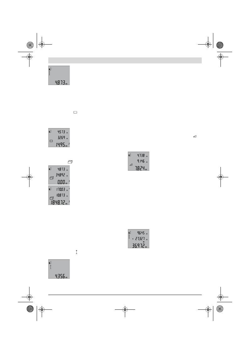
Română |
119
Bosch Power Tools
2 609 140 773 | (4.12.12)
Pentru conectarea laserului şi pentru mă-
surare apăsaţi câte o dată scurt tasta de
măsurare
2
.
Valorea măsurată va fi afişată pe rândul
de rezultate
b
.
În cazul unor măsurători succesive de lungimi pe rândurile va-
lorilor măsurate
a
vor fi afişate rezultatele ultimelor măsură-
tori.
Măsurarea suprafeţelor (vezi figura C)
Pentru măsurarea suprafeţelor apăsaţi tasta
3
de atâtea ori
cât este necesar ca pe display să apară indicatorul pentru mă-
surarea suprafeţelor
.
Măsuraţi apoi consecutiv lungimea şi lăţimea, întocmai ca la o
măsurare de lungimi. Între cele două măsurători raza laser ră-
mâne conectată.
După terminarea celei de a doua măsură-
tori suprafaţa este calculată automat şi
afişată pe rândul de rezultate
b
. Valorile
măsurate individuale apar pe rândurile
valorilor măsurate
a
.
Măsurarea volumelor (vezi figura D)
Pentru măsurarea volumelor apăsaţi tasta
3
de atâtea ori cât
este necesar ca pe display să apară indicatorul pentru măsu-
rarea volumelor
.
Măsuraţi în continuare consecutiv lungi-
mea, lăţimea şi înălţimea, întocmai ca la o
măsurare de lungimi. Raza laser rămâne
conectată între cele trei măsurători.
După terminarea celei de a treia măsură-
tori volumul este calculat în mod automat
şi afişat pe rândul de rezultate
b
. Valorile
măsurate individuale apar pe rândurile
valorilor măsurate
a
.
Valorile de peste 999999 m
3
nu pot fi afişate, pe display apa-
re
„ERROR“
. Împărţiţi volumele care trebuie măsurate în mai
multe măsurători ale căror valori să le calculaţi separat şi apoi
să le adunaţi.
Măsurare continuă (vezi figura E)
În cadrul măsurării continue aparatul de măsură poate fi
deplasat faţă de ţintă, în acest caz valoarea măsurată actuali-
zându-se la interval de aprox. 0,5 s. Puteţi de ex. să vă înde-
părtaţi de un perete până la distanţa dorită, în acest timp dis-
tanţa curentă putând fi citită în orice moment la aparat.
Pentru măsurători continue apăsaţi tasta
9
, până când pe dis-
play apare indicatorul pentru măsurare continuă. Pentru
începerea măsurării continue apăsaţi tasta de măsurare
2
.
Valoara măsurată curentă va fi afişată pe
rândul de rezultate
b
.
Prin apăsarea tastei de măsurare
2
veţi în-
chieia măsurarea continuă. Ultima valoa-
re măsurată va fi afişată pe rândul de re-
zultate
b
. Printr-o nouă apăsare a tastei
de măsurare
2
măsurarea continuă va fi reluată de la început.
Măsurarea continuă se întrerupe automat după 5 min. Ultima
valoare măsurată rămâne afişată pe rândul de rezultate
b
.
Măsurare indirectă a înălţimilor / Măsurătoare Pitagora
simplă (vezi figura F)
Măsurarea indirectă a înălţimilor serveşte la determinarea
distanţelor care nu pot fi măsurate direct, din cauză că un ob-
stacol obstrucţionează traiectoria razei sau pentru că nu este
disponibilă o suprafaţă ţintă reflectantă. Se vor obţine rezul-
tate corecte numai în cazul în care se va păstra acurateţea un-
ghiurilor drepte cerute la fiecare măsurătoare în parte (teore-
ma lui Pitagora).
Aveţi grijă ca punctul de referinţă (de exemplu marginea pos-
terioară a aparatului de măsură) să rămână exact în acelaşi loc
la toate măsurătorile individuale din cadrul unui proces de
măsurare.
Raza laser rămâne conectată între măsurătorile individuale.
Apăsaţi tasta
3
de atâtea ori cât este necesar ca pe display să
apară indicatorul pentru măsurătoare Pitagora simplă
.
Măsuraţi întocmai ca la o măsurătoare de lungime distanţele
„1“
şi
„2“
în această succesiune. Aveţi grijă ca distanţa
„1“
şi
distanţa căutată
„X“
să formeze un unghi drept.
După terminarea ultimei măsurători, re-
zultatul obţinut pentru distanţa căutată
„X“
va fi afişat pe rândul de rezultate
b
.
Valorile măsurate individuale vor fi afişate
pe rândul valorilor măsurate
a
.
Ştergerea valorii măsurate
În toate funcţiile de măsurare, puteţi şterge ultima valoare mă-
surată, printr-o scurtă apăsare a tastei
4
. Apăsând scurt, de
mai multe ori tasta, veţi putea şterge din memorie valorile mă-
surate, în ordine inversă a determinării lor.
Adunarea valorilor măsurate
Pentru adunarea valorilor măsurate, efectuaţi mai întâi o mă-
surătoare la alegere. Apăsaţi apoi tasta plus
8
. Pe display apa-
re pentru confirmare
„+“
.
Pentru adunarea volumelor sau suprafeţelor, după termina-
rea primului proces de măsurare apăsaţi tasta plus
8
. Pe dis-
play apare pentru confirmare
„+“
în partea stângă a simbolu-
lui de volum/suprafaţă.
Efectuaţi apoi o a doua măsurătoare.
Pentru obţinerea sumei celor două măsu-
rători apăsaţi din nou tasta plus
8
. Calcu-
lul va fi afişat pe rândurile valorilor măsu-
rate
a
, suma se va afla pe rândul de rezul-
tate
b
.
După calcularea sumei, la acest rezultat vor putea fi adăugate
şi alte valori măsurate, condiţia fiind ca înainte de măsurătoa-
rea respectivă să se apese tasta plus
8
.
Indicaţii pentru adunare:
– Lungimile, suprafeţele şi volumele nu pot fi adunate ames-
tecat. De exemplu, dacă se adună o lungime cu o suprafaţă,
la apăsarea tastei plus
8
pe display va apărea scurt mesajul
„ERROR“
. Apoi aparatul de măsură comută în ultima fucc-
ţie de măsurare care a fost activată.
– Se adună de fiecare dată rezultatul unei singure măsurători
(de ex. volumul), iar la măsurările continue, valoarea mă-
OBJ_BUCH-1444-004.book Page 119 Tuesday, December 4, 2012 1:47 PM
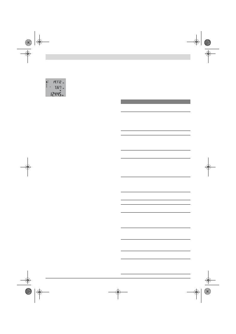
120
| Română
2 609 140 773 | (4.12.12)
Bosch Power Tools
surată afişată pe rândul de rezultate
b
. Nu este posibilă a-
dunarea valorilor măsurate individuale de pe rândurile va-
lorilor măsurate
a
.
Scăderea valorii măsurate
Pentru scăderea valorilor măsurate apă-
saţi tasta minus
5
, pe display apare pen-
tru confirmare
„–“
. În continuare se pro-
cedează analog secţiunii „Adunarea valo-
rilor măsurate“.
Instrucţiuni de lucru
Indicaţii de ordin general
Lentila receptoare
12
şi orificiul de ieşire a radiaţiei laser
11
nu trebuie să fie acoperite în timpul măsurării.
Nu este permis ca aparatul de măsură să fie mişcat în timpul
unei măsurători (cu excepţia funcţiei de măsurare continuă).
De aceea, aşezaţi aparatul de măsură pe cât posibil pe o su-
prafaţă tare de oprire sau de sprijin.
Influenţe asupra domeniului de măsurare
Domeniul de măsurare depinde de condiţiile de luminozitate
şi de calităţile de reflexie ale suprafeţei ţintă. Pentru o mai bu-
nă vizibilitate a razei laser în timpul lucrului în mediu exterior
şi în caz de radiaţii solare puternice, folosiţi ochelarii optici
pentru laser
19
(accesoriu) şi panoul de vizare laser
20
(acce-
soriu), sau umbriţi suprafaţa ţintă.
Influenţe asupra rezultatului măsurării
Din cauza fenomenelor fizice, nu este exclus ca la măsurarea
pe diferite suprafeţe să se ajungă la măsurători eronate. Prin-
tre acestea enumerăm:
– suprafeţele transparente (de ex. sticla, apa),
– suprafeţele tip oglindă (de ex. metal lustruit, sticlă),
– suprafeţele poroase (de ex. materialele de izolaţie),
– suprafeţele structurate (de ex. tencuiala rugoasă, piatra
naturală).
Dacă este cazul, folosiţi pe aceste suprafeţe panoul de vizare
laser
20
(accesoriu).
În afară de acestea, măsurătorile eronate sunt posibile şi pe
suprafeţe ţintă vizate oblic.
Deasemeni straturile de aer cu temperaturi diferite sau refle-
xii recepţionate indirect pot influenţa rezultatele măsurării.
Verificarea preciziei de măsurare a distanţelor
Puteţi verifica după cum urmează precizia de măsurare a dis-
tanţelor:
– Alegeţi un tronson de măsurare care nu se modifică o peri-
oadă mai lungă de timp, având o lungime de aproximativ
1 până la 10 m, per care o cunoaşteţi cu exactitate (de
exemplu lăţimea camerei, golul de uşă). Tronsonul de mă-
surare trebuie să se afle în mediu interior, suprafaţa ţintă a
măsurătorii trebuie să fie netedă şi să aibă o bună reflexie.
– Măsuraţi tronsonul de 10 ori la rând.
Abaterea măsurătorilor individuale de la valoarea medie poa-
te fi de maximum ±2 mm. Înregistraţi aceste măsurători pen-
tru ca ulterior să puteţi compara precizia acestora.
Utilizarea stativului (accesoriu)
Utilizarea unui stativ este necesară în special în cazul distan-
ţelor mai mari. Puneţi aparatul de măsură cu filetul de 1/4"
14
pe placa de schimbare rapidă
18
a stativului sau a unui stativ
foto uzual din comerţ. Fixaţi-l prin înşurubare cu şurubul de fi-
xare al plăcii de schimbare rapidă.
Ajustaţi în mod corespunzător planul de referinţă pentru mă-
surare cu stativ apăsând tasta
6
(filet plan de referinţă).
Defecţiuni – cauze şi remedieri
Cauză
Remediere
Indicatorul de avertizare pentru temperatură (f) clipeş-
te, măsurarea nu este posibilă
Aparatul de măsură se situează în
afara limitelor temperaturii de
funcţionare de la – 10 °C până la
+50 °C (în funcţia de măsurare
continuă, până la +40 °C).
Aşteptaţi până când a-
paratul de măsură revine
la temperatura de lucru
Afişajul „ERROR“ pe display
Adunare/scădere de valori măsu-
rate având unităţi de măsură dife-
rite
Adunaţi/scădeţi numai
valori măsurate având
aceleaşi unităţi de măsu-
ră
Unghi prea ascuţit între raza laser
şi ţintă.
Măriţi unghiul dintre ra-
za laser şi ţintă
Suprafaţa ţintă reflectă prea pu-
ternic (de ex. oglindă) respectiv
prea slab (de ex. material negru),
sau lumina ambiantă este prea pu-
ternică.
Folosiţi un panou de vi-
zare pentru laser
20
(accesoriu)
Ieşirea radiaţiei laser
11
respectiv
lentila receptoare
12
este aburită
(de ex. din cauza unei schimbări
rapide de temperatură).
Ştergeţi cu o lavetă moa-
le ieşirea radiaţiei laser
11
respectiv lentila re-
ceptoare
12
Valoarea calculată este mai mare
de 999999 m/m
2
/m
3
.
Împărţiţi calculul în eta-
pe intermediare
Rezultatul măsurării nu este plauzibil
Suprafaţa ţintă nu reflectă clar (de
ex. apă, sticlă).
Acoperiţi suprafaţa ţintă
Ieşirea radiaţiei laser
11
respectiv
lentila receptoare
12
este acoperi-
tă.
Ţineţi descoperită ieşi-
rea radiaţiei laser
11
re-
spectiv lentila receptoa-
re
12
A fost reglat un plan referinţă gre-
şit
Alegeţi un plan de refe-
rinţă potrivit pentru mă-
surare
Obstacol pe traiectoria razei laser Punctul laser trebuie să
fie situat în întreigime pe
suprafaţa ţintă.
Afişajul nu se modifică sau aparatul de măsură reacţio-
nează în mod neaşteptat la apăsarea tastei
Eroare software
Scoateţi bateriile şi in-
troduceţi-le din nou, du-
pă care reporniţi apara-
tul de măsură.
OBJ_BUCH-1444-004.book Page 120 Tuesday, December 4, 2012 1:47 PM
Български |
121
Bosch Power Tools
2 609 140 773 | (4.12.12)
Aparatul de măsură îşi monitorizează
funcţionarea corectă pentru fiecare măsu-
rare. Dacă constată un defect, pe display
mai clipeşte numai simbolul alăturat. În
acest caz, sau dacă defecţiunea nu a putut fi
înlăturată prin măsurile de remediere enu-
merate mai sus, trimiteţi aparatul de măsură prin disdtribuito-
rul domuneavoastră, centrului de aisistenţă service post-vân-
zări Bosch.
Întreţinere şi service
Întreţinere şi curăţare
Depozitaţi şi transportaţi aparatul de măsură numai în geanta
de protecţie din setul de livrare.
Păstraţi întotdeauna curat aparatul de măsură.
Nu cufundaţi aparatul de măsură în apă sau în alte lichide.
Ştergeţi-l de murdărie cu o lavetă umedă, moale. Nu folosiţi
detergenţi sau solvenţi.
Întreţineţi în special lentila receptoare
12
cu aceeaşi grijă cu
care trebuie întreţinuţi ochelarii sau lentila unui aparat foto-
grafic.
Dacă, în ciuda procedeelor de fabricaţie şi verificare riguroa-
se, aparatul de măsură are totuşi o defecţiune, repararea a-
cesteia se va efectua la un centru autorizat de service şi asis-
tenţă post-vânzări pentru scule electrice Bosch. Nu deschi-
deţi singuri aparatul de măsură.
În caz de reclamaţii şi comenzi de piese de schimb vă rugăm
să indicaţi neapărat numărul de identificare format din
10 cifre, conform plăcuţei indicatoare a tipului aparatului
dumneavoastră de măsură.
Expediaţi aparatul de măsură în vederea reparării, ambalat în
geanta sa de protecţie
17
.
Asistenţă clienţi şi consultanţă privind utilizarea
Serviciul de asistenţă clienţi vă răspunde la întrebări privind
repararea şi întreţinerea produsului dumneavoastră cât şi pie-
sele de schimb. Găsiţi desenele de ansamblu şi informaţii pri-
vind piesele de schimb şi la:
www.bosch-pt.com
Echipa de consultanţă Bosch vă răspunde cu plăcere la între-
bări privind produsele noastre şi accesoriile acestora.
România
Robert Bosch SRL
Centru de service Bosch
Str. Horia Măcelariu Nr. 30 –34
013937 Bucureşti
Tel. service scule electrice: (021) 4057540
Fax: (021) 4057566
E-Mail: infoBSC@ro.bosch.com
Tel. consultanţă clienţi: (021) 4057500
Fax: (021) 2331313
E-Mail: infoBSC@ro.bosch.com
www.bosch-romania.ro
Eliminare
Aparatele de măsură, accesoriile şi ambalajele trebuie
direcţionate către o staţie de revalorificare ecologică.
Nu aruncaţi aparatele de măsură şi acumulatorii/bateriile în
gunoiul menajer!
Numai pentru ţările UE:
Conform Directivei Europene 2002/96/CE
aparatele de măsură scoase din uz şi, con-
form Directivei Europene 2006/66/CE,
acumulatorii/bateriile defecte sau consu-
mate trebuie colectate separat şi dirijate că-
tre o staţie de reciclare ecologică.
Sub rezerva modificărilor.
Български
Указания за безопасна работа
За да работите безопасно и сигурно с
измервателния уред, трябва да прочете-
те и да спазвате стриктно всички указа-
ния. Никога не допускайте предупре-
дителните табелки на измервателния
уред да станат нечетими. СЪХРАНЯВАЙ-
ТЕ ТЕЗИ УКАЗАНИЯ НА СИГУРНО МЯСТО.
Внимание – ако бъдат използвани различни от при-
ведените тук приспособления за обслужване или
настройване или ако се изпълняват други процеду-
ри, това може да Ви изложи на опасно облъчване.
Измервателният уред се доставя с преду-
предителна табелка на английски език (означена на
фигурата на измервателния уред на графичната
страница с номер 15).
Преди пускане в експлоатация залепете върху ан-
глийския текст включената в окомплектовката ле-
пенка на Вашия език.
Не насочвайте лазерния лъч към хора или животни;
не гледайте срещу лазерния лъч.
Този измервателен
уред излъчва лазерени лъчи от клас 2 съгласно
IEC 60825-1. С него можете да заслепите хора.
OBJ_BUCH-1444-004.book Page 121 Tuesday, December 4, 2012 1:47 PM
122
| Български
2 609 140 773 | (4.12.12)
Bosch Power Tools
Не използвайте очилата за наблюдаване на лазер-
ния лъч като предпазни работни очила.
Тези очила
служат за по-доброто наблюдаване на лазерния лъч, те
не предпазват от него.
Не използвайте очилата за наблюдаване на лазер-
ния лъч като слънчеви очила или докато участвате в
уличното движение.
Очилата за наблюдаване на ла-
зерния лъч не осигуряват защита от ултравиолетовите
лъчи и ограничават възприемането на цветовете.
Допускайте измервателният уред да бъде ремонти-
ран само от квалифицирани техници и само с из-
ползване на оригинални резервни части.
С това се га-
рантира запазването на функциите, осигуряващи без-
опасността на измервателния уред.
Не оставяйте деца без пряк надзор да работят с
измервателния уред.
Могат неволно да заслепят дру-
ги хора.
Не работете с измервателния уред в среда с пови-
шена опасност от експлозии, в която има леснозапа-
лими течности, газове или прахове.
В измервателния
уред могат да възникнат искри, които да възпламенят
праха или парите.
Описание на продукта и възмож-
ностите му
Моля, отворете разгъващата се страница с фигурите на
измервателния уред и, докато четете ръководството, я ос-
тавете отворена.
Предназначение на уреда
Измервателният уред е предназначен за измерване на
разстояния, дължини, височини, отстояния и за изчисля-
ване на площи и обеми. Измервателният уред е подходящ
за измерване в затворени помещения и на открито.
Технически данни
Цифров лазерен уред за измерване на разстояния
GLM 50
Professional
Каталожен номер
3 601 K72 2..
Диапазон на измерване
0,05 –50 m
A)
Точност на измерване (обикновено)
±1,5 mm
B)
Минимално деление на скалата
1 mm
Работен температурен диапазон
–10 °C...+50 °C
C)
Температурен диапазон за съхраняване
–20 °C...+70 °C
Относителна влажност на въздуха, макс.
90 %
Клас лазер
2
Тип лазер
635 nm, <1 mW
Диаметър на лазерния лъч (при 25 °C), прибл.
– на разстояние 10 m
– на разстояние 50 m
6 mm
35 mm
Автоматично изключване след прибл.
– Лазер
– Измервателен уред (без измерване)
20 s
5 min
Батерии
Акумулаторни батерии
2 x 1,5 V LR03 (AAA)
2 x 1,2 V HR03 (AAA)
Продължителност на работа с батерии, прибл.
– Единични измервания
– Непрекъснато измерване
10000
D)
2,5 h
D)
Маса съгласно EPTA-Procedure 01/2003
0,14 kg
Габаритни размери
53 x 114 x 30 mm
Вид защита
IP 54 (защитен от проникване на прах и на вода при
напръскване)
OBJ_BUCH-1444-004.book Page 122 Tuesday, December 4, 2012 1:47 PM
Български |
123
Bosch Power Tools
2 609 140 773 | (4.12.12)
Изобразени елементи
Номерирането на елементите се отнася до изображението
на измервателния уред на страницата с фигурите.
1
Дисплей
2
Бутон за стартиране на измерването
3
Бутон за индиректно измерване на височина, на площ
и обем (теорема на Питагор)
4
Бутон за изтриване / включване-изключване **
5
Бутон за изваждане
6
Бутон избор на отправна равнина
7
Халка за каишка за носене
8
Бутон за събиране
9
Бутон за измерване на дължини и режим на непрекъс-
нато измерване
10
Капак на гнездото за батерии
11
Отвор за лазерния лъч
12
Приемаща леща
13
Сериен номер
14
Резбови отвор 1/4"
15
Предупредителна табелка за лазерния лъч
16
Бутон за застопоряване на капака на гнездото за бате-
рии
17
Предпазна чанта
18
Статив*
19
Очила за наблюдаване на лазерния лъч*
20
Лазерна мерителна плоча*
* Изобразените на фигурите или описани в ръководството за
експлоатация допълнителни приспособления не са включени в
окомплектовката.
** Задръжте бутона натиснат за активиране на алтернативната
функция.
Елементи на дисплея
a
Редове за измерените стойности
b
Ред за резултата
c
Режими на работа
d
Лазерът е включен
e
Отправна равнина за измерването
f
Предупредителен символ за темепратура
g
Символ за изтощени батерии
h
Указател за грешка
«ERROR»
Монтиране
Поставяне/смяна на батериите
За работа с измервателния уред се препоръчва използва-
нето на алкално-манганови батерии или на акумулатор-ни
батерии.
С акумулаторни батерии 1,2 V могат да бъдат извършени
по-малко измервания, отколкото с батерии 1,5 V (отнася
се и за продължителните измервания.
За отваряне на капака на гнездото за батерии
10
първо на-
тиснете бутона
16
и след това отворете капака. Поставете
обикновени или акумулаторни батерии. При това внима-
вайте за правилната полярност на батериите, показана на
изображение от вътрешната страна на гнездото за бате-
рии.
При поставяне на обикновени или акумулаторни батерии
внимавайте за правилната им полярност, страна на гнез-
дото за батерии.
От момента, в който предупредителният символ за бате-
рии
се появи за пръв път на дисплея, са възможни най-
малко още 100 единични измервания. Функцията непре-
къснато измерване се изключва автоматично.
Когато предупредителният символ за батерии
започне
да мига, батериите, респ. акумулаторните батерии трябва
да бъдат заменени. Не е възможно извършването на из-
мервания.
Винаги сменяйте всички батерии, респ. акумулаторните
батерии едновременно. Използвайте само батерии или
акумулаторни батерии на един производител и с еднакъв
капацитет.
Когато няма да използвате измервателния уред про-
дължително време, изваждайте батериите, респ.
акумулаторните батерии.
При продължително съхра-
няване в уреда батериите и акумулаторните батерии
могат да кородират и да се саморазредят.
A) Колкото по-добре отразява (дифузно отражение, не огледално) повърхността на предмета, до който измервате и колкото е по-контрастно
лазерното петно спрямо околната светлина (вътрешни помещения, затъмняване), толкова по-голям е обхватът на уреда. При неблагоприятни
условия (напр. измерване на открито при силна слънчева светлина) може да се наложи използването на светлоотражателна плочка.
B) При измервания от задния ръб на уреда. При неблагоприятни условия, напр. силна слънчева светлина или лошо отразяваща повърхност
максималното отклонение е
±
10 mm на 50 m. При благоприятни условия отклонението е в рамките на
±
0,05 mm/m.
C) В режим на непрекъснато измерване максималната работна температура е +40
°C
.
D) С 1,2 V акумулаторни батерии са възможни по-малко измервания, отколкото с батерии 1,5 V. Посочената продължителност на работа с ба-
терии се отнася до измервания без включено осветление на монитора.
За еднозначното идентифициране на Вашия измервателен уред служи серийният номер
13
на табелката му.
Измерване на дължина
Непрекъснато измерване
Определяне на площ
Определяне на обем
Еднократно измерване по теоремата на Пита-
гор
OBJ_BUCH-1444-004.book Page 123 Tuesday, December 4, 2012 1:47 PM
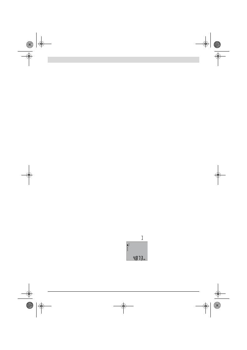
124
| Български
2 609 140 773 | (4.12.12)
Bosch Power Tools
Работа с уреда
Пускане в експлоатация
Не оставяйте уреда включен без надзор; след като
приключите работа, го изключвайте.
Други лица мо-
гат да бъдат заслепени от лазерния лъч.
Предпазвайте измервателния прибор от овлажнява-
не и директно попадане на слънчеви лъчи.
Не излагайте измервателния уред на екстремни
температури или резки температурни промени.
На-
пр. не го оставяйте продължително време в автомобил.
При големи температурни разлики оставяйте измерва-
телният уред да се темперира, преди да го включите.
При екстремни температури или големи температурни
разлики точността на измервателния уред може да се
влоши.
Избягвайте силни удари върху измервателния уред.
След силни външни механични въздействия трябва да
извършите проверка на точността на измервателния
уред, преди да продължите да го използвате (вижте
«Проверка на точността на измерване на дължини»,
страница 126).
Включване и изключване
За
включване
на измервателния уред имате следните
възможности:
– Натискане на бутона за включване/изключване
4
: из-
мервателният уред се включва в режим Измерване на
дължини. Лазерният лъч не се включва.
– Натиснете бутона Измерване
2
: измервателният уред и
лазерът се включват. Измервателният уред е в режим
измерване на дължини.
Не насочвайте лазерния лъч към хора или животни;
не гледайте срещу лазерния лъч, също и от голямо
разстояние.
За
изключване
на измервателния уред натиснете продъл-
жително бутона за включвне/изключване
4
.
Ако в продължение на прибл. 5 min не бъде натиснат бутон
на измервателния уред, за предпазване на батериите от
изтощаване измервателният уред се изключва автоматич-
но.
Измерване
След включване чрез натискане на бутона Измерване
2
измервателният уред винаги се включва в режим на из-
мерване на дължини. Можете да го превключите в други
режими на измерване чрез натискане на съответните
функционални бутони (вижте «Режими на измерване»,
страница 124).
След включване за отправна равнина автоматично се ус-
тановява задният ръб на измервателния уред. Можете да
смените отправната равнина чрез натискане на бутона
«Отправна равнина»
6
(вижте «Избор на отправна равни-
на», страница 124).
Допрете избраната за отправна (начална) страна на из-
мервателния уред до началната точка на измерването (на-
пр. стена).
За включване на лазерния лъч натиснете краткотрайно бу-
тона «измерване»
2
.
Не насочвайте лазерния лъч към хора или животни;
не гледайте срещу лазерния лъч, също и от голямо
разстояние.
Насочете лазерния лъч към целевата повърхност. За стар-
тиране на измерването натиснете отново бутона
2
кратко-
трайно.
В режим «непрекъснато измерване» измерването започва
веднага след включване на измервателния уред.
Обикновено измерената стойност се появява в рамките на
0,5 s и не по-късно от 4 s. Продължителността на измерва-
нето зависи от разстоянието, светлинните условия и отра-
зяващата способност на повърхността, до която се мери.
След завършване на измерването лазерът се изключва ав-
томатично.
Ако прибл. 20 s след насочване на лъча не бъде извърше-
но измерване, за предпазване на батериите лазерният лъч
се изключва автоматично.
Избор на отправна равнина (вижте фиг. А)
За измерването можете да избирате между три различни
начални равнини:
– задния ръб на измервателния уред (напр. при допира-
не до стена),
– предния ръб на измервателния уред (напр. при измер-
ване от ръба на маса),
– центъра на резбовия отвор
14
(напр. при измерване
със статив).
За избор на отправна равнина натиснете бутона
6
некол-
кократно, докато на дисплея бъде изобразен символа за
желаната отправна равнина. След включване на измерва-
телния уред отправна равнина е винаги задният ръб.
Осветление на дисплея
Осветлението на дисплея се включва автоматично в зави-
симост от околната осветеност. Ако известно време след
включване на осветлението на дисплея не бъде натиснат
бутон, за предпазване на батериите то се изключва.
Режими на измерване
Обикновено измерване на дължини (вижте фиг. В)
За измерване на дължини натиснете неколкократно буто-
на
9
, докато на дисплея се появи символът за измерване
на дължини .
За включване на лазерния лъч и за из-
мерване натиснете еднократно кратко-
трайно бутона Измерване
2
.
Измерената стойност се изобразява на
реда за резултата
b
.
При неколкократни последователни измервания на дъл-
жини резултатите на последните измервания се показват
на редовете за измерени стойности
a
.
OBJ_BUCH-1444-004.book Page 124 Tuesday, December 4, 2012 1:47 PM
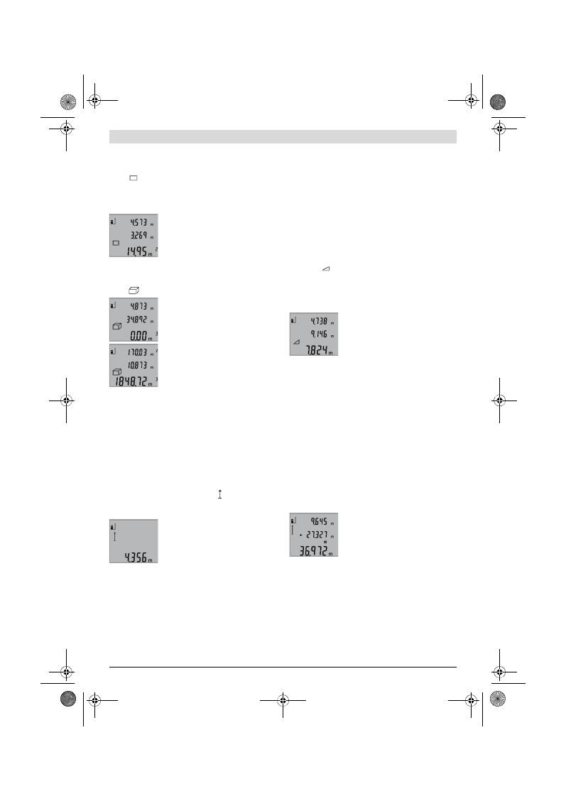
Български |
125
Bosch Power Tools
2 609 140 773 | (4.12.12)
Измерване на площ (вижте фиг. C)
За измерване на площи натиснете неколкократно бутона
3
, докато на дисплея се появи символът за измерване на
площи .
След това измерете последователно дължината и широчи-
ната, така, както измервате дължина. Лазерният лъч оста-
ва включен между двете измервания.
След приключване на второто измер-
ване площта се изчислява автоматично
и се изобразява на реда за резултата
b
.
Отделните измерени стойности се изо-
бразяват на редовете
a
.
Измерване на обем (вижте фиг. D)
За измерване на обеми натиснете неколкократно бутона
3
, докато на дисплея се появи символът за измерване на
обеми .
След това измерете последователно
дължината, широчината и височината,
така, както измервате дължина. Лазер-
ният лъч остава включен между измер-
ванията.
След приключване на третото измерва-
не обемът се изчислява автоматично и
се изобразява на реда за резултата
b
.
Отделните измерени стойности се изо-
бразяват на редовете
a
.
Стойности над 999999 m
3
не могат да бъдат изобразени,
на дисплея се появява
«ERROR»
. Разделете измервания
обем на части, които можете да измерите поотделно и
след това да съберете.
Непрекъснато измерване (вижте фиг. Е)
При непрекъснато измерване измервателният уред може
да бъде преместван спрямо целевата точка, като измере-
ната стойност се актуализира всеки 0,5 s. Например мо-
жете да се отдалечите от стена на желаното разстояние, те-
кущото разстояние се вижда непрекъснато.
За режим на непрекъснато измерване натиснете бутона
9
,
докато на дисплея се появи символът за непрекъснато
измерване. За стартиране на измерването натиснете буто-
на Измерване
2
.
Актуалната измерена стойност се изо-
бразява на реда за резултата
b
.
С натискане на бутона
2
прекратявате
непрекъснатото измерване. Последно
измерената стойност остава изобразе-
на на реда
b
. Повторно натискане на бу-
тона Измерване
2
стартира непрекъснатото измерване от-
начало.
Непрекъснатото измерване се изключва автоматично
след 5 min. Последно измерената стойност остава на реда
за резултата
b
.
Индиректно измерване на височина / Еднократно из-
мерване по теоремата на Питагор (вижте фигура F)
Индиректното измерване на височина служи за определя-
не на разстояния, които не могат да бъдат измерени непо-
средствено, напр. защото по пътя на лъча има препятствие
или защото в крайната точка няма отразяваща повърх-
ност. Точни резултати се постигат само ако при съответно-
то измерване се спазва стриктно прав ъгъл (теорема на
Питагор).
Внимавайте началната точка на измерването (напр. зад-
ния ръб на измервателния уред) да остане непроменена
при всички единични измервания в рамките на цялостно-
то измерване.
Между отделните измервания лазерният лъч остава вклю-
чен.
Натиснете неколкократно бутона
3
докато на дисплея се
появи символът за обикновено измерване по теоремата
на Питагор .
Измерете отсечките
«1»
и
«2»
в посочената последовател-
ност, както обикновено измервате дължини. При това вни-
мавайте ъгълът между отсечката
«1»
и търсената отсечка
«X»
да е прав.
След приключване на последното из-
мерване резултатът за търсената отсеч-
ка
«X»
се появява на реда за резултати
b
. Стойностите за отделните измерва-
ния са изписани на редовете
a
.
Изтриване на измерени стойности
Чрез краткотрайно натискане на бутона
4
можете да
изтриете последно измерената стойност във всички режи-
ми на измерване. Чрез многократно краткотрайно натис-
кане на бутона се изтриват в обратна последователност из-
мерените преди това стойности.
Събиране на измерени стойности
За да събирате измерени стойности, първо извършете не-
обходимото измерване. След това натиснете бутона
«Плюс»
8
. За потвърждение на дисплея се изобразява
символът
«+»
.
За да събирате обеми или площи, след първото завършено
измерване натиснете бутона «Плюс»
8
. За потвърждение
на дисплея вляво от символа за обем/площ се изобразява
символът
«+»
.
След това извършете второто измерване.
За получаване на резултата от събира-
нето натиснете още веднъж бутона
«Плюс»
8
. Събираемите се изобразяват
на редовете за измерени стойности
a
,
сборът – на реда за резултати
b
.
След изчисляване на сумата към нея могат да бъдат доба-
вени други измерени стойности, ако преди съответното
измерване бъден натискан бутонът «Плюс»
8
.
Указания за събиране:
– Не е възможно смесеното събиране на дължини, площи
и обеми. Ако напр. опитате да съберете дължина с
площ, при натискане на бутона «Плюс»
8
на дисплея за
кратко се появява надписът
«ERROR»
(Грешка). След
това измервателният уред се връща в последно използ-
вания режим на измерване.
OBJ_BUCH-1444-004.book Page 125 Tuesday, December 4, 2012 1:47 PM
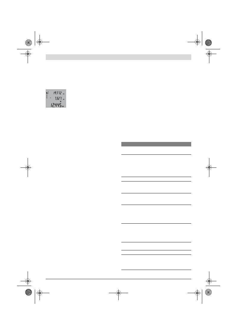
126
| Български
2 609 140 773 | (4.12.12)
Bosch Power Tools
– Добавя се винаги резултатът от едно измерване (напр.
стойност на обем); при непрекъснато измерване се до-
бавя изписаната на реда за резултата
b
стойност.
Сумирането на отделни измерени стойности от редове-
те
a
стойност. Сумирането на отделни измерени стойно-
сти от редовете.
Изваждане на резултати от измерването
За изваждане на измерени стойности
натиснете бутона за изваждане
5
, за
потвърждение на дисплея се появява
символът
«–»
. Начинът на работа е
аналогичен на «Събиране на измерени
стойности».
Указания за работа
Общи указания
По време на измерване приемащата леща
12
и отворът за
изходящия лазерен лъч
11
не трябва да бъдат закривани.
По време на измерване уредът не трябва да бъде премест-
ван (с изключение на режима «Непрекъснато измерва-
не»). Затова по възможност допирайте измервателния
уред до неподвижна опорна повърхност.
Фактори, влияещи върху диапазона на измерване
Диапазонът на измерване зависи от светлинните условия
и отражателните свойства на повърхността, до която се
измерва. За по-добра видимост на лазерния лъч при рабо-
та на открито и при силна слънчева светлина използвайте
специалните очила
19
(не са включени в окомплектовка-
та) и отразяваща мерителна плочка
20
(не е включена в
окомплектовката), или засенчете повърхността, до която
измервате.
Фактори, влияещи върху точността на измерването
Въз основа на ползваните при измерването физически
ефекти не могат да бъдат изключени възникващи грешки
при измерването до различни повърхности. В това число
влизат:
– прозрачни повърхности (напр. стъкло, вода),
– отразяващи повърхности (напр. полирани метални
предмети, стъкло),
– порести повърхности (напр. изолационни материали),
– повърхности с грапава структура (напр. груба мазилка,
естествен камък).
При необходимост при измерване до такива повърхности
използвайте отразяваща мерителна плочка
20
(не е вклю-
чена в окомплектовката).
Освен това грешни показания могат да се получат при из-
мерване до повърхности, които са под ъгъл.
Точността на измерената стойност може да се повлияе съ-
що така от наличието на въздушни слоеве със силен гради-
ент на температурата или индиректни отражения.
Проверка на точността на измерване на дължини
Можете да проверите точността на измерване на дължини
по следния начин:
– Изберете отсечка с постоянна дължина между 1 и 10 m,
която Ви е известна с достатъчна точност (напр. широ-
чината на стая, височина на врата). Измерваната отсеч-
ка трябва да е в затворено помещение, повърхността на
точката, до която измервате – гладка и отразяваща лъ-
чите добре.
– Измерете отсечката 10 пъти последователно.
Отклонението на единичните измервания от средната
стойност не трябва да надвишават ±2 mm. Запишете и за-
пазете измерените стойности, за да можете да сравните
точността на измервателния уред по-късно.
Работа със статив (допълнително приспособление)
Използването на статив е необходимо особено при измер-
ване на големи дължини. Като използвате отвора с резба
14
захванете уреда към плочката за бързо захващане на
статива
18
или обикновен статив за фотоапарати. Затегне-
те го с винта за застопоряване на плочката за бързо захва-
щане на статива.
Поставете съответно отправната равнина за измерване
със статив чрез натискане на бутона
6
(отправна равнина
резбови отвор).
Грешки
–
причини за възникване и начини за
отстраняването им
Причина
Отстраняване
Предупредителният символ за температура (f) мига,
не е възможно извършването на измервания
Измервателният уред е извън
допустимия температурен диа-
пазон за работа от – 10 °C до
+50 °C (в режим на не-
прекъснато измерване до
+40 °C).
Изчакайте, докато тем-
пературата на
измервателния уред
достигне допустимия
работен диапазон
Надпис «ERROR» на дисплея
Опит за събиране/изваждане на
стойности с различни мерни
единици
Събирайте/изваж-
дайте само стойности с
еднаква размерност
Ъгълът между лазерния лъч и це-
левата повърхност е твърде ос-
тър.
Увеличете ъгъла между
лазерния лъч и целева-
та повърхност
Целевата повърхност отразява
твърде силно (напр. огледало),
респ. твърде слабо (напр. черен
плат), или околната светлина е
твърде силна.
Използвайте отража-
телната плочка
20
(до-
пълнително приспосо-
бление)
Изходящият отвор за лазерния
лъч
11
респ. приемащата леща
12
са запотени (напр. в резултат
на рязка температурна промя-
на).
Избършете изходящия
отвор за лазерния лъч
11
респ. приемащата
леща
12
с мека кърпа
Изчислената стойност е по-голя-
ма от 999999 m/m
2
/m
3
.
Разделете изчисление-
то на отделни стъпки
Резултатът от измерването е недостоверен
Целевата повърхност не отразя-
ва по подходящ начин за
еднозначно измерване (напр.
водна повърхност, стъкло).
Покрийте целевата
повърхност
OBJ_BUCH-1444-004.book Page 126 Tuesday, December 4, 2012 1:47 PM
Srpski |
127
Bosch Power Tools
2 609 140 773 | (4.12.12)
Измервателният уред следи коректното
си функциониране при всяко измерване.
Ако бъде установен проблем, на дисплея
започва да мига показаният встрани сим-
вол. В такъв случай или в случай, че посо-
чените по-горе мерки не отстранят
възникналия проблем, занесете измервателния уред на
Вашия търговец или в оторизиран сервиз за електроин-
струменти на Бош.
Поддържане и сервиз
Поддържане и почистване
Съхранявайте и пренасяйте уреда само във включената в
окомплектовката предпазна чанта.
Поддържайте измервателния уред винаги чист.
Не потопявайте измервателния уред във вода или други
течности.
Избърсвайте замърсяванията с мека, леко навлажнена
кърпа. Не използвайте почистващи препарати или разтво-
рители.
Отнасяйте се специално към приемащата леща
12
със съ-
щото внимание, с което се отнасяте към очила или обектив
на фотоапарат.
Ако въпреки прецизното производство и внимателно из-
питване измервателният уред се повреди, ремонтът тряб-
ва да бъде извършен в оторизиран сервиз за електро-
инструменти на Бош. Не се опитвайте да отваряте измер-
вателния уред.
Моля, когато се обръщате към представителите на Бош с
въпроси и когато поръчвате резервни части, непременно
посочвайте 10-цифрения каталожен номер от табелката
на измервателния уред.
При необходимост от ремонт предоставяйте измервател-
ния уред в чантата
17
.
Сервиз и технически съвети
Отговори на въпросите си относно ремонта и поддръжката
на Вашия продукт можете да получите от нашия сервизен
отдел. Монтажни чертежи и информация за резервни час-
ти можете да намерите също на адрес:
www.bosch-pt.com
Екипът на Бош за технически съвети и приложения ще от-
говори с удоволствие на въпросите Ви относно нашите
продукти и допълнителните приспособления за тях.
Роберт Бош EООД – България
Бош Сервиз Център
Гаранционни и извънгаранционни ремонти
бyл. Черни връx 51-Б
FPI Бизнес център 1407
1907 София
Тел.: (02) 9601061
Тел.: (02) 9601079
Факс: (02) 9625302
www.bosch.bg
Бракуване
Измервателния уред, допълнителните приспособления и
опаковките трябва да бъдат подложени на екологична пре-
работка за усвояване на съдържащите се в тях суровини.
Не изхвърляйте измервателни уреди и акумулаторни бате-
рии/батерии при битовите отпадъци!
Само за страни от ЕС:
Съгласно Европейска директива
2002/96/EО измервателни уреди и съ-
гласно Европейска директива
2006/66/ЕО акумулаторни или обикно-
вени батерии, които не могат да се из-
ползват повече, трябва да се събират от-
делно и да бъдат подлагани на подходяща преработка за
оползотворяване на съдържащите се в тях суровини.
Правата за изменения запазени.
Srpski
Uputstva o sigurnosti
Sva uputstva se moraju čitati i pazite na
njih, da bi sa mernim alatom radili bez
opasnosti i sigurno. Neka Vam tablice sa
upozorenjem na mernom alatu budu uvek
čitljive. ČUVAJTE OVA UPUTSTVA DOBRO.
Oprez – ako se koriste drugi uredjaji za rad ili
podešavanje od onih koji su ovde navedeni, ili izvode
drugi postupci, može ovo voditi eksplozijama sa
zračenjem.
Изходящият отвор за лазерния
лъч
11
респ. приемащата леща
12
са покрити.
Освободете изходящия
отвор за лазерния лъч
11
респ. приемащата
леща
12
Избрана е грешна отправна рав-
нина
Изберете отправна
равнина, подходяща за
извършваното измер-
ване
Препятствие по пътя на лазер-
ния лъч
Цялата лазерна точка
трябва да попадне на
повърхността, до която
се измерва.
Изображението на дисплея не се променя или измер-
вателният уред реагира неадекватно на натискане на
бутон
Софтуерна грешка
Извадете батериите и,
след като ги поставите
отново, включете из-
мервателния уред.
Причина
Отстраняване
OBJ_BUCH-1444-004.book Page 127 Tuesday, December 4, 2012 1:47 PM

128
| Srpski
2 609 140 773 | (4.12.12)
Bosch Power Tools
Merni alat se isporučuje sa tablicom sa upozorenjem na
engleskom jeziku (obeleženo na prikazu mernog alata
na grafičkoj stranici sa brojem 15).
Prelepite engleski tekst tablice sa opomenom pre
prvog puštanja u rad sa isporučenom nalepnicom na
Vašem jeziku.
Ne upravljajte laserski zrak na osobe ili životinje i ne
gledajte sami u laserski zrak.
Ovaj merni alat proizvodi
lasersko zračenje klase lasera 2 prema IEC 60825-1. Na
taj način možete zaslepiti osobe.
Ne koristite laserske naočare za posmatranje kao
zaštitne naočare.
Laserske naočare za posmatranje služe
za bolje prepoznavanje laserskog zraka, one ne štite od
laserskog zračenja.
Ne upotrebljavajte laserske naočare za posmatranje
kao naočare za sunce ili u putnom saobraćaju.
Laserske
naočare za posmatranje ne pružaju punu UV zaštitu i
smanjuju opažanje boja.
Neka Vam merni alat popravlja stručno osoblje i samo
sa originalnim rezervnim delovima.
Time se
obezbedjuje, da sigurnost mernog alata ostaje sačuvana.
Ne dopu štaje deci korišćenje mernog alata sa laserom
bez nadzora.
Oni bi mogli nenamerno zaslepiti osoblje.
Ne radite sa mernim alatom u okolini gde postoji
opasnost od eksplozija, u kojoj se nalaze zapaljive
tečnosti, gasovi ili prašine.
U mernom alatu se mogu
proizvesti varnice, koje bi zapalite prašinu ili isparenja.
Opis proizvoda i rada
Molimo da otvorite preklopljenu stranicu sa prikazom mernog
alata, i ostavite ovu stranicu otvorenu dok čitate uputstvo za
rad.
Upotreba koja odgovara svrsi
Merni alat je zamišljen za merenje udaljenosti, dužina, visina,
rastojanja i za izračunavanje površina i zapremina. Merni alat
je zamišljen za merenje u unutrašnjem i spoljnom području.
Tehnički podaci
Digitalni laserski merač rastojanja
GLM 50
Professional
Broj predmeta
3 601 K72 2..
Merno područje
0,05 –50 m
A)
Merna tačnost (tipično)
±1,5 mm
B)
Najmanja jedinica pokazivača
1 mm
Radna temperatura
–10 °C...+50 °C
C)
Temperatura skladišta
–20 °C...+70 °C
Relativna vlaga vazduha max.
90 %
Klasa lasera
2
Tip lasera
635 nm, <1 mW
Presek laserskog zraka (pri 25 °C) cca.
– na 10 m udaljenosti
– na 50 m udaljenosti
6 mm
35 mm
Automatika za isključivanje posle oko
– Laser
– Merni alat (bez merenja)
20 s
5 min
Baterije
Akumulatorske ćelije
2 x 1,5 V LR03 (AAA)
2 x 1,2 V HR03 (AAA)
Životni vek baterije ca.
– Pojedinačna merenja
– Trajno mrenje
10000
D)
2,5 h
D)
Težina prema EPTA-Procedure 01/2003
0,14 kg
Dimenzije
53 x 114 x 30 mm
Vrsta zaštite
IP 54 (zaštićeno od prašine i prskanja vode)
OBJ_BUCH-1444-004.book Page 128 Tuesday, December 4, 2012 1:47 PM
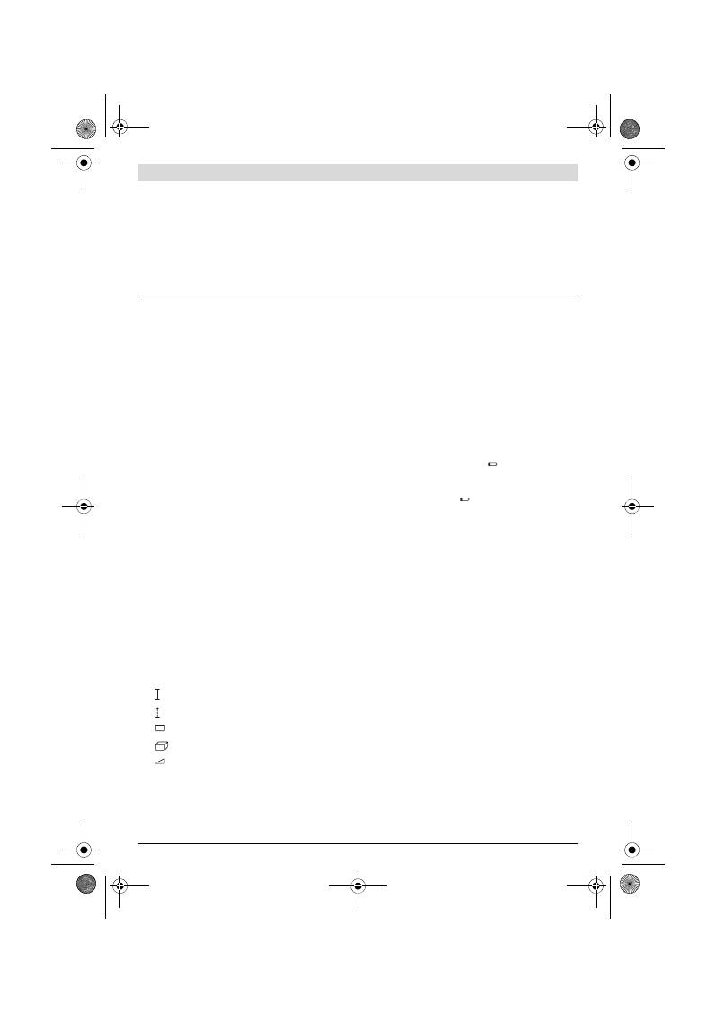
Srpski |
129
Bosch Power Tools
2 609 140 773 | (4.12.12)
Komponente sa slike
Označavanje brojevima komponenti sa slike odnosi se na
prikaz mernog alata na grafičkoj stranici.
1
Displej
2
Taster za merenje
3
Taster za površinsko, zapreminsko i indirektno merenje
visina (pitagora)
4
Taster za brisanje / taster za uključivanje-isključivanje **
5
Minus taster
6
Taster za biranje referentne ravni
7
Prihvat kaiša za nošenje
8
Plus taster
9
Taster za merenje dužina – trajno merenje
10
Poklopac prostora za bateriju
11
Izlaz laserskog zračenja
12
Prijemno sočivo
13
Serijski broj
14
1/4"-navoj
15
Laserska tablica sa opomenom
16
Blokiranje poklopca prostora za bateriju
17
Zaštitna torba
18
Stativ*
19
Laserske naočare za gledanje*
20
Laserska ciljna ploča*
* Pribor sa slike ili koji je opisan ne spada u standardni obim
isporuka.
** Taster držati pritisnut radi pozivanja proširenih funkcija.
Elementi za pokazivanje
a
Redovi merne vrednosti
b
Red sa rezultatom
c
Merne funkcije
d
Laser uključen
e
Referentna ravan merenja
f
Opomena za temperaturu
g
Opomena za bateriju
h
Pokazivač greške
„ERROR“
Montaža
Ubacivanje baterije/promena
Za rad mernog alata se preporučuje upotreba alkalnih
mangan-baterija ili akumulatora.
Sa 1,2-V-je moguće manje merenja nego sa 1,5-V-baterijom.
Za otvaranje poklopca prostora za baterije
10
pritisnite
blokadu
16
i izvadite poklopac prostora za bateriju. Ubacite
nove baterije odnosno akumulator. Pazite pritom na prave
polove prema prikazu na unutrašnjoj stranici prostora za
bateriju.
Pazite kod ubacivanja baterija odnosno akumulatora na pravi
pol prema slici u prostoru za baterije.
Ako se pojavljuje simbol za bateriju
prvo na displeju, onda
jemoguće još najmanje 100 pojedinačnih merenja. Funkcija
trajnog merenja je deaktivirana.
Ako treperi simbol baterije
, moraju se promeniti baterije
odnosno akumulatorske ćelije. Merenja više nisu moguća.
Menjajte uvek sve baterije odnosno akumulatore
istovremeno. Upotrebljavajte samo baterije ili akumulatore
jednog proizvodjača i sa istim kapacitetom.
Izvadite baterije odnosno akumulatore iz mernog alata,
kada duže vremena ne koristite.
Baterije i akumulatori
mogu kod dužeg čuvanja korodirati i same se isprazniti.
Rad
Puštanje u rad
Ne ostavljajte slučajno uključen merni alat i isključite
merni alat posle upotrebe.
Druge osobe bi mogle da budu
zaslepljene od laserskog zraka.
Čuvajte merni alat od vlage i direktnog sunčevog
zračenja.
Ne izlažite merni alat ekstremnim temperaturama ili
temperaturnim kolebanjima.
Ne ostavljajte ga na primer
u autu duže vreme. Pustite merni alat pri većim
temperaturnim kolebanjima da se prvo temperira, pre
nego ga pustite u rad. Pri ekstremnim temperaturama ili
temperaturnim kolebanjima može se oštetiti preciznost
mernog alata.
Izbegavajte jake udarce ili padove mernog alata.
Posle
jakih spoljnih uticaja na merni alat trebali bi uvek pre daljeg
rada izvršiti kontrolu tačnosti (pogledajte „Kontrola
tačnosti pri merenju rastojanja“, stranicu 131).
A) Domet je veći ukoliko se lasersko svetlo bolje odbija od površine cilja (rasipajuće, bez odsjaja) i ukoliko je laserska tačka svetlija prema svetlosti
okoline (Unutrašnje prostorije, sumrak). Pri nepovoljnim uslovima (na primer merenje u spoljnom području sa jakim sunčevim zračenjem) može biti
potrebno, upotrebiti tablicu sa ciljem.
B) Pri merenju od zadnje ivice mernog alata. Pri nepovoljnim uslovima kao na primer jačeg sunčevog zračenja ili loše reflektujuće površine iznosi
maksimalno odstupanje
±
10 mm na 50 m. Pri nepovoljnim uslovima mora se računati sa uticajem od
±
0,05 mm/m.
C) U funkciji trajnog merenja iznosi maks. radna temperatura +40
°C
.
D) Sa 1,2-V-akumulatorskim ćelijama moguće je manje merenja nego sa 1,5-V-baterije. Navedeno trajanje rada baterija odnosi se na merenja bez
osvetlenja displeja.
Za jasniju identifikaciju Vašeg mernog alata služi serijski broj
13
na tipskoj tablici.
Dužinsko merenje
Trajno merenje
Površinsko merenje
Zapreminsko merenje
Jednostavno merenje po pitagori
OBJ_BUCH-1444-004.book Page 129 Tuesday, December 4, 2012 1:47 PM
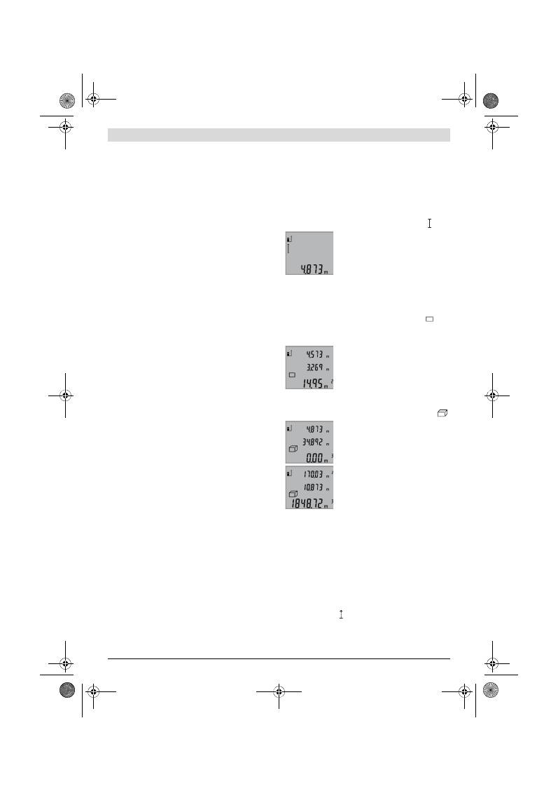
130
| Srpski
2 609 140 773 | (4.12.12)
Bosch Power Tools
Uključivanje-isključivanje
Za
uključivanje
mernog alata imate sledeće mogućnosti:
– Pritisnite taster za uključivanje-isključivanje
4
: Merni alat
se uključuje i nalazi se u funkciji merenja po dužini. Laser se
ne uključuje.
– Pritisnite na taster merenje
2
: Merni alat i laser se
uključuju. Merni alat se nalazi u funkciji merenja po dužini.
Ne usmeravajte laserski zrak na osobe ili životinje i ne
gledajte u laserski zrak čak ni sa daljeg odstojanja.
Za
isključivanje
mernog alata pritisnite dugo na taster za
uključivanje-isključivanje
4
.
Ako se ca. 5 min dugo ne pritisne nijedan taster na mernom
alatu, onda se merni alat radi čuvanja baterija automatski
isključuje.
Radnja merenja
Posle uključivanja pritiskivanjem na taster merenje
2
nalazi se
merni alatg uvek u funkciji merenja po dužini. Druge merne
funkcije možete podesiti pritiskivanjem tastera za funkcije
(pogledajte „Merne funkcije“, stranu 130).
Kao referentna ravan za merenje izabrana je posle
uključivanja zadnja ivica mernog alata. Pritiskivanjem tastera
referentne ravni
6
možete menjati referentnu ravan
(pogledajte „Biranje osnovne ravni“, stranicu 130).
Postavite merni alat sa izabranom osnovnom ravni na željenu
tačku za kretanje merenja (ma. primer zid).
Pritisnite za uključivanje laserskog zraka na kratko taster za
merenje
2
.
Ne usmeravajte laserski zrak na osobe ili životinje i ne
gledajte u laserski zrak čak ni sa daljeg odstojanja.
Vizirajte sa laserskim zrakom površinu cilja. Pritisnite za
biranje merenja ponovo na kratko taster za merenje
2
.
U funkciji trajnog merenja počinje merenje odmah posle
uključivanja funkcije.
Merna vrednost se tipično pojavljuje u roku od 0,5 s i
najkasnije posle 4 s. Trajanje merenja zavisi od udaljenosti,
svetlosnih uslova i refleksnih osobina ciljne površine. Po
završavanju merenja laserski zrak se automatski isključuje.
Ako se ca. 20 s posle viziranja ne izvrši merenje, automatski
se isključuje laserski zrak radi čuvanja baterija.
Biranje osnovne ravni (pogledajte sliku A)
Za merenje možete izabrati tri različite referentne ravni:
– zadnja ivica mernog alata (na primer kod postavljanja na
zidove),
– prednje ivice mernog alata (na primer kod merenja sa ivice
stola),
– sredine navoja
14
(na primer za merenja sa stativom).
Pritiskajte za biranje referentne ravni taster
6
toliko često, sve
dok se na displeju ne pokaže željena referentna ravan. Posle
svakog uključivanja mernog alata je zadnja ivica mernog alata
prethodno podešena kao referentna ravan.
Osvetlenje displeja
Osvetljenje displeja se zavisno od osvetlenja okoline
automatski pali. Ako posle uključivanja osvetlenja displeja ne
bude pritisaka na tastere, isključuje se baterija radi čuvanja.
Merne funkcije
Jednostruko merenje dužine (pogledajte sliku B)
Pritiskajte za merenja po dužini taster
9
toliko puta, sve dok
se na displeju ne pojavi pokazivač za merenje dužine .
Pritisnite za uključivanje lasera i za
merenje uvek i samo jednom na kratko
taster merenje
2
.
Merna vrednost se pokazuje u redu za
rezultat
b
.
Kod više dužinskih merenja jedno za drugim pokazuju se
rezultati poslednjih merenja u redovima za mernu vrednost
a
.
Merenje površina (pogledajte sliku C)
Pritiskajte za merenje površina taster
3
toliko puta, sve dok se
na displeju ne pojavi pokazivač za merenje površina
.
Merite na kraju dužinu i širinu jedno za drugim kao pri merenju
dužina. Izmedju oba merenja ostaje laserski zrak uključen.
Posle završetka drugog merenja se
površina automatski izračunava i
prikazuje red sa rezultatom
b
. Pojedi-
načne merne vrednosti stoje u redovima
za mernu vrednost
a
.
Merenje zapremine (pogledajte sliku D)
Pritiskajte za merenje zapremine taster
3
toliko puta, sve dok
se na displeju ne pojavi pokazivač za merenje zapremine
.
Merite na kraju jedno za drugim dužinu,
širinu i visinu kao kod merenja dužine.
Izmedju tri merenja ostaje uključen
laserski zrak.
Posle završavanja trećeg merenja
izračunava se zapremina automatski i pri-
kazuje u redu za rezultat
b
. Pojedinačne
vrednosti stoje u redovima za mernu
vrednost
a
.
Vrednosti iznad 999999 m
3
ne mogu se prikazati, na displeju
se pojavljuje:
„ERROR“
. Podelite zapreminu koju treba meriti
u pojedinačna merenja, čije vrednosti izračunajte odvojeno i
onda spojite.
Trajno merenje (pogledajte sliku E)
Kod trajnog merenja može se merni alat relativno pokretati
prema cilju, pričem se aktuelizuje merna vrednost ca. svakih
0,5 s. Možete se udaljiti na primer od nekog zida pa do
željenog rastojanja, aktuelno odstojanje je uvek moguće
očitati.
Za trajno merenje pritiskajte taster
9
, sve dok se na displeju
ne pojavi pokazivač za trajno merenje. Pritisnite za start
trajnog merenja taster merenje
2
.
OBJ_BUCH-1444-004.book Page 130 Tuesday, December 4, 2012 1:47 PM
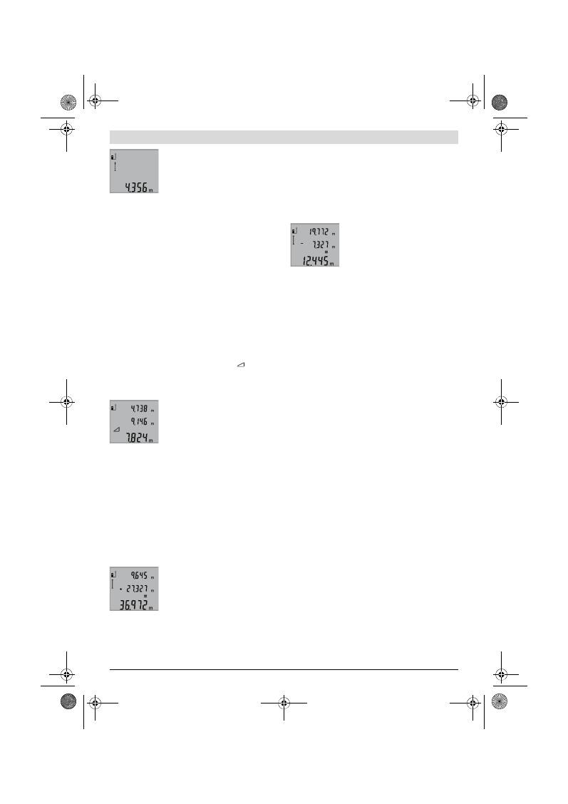
Srpski |
131
Bosch Power Tools
2 609 140 773 | (4.12.12)
Pokazuje se aktuelna vrednost u redu za
rezultat
b
.
Pritiskivajući taster merenje
2
završavate
trajno merenje. Poslednja merna
vrednost se prikazuje u redu sa
rezultatom
b
. Ponovnim pritiskivanjem
tastera merenje
2
startuje ponovo trajno merenje.
Trajno merenje se automatskii isključuje posle 5 min.
Poslednja vrednost merenja ostaje prikazana u redu za
rezultat
b
.
Indirektno visinsko merenje / Jednostavno merenje po
pitagori (pogledajte sliku F)
Indirektno merenje visine služi za dobijanje rastojanja, koja se
ne mogu direktno meriti, jer bi pravac zraka omela neka
smetnja ili nema na raspolaganju ciljne površine kao
reflektora. Korektni rezultati se samo onda postižu, kada se
kod odgovarajućeg merenja uvek održava tačno traženi desni
ugao (Pitagorina teorema).
Pazite na to, da referentna tačka merenja (na. primer zadnja
ivica mernog alata) kod svih pojedinačnih merenja ostaje
tačno na istom mestu u roku radnje merenja.
Izmedju pojedinačnih merenja ostaje laserski zrak uključen.
Pritiskajte taster
3
tako često, dok se na displeju ne pojavi
pokazivač za jednostavno merenje po Pitagori
.
Merenje kao kod merenja dužine linija
„1“
i
„2“
ovim
redosledom. Pazite na to, da izmedju linije
„1“
i tražene linije
„X“
bude pravi ugao.
Po završetku poslednjeg merenja
pokazuje se rezultat za traženu liniju
„X“
u
redu za rezultat
b
. Pojedinačne merne
vrednosti stoje u redovima mernih
vrednosti
a
.
Brisanje mernih vrednosti
Kratkim pritiskivanjem tastera
4
možete izbrisati u svim mer-
nim funkcijama poslednju iznadjenu vrednost pojedinačnog
merenja. Višestrukim kratkim pritiskivanjem tastera brišu se
pojedinačne merne vrednosti obrnutim redosledom.
Sabiranje mernih vrednosti
Da bi sabrali merne vrednosti, izvedite prvo željeno merenje.
Pritisnite onda plus taster
8
. Na displeju se pojavljuje radi
potvrdjivanja
„+“
.
Da bi sabirali zapremine ili površine,pritisnite posle prvog
završenog merenja plus taster
8
. Na displeju se pojavljuje radi
potvrdjivanja
„+“
levo od simbola zapremine-/površine.
Izvedite onda drugo merenje.
Pritisnite radi vidjenja zbira oba merenja
još jednom plus taster
8
. Izračunavanje se
pokazuje u redovima za mernu vrednost
a
, zbir stoji u redu za rezultat
b
.
Posle izračunavanja zbira možete sabirati
na ovaj rezultat dalje merne vrednosti,
ako se pre merenja uvek pritisne plus taster
8
.
Uputstvo za sabiranje:
– Dužinske, površinske i zapreminske vrednosti se ne mogu
mešano sabirati. Ako se sabiraju na primer dužinska i
površinska vrednost, pojaviće se pri pritiskivanju plus
tastera
8
na kratko
„ERROR“
na displeju. Potom menja
merni alat u poslednju aktivnu mernu funkciju.
– Uvek se sabira rezultat merenja (na primer zapreminska
vrednost), kod trajnog merenja merna vrednost prikazana
u redu za rezultat
b
. Sabiranje vrednosti pojedinačnih
merenja iz redova mernih vrednosti
a
nije moguće.
Oduzimanje merne vrednosti
Za oduzimanje mernijh vrednosti
pritisnite minus taster
5
, na displeju se
pojavljuje radi potvrdjivanja
„–“
. Dalji
postupak je analogan „Sabiranje mernih
vrednosti“.
Uputstva za rad
Opšta uputstva
Prijemno sočivo
12
i izlaz laserskog zraka
11
ne smeju biti
pokriveni pri merenju.
Merni alat se za vreme merenja nesme pokretati (sa izuzetkom
funkcije trajnog merenja). Stoga postavite merni alat što je
više moguće na neku čvrstu nepokretnu ili površinu za
postavljanje.
Uticaji na merno područje
Merno područje zavisi od svetlosnih uslova i osobina
refleksije ciljne površine. Koristite radi bolje vidljivosti
laserskog zraka pri radu u spoljnim površinama i pri jakom
sunčevom zračenju laserske naočare
19
(pribor) i lasersku
tablicu sa ciljem
20
(pribor), ili isključite ciljnu površinu.
Uticaji na merni rezultat
Na osnovu fizikalnih efekata ne može se isključiti, da pri
merenju na različitim površinama dodje do pogrešnih
merenja. U njih se ubrajaju:
– transparentne površine (na primer staklo, voda),
– površine sa odsjajem (na primer polirani metal, staklo),
– porozne površine (na primer materijali za prigušivanje),
– strukturne površine (na primer hrapavi malter, prirodni
kamen).
Koristite u datom slučaju na ovim površinama lasersku tablicu
sa ciljem
20
(pribor).
Pogrešna merenja su osim toga moguća na koso aviziranu
površinu cilja.
Isto tako mogu slojevi vazduha sa raznim temperaturama ili
indirektno prihvaćene refleksije da utiču na mernu vrednost.
Kontrola tačnosti pri merenju rastojanja
Možete kontrolisati tačnost merenja rastojanja na sledeći
način:
– Izaberite trajno nepromenljivu mernu trasu od ca. 1 do
10 m dužine, čija je dužina Vama tačno poznata (na primer
širina prostorije, otvor za vrata). Merna trasa mora biti u
unutrašnjem prostoru, ciljna površina merenja ravna i
dobro reflektujuća.
– Merite trasu 10-puta jedno za drugim.
Odstupanje pojedinačnih merenja od srednje vrednosti sme
iznositi maksimalno ±2 mm. Zapišite merenja, da bi mogli
porediti nekada kasnije tačnost.
OBJ_BUCH-1444-004.book Page 131 Tuesday, December 4, 2012 1:47 PM
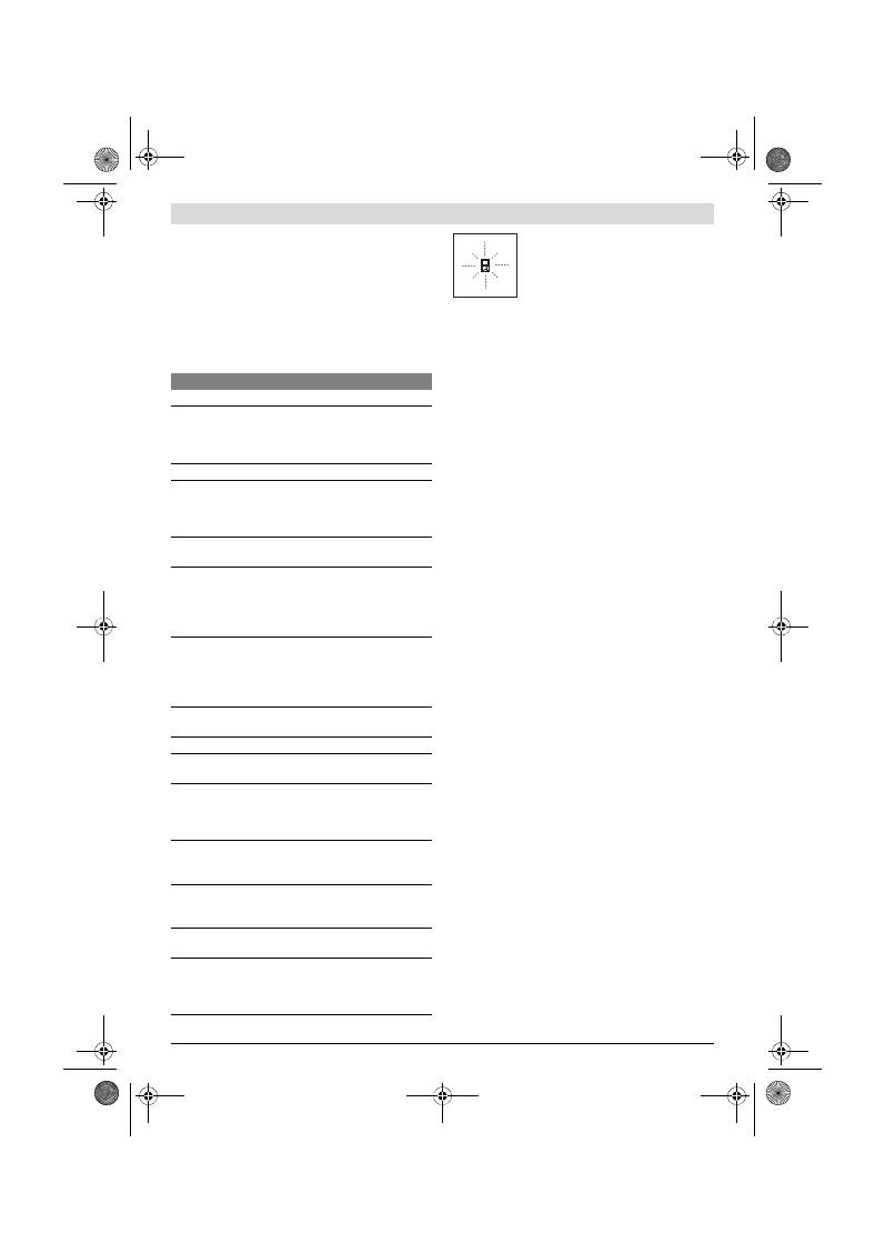
132
| Srpski
2 609 140 773 | (4.12.12)
Bosch Power Tools
Radovi sa stativom (pribor)
Korišćenje stativa je posebno potrebna pri većim
rastojanjima. Stavite merni alat sa 1/4"-navoja
14
na brzo
promenljivu ploču stativa
18
ili neki foto stativ uobičajen u
trgovini. Čvrsto uvrnite sa zavrtnjem za fiksiranje brzo
promenljive ploče.
Podesite prema tome osnovnu ravan za merenje sa stativom
pritiskujući taster
6
(navoj osnovne ravni).
Greške – uzroci i pomoć
Merni alat kontroliše ispravno
funkcionisanje pri svakom merenju. Ako se
utvrdi kvar, treperi na displeju samo simbol
koji stoji pored. U ovom slučaju ili ako gore
navedene mere pomoći ne mogu da uklone
nedostatak, odnesite merni alat preko
Vašeg trgovca Bosch-servisu.
Održavanje i servis
Održavanje i čišćenje
Čuvajte i transportujte merni pribor samo u isporučenoj
zaštitnoj futroli.
Držite merni alat uvek čist.
Ne uranjajte merni alat u vodu ili druge tečnosti.
Brišite zaprljanja sa vlažnom, mekom krpom. Ne
upotrebljavajte nikakva sredstva za čišćenje ili rastvarače.
Održavajte posebno prijemno sočivo
12
sa istom pažnjom,
kao što morate da se ophodite sa naočarima ili sočivom foto
aparata.
Ako bi merni alat i pored brižljivog postupka proizvodnje i
kontrole nekada otkazao, popravku mora vršiti neki stručni
servis za Bosch-električne alate. Ne otvarajte merni alat sami.
Kod svih pitanja i naručivanja rezervnih delova navedite
neizostavno broj predmeta prema tipskoj tablici mernog alata
koja ima 10 brojčanih mesta.
U slučaju popravke šaljite merni alat u zaštitnoj torbi
17
.
Servisna služba i savetovanje o upotrebi
Servisna služba odgovoriće na vaša pitanja o popravcima i
održavanju vašeg proizvoda i o rezervnim delovima. Uvećane
crteže i informacije o rezervnim delovima možete naći na
našoj adresi:
www.bosch-pt.com
Bosch tim za savetovanje o upotrebi će vam rado pomoći ako
imate pitanja o našim proizvodima i priboru.
Srpski
Bosch-Service
Dimitrija Tucovića 59
11000 Beograd
Tel.: (011) 2448546
Fax: (011) 2416293
E-Mail: asboschz@EUnet.yu
Uklanjanje djubreta
Merni alati, pribor i pakovanja treba da se dovoze na
regeneraciju koja odgovara zaštiti čovekove okoline.
Ne bacajte merne alate i akumulatore (baterije u kućno
djubre).
Uzrok
Pomoć
Temperaturna opomena (f) treperi, merenje nije moguće
Merni alat je izvan radne
temperature od – 10 °C do
+50 °C (u funkciji trajnog merenja
do +40 °C).
Sačekati, dok merni alat
ne dostigne radnu
temperaturu
Pokazivač „ERROR“ na displeju
Sabiranje/oduzivanje mernih
vrednosti sa različitim mernim
jedinicama
Sabirajte/oduzimajte
samo merne vrednosti
sa istim mernim jedini-
cama
Ugao izmedju laserskog zraka i
cilja je suviše oštar.
Povećati ugao izmedju
laserskog zraka i cilja
Površina cilja reflektuje prejako
(na primer ogledalo) odnosno
preslabo (na primer crni
materijal), ili je svetlo okoline
prejako.
Koristite lasersku tablicu
sa ciljem
20
(pribor)
Izlaz laserskog zračenja
11
odnosno prijemnog sočiva
12
je
oznojeno (na primer usled brze
promene temperature).
Istrljajte na suvo sa
mekom krpom izlaz
laserskog zračenja
11
odnosno prijemno
sočivo
12
Izračunata vrednost je veća od
999999 m/m
2
/m
3
.
Izračunavanje podeliti
na medjuodeljke
Merni rezultat ne svetli
Površina cilja ne reflektuje jasno
(na primer voda, staklo).
Pokriti površinu cilja
Izlaz laserskog zračenja
11
odnosno prijemno sočivo
12
je
pokriveno.
Osloboditi izlaz laser-
skog zračenja
11
odnosno prijemno
sočivo
12
Pogrešno podešena referentna
ravan
Izabrati referentnu
ravan da odgovara
merenju
Smetnje u toku laserskog zraka
Laserska tačka mora da
leži kompletno na ciljnoj
površini.
Pokazivač ostaje nepromenjen ili merni alat reaguje
neočekivano na pritisak tastera
Greška u Software
Izvadite baterije i
startujte merni alat
posle ponovnog
ubacivanja
OBJ_BUCH-1444-004.book Page 132 Tuesday, December 4, 2012 1:47 PM
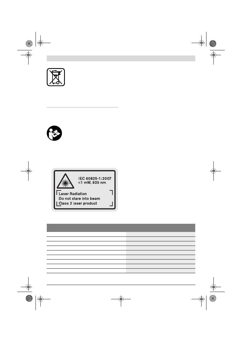
Slovensko |
133
Bosch Power Tools
2 609 140 773 | (4.12.12)
Samo za EU-zemlje:
Prema evropskoj smernici 2002/96/EG ne
moraju više neupotrebljivi merni alati a
prema evropskoj smernici 2006/66/EG ne
moraju više akumulatori/baterije u kvaru i
istrošeni da se odvojeno sakupljaju i odvoze
reciklaži koja odgovara zaštiti čovekove
sredine.
Zadržavamo pravo na promene.
Slovensko
Varnostna navodila
Da bi z merilnim orodjem delali brez nevar-
nosti in varno, morate prebrati in upošte-
vati vsa navodila. Opozorilne tablice nikoli
ne smejo biti nerazpoznavne. TA NAVODI-
LA DOBRO SHRANITE.
Bodite previdni – v primeru izvajanja opravil ali nasta-
vitev, ki niso opisana v teh navodilih, lahko pride do ne-
varnega izpostavljanja laserskemu sevanju.
Merilno orodje je dobavljeno z opozorilnim napisom v
angleščini (na slikovnem prikazu merilnega orodja na
strani z grafiko označen s številko 15).
Pred prvim zagonom prelepite angleški tekst opozoril-
ne table s priloženo nalepko v svojem jeziku.
Laserskega žarka ne usmerjajte na osebe ali živali in sa-
mi ne glejte v laserski žarek.
Merilno orodje ustvarja la-
sersko žarčenje laserskega razreda 2 v skladu z
IEC 60825-1. Z njim bi lahko zaslepili druge osebe.
Očal za vidnost laserskega žarka ne uporabljajte name-
sto zaščitnih očal.
Očala za vidnost laserskega žarka so
namenjena boljšemu razpoznavanju laserskega žarka, ven-
dar oči ne varujejo pred laserskim sevanjem.
Očal za vidnost laserskega žarka ne uporabljajte name-
sto sončnih očal oziroma med vožnjo v cestnem prome-
tu.
Očala za vidnost laserskega žarka ne zagotavljajo po-
polne UV-zaščite in zmanjšujejo sposobnost zaznavanja
barv.
Merilno orodje lahko popravlja samo kvalificirano stro-
kovno osebje z origialnimi nadomestnimi deli.
Na ta na-
čin bo ohranjena varnost merilnega orodja.
Otrokom ne dovolite, da bi brez nadzora uporabljali la-
sersko merilno orodje,
saj bi lahko nenamerno zaslepili
druge osebe.
Z merilnim orodjem ne smete delati v okolju, kjer je ne-
varnost eksplozije in kjer se nahajajo gorljive tekočine,
plini ali prah.
Merilno orodje lahko povzroči iskrenje, ki
lahko vname prah ali hlape.
Opis in zmogljivost izdelka
Prosimo odprite zloženo stran, kjer je prikazano merilno orod-
je in pustite to stran med branjem navodila za uporabo odpr-
to.
Uporaba v skladu z namenom
Ta naprava je določena za merjenje razdalj, dolžin, višin, raz-
makov ter za izračun površin in prostornin. Merilno orodje je
primerno je za merjenje v notranjih prostorih in na prostem.
Tehnični podatki
Digitalni laserski merilnik razdalj
GLM 50
Professional
Številka artikla
3 601 K72 2..
Merilno območje
0,05 –50 m
A)
Točnost meritve (tipična)
±1,5 mm
B)
Najmanjša prikazovalna enota
1 mm
Delovna temperatura
–10 °C...+50 °C
C)
Temperatura skladiščenja
–20 °C...+70 °C
Relativna zračna vlaga maks.
90 %
Laserski razred
2
Tip laserja
635 nm, <1 mW
OBJ_BUCH-1444-004.book Page 133 Tuesday, December 4, 2012 1:47 PM
134
| Slovensko
2 609 140 773 | (4.12.12)
Bosch Power Tools
Komponente na sliki
Oštevilčenje naslikanih komponent se nanaša na prikaz meril-
nega orodja na strani z grafiko.
1
Zaslon
2
Tipka za meritev
3
Tipka za merjenje površine, prostornine in indirektno
merjenje višine (Pitagorov izrek)
4
Tipka za izbris / vklopno/izklopna tipka **
5
Tipka minus
6
Tipka za izbiro referenčne ravnine
7
Prijemalo nosilne zanke
8
Tipka plus
9
Tipka za meritev dolžine in za stalno meritev
10
Pokrov predalčka za baterije
11
Izhod laserskega žarka
12
Sprejemna leča
13
Serijska številka
14
Navoj 1/4"
15
Opozorilna ploščica laserja
16
Aretiranje pokrova predalčka za baterije
17
Zaščitna torba
18
Stativ*
19
Očala za vidnost laserskega žarka*
20
Laserska ciljna tabla*
* Prikazan ali opisan pribor ne spada v standardni obseg dobave.
** Za priklic nadaljnih funkcij morate držati tipko pritisnjeno.
Prikazovalni elementi
a
Vrstice merilnih vrednosti
b
Vrstica z rezultatom
c
Merilne funkcije
d
Laser vklopljen
e
Referenčna ravnina meritve
f
Opozorilo o temperaturi
g
Opozorilo o bateriji
h
Prikaz napak
„ERROR“
Montaža
Vstavljanje/zamenjava baterij
Pri uporabi merilnega orodja priporočamo uporabo alkalnih
manganskih baterij ali akumulatorskih baterij.
Pri akumulatorskih baterijah z 1,2 V je možnih manj merjenj
kot z baterijami z 1,5 V.
Če želite odpreti pokrov predalčka za baterije
10
pritisnite
aretiranje
16
in snemite pokrov predalčka za baterije. Vstavi-
Premer laserskega žarka (pri 25 °C) pribl.
– pri razdalji 10 m
– pri razdalji 50 m
6 mm
35 mm
Avtomatika izklopa po približno
– laser
– merilno orodje (brez meritve)
20 s
5 min
Bateriji
Akumulatorske celice
2 x 1,5 V LR03 (AAA)
2 x 1,2 V HR03 (AAA)
Življenjska doba baterije pribl.
– posamezne meritve
– trajno merjenje
10000
D)
2,5 h
D)
Teža po EPTA-Procedure 01/2003
0,14 kg
Mere
53 x 114 x 30 mm
Vrsta zaščite
IP 54 (zaščita pred prahom in vodnimi curki)
Digitalni laserski merilnik razdalj
GLM 50
Professional
A) Čimbolj se laserska svetloba odbija od zgornje površine cilja (razpršeno, ne zrcalno) in čimbolj svetla je laserska pika v primerjavi z svetlobo okolice
(notranji prostor, mrak), večji je doseg. V neugodnih pogojih (na primer pri meritvi na prostem v močni sončni svetlobi) bo verjetno treba uporabiti cilj-
no tablo.
B) Pri merjenjih od zadnjega roba merilnega orodja. Pri neugodnih razmerah, kot na primer pri močnem vpadu sonca ali površini s slabimi odbojnimi
lastnostmi, znaša maksimalno odstopanje
±
10 mm na 50 m. Pri ugodnih razmerah je potrebno računati z odstopanjem
±
0,05 mm/m.
C) V funkciji trajnega merjenja znaša maks. delovna temperatura +40
°C
.
D) Pri akumulatorskih celicah z 1,2 V je možnih manj merjenj kot z baterijami z 1,5 V. Navedena življenjska doba baterij se nanaša na merjenja brez
osvetlitve.
Jasno identifikacijo Vašega merilnega orodja omogoča serijska številka
13
na tipski ploščici.
Merjenje dolžine
Trajno merjenje
Merjenje površine
Merjenje prostornine
Enostavno merjenje po Pitagorovem izreku
OBJ_BUCH-1444-004.book Page 134 Tuesday, December 4, 2012 1:47 PM
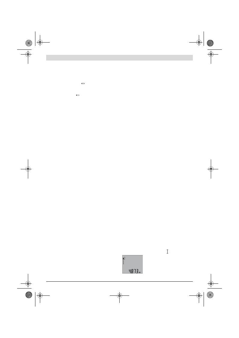
Slovensko |
135
Bosch Power Tools
2 609 140 773 | (4.12.12)
te baterije oz. akumulatorske baterije. Pri tem pazite na pra-
vilnost polov, kot je prikazano na notranji strani predalčka za
baterije.
Pri vstavljanju baterij oz. akumulatorskih baterij pazite na pra-
vilnost polov z ozirom na prikaz v predalčku za baterije.
Ko se pojavi simbol za baterijo
prvič na displeju, je možno
nato opraviti še najmanj 100 posameznih meritev. Funkcija
stalna meritev je deaktivirana.
Če utripa simbol o bateriji
morate menjati baterije oz. aku-
mulatorske celice. Merjenja niso več mogoča.
Zamenjati morate vedno vse baterije oz. akumulatorske bate-
rije. Uporabite samo baterije ali akumulatorske baterije enega
proizvajalca in z enako kapaciteto.
Če merilnega orodja dalj časa ne uporabljate, vzemite
baterije iz merilnega orodja.
Baterije in akumulatorske
baterije lahko pri daljšem skladiščenju korodirajo in se sa-
mostojno izpraznejo.
Delovanje
Zagon
Vklopljenega merilnega orodja nikoli ne puščajte brez
nadzorstva in ga po uporabi izklopite.
Laserski žarek lah-
ko zaslepi druge osebe.
Zavarujte merilno orodje pred vlago in direktnim sonč-
nim sevanjem.
Ne izpostavljajte merilnega orodja ekstremnim tempe-
raturam ali ekstremnemu nihanju temperature.
Poskr-
bite za to, da npr. ne bo ležalo dalj časa v avtomobilu. Če je
merilno orodje bilo izpostavljeno večjim temperaturnim ni-
hanjem, najprej pustite, da se temperatura pred uporabo
uravna. Pri ekstremnih temperaturah ali temperaturnih ni-
hanjih se lahko poškoduje natančnost delovanja merilnega
orodja.
Preprečite močne sunke v merilno orodje ali padce na
tla.
Po močnih zunanjih vplivih na merilno orodje morate
pred nadaljevanjem dela vedno izvesti pregled natančnosti
(glejte „Preizkus natančnosti merjenja dolžine“,
stran 137).
Vklop/izklop
Za
vklop
merilnega orodja imate naslednje možnosti:
– Pritisk na vklopno/izklopno tipko
4
: Merilno orodje se vklo-
pi in se nahaja v funkciji merjenja dolžine. Laser se ne vklo-
pi.
– Pritisk na tipko merjenje
2
: Merilno orodje in laser se vklo-
pita. Merilno orodje se nahaja v funkciji merjenja dolžine.
Laserskega žarka ne usmerjajte na osebe ali živali in ne
glejte vanj, tudi ne iz večje razdalje.
Za
izklop
merilnega orodja pritisnite za dalj časa na vklopno/
izklopno tipko
4
.
Če pribl. 5 min ne pritisnete nobene tipke na merilnem orod-
ju, se merilno orodje zaradi varovanja baterij avtomatsko iz-
klopi.
Postopek meritve
Po vklopu se po pritisku na tipko merjenje
2
merilno orodje
vedno nahaja v funkciji merjenja dolžine. Druge merilne funk-
cije lahko nastavite s pritiskom ustrezne funkcijske tipke (glej-
te „Merilne funkcije“, stran 135).
Zadnji rob merilnega orodja je po vklopu izbrana referenčna
ravnina za merjenje. S pritiskom tipke referenčne ravnine
6
lahko spremenite referenčno ravnino (glejte „Izbira referenč-
ne ravnine“, stran 135).
Namestite merilno orodje z izbrano referenčno ravnino na že-
ljeno startno točko merjenja (npr. steno).
Za vklop laserskega žarka pritisnite za kratek čas na tipko za
merjenje
2
.
Laserskega žarka ne usmerjajte na osebe ali živali in ne
glejte vanj, tudi ne iz večje razdalje.
Ciljajte z laserskim žarkom na ciljno površino. Za sprožitev
merjenja ponovno za kratek čas pritisnite na tipko za merjenje
2
.
V funkciji stalnega merjenja se prične merjenje takoj pri vklo-
pu funkcije.
Merska vrednost se pojavi običajno v roku 0,5 s in najkasneje
po 4 s. Trajanje merjenja je odvisno od razdalje, svetlobnih
razmer in odbojnih lastnosti ciljne površine. Po končanju mer-
jenja se laserski žarek avtomatsko izklopi.
Če po približno 20 s po viziranju ni opravljena nobena meri-
tev, se laserski žarek zaradi ohranitve baterij samodejno izklo-
pi.
Izbira referenčne ravnine (glejte sliko A)
Pri merjenju lahko izbirate med tremi različnimi referenčnimi
ravninami:
– zadnji rob merilnega orodja (npr. pri prislonitvi na stene),
– sprednji rob merilnega orodja (npr. pri merjenju z roba mi-
ze),
– sredina navoja
14
(npr za merjenja s stativom).
Za izbiro referenčne ravnine pritisnite tipko
6
tako dolgo, do-
kler se na displeju ne prikaže željena referenčna ravnina. Pri
vsakem vklopu merilnega orodja je zadnji rob merilnega orod-
ja prednastavljen kot referenčna ravnina.
Osvetlitev displeja
Osvetlitev displeja se glede na svetlost okolice aktivira avto-
matsko. Če po vklopu osvetlitve displeja ne pritisnite na nobe-
no tipko, se zaradi varovanja baterij osvetlitev regulira nav-
zdol.
Merilne funkcije
Enostavno merjenje dolžine (glejte sliko B)
Za merjenje dolžine pritisnite tipko
9
tolikokrat, da se na dis-
pleju pojavi prikaz za merjenje dolžine .
Za vklop laserja in za merjenje pritisnite
za kratek čas na tipko za merjenje
2
.
Merilna vrednost se prikaže v vrstici z re-
zultatom
b
.
OBJ_BUCH-1444-004.book Page 135 Tuesday, December 4, 2012 1:47 PM
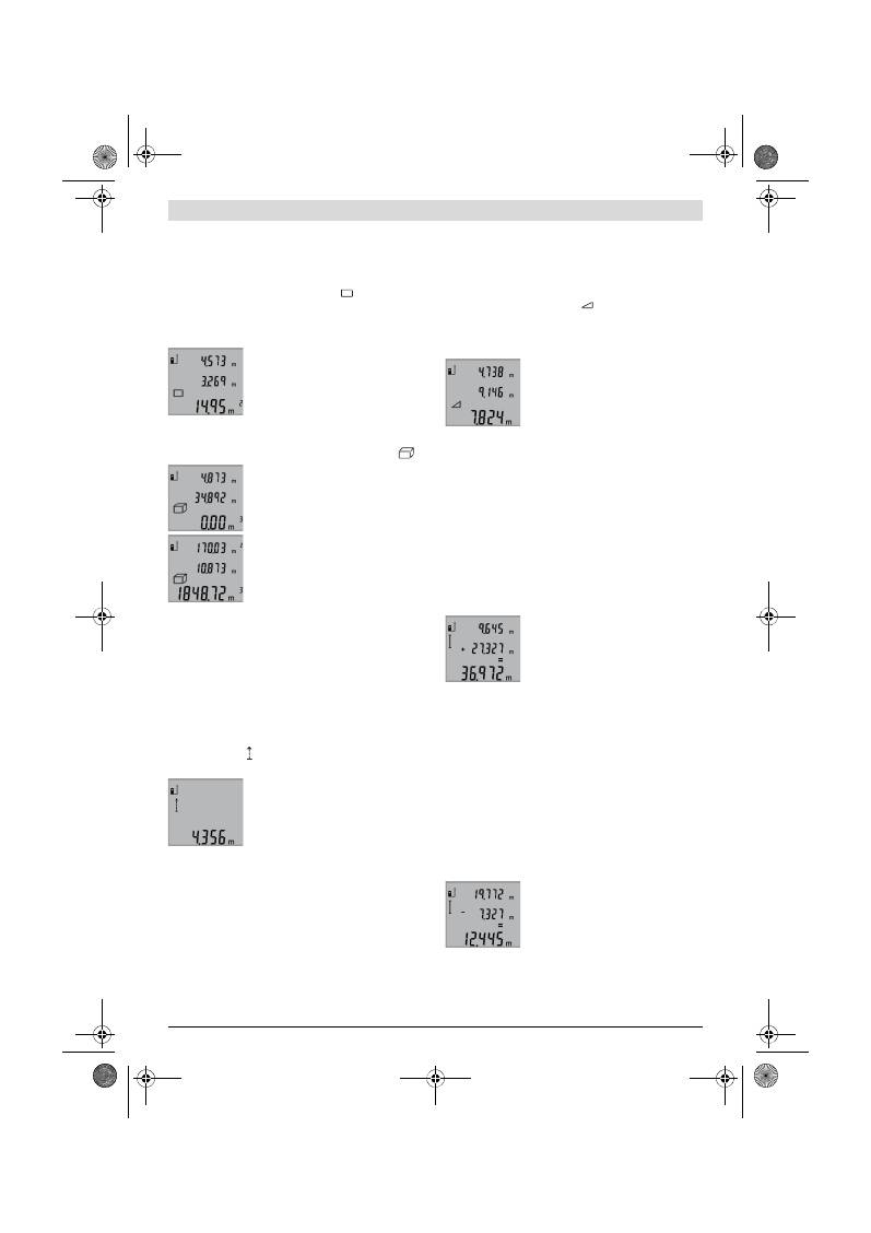
136
| Slovensko
2 609 140 773 | (4.12.12)
Bosch Power Tools
Pri večjem številu zaporednih meritev dolžine se prikažejo re-
zultati zadnjih meritev v vrsticah merilnih vrednosti
a
.
Ploskovna meritev (glejte sliko C)
Za merjenje površine pritisnite tipko
3
tolikokrat, da se na di-
spleju pojavi prikaz za merjenje površine
.
Zdaj zaporedoma merite dolžino in širino, katero merite na
enak način kot dolžino. Med obema meritvama ostane laserski
žarek vklopljen.
Po zaključku druge meritve se površina
samodejno izračuna, prikaže se vrstica z
rezultatom
b
. Posamezne merilne vre-
dnosti se nahajajo v vrsticah z mersko vre-
dnostjo
a
.
Prostorska meritev (glejte sliko D)
Za merjenje prostornine pritisnite tipko
3
tako dolgo, dokler
se na displeju ne pojavi prikaz za merjenje prostornine
.
Zaporedoma merite dolžino, širino in viši-
no, na enak način kot pri meritvi dolžine.
Med meritvami ostane laserski žarek vklo-
pljen.
Po zaključku tretje meritve, se prostorni-
na samodejno izračuna, prikaže se vrstica
z rezultatom
b
. Posamezne merilne vre-
dnosti se nahajajo v vrsticah z mersko
vrednostjo
a
.
Vrednosti nad 999999 m
3
se ne morejo prikazati, na displeju
se pojavi
„ERROR“
. Prostornino, ki jo želite izmeriti, razdelite
v posamezne meritve in njihove vrednosti ločeno izračunajte
in jih nato združite.
Stalna meritev (glejte sliko E)
Pri stalni meritvi lahko merilno orodje pomaknete relativno k
cilju, pri čemer se merilna vrednost aktualizira pribl. vseh
0,5 s. Lahko se npr. oddaljite od stene do željenega razmaka,
aktualno razdaljo je vedno moč odčitati.
Za trajna merjenja pritisnite tipko
9
tako dolgo, da se na dis-
pleju pojavi prikaz za trajno meritev. Za pričetek trajnega
merjenja pritisnite na tipko za merjenje
2
.
Aktualna merilna vrednost se prikaže v vr-
stici z rezultatom
b
.
S pritiskom na tipko merjenje
2
končate s
trajnim merjenjem. Zadnja merilna vre-
dnost se prikaže v vrstici z rezultatom
b
.
Ponovni pritisk tipke za merjenje
2
znova
starta trajno merjenje.
Stalno merjenje se po 5 min avtomatsko izklopi. Zadnja meril-
na vrednost se ohrani v vrstici z rezultatom
b
.
Indirektno merjenje višine / Enostavno merjenje po Pita-
gorovem izreku (glejte sliko F)
Z indirektnim merjenjem višine izračunate razdalje, ki jih ni
moč direktno izmeriti, npr. zaradi ovire, ki je napoti žarku ali
ker ni na razpolago ciljne površine za reflekcijo. Pravilni rezul-
tati se dosežejo le tedaj, ko se pri konkretnem merjenju upo-
števajo natančni pravi koti (Pitagorov izrek).
Pazite na to, da ostane referenčna točka meritve (npr. zadnji
rob merilnega orodja) pri vseh posameznih meritvah znotraj
postopka merjenja na natančno enakem mestu.
Med posameznimi meritvami ostane laserski žarek vklopljen.
Pritisnite tipko
3
tolikokrat, da se na displeju pojavi prikaz za
merjenje po Pitagorovem izreku
.
Na isti način, kot pri merjenju dolžine, izmerite poti
„1“
in
„2“
v tem vrstnem redu. Pri tem pazite na to, da med potjo
„1“
in
iskano potjo
„X“
obstaja pravi kot.
Po zaključku zadnje meritve se prikaže re-
zultat za željeno pot
„X“
v vrstici z rezulta-
ti
b
. Posamezne merilne vrednosti se na-
hajajo v vrsticah z mersko vrednostjo
a
.
Brisanje merskih vrednosti
S kratkim pritiskom na tipko
4
lahko v vseh funkcijah merjenja
izbrišete zadnje izračunane posamezne merske vrednosti. Z
večkratnim kratkim pritiskom na tipko izbrišete vse posame-
zne merske vrednosti v obratnem vrstnem redu.
Seštevanje merilnih vrednosti
Če želite merilne vrednosti seštevati, morate najprej izvesti
poljubno meritev. Nato pritisnite tipko plus
8
. Na displeju se v
potrditev pojavi
„+“
.
Da bi sešteli prostornine ali površine, pritisnite po prvi zaklju-
čenem postopku merjenja tipko plus
8
. Na displeju se v potr-
ditev pojavi
„+“
levo od simbola za prostornino/površino.
Nato opravite drugo meritev.
Za odpoklic vsote obeh meritev pritisnite
tipko plus
8
. V vrsticah z merilno vredno-
stjo
a
se prikaže izračun, vsota se nahaja v
vrstici z rezultatom
b
.
Po izračunu vsote lahko k temu rezultatu
seštejete druge merilne vrednosti, če
pred vsakih merjenjem pritisnete konkretno tipko plus
8
.
Navodila za seštevanje:
– Vrednosti dolžin, površin in prostornin se ne morejo meša-
no seštevati. Če npr. seštejete vrednost dolžine in površi-
ne, se pri pritisku tipke plus
8
za kratek čas pojavi na dis-
pleju
„ERROR“
. Nato menja merilno orodje v zadnjo aktiv-
no merilno funkcijo.
– Sešteje se vedno rezultat ene meritve (npr. vrednost pro-
stornine), pri stalnih meritvah pa merilna vrednost, ki je
prikazana v vrstici z rezultatom
b
. Ni možno seštevanje po-
sameznih merilnih vrednosti iz vrstic z merilnimi vrednost-
mi
a
.
Odštevanje merskih vrednosti
Za odštevanje merilnih vrednosti pritisni-
te tipko minus
5
, na displeju se pojavi v
potrditev
„–“
. Nadaljni postopek je ana-
logen postopku „Seštevanje merilnih vre-
dnosti“.
Navodila za delo
Splošna navodila
Sprejemna leča
12
in izhod laserskega žarka
11
med meritvijo
ne smeta biti zakrita.
OBJ_BUCH-1444-004.book Page 136 Tuesday, December 4, 2012 1:47 PM
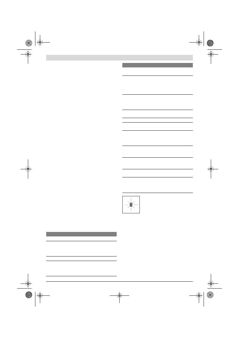
Slovensko |
137
Bosch Power Tools
2 609 140 773 | (4.12.12)
Merilno orodje se med merjenjem ne sme premikati (z izjemo
funkcij trajnega merjenja). Zaradi tega po možnosti položite
merilno orodje ob ali na fiksne prislonitvene ali naležne povr-
šine.
Vplivi na merilno območje
Merilno območje je odvisno od svetlobnih razmer in odbojnih
lastnosti ciljne površine. Za boljšo vidljivost laserskega žarka
pri opravilih na prostem in pri močnem vpadu sonca uporabi-
te očala za vidnost laserskega žarka
19
(pribor) in lasersko
ciljno tablo
20
(pribor) ali pa osenčite ciljno površino.
Vplivi na rezultat meritve
Zaradi fizikalnih učinkov ne moremo izključiti napak pri merje-
nju na več vrstah površin. To so naslednje površine:
– prozorne površine (npr. steklo, voda),
– zrcalne površine (npr. polirana kovina, steklo),
– porozne površine (npr. izolirni materiali),
– strukturirane površine (npr. grob omet, naravni kamen).
Na teh površinah po potrebi uporabite lasersko cilijno tablo
20
(pribor).
Poleg tega so napačne meritve možne na ciljnih površinah, na
katere ste poševno ciljljali.
Prav tako lahko na mersko vrednost vplivajo zračni sloji različ-
nih temperatur ali pa indirektne reflekcije.
Preizkus natančnosti merjenja dolžine
Natančnost merjenja dolžine lahko preverite, kot sledi:
– Izberite merilno območje dolžine pribl. 1 do 10 m, ki se ne
spreminja in njegovo dolžino zanesljivo poznate (npr. širi-
na prostora, odprtina vrat). Merilno območje se mora na-
hajati v notranjem prostoru, ciljna površina merjenja mora
biti gladka in se mora dobro odbijati.
– Območje izmerite 10-krat zaporedoma.
Odkloni posameznih meritev od srednje vrednosti smejo zna-
šati maksimalno ±2 mm. Zabeležite si merjenja, da boste lah-
ko kasneje primerjali natančnost.
Delo s stativom (pribor)
Še posebej pri večjih razdaljah je nujna uporaba stativa. Po-
stavite merilno orodje s 1/4"-navojem
14
na menjalno ploščo
stativa
18
ali na običajni komercialni fotostativ. Privijte ga z
nastavitvenim vijakom menjalne plošče.
Ustrezno referenčno ravnino za meritev s stativom nastavite s
pritiskanjem tipke
6
(referenčna ravnina je navoj).
Napake – Vzroki in pomoč
Merilno orodje pri vsaki meritvi samo nadzi-
ra pravilno delovanje. Če ugotovi, da je pri-
šlo do okvare, je na zaslonu vidno samo še
utripanje simbola. V takem primeru, oziro-
ma če zgoraj navedeni ukrepi pri odstranitvi
napake ne pomagajo, prek Vašega trgovca
dostavite merilno orodje v servisno delavnico Bosch.
Vzdrževanje in servisiranje
Vzdrževanje in čiščenje
Merilno orodje lahko hranite in transportirate samo v priloženi
zaščitni torbi.
Merilno orodje naj bo vedno čisto.
Merilnega orodja nikoli ne potapljajte v vodo ali v druge teko-
čine.
Umazanijo obrišite z vlažno, mehko krpo. Uporaba čistil in to-
pil ni dovoljena.
Še posebno sprejemno lečo
12
morate negovati z enako skrb-
nostjo, kot negujete očala ali lečo fotoaparata.
Vzrok
Pomoč
Opozorilo o temperaturi (f) utripa, merjenje ni možno
Merilno orodje je izven obrato-
valne temperature – 10 °C do
+50 °C (v funkciji trajnega merje-
nja do +40 °C).
Počakajte, da bo merilno
orodje doseglo delovno
temperaturo
Prikaz „ERROR“ na displeju
Prištevanje/odštevanje merskih
vrednosti z različnimi merskimi
enotami
Prištevajte/odštevajte
samo merske vrednosti z
enakimi merskimi
enotami
Preoster kot med laserskim žar-
kom in ciljem.
Povečajte kot med laser-
skim žarkom in ciljem
Premočna refleksija ciljne ploskve
(na primer ogledalo) oziroma pre-
šibka refleksija ciljne ploskve (na
primer črna snov) ali premočno
osvetljena okolica.
Uporabite lasersko cilj-
no tablo
20
(pribor)
Izhod laserskega žarka
11
oziroma
sprejemna leča
12
sta zarosena
(na primer zaradi hitre tempera-
turne spremembe).
Izhod laserskega žarka
11
oziroma sprejemno
lečo
12
obrišite z mehko
krpo
Izračunana vrednost je večja kot
999999 m/m
2
/m
3
.
Izračunavanje razdelite v
delne korake
Rezultat meritve ni prepričljiv
Nejasno reflektiranje ciljne plo-
skve (na primer vode, stekla).
Pokrijte ciljno ploskev
Zakrit izhod laserskega žarka
11
oziroma zakrita sprejemna leča
12
.
Izhod laserskega žarka
11
oziroma sprejemna
leča
12
naj bosta vedno
nezakrita
Nastavljena je napačna referenčna
ravnina
Izberite pravilno refe-
renčno ravnino za meri-
tev
Ovira na poti laserskega žarka
Laserska točka mora le-
žati v celoti na ciljni po-
vršini.
Prikaz ostane nespremenjen ali merilno orodje reagira
nepričakovano na pritisk tipke
Napaka programske opreme
Vzemite baterije ven in
po ponovni namestitvi
ponovno zaženite meril-
no orodje.
Vzrok
Pomoč
OBJ_BUCH-1444-004.book Page 137 Tuesday, December 4, 2012 1:47 PM
138
| Hrvatski
2 609 140 773 | (4.12.12)
Bosch Power Tools
Če merilna naprava kljub skrbnim postopkom proizvodnje in
preizkusov ne deluje, morate poskrbeti za to, da se popravilo
izvede s strani pooblaščenega servisa za električna orodja Bo-
sch. Merilnega orodja sami ne smete odpirati.
V primeru kakršnihkoli vprašanj in pri naročanju nadomestnih
delov obvezno navedite 10-mestno številko artikla, ki se na-
haja na tipski ploščici merilnega orodja.
Merilno orodje pošljite na popravilo v zaščitni torbi
17
.
Servis in svetovanje o uporabi
Servis Vam bo dal odgovore na Vaša vprašanja glede popravi-
la in vzdrževanja izdelka ter nadomestnih delov. Risbe razsta-
vljenega stanja in informacije o nadomestnih delih se nahajajo
tudi na spletu pod:
www.bosch-pt.com
Skupina svetovalcev o uporabi podjetja Bosch Vam bo z vese-
ljem v pomoč pri vprašanjih o naših izdelkih in njihovega pri-
bora.
Slovensko
Top Service d.o.o.
Celovška 172
1000 Ljubljana
Tel.: (01) 519 4225
Tel.: (01) 519 4205
Fax: (01) 519 3407
Odlaganje
Merilna orodja, pribor in embalažo oddajte v okolju prijazno
ponovno predelavo.
Merilna orodja in akumulatorskih baterij/baterij ne smete od-
vreči med hišne odpadke!
Samo za države EU:
V skladu z Direktivo 2002/96/ES se morajo
merilna orodja, ki niso več v uporabi ter v
skladu z Direktivo 2006/66/ES morate
okvarjene ali obrabljene akumulatorske ba-
terije/baterije zbirati ločeno in jih okolju pri-
jazno reciklirati.
Pridržujemo si pravico do sprememb.
Hrvatski
Upute za sigurnost
Sve upute treba pročitati i pridržavati ih
se, kako bi se sa mjernim alatom moglo ra-
diti bezopasno i sigurno. Znakove i natpise
upozorenja na mjernom alatu održavajte
čitljivim. OVE UPUTE SPREMITE NA SIGUR-
NO MJESTO.
Oprez – ako se koriste uređaji za posluživanje ili pode-
šavanje različiti od onih ovdje navedenih ili se izvode
drugačiji postupci, to može dovesti do opasnih izlaga-
nja zračenju.
Mjerni alat se isporučuje sa natpisom upozorenja na en-
gleskom jeziku (na prikazu mjernog alata na stranici sa
slikama, označen brojem 15).
Prije prve uporabe na naljepnicu sa engleskim tekstom
nalijepite isporučenu naljepnicu na Vašem materinjem
jeziku.
Lasersku zraku ne usmjeravajte na ljude ili životinje i ne
gledajte izravno u lasersku zraku.
Ovaj mjerni alat proi-
zvodi lasersko zračenje klase lasera 2, prema
IEC 60825-1. Zbog toga možete zaslijepiti ljude.
Naočale za gledanje lasera ne koristite kao zaštitne na-
očale.
Naočale za gledanje lasera služe za bolje prepozna-
vanje laserske zrake, međutim one ne mogu zaštititi od la-
serskog zračenja.
Naočale za gledanje lasera ne koristite kao sunčane na-
očale ili u cestovnom prometu.
Naočale za gledanje lase-
ra ne služe za potpunu zaštitu od ultraljubičastih zraka i
smanjuju sposobnost za razlikovanje boja.
Popravak mjernog alata prepustite samo kvalificira-
nom stručnom osoblju i samo sa originalnim rezervnim
dijelovima.
Na taj će se način postići da ostane zadržana
sigurnost mjernog alata.
Ne dopustite djeci da bez nadzora koriste laserski mjer-
ni alat.
Djeca bi mogla nehotično zaslijepiti druge ljude.
Sa mjernim alatom ne radite u okolini ugroženoj ek-
splozijom, u kojoj se nalaze zapaljive tekućine, plinovi
ili prašina.
U mjernom alatu mogu nastati iskre koje mogu
zapaliti prašinu ili pare.
Opis proizvoda i radova
Molimo otvorite preklopnu stranicu s prikazom mjernog alata
i držite ovu stranicu otvorenom dok čitate upute za uporabu.
Uporaba za određenu namjenu
Mjerni alat je predviđen za mjerenje udaljenosti, dužina, visi-
na, razmaka i za izračunavanje površina i volumena. Mjerni
alat je prikladan za mjerenje u zatvorenim prostorima i na
otvorenom.
OBJ_BUCH-1444-004.book Page 138 Tuesday, December 4, 2012 1:47 PM

Hrvatski |
139
Bosch Power Tools
2 609 140 773 | (4.12.12)
Tehnički podaci
Prikazani dijelovi uređaja
Numeriranje prikazanih komponenti odnosi se na prikaz mjer-
nog alata na stranici sa slikama.
1
Displej
2
Tipka za mjerenje
3
Tipka za mjerenje površina, volumena i neizravno mjere-
nje visina (Pitagorino mjerenje)
4
Tipka za brisanje / tipka za uključivane-isključivanje **
5
Tipka za minus
6
Tipka za biranje referentne ravnine
7
Prihvat omče za nošenje
8
Tipka za plus
9
Tipka za mjerenje dužina i stalno mjerenje
10
Poklopac pretinca za baterije
11
Izlaz laserskog zračenja
12
Prijemna leća
13
Serijski broj
14
1/4" navoj
15
Znak upozorenja za laser
16
Aretiranje poklopca pretinca za baterije
17
Zaštitna torbica
18
Stativ*
19
Naočale za gledanje lasera*
20
Laserska ciljna ploča*
* Prikazan ili opisan pribor ne pripada standardnom opsegu isporu-
ke.
** Za pokazivanje proširenih funkcija treba pritisnuti i držati priti-
snutu tipku.
Digitalni laserski daljinomjer
GLM 50
Professional
Kataloški br.
3 601 K72 2..
Mjerno područje
0,05 –50 m
A)
Točnost mjerenja (tipična)
±1,5 mm
B)
Najmanja pokazana jedinica
1 mm
Radna temperatura
–10 °C...+50 °C
C)
Temperatura uskladištenja
–20 °C...+70 °C
Relativna vlažnost max.
90 %
Klasa lasera
2
Tip lasera
635 nm, <1 mW
Promjer laserske zrake (kod 25 °C) cca.
– na 10 m udaljenosti
– na 50 m udaljenosti
6 mm
35 mm
Automatika isključivanja nakon cca.
– Laserski
– mjerni alat (bez mjerenja)
20 s
5 min
Baterije
Aku-baterije
2 x 1,5 V LR03 (AAA)
2 x 1,2 V HR03 (AAA)
Vijek trajanja baterije cca.
– pojedinačna mjerenja
– stalno mjerenje
10000
D)
2,5 h
D)
Težina odgovara EPTA-Procedure 01/2003
0,14 kg
Dimenzije
53 x 114 x 30 mm
Vrsta zaštite
IP 54 (zaštićen od prašine i prskanja vode)
A) Doseg će biti veći što se bolje lasersko svjetlo odbija od površine cilja (raspršivanjem, ne zrcalno) i što je svjetlija laserska točka u odnosu na svjetlo
okoline (unutarnji prostori, polumrak). Kod nepovoljnih uvjeta (npr. mjerenje na otvorenom prostoru s jakim sunčevim zračenjem) može se ukazati po-
trebnim korištenje ciljne ploče.
B) Kod mjerenja počevši od stražnjeg ruba mjernog alata. Kod nepovoljnih uvjeta, kao npr. jako sunčevo zračenje ili slabo reflektirajuće površine, mak-
simalno odstupanje iznosi
±
10 mm na 50 m. Kod povoljnih uvjeta treba računati sa utjecajem od
±
0,05 mm/m.
C) U funkciji stalnog mjerenja, maksimalna radna temperatura iznosi +40
°C
.
D) S 1,2 V aku-baterijama može se postići manji broj mjerenja nego s 1,5 V baterijama. Navedeni vijek trajanja baterija odnosi se na mjerenja bez osvjet-
ljenja displeja.
Za jednoznačno identificiranje vašeg mjernog alata služi serijski broj
13
na tipskoj pločici.
OBJ_BUCH-1444-004.book Page 139 Tuesday, December 4, 2012 1:47 PM

140
| Hrvatski
2 609 140 773 | (4.12.12)
Bosch Power Tools
Pokazni elementi
a
Reci izmjerene vrijednosti
b
Redak rezultata
c
Funkcije mjerenja
d
Uključen laser
e
Referentna ravnina mjerenja
f
Upozorenje za temperaturu
g
Upozorenje za bateriju
h
Pokazivač greške
„ERROR“
Montaža
Stavljanje/zamjena baterije
Za rad mjernog alata preporučuje se primjena alkalno-man-
ganskih baterija ili aku-baterije.
Sa 1,2 V aku-baterijom moguć je manji broj mjerenja nego sa
1,5 V baterijama.
Za otvaranje poklopca pretinca za baterije
10
pritisnite areti-
ranje
16
i skinite poklopac pretinca za baterije. Stavite bateri-
je, odnosno aku-baterije. Kod toga pazite na ispravan polari-
tet prema shemi na unutarnjoj strani pretinca za baterije.
Kod stavljanja baterija, odnosno aku-baterija pazite na ispra-
van polaritet prema shemi u pretincu za baterije.
Ako bi se simbol baterije
prvi puta pojavio na displeju, tada
je moguće još daljnjih 100 pojedinačnih mjerenja. Funkcija
stalnog mjerenja je deaktivirana.
Ako bi treperio simbol baterije
, moraju se zamijeniti bate-
rije, odnosno aku-baterije. Mjerenja više nisu moguća.
Uvijek istodobno zamijenite sve baterije, odnosno aku-bateri-
ju. Koristite samo baterije ili aku-bateriju istog proizvođača i
istog kapaciteta.
Baterije, odnosno aku-bateriju izvadite iz mjernog ala-
ta ako se dulje vrijeme neće koristiti.
Baterije i aku-bate-
rija kod duljeg uskladištenja mogu korodirati i sami se
isprazniti.
Rad
Puštanje u rad
Uključeni mjerni alat ne ostavljajte bez nadzora i isklju-
čite mjerni alat nakon uporabe.
Laserska zraka bi mogla
zaslijepiti ostale osobe.
Zaštitite mjerni alat od vlage i izravnog djelovanja sun-
čevih zraka.
Mjerni alat ne izlažite ekstremnim temperaturama ili
oscilacijama temperature.
Ne ostavljajte ga npr. dulje vri-
jeme u automobilu. Kod većih temperaturnih oscilacija,
prije nego što ćete ga pustiti u rad, ostavite mjerni alat da
se prvo temperira. Kod ekstremnih temperatura ili oscilaci-
ja temperature može se smanjiti preciznost mjernog alata.
Izbjegavajte snažne udarce ili padove mjernog alata.
Nakon jačih vanjskih djelovanja na mjerni alat, prije dalj-
njeg rada morate uvijek provesti provjeru točnosti (vidjeti
„Provjera točnosti mjerenja udaljenosti“, stranica 142).
Uključivanje/isključivanje
Za
uključivanje
mjernog alata imate slijedeće mogućnosti:
– Pritisnite na tipku za uključivanje/isključivanje
4
: Mjerni
alat će se uključiti i nalazi se u funkciji mjerenja dužina. La-
ser se neće uključiti.
– Pritisnite na tipku za mjerenje
2
: Uključit će se mjerni alat i
laser. Mjerni alat se nalazi u funkciji mjerenja dužina.
Ne usmjeravajte lasersku zraku na ljude ili životinje i ne
gledajte u lasersku zraku, niti sa veće udaljenosti.
Za
isključivanje
mjernog alata, dulje vrijeme pritisnite na tip-
ku za uključivanje/isključivanje
4
.
Ako se cca. 5 min. na mjernom alatu ne bi pritisnula niti jedna
tipka, tada će se mjerni alat automatski isključiti za čuvanje
baterija.
Postupak mjerenja
Nakon uključivanja pritiskom na tipku mjerenja
2
, mjerni alat
se uvijek nalazi u funkciji mjerenja dužina. Ostale funkcije mje-
renja mogu se podesiti pritiskom na pripadajuću funkcijsku
tipku (vidjeti „Funkcije mjerenja“, stranica 141).
Kao referentna razina za mjerenje nakon uključivanja, oda-
bran je stražnji rub mjernog alata. Pritiskom na tipku referen-
tne razine
6
, možete promijeniti referentnu razinu (vidjeti „Bi-
ranje referentne razine“, stranica 140).
Mjerni alat sa odabranom referentnom ravninom stavite na
traženu početnu točku mjerenja (npr. zid).
Za uključivanje laserske zrake, kratko pritisnite na tipku za
mjerenje
2
.
Ne usmjeravajte lasersku zraku na ljude ili životinje i ne
gledajte u lasersku zraku, niti sa veće udaljenosti.
Vizirajte sa laserskom zrakom ciljnu površinu. Za aktiviranje
mjerenja pritisnite jedan šuta kratko na tipku za mjerenje
2
.
U funkciji stalnog mjerenja, mjerenje počinje odmah nakon
uključivanja funkcije.
Izmjerena se vrijednost obično pojavljuje u toku 0,5 s, ali naj-
kasnije nakon 4 s. Trajanje mjerenja ovisi od udaljenosti, uvje-
ta svjetla i svojstava refleksije ciljne površine. Nakon završe-
nog mjerenja laserska zraka će se automatski isključiti.
Ako se 20 s nakon postavljanja cilja ne provodi nikakvo mjere-
nje, laserska zraka će se automatski isključiti za očuvanje ba-
terija.
Biranje referentne razine (vidjeti sliku A)
Za mjerenje možete birati među tri različite referentne ravni-
ne:
– stražnji rub mjernog alata (npr. kod polaganja na zidove),
– prednji rubovi mjernog alata (npr. kod mjerenja počevši od
jednog ruba stola),
Mjerenje dužina
Stalno mjerenje
Mjerenje površina
Mjerenje volumena
Jednostruko Pitagorino mjerenje
OBJ_BUCH-1444-004.book Page 140 Tuesday, December 4, 2012 1:47 PM
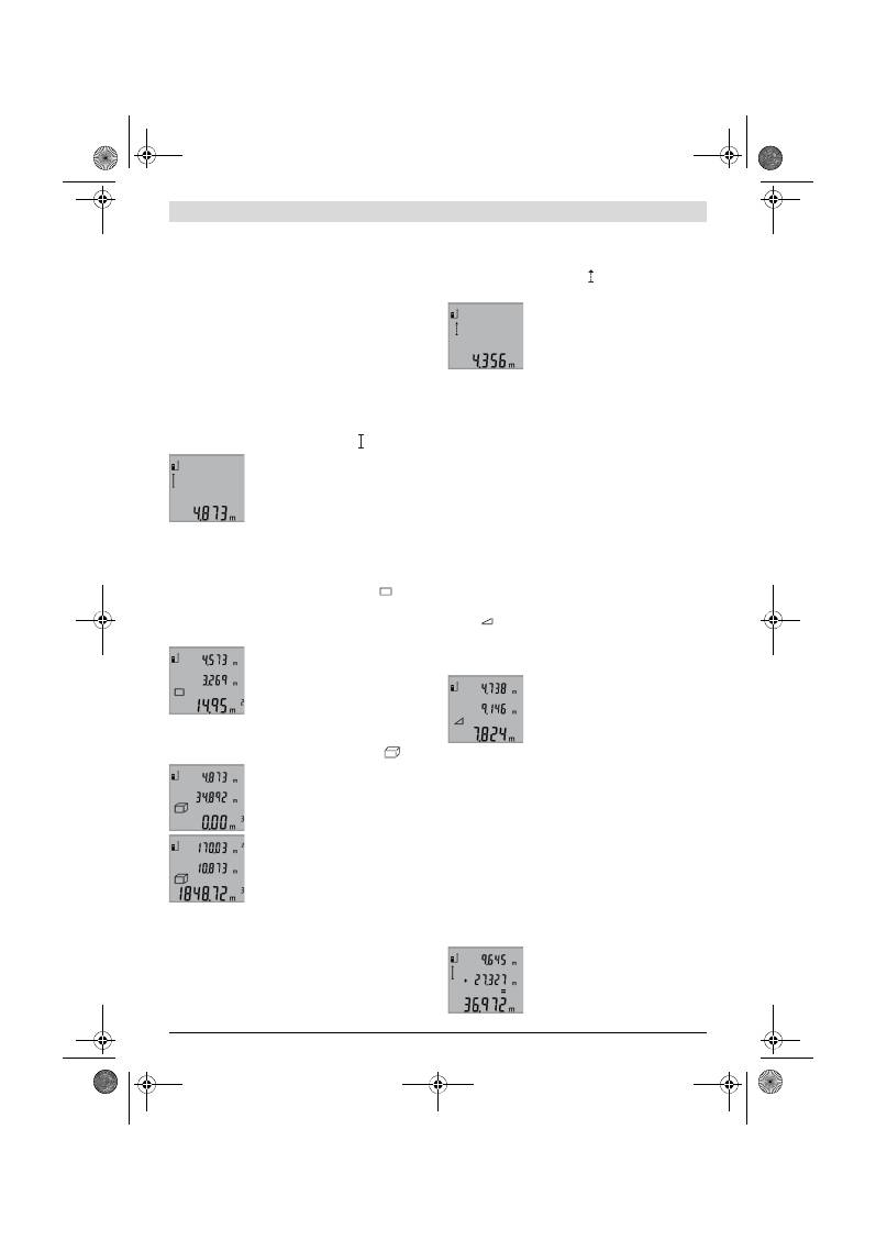
Hrvatski |
141
Bosch Power Tools
2 609 140 773 | (4.12.12)
– središte navoja
14
(npr. za mjerenja sa stativom).
Za biranje referentne ravnine, tipku
6
pritišćite toliko često
dok se na displeju ne pokaže tražena referentna razina. Nakon
svakog uključivanja mjernog alata, stražnji rub mjernog alata
je prethodno podešen kao referentna razina.
Osvjetljenje displeja
Osvjetljenje displeja će se automatski uključiti ovisno od svje-
tloće okoline. Ako se nakon uključivanja osvjetljenja displeja
ne bi pritisnula niti jedna tipka, ono će se prigušiti u svrhu oču-
vanja baterija.
Funkcije mjerenja
Jednostruko mjerenje dužina (vidjeti sliku B)
Za mjerenja dužina pritišćite tipku
9
toliko često dok se na dis-
pleju ne pojavi pokazivač za mjerenje dužina .
Za uključivanje lasera i za mjerenje priti-
snite jedan puta kratko na tipku za mjere-
nje
2
.
Izmjerena vrijednost će se pokazati u ret-
ku rezultata
b
.
Kod više mjerenja dužine jednih iza drugih, u recima izmjere-
nih vrijednosti
a
pokazat će se rezultati zadnjih mjerenja.
Mjerenje površina (vidjeti sliku C)
Za mjerenje površina, tipku
3
pritišćite toliko često dok se na
displeju ne pojavi pokazivač za mjerenje površina
.
Nakon toga mjerite dužinu i širinu jednu iza druge, kao kod
mjerenja dužina. Između oba mjerenja laserska zraka ostaje
uključena.
Nakon završenog drugog mjerenja auto-
matski će se izračunati površina i pokazati
u retku rezultata
b
. Pojedinačne izmjere-
ne vrijednosti nalaze se u recima izmjere-
ne vrijednosti
a
.
Mjerenje volumena (vidjeti sliku D)
Za mjerenje volumena pritišćite tipku
3
toliko često dok se na
displeju ne pojavi pokazivač za mjerenje volumena
.
Nakon toga mjerite dužinu, širinu i visinu
jednu iza druge, kao kod mjerenja dužina.
Između tri mjerenja laserska zraka ostaje
uključena.
Nakon završenog trećeg mjerenja auto-
matski će se izračunati volumen i pokazati
u retku rezultata
b
. Pojedinačne izmjere-
ne vrijednosti nalaze se u recima izmjere-
ne vrijednosti
a
.
Ne mogu se pokazati vrijednosti više od 999999 m
3
, na dis-
pleju se pojavljuje poruka
„ERROR“
. Podijelite mjereni volu-
men na pojedinačna mjerenja, čije vrijednosti zasebno izraču-
najte i nakon toga zbrojite.
Stalno mjerenje (vidjeti sliku E)
Kod stalnog mjerenja mjerni alat se može relativno pomicati
prema cilju, kod čega se izmjerena vrijednost aktualizira na-
kon cca. svakih 0,5 s. Možete se npr. udaljiti od zida do želje-
ne udaljenosti, a trenutačna udaljenost se može uvijek očitati.
Za stalno mjerenje pritišćite tipku
9
dok se na displeju ne po-
javi pokazivač za stalno mjerenje . Za početak stalnog mje-
renja pritisnite tipku za mjerenje
2
.
Trenutačna izmjerena vrijednost pokazat
će se u retku rezultata
b
.
Pritiskom na tipku za mjerenje
2
završava
se stalno mjerenje. Zadnja izmjerena vri-
jednost će se pokazati u retku rezultata
b
.
Ponovnim pritiskom na tipku za mjerenje
2
ponovno započinje stalno mjerenje.
Stalno mjerenje se automatski isključuje nakon 5 minuta. Za-
dnja izmjerena vrijednost ostaje pokazana u retku rezultata
b
.
Neizravno mjerenje visina / Jednostruko Pitagorino mje-
renje (vidjeti sliku F)
Neizravno mjerenje visina služi za određivanje udaljenosti ko-
je se ne mjere izravno, jer postoji zapreka toku zrake ili nema
ciljne površine kao reflektora. Točni rezultati će se postići sa-
mo ako se kod dotičnog mjerenja točno održi traženi pravi kut
(Pitagorin poučak).
Pazite da referentna točka mjerenja (npr. stražnji rub mjernog
alata) kod svih pojedinačnih mjerenja, unutar jednog postup-
ka mjerenja ostane na točno istom mjestu.
Između pojedinačnih mjerenja laserska zraka ostaje uključe-
na.
Tipku
3
pritišćite toliko često dok se na displeju ne pojavi po-
kazivač
za jednostavno Pitagorino mjerenje.
Kod mjerenja dužina, dionice
„1“
i
„2“
mjerite ovim redoslije-
dom. Pazite da između dionice
„1“
i tražene dionice
„X“
po-
stoji pravi kut.
Nakon završenog zadnjeg mjerenja, rezul-
tat za traženu dionicu
„X“
pokazat će se u
retku rezultata
b
. Vrijednosti pojedinač-
nog mjerenja nalaze se u retku izmjerenih
vrijednosti
a
.
Brisanje izmjerenih vrijednosti
Kratkim pritiskom na tipku
4
, u svim funkcijama mjerenja mo-
že se izbrisati zadnje određena pojedinačna vrijednost.
Višekratnim kratkim pritiscima na tipku, pojedinačne izmjere-
ne vrijednosti će se izbrisati obrnutim redoslijedom.
Zbrajanje izmjerenih vrijednosti
Za zbrajanje izmjerenih vrijednosti, najprije izvršite proizvolj-
no mjerenje. Nakon toga pritisnite plus tipku
8
. Na displeju će
se za potvrdu pojaviti
„+“
.
Za zbrajanje volumena ili površina, nakon prvog završenog
postupka mjerenja pritisnite plus tipku
8
. Na displeju će se za
potvrdu pojaviti
„+“
lijevo od simbola mjerenja volumena/ po-
vršina.
Nakon toga izvršite drugo mjerenje.
Za pozivanje zbroja rezultata oba mjere-
nja još jednom pritisnite plus tipku
8
. Izra-
čun će se pokazati retku izmjerenih vrijed-
nosti
a
, a zbroj se nalazi u retku rezultata
b
.
OBJ_BUCH-1444-004.book Page 141 Tuesday, December 4, 2012 1:47 PM
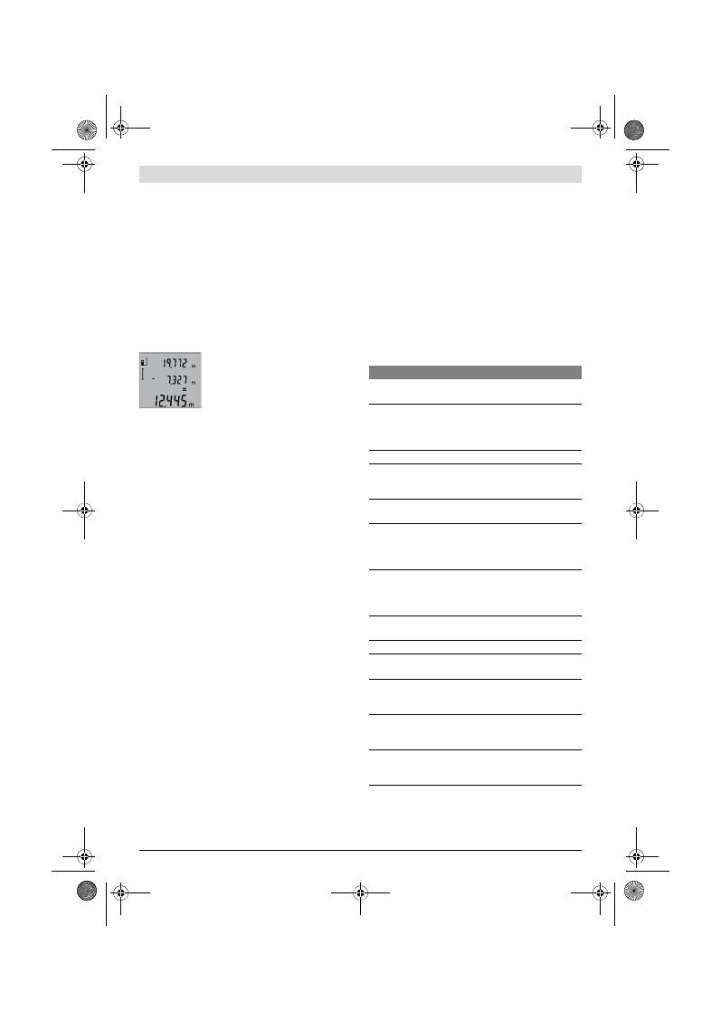
142
| Hrvatski
2 609 140 773 | (4.12.12)
Bosch Power Tools
Nakon izračunavanja zbroja, ovom se rezultatu mogu pribrojiti
i ostale izmjerene vrijednosti, ako se prije mjerenja pritisne
plus tipka
8
.
Upute za zbrajanje:
– Vrijednosti mjerenja dužina, površina i volumena ne mogu
se mješovito zbrajati. Ako se npr. zbraja vrijednost mjere-
nja dužina i površina, kod pritiska na plus tipku
8
, na dis-
pleju će se na kratko pojaviti
„ERROR“
. Nakon toga se
mjerni alat mijenja na zadnje aktivnu funkciju mjerenja.
– Zbraja se rezultat jednog mjerenja (npr. vrijednost volume-
na), a kod stalnog mjerenja izmjerena vrijednost pokazana
u retku rezultata
b
. Nije moguće zbrajanje pojedinačnih iz-
mjerenih vrijednosti iz redaka izmjerenih vrijednosti
a
.
Oduzimanje izmjerenih vrijednosti
Za oduzimanje izmjerenih vrijednosti pri-
tisnite tipku za minus
5
, na displeju će se
za potvrdu pojaviti
„–“
. Daljnji postupak
je sličan „Zbrajanje izmjerenih vrijedno-
sti“.
Upute za rad
Opće napomene
Prijemna leća
12
i izlaz laserskog zračenja
11
ne smiju biti po-
kriveni tijekom mjerenja.
Mjerni alat se ne smije pomicati tijekom mjerenja (sa izuzet-
kom funkcije stalnog mjerenja). Zbog toga mjerni alat po mo-
gućnosti položite na čvrstu graničnu površinu ili površinu nali-
jeganja.
Utjecaji na mjerno područje
Mjerno područje ovisi od uvjeta osvjetljenja i od svojstava re-
fleksije ciljne površine. Za bolju vidljivost laserske zrake kod
rada na otvorenom i kod jačeg sunčevog zračenja, treba nositi
naočale za gledanje lasera
19
(pribor) i ciljnu ploču lasera
20
(pribor), ili zasjenite ciljnu ploču.
Utjecaji na rezultat mjerenja
Zbog fizikalnih efekata ne može se isključiti da kod mjerenja
na različitim površinama dođe do pogrešnih mjerenja. Tu se
ubrajaju:
– prozirne površine (npr. staklo, voda),
– zrcalne površine (npr. polirani metal, staklo),
– porozne površine (npr. izolacijski materijali),
– strukturirane površine (npr. hrapava žbuka, prirodni ka-
men).
Na ovim površinama u danom slučaju koristite ciljnu ploču la-
sera
20
(pribor).
Pogrešna mjerenja su osim toga moguća na koso ciljanim cilj-
nim površinama.
Na izmjerenu vrijednost mogu isto tako utjecati zračni slojevi
različitih temperatura ili neizravno primane refleksije.
Provjera točnosti mjerenja udaljenosti
Točnost mjerenja udaljenosti se provjerava kako slijedi:
– Odaberite mjernu dionicu dužine cca. 1 do 10 m, koja se
neće dulje vrijeme mijenjati i čija dužina vam je točno po-
znata (npr. širina prostorije, otvor vrata). Mjerna dionica
mora se nalaziti unutar zatvorenog prostora, a ciljna povr-
šina mjerenja mora biti glatka i dobro reflektirajuća.
– Dionicu izmjerite 10 puta uzastopno.
Odstupanje pojedinih mjerenja od srednje vrijednosti smije
iznositi maksimalno ±2 mm. Unesite u zapisnik rezultate mje-
renja, kako bi kasnije mogli usporediti točnost.
Radovi sa stativom (pribor)
Primjena stativa je osobito potrebna kod velikih udaljenosti.
Mjerni alat sa 1/4" navojem
14
stavite na brzoizmjenjivu plo-
ču stativa
18
ili na običan fotostativ. Stegnite ga sa steznim
vijkom brzoizmjenjive ploče.
Postavite referentnu razinu za mjerenja sa stativom, odgova-
rajućim pritiskom na tipku
6
(navoj referentne razine).
Greške – uzroci i otklanjanje
Uzrok
Otklanjanje
Upozorenje za temperaturu (f) treperi, mjerenje nije mo-
guće
Mjerni alat se nalazi izvan područja
radne temperature od – 10 °C do
+50 °C (u funkciji stalnog mjere-
nja do +40 °C).
Pričekati dok mjerni alat
postigne radnu tempe-
raturu
Pokazivanje „ERROR“ na displeju
Zbrajanje/oduzimanje izmjerenih
vrijednosti sa različitim mjernim
jedinicama
Zbrajati/oduzimati samo
izmjerene vrijednosti
istih mjernih jedinica
Kut između laserske zrake i cilja je
suviše oštar.
Povećati kut između la-
serske zrake i cilja
Ciljna površina reflektira suviše ja-
ko (npr. zrcalo), odnosno suviše
slabo (npr. crna tvar), ili je okolno
svjetlo suviše jako.
Koristiti lasersku ciljnu
ploču
20
(pribor)
Izlaz laserskog zračenja
11
, odno-
sno prijemna leća
12
su zamagljeni
(npr. zbog brzih temperaturnih
promjena).
Mekom krpom na suho
istrljati izlaz laserskog
zračenja
11
, odnosno
prijemnu leću
12
Izračunata vrijednost je veća od
999999 m/m
2
/m
3
.
Proračun podijeliti u me-
đukorake
Rezultat mjerenja je neprihvatljiv
Ciljna površina ne reflektira jedno-
značno (npr. voda, staklo).
Pokriti ciljnu površinu
Pokriven je izlaz laserskog zrače-
nja
11
, odnosno prijemna leća
12
.
Osloboditi izlaz laser-
skog zračenja
11
, odno-
sno prijemnu leću
12
Namještena pogrešna referentna
razina
Odabrati odgovarajuću
referentnu razinu za
mjerenje
Zapreka na toku laserske zrake
Točka lasera mora ležati
kompletno na ciljnoj po-
vršini.
OBJ_BUCH-1444-004.book Page 142 Tuesday, December 4, 2012 1:47 PM
Eesti |
143
Bosch Power Tools
2 609 140 773 | (4.12.12)
Mjerni alat nadzire ispravnu funkciju kod
svakog mjerenja. Ako bi se ustanovila greš-
ka, tada na displeju treperi još samo simbol
pored. U ovom slučaju ili ako se gore spo-
menutim mjerama pomoći ne može otkloni-
ti neka greška, pošaljite mjerni alat preko
vašeg trgovca u Bosch servis.
Održavanje i servisiranje
Održavanje i čišćenje
Mjerni alat spremite i transportirajte samo u za to isporučenoj
zaštitnoj torbici.
Mjerni alat održavajte uvijek čistim.
Ne uranjajte mjerni alat u vodu ili u druge tekućine.
Prljavštinu obrišite vlažnom, mekom krpom. U tu svrhu ne ko-
ristite nikakva sredstva za čišćenje i otapala.
Njegujte osobito prijemnu leću
12
sa posebnom pažnjom, sa
kojom morate postupati kao kod brisanja leća naočala ili
objektiva fotoaparata.
Ako bi mjerni alat unatoč brižljivih postupaka izrade i ispitiva-
nja ipak prestao raditi, popravak treba prepustiti ovlaštenom
servisu za Bosch električne alate. Ne otvarajte sami mjerni
alat.
Kod svih povratnih upita i naručivanja rezervnih dijelova, mo-
limo neizostavno navedite 10-znamenkasti kataloški broj sa
tipske pločice mjernog alata.
U slučaju popravka pošaljite mjerni alat u zaštitnoj torbici
17
.
Servisiranje i savjetovanje o primjeni
Ovlašteni servis će odgovoriti na vaša pitanja o popravcima i
održavanju vašeg proizvoda te o rezervnim dijelovima. Pove-
ćane crteže i informacije o rezervnim dijelovima možete naći
na adresi:
www.bosch-pt.com
Bosch tim za savjetovanje o primjeni rado će vam pomoći od-
govorom na pitanja o našim proizvodima i priboru.
Hrvatski
Robert Bosch d.o.o
Kneza Branimira 22
10040 Zagreb
Tel.: (01) 2958051
Fax: (01) 2958050
Zbrinjavanje
Mjerne alate, pribor i ambalažu treba dostaviti na ekološki pri-
hvatljivo recikliranje.
Mjerni alat, aku-bateriju/baterije ne bacajte u kućni otpad!
Samo za zemlje EU:
Prema Europskim smjernicama
2002/96/EG, neuporabivi mjerni alati i
prema Smjernicama 2006/66/EG nei-
spravne ili istrošene aku-baterije/ baterije
moraju se odvojeno sakupljati i dovesti na
ekološki prihvatljivo recikliranje.
Zadržavamo pravo na promjene.
Eesti
Ohutusnõuded
Mõõteseadmega ohutu ja turvalise töö ta-
gamiseks lugege läbi kõik juhised ning jär-
gige neid. Ärge katke mõõteseadmel ole-
vaid hoiatussilte kunagi kinni. HOIDKE
KÕIK JUHISED HOOLIKALT ALLES.
Ettevaatust – siin nimetatud käsitsus- või justeerimis-
seadmetest erinevate seadmete kasutamine või teiste
meetodite rakendamine võib põhjustada ohtliku kiirgu-
se tekke.
Mõõteseade väljastatakse ingliskeelse hoiatussildiga
(seadme jooniste leheküljel tähistatud numbriga 15).
Enne seadme kasutuselevõttu katke ingliskeelne hoia-
tussilt kaasasoleva eestikeelse kleebisega.
Ärge suunake laserkiirt inimeste ega loomade peale ja
ärge vaadake ise laserkiire suunas.
Mõõteseade tekitab
standardi IEC 60825-1 kohasele laseri klassile 2 vastavat
laserkiirgust. Sellega võite pimestada teisi inimesi.
Ärge kasutage laserkiire nähtavust parandavaid prille
kaitseprillidena.
Prillid muudavad laserkiire paremini
nähtavaks, kuid ei kaitse laserkiirguse eest.
Ärge kasutage laserkiire nähtavust parandavaid prille
päikseprillide ega kaitseprillidena mootorsõidukit juh-
tides.
Laserkiire nähtavust parandavad prillid ei anna täie-
likku kaitset UV-kiirguse eest ja vähendavad värvide erista-
mise võimet.
Laske mõõteseadet parandada üksnes vastava ala
asjatundjatel, kes kasutavad originaalvaruosi.
Nii taga-
te mõõteseadme ohutu töö.
Pokazivanje ostaje nepromijenjeno ili mjerni alat neoče-
kivano reagira na pritisak tipke
Greška u softveru
Izvadite baterije i nakon
ponovnog stavljanja ba-
terija ponovno startajte
mjerni alat.
Uzrok
Otklanjanje
OBJ_BUCH-1444-004.book Page 143 Tuesday, December 4, 2012 1:47 PM
144
| Eesti
2 609 140 773 | (4.12.12)
Bosch Power Tools
Ärge lubage lastel lasermõõteseadet kasutada järele-
valveta.
Lapsed võivad teisi inimesi tahtmatult pimestada.
Ärge kasutage mõõteseadet plahvatusohtlikus kesk-
konnas, kus leidub süttivaid vedelikke, gaase või tol-
mu.
Mõõteseadmes võivad tekkida sädemed, mille toimel
võib tolm või aur süttida.
Seadme ja selle funktsioonide kirjel-
dus
Voltige lahti kasutusjuhendi ümbris seadme joonistega ja jät-
ke see kasutusjuhendi lugemise ajaks avatuks.
Nõuetekohane kasutus
Mõõteseade on ette nähtud kauguste, pikkuste, kõrguste ja
vahemaade mõõtmiseks ning pindalade ja ruumalade arvuta-
miseks. Mõõteseadet võib kasutada mõõtmisteks sise- ja
välistingimustes.
Tehnilised andmed
Digitaalne laserkaugusmõõtja
GLM 50
Professional
Tootenumber
3 601 K72 2..
Mõõteulatus
0,05 –50 m
A)
Mõõtetäpsus (üldjuhul)
±1,5 mm
B)
Väikseim kuvatav ühik
1 mm
Töötemperatuur
–10 °C...+50 °C
C)
Hoiutemperatuur
–20 °C...+70 °C
Suhteline õhuniiskus max.
90 %
Laseri klass
2
Laseri tüüp
635 nm, <1 mW
Laserkiire läbimõõt (temperatuuril 25 °C) ca
– 10 m vahemaa korral
– 50 m vahemaa korral
6 mm
35 mm
Automaatne väljalülitus pärast ca
– Laser
– Mõõteseade (kui mõõtmist ei teostata)
20 s
5 min
Patareid
Akuelemendid
2 x 1,5 V LR03 (AAA)
2 x 1,2 V HR03 (AAA)
Patareide kasutusaeg ca
– üksikud mõõtmised
– pidev mõõtmine
10000
D)
2,5 h
D)
Kaal EPTA-Procedure 01/2003 järgi
0,14 kg
Mõõtmed
53 x 114 x 30 mm
Kaitseaste
IP 54 (tolmu- ja pritsmekindel)
A) Mõõteulatus muutub seda suuremaks, mida paremini laserkiir sihtobjekti pinnalt tagasi peegeldub ja mida heledam on laserpunkt ümbritseva kesk-
konna valguse suhtes (siseruumid, hämarus). Ebasoodsates tingimustes (nt mõõtmise teostamisel välistingimustes tugeva päikesekiirguse korral)
võib osutuda vajalikuks sihttahvli kasutamine.
B) Mõõtmistel alates mõõteseadme tagaservast. Ebasoodsates tingimustes, nt tugeva päikesepaiste või halvasti peegelduva pinna puhul on maksi-
maalne hälve
±
10 mm 50 m kohta. Soodsate tingimuste puhul tuleb arvestada hälbega
±
0,05 mm/m.
C) Pideva mõõtmise režiimis on maksimaalne töötemperatuur +40
°C
.
D) 1,2-V-akuelementidega on mõõtmiskordade arv väiksem kui 1,5-V-patareidega. Aku kasutusiga kehtib ilma ekraanivalgustuseta tehtavate mõõtmis-
te puhul.
Oma mõõteseadet saate identifitseerida andmesildil oleva seerianumbri
13
järgi.
OBJ_BUCH-1444-004.book Page 144 Tuesday, December 4, 2012 1:47 PM
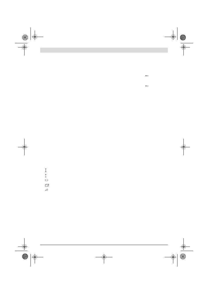
Eesti |
145
Bosch Power Tools
2 609 140 773 | (4.12.12)
Seadme osad
Seadme osade numeratsiooni aluseks on jooniste leheküljel
toodud numbrid.
1
Ekraan
2
Mõõtmise nupp
3
Pindala, ruumala ja kaudse kõrguse mõõtmise nupp (Py-
thagoras)
4
Kustutusnupp / lüliti (sisse/välja) **
5
Miinus-nupp
6
Lähtetasandi valiku nupp
7
Kanderihma kinnituskoht
8
Pluss-nupp
9
Pikkuse ja pideva mõõtmise nupp
10
Patareikorpuse kaas
11
Laserkiire väljundava
12
Vastuvõtulääts
13
Seerianumber
14
1/4"-keermega ava
15
Laseri hoiatussilt
16
Patareikorpuse kaane lukustus
17
Kaitsekott
18
Statiiv*
19
Laserkiire nähtavust parandavad prillid*
20
Laserkiire sihttahvel*
* Tarnekomplekt ei sisalda kõiki kasutusjuhendis olevatel joonistel
kujutatud või kasutusjuhendis nimetatud lisatarvikuid.
** Laiendatud funktsioonide käivitamiseks hoidke nuppu all.
Ekraani näidud
a
Mõõteväärtuste read
b
Tulemuse rida
c
Mõõterežiimid
d
Laser sisse lülitatud
e
Mõõtmise lähtetasand
f
Temperatuuri hoiatustuli
g
Patarei madala pinge indikaatortuli
h
Veateade
„ERROR“
Montaaž
Patareide paigaldamine/vahetamine
Mõõteseadmes on soovitav kasutada leelis-mangaan-patarei-
sid või akusid.
1,2-V-akudega on mõõtmiskordade arv väiksem kui 1,5-V-pa-
tareidega.
Patareikorpuse kaane
10
avamiseks vajutage lukustusele
16
ja tõmmake patareikorpuse kaas lahti. Asetage patareid või
akud kohale. Jälgige seejuures patareide õiget polaarsust
vastavalt patareikorpuse siseküljel toodud sümbolitele.
Patareide või akude sissepanekul jälgige patareide õiget po-
laarsust vastavalt patareikorpusel toodud joonisele.
Kui patarei madala pinge indikaatortuli
süttib ekraanil esi-
mest korda, saab teha veel vähemalt 100 mõõtmist. Pideva
mõõtmise funktsioon on välja lülitatud.
Kui patarei madala pinge indikaatortuli
vilgub, tuleb pata-
reid või akuelemendid välja vahetada. Mõõtmisi ei saa enam
teostada.
Vahetage alati välja kõik patareid või akud ühekorraga. Kasu-
tage üksnes ühe tootja ja ühesuguse mahtuvusega patareisid
või akusid.
Kui Te mõõteseadet pikemat aega ei kasuta, võtke pa-
tareid või akud seadmest välja.
Patareid ja akud võivad
pikemal seismisel korrodeeruda või iseeneslikult tühjene-
da.
Kasutamine
Kasutuselevõtt
Ärge jätke sisselülitatud seadet järelevalveta ja lüli-
tage seade pärast kasutamist välja.
Laserkiir võib teisi
inimesi pimestada.
Kaitske mõõteseadet niiskuse ja otsese päikese-
kiirguse eest.
Ärge hoidke mõõteseadet väga kõrgetel ja väga mada-
latel temperatuuridel, samuti vältige temperatuurikõi-
kumisi.
Ärge jätke seadet näiteks pikemaks ajaks autosse.
Suuremate temperatuurikõikumiste korral laske mõõte-
seadmel enne kasutuselevõttu keskkonna temperatuuriga
kohaneda. Äärmuslikel temperatuuridel ja temperatuuri-
kõikumiste korral võib seadme mõõtetäpsus väheneda.
Kaitske mõõteseadet tugevate löökide ja kukkumiste
eest.
Kui mõõteseadmele on avaldunud tugev väline me-
haaniline toime, tuleb enne töö jätkamist alati kontrollida
seadme täpsust (vt „Kauguse mõõtmise täpsuse kontrolli-
mine“, lk 147).
Sisse-/väljalülitus
Mõõteseadme
sisselülitamiseks
on järgmised võimalused:
– Vajutamine nupule (sisse/välja)
4
: Mõõteseade lülitub sis-
se ja on pikkuse mõõtmise režiimil. Laser ei lülitu sisse.
– Vajutamine mõõtmise nupule
2
: Mõõteseade ja laser lülitu-
vad sisse. Mõõteseade on pikkuse mõõtmise režiimil.
Ärge suunake laserkiirt inimeste ega loomade peale
ning ärge vaadake laserkiire poole ka mitte suurema
vahemaa tagant.
Seadme
väljalülitamiseks
vajutage pikalt nupule (sisse/ väl-
ja)
4
.
Kui umbes 5 minuti vältel ei ole vajutatud mõõteseadme ühe-
legi nupule, lülitub seade patareide säästmiseks automaatselt
välja.
Pikkuse mõõtmine
Pidev mõõtmine
Pindala mõõtmine
Ruumala mõõtmine
Ühekordne Pythagoras-mõõtmine
OBJ_BUCH-1444-004.book Page 145 Tuesday, December 4, 2012 1:47 PM
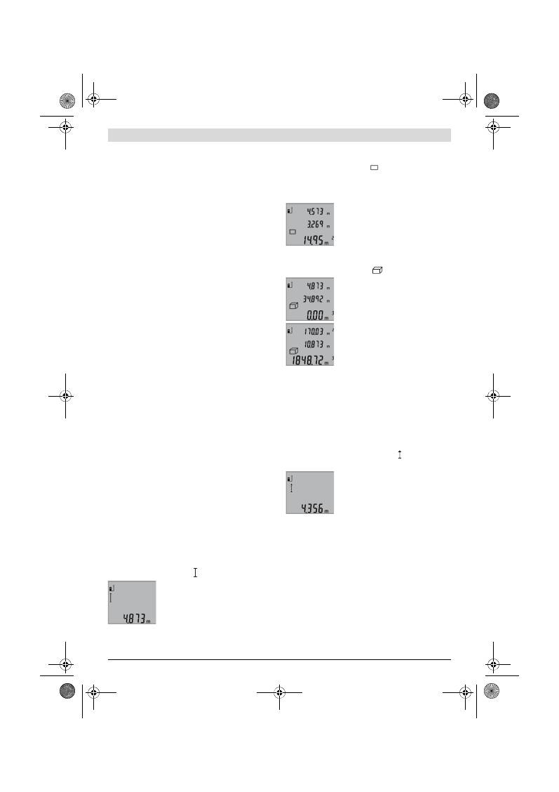
146
| Eesti
2 609 140 773 | (4.12.12)
Bosch Power Tools
Mõõtmine
Kui lülitasite mõõteseadme mõõtmise nupule
2
vajutamisega
sisse, on mõõteseade kogu aeg pikkuse mõõtmise režiimil.
Mõne muu mõõtefunktsiooni sisselülitamiseks tuleb vajutada
vastavale nupule (vt „Mõõterežiimid“, lk 146).
Mõõtmise lähtepunktiks on pärast sisselülitamist valitud mõõ-
teseadme tagaserv. Vajutades lähtetasandi nupule
6
, saate
lähtetasandit muuta (vt „Lähtetasandi valik“, lk 146).
Asetage mõõteseade valitud lähtetasandiga punkti, kust soo-
vite mõõtmist alustada (nt vastu seina).
Laserkiire sisselülitamiseks vajutage korraks mõõtmise nupu-
le
2
.
Ärge suunake laserkiirt inimeste ega loomade peale
ning ärge vaadake laserkiire poole ka mitte suurema
vahemaa tagant.
Viseerige laserkiirega välja sihtpind. Mõõtmisprotsessi käivi-
tamiseks vajutage uuesti korraks mõõtmise nupule
2
.
Pideva mõõtmise režiimis algab mõõtmine vahetult funktsioo-
ni sisselülitamisel.
Mõõtetulemus ilmub umbes 0,5 kuni 4 sekundi pärast. Mõõt-
mise kestus sõltub vahemaast, valgusoludest ja sihtpinna
peegeldusomadustest. Pärast mõõtmise lõpetamist lülitub la-
serkiir automaatselt välja.
Kui umbes 20 s pärast väljaviseerimist mõõtmist ei teostata,
lülitub laserkiir patareide säästmiseks automaatselt välja.
Lähtetasandi valik (vt joonist A)
Mõõtmise teostamiseks võite valida ühe kolmest erinevast
lähtetasandist:
– mõõteseadme tagaserv (nt vastu seina asetamisel),
– mõõteseadme esiserv (nt mõõtmisel alates lauaservast),
– keermega ava
14
keskpunkt (nt statiiviga tehtavate mõõt-
miste puhul).
Lähtetasandi valimiseks vajutage nupule
6
seni, kuni ekraani-
le ilmub soovitud lähtetasand. Pärast mõõteseadme sisselüli-
tamist on lähtetasandiks automaatselt mõõteseadme taga-
serv.
Ekraani valgustus
Ekraanivalgustus lülitub sõltuvalt ümbritseva keskkonna val-
gusoludest automaatselt sisse. Kui pärast ekraanivalgustuse
sisselülitamist ei vajutata ühelegi nupule, läheb ekraanival-
gustus patareide säästmiseks tuhmiks.
Mõõterežiimid
Pikkuse ühekordne mõõtmine (vt joonist B)
Pikkuse mõõtmiseks vajutage nupule
9
seni, kuni ekraanile il-
mub pikkuse mõõtmise sümbol .
Laseri sisselülitamiseks ja mõõtmiseks
vajutage korraks mõõtmise nupule
2
.
Mõõteväärtus ilmub tulemuse reale
b
.
Mitme üksteise järel tehtud pikkuse mõõt-
mise puhul ilmuvad viimaste mõõtmiste
tulemused mõõteväärtuste ridadele
a
.
Pindala mõõtmine (vt joonist C)
Pindala mõõtmiseks vajutage nupule
3
seni, kuni ekraanile il-
mub pindala mõõtmise sümbol
.
Seejärel mõõtke üksteise järel pikkus ja laius nagu pikkuse
mõõtmiselgi. Kahe mõõtmise vaheajal jääb laserkiir sisse-
lülitatuks.
Pärast teise mõõtmise teostamist arvuta-
takse pindala automaatselt välja ja kuva-
takse tulemuse real
b
. Üksikute mõõtmis-
te väärtused ilmuvad mõõteväärtuste ri-
dadele
a
.
Ruumala mõõtmine (vt joonist D)
Ruumala mõõtmiseks vajutage nupule
3
seni, kuni ekraanile il-
mub ruumala mõõtmise sümbol
.
Seejärel mõõtke üksteise järel pikkus,
laius ja kõrgus nagu pikkuse mõõtmiselgi.
Kolme mõõtmise vaheajal jääb laserkiir
sisselülitatuks.
Pärast kolmanda mõõtmise teostamist ar-
vutatakse ruumala automaatselt välja ja
see ilmub tulemuse reale
b
. Üksikute
mõõtmiste väärtused ilmuvad mõõte-
väärtuste ridadele
a
.
Väärtusi, mis on suuremad kui 999999 m
3
, ei ole võimalik ku-
vada, ekraanile ilmub
„ERROR“
. Leidke otsitav ruumala osa-
mõõtmiste teel ja liitke osamõõtmiste tulemused kokku.
Pidev mõõtmine (vt joonist E)
Pideval mõõtmisel võib mõõteseadet sihtobjekti suhtes liigu-
tada, kusjuures mõõteväärtust ajakohastatakse u. iga 0,5 s jä-
rel. Võite näiteks seinast kuni soovitud kauguseni eemalduda,
aktuaalne vahemaa ilmub pidevalt ekraanile.
Pideva mõõtmise teostamiseks vajutage nupule
9
seni, kuni
ekraanile ilmub pideva mõõtmise sümbol . Pideva mõõtmi-
se käivitamiseks vajutage mõõtmise nupule
2
.
Teostatava mõõtmise tulemus ilmub tule-
muse reale
b
.
Vajutamisega mõõtmise nupule
2
lõpeta-
te pideva mõõtmise. Viimane mõõteväär-
tus ilmub tulemuse reale
b
. Uus vajutami-
ne mõõtmise nupule
2
käivitab pideva
mõõtmise uuesti.
Pidev mõõtmine lülitub 5 minuti pärast automaatselt välja.
Viimane mõõteväärtus jääb tulemuse reale
b
.
Kaudne kõrguse mõõtmine / Ühekordne Pythagoras-
mõõtmine (vt joonist F)
Kaudset kõrguse mõõtmist kasutatakse vahemaade mõõtmi-
seks, mida ei saa mõõta otse, kuna laserkiire teel on mingi ta-
kistus või puudub peegeldav sihtpind. Korrektsed tulemused
saadakse ainult siis, kui mõõtmisel vajalikest täisnurkadest
peetakse täpselt kinni (Pythagorase teoreem).
Veenduge, et mõõtmise lähtepunkt (nt mõõteseadme taga-
serv) oleks kõikide üksikmõõtmiste ajal täpselt ühes ja samas
kohas.
Üksikute mõõtmiste vaheajal jääb laserkiir sisselülitatuks.
OBJ_BUCH-1444-004.book Page 146 Tuesday, December 4, 2012 1:47 PM
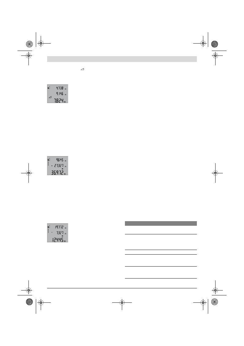
Eesti |
147
Bosch Power Tools
2 609 140 773 | (4.12.12)
Vajutage nupule
3
seni, kuni ekraanile ilmub ühekordse Pyt-
hagorase-mõõtmise sümbol
.
Mõõtke samamoodi nagu pikkuse mõõtmise puhul ära vahe-
maad
„1“
ja
„2“
samas järjekorras. Veenduge, et vahemaa
„1“
ja otsitud vahemaa
„X“
vahele jääb täisnurk.
Pärast viimase mõõtmise teostamist il-
mub otsitud vahemaa väärtus
„X“
tulemu-
se reale
b
. Üksikute mõõtmiste tulemu-
sed ilmuvad mõõteväärtuste ridadele
a
.
Mõõtmisväärtuste kustutamine
Vajutades korraks nupule
4
, saate kõikides mõõterežiimides
viimati väljaarvutatud üksiku mõõtmise tulemuse kustutada.
Kui vajutate nupule lühidalt mitu korda, kustutatakse üksikute
mõõtmiste tulemused vastupidises järjekorras.
Mõõteväärtuste liitmine
Mõõtetulemuste liitmiseks teostage kõigepealt mis tahes
mõõtmine. Seejärel vajutage pluss-nupule
8
. Ekraanile ilmub
kinnituseks
„+“
.
Ruumalade või pindalade liitmiseks vajutage pärast esimest
teostatud mõõtmist pluss-nupule
8
. Ekraanile ilmub kinnitu-
seks
„+“
, mis jääb ruumala-/pindalasümbolist vasakule.
Seejärel teostage teine mõõtmine.
Mõlema mõõtmise summa saamiseks va-
jutage veelkord pluss-nupule
8
. Arvutust
kuvatakse mõõteväärtuste ridadel
a
,
summa on tulemuse real
b
.
Pärast summa väljaarvutamist saab selle-
le juurde liita teisi mõõtetulemusi, kui en-
ne mõõtmist vajutada pluss-nupule
8
.
Juhiseid liitmiseks:
– Pikkusi, pindalasid ja ruumalasid ei saa läbisegi liita. Kui
näiteks pikkusele liita pindala, ilmub pluss-nupule
8
vajuta-
misel ekraanile korraks
„ERROR“
. Seejärel lülitub mõõte-
seade viimasesse aktiivsesse mõõterežiimi.
– Iga kord liidetakse juurde ühe mõõtmise tulemus (nt ruu-
mala), pideva mõõtmise puhul tulemuse real
b
kuvatud
väärtus. Mõõteväärtuste ridadel
a
olevaid üksikute mõõt-
miste tulemusi liita ei saa.
Mõõteväärtuste mahaarvamine
Mõõteväärtuste lahutamiseks vajutage
miinus-nupule
5
, ekraanile ilmub kinnitu-
seks
„–“
. Edasi toimige analoogiliselt
punktiga „Mõõteväärtuste liitmine“.
Tööjuhised
Üldised märkused
Vastuvõtulääts
12
ja laserkiire väljundava
11
ei tohi mõõtmi-
sel olla kinni kaetud.
Mõõteseadet ei tohi mõõtmise ajal liigutada (välja arvatud pi-
deva mõõtmise režiimis). Seetõttu asetage mõõteseade või-
maluse korral stabiilsele aluspinnale.
Mõõteulatust mõjutavad tegurid
Mõõteulatus sõltub valgusoludest ja sihtpinna peegeldusoma-
dustest. Välistingimustes ja tugeva päikesekiirguse käes
töötades kasutage laserkiire nähtavust parandavaid prille
19
(lisatarvik) ja laseri sihttahvlit
20
(lisatarvik) või varjutage
sihtpind.
Mõõtetulemust mõjutavad tegurid
Füüsikaliste tegurite tõttu ei saa välistada, et erinevate pinda-
de puhul ei esine mõõtmisel vigu. Selliste pindade hulka kuu-
luvad:
– läbipaistavad pinnad (nt klaas, vesi),
– peegelpinnad (nt poleeritud metall, klaas),
– poorsed pinnad (nt isolatsioonimaterjalid),
– struktureeritud pinnad (nt kare krohv, looduskivi).
Vajaduse korral kasutage sellistel pindadel laserkiire sihttahv-
lit
20
(lisatarvik).
Mõõtetulemused võivad olla lisaks ebaõiged ka kalde all välja-
fokuseeritud sihtpindade puhul.
Samuti võivad mõõtetulemust mõjutada erineva temperatuu-
riga õhukihid või kaudselt vastu võetud peegeldused.
Kauguse mõõtmise täpsuse kontrollimine
Kauguse mõõtmise täpsust saate kontrollida järgmiselt:
– Valige Teile teadaolev vahemaa pikkusega umbes 1 kuni
10 m (nt toa pikkus, ukseava laius), mille mõõt ei muutu.
Vahemaa peab olema siseruumis, mõõtmise sihtpind peab
olema sile ja hästi peegelduv.
– Mõõtke vahemaa 10 korda järjest.
Üksikute mõõtmiste kõrvalekalle keskmisest väärtusest tohib
olla kuni ±2 mm. Pange mõõtetulemused kirja, et täpsust va-
jaduse korral hiljem võrrelda.
Töö statiiviga (lisatarvik)
Statiivi kasutamine on vajalik eelkõige suuremate vahemaade
korral. Asetage mõõteseade 1/4"-keermestatud avaga
14
statiivi
18
või tavalise fotoaparaadi statiivi vahetatavale alu-
sele. Kinnitage see vahetatava aluse lukustuskruviga.
Nupule
6
vajutamisega reguleerige välja lähtetasand statiivi
abil teostatava mõõtmise jaoks (lähtetasandiks on keere).
Vead
–
põhjused ja kõrvaldamine
Põhjus
Vea kõrvaldamine
Temperatuuri hoiatustuli (f) vilgub, mõõtmist ei saa
teostada
Mõõteseadme temperatuur on väl-
jaspool lubatud vahemikku
– 10 °C kuni +50 °C (pideva
mõõtmise režiimis kuni +40 °C).
Oodake, kuni mõõte-
seade jõuab töötem-
peratuurivahemikku
Näit „ERROR“ ekraanil
Erinevate mõõtühikutega mõõte-
väärtuste liitmine/ lahutamine
Liitke/lahutage ainult
ühesuguste mõõtühi-
kutega mõõteväärtusi
Laserkiire ja sihtobjekti vaheline
nurk on liiga terav.
Suurendage laserkiire
ja sihtobjekti vahelist
nurka
OBJ_BUCH-1444-004.book Page 147 Tuesday, December 4, 2012 1:47 PM

148
| Latviešu
2 609 140 773 | (4.12.12)
Bosch Power Tools
Mõõteseade teostab järelevalvet iga mõõt-
mise korrektse toimimise üle. Häire tuvas-
tamisel vilgub ekraanil vaid kõrvaltoodud
sümbol. Sellisel juhul, samuti siis, kui ülal-
toodud abinõudega ei õnnestu viga kõrval-
dada, toimetage seade Boschi tööriistade
volitatud remonditöökotta.
Hooldus ja teenindus
Hooldus ja puhastus
Hoidke ja transportige seadet üksnes komplekti kuuluvas kait-
sekotis.
Hoidke mõõteseade alati puhas.
Ärge kastke mõõteseadet vette ega teistesse vedelikesse.
Pühkige seade puhtaks niiske, pehme lapiga. Ärge kasutage
puhastusvahendeid ega lahusteid.
Hooldage eelkõige vastuvõtuläätse
12
sama hoolikalt nagu
prille või fotoaparaadi läätse.
Mõõteseade on hoolikalt valmistatud ja testitud. Kui seade
sellest hoolimata rikki läheb, tuleb see lasta parandada Bosc-
hi elektriliste tööriistade volitatud remonditöökojas. Ärge
avage mõõteseadet ise.
Järelepärimiste esitamisel ja tagavaraosade tellimisel näida-
ke kindlasti ära seadme andmesildil olev 10-kohaline toote-
number.
Parandustöökotta toimetamisel asetage seade kaitsekotti
17
.
Klienditeenindus ja müügijärgne nõustamine
Klienditeeninduses vastatakse toote paranduse ja hoolduse
ning varuosade kohta esitatud küsimustele. Joonised ja teabe
varuosade kohta leiate ka veebisaidilt:
www.bosch-pt.com
Boschi nõustajad osutavad Teile toodete ja tarvikute küsimus-
tes meeleldi abi.
Eesti Vabariik
Mercantile Group AS
Boschi elektriliste käsitööriistade remont ja hooldus
Pärnu mnt. 549
76401 Saue vald, Laagri
Tel.: 679 1122
Faks: 679 1129
Kasutuskõlbmatuks muutunud seadmete käitlus
Mõõteseadmed, lisatarvikud ja pakendid tuleks keskkonna-
säästlikult ringlusse võtta.
Ärge käidelge mõõteseadmeid ja akusid/patareisid koos ol-
mejäätmetega!
Üksnes EL liikmesriikidele:
Vastavalt Euroopa Liidu direktiivile
2002/96/EÜ elektri- ja elektroonikasead-
mete jäätmete kohta ja vastavalt direktiivile
2006/66/EÜ tuleb kasutusressursi am-
mendanud mõõteseadmed ja defektsed või
kasutusressursi ammendanud akud/pata-
reid eraldi kokku koguda ja keskkonnasäästlikult korduskasu-
tada.
Tootja jätab endale õiguse muudatuste tegemiseks.
Latviešu
Drošības noteikumi
Lai varētu droši un netraucēti strādāt ar
mērinstrumentu, rūpīgi izlasiet un ievēro-
jiet visus šeit sniegtos norādījumus. Seko-
jiet, lai brīdinošās uzlīmes uz mērinstru-
menta būtu labi salasāmas. PĒC IZLASĪŠA-
NAS SAGLABĀJIET ŠOS NORĀDĪJUMUS.
Ievērībai! Veicot citas, nekā lietošanas pamācībā ap-
rakstītās apkalpošanas vai regulēšanas operācijas vai
rīkojoties ar mērinstrumentu lietošanas pamācībā ne-
paredzētā veidā, lietotājs var saņemt veselībai kaitīgu
starojuma devu.
Sihtpind peegeldab liiga tugevalt
(nt peegel) või liiga nõrgalt (nt
must kangas) või on ümbritsev val-
gus liiga tugev.
Kasutage laseri sihttahv-
lit
20
(lisatarvik)
Laserkiire väljundava
11
ja/või
vastuvõtulääts
12
on udused (nt
temperatuuri kiirest muutu-
misest).
Pehme lapiga hõõruge
laserkiire väljundava
11
ja/või vastuvõtulääts
12
kuivaks
Mõõdetud tulemus on suurem kui
999999 m/m
2
/m
3
.
Teostage mõõtmine
osamõõtmiste kaupa
Mõõtetulemus ei ole tõenäoline
Sihtpind ei peegelda korrektselt
(nt vesi, klaas).
Katke sihtpind kinni
Laserkiire väljundava
11
ja/või
vastuvõtulääts
12
on kinni kaetud.
Hoidke laserkiire väljun-
dava
11
ja/või
vastuvõtulääts
12
vabad
Valitud vale lähtetasand
Valige mõõtmise jaoks
kohane lähtetasand
Takistus laserkiire trajektooril
Laserpunkt peab olema
täielikult sihtpinnal.
Näit jääb samaks või mõõteseade reageerib nupule vaju-
tamisele mitteootuspäraselt
Tarkvaraviga
Eemaldage patareid ja
käivitage mõõteseade
pärast patareide tagasi-
panekut uuesti.
Põhjus
Vea kõrvaldamine
OBJ_BUCH-1444-004.book Page 148 Tuesday, December 4, 2012 1:47 PM

Latviešu |
149
Bosch Power Tools
2 609 140 773 | (4.12.12)
Mērinstruments tiek piegādāts kopā ar brīdinošu uzlī-
mi angļu valodā (grafikas lappusē parādītajā mērins-
trumenta attēlā tā ir apzīmēta ar numuru 15).
Uzsākot lietošanu, pārlīmējiet pāri angļu tekstam kopā
ar mērinstrumentu piegādāto brīdinošo uzlīmi jūsu
valsts valodā.
Nevērsiet lāzera staru citu personu vai mājdzīvnieku
virzienā un neskatieties lāzera starā.
Šis mērinstru-
ments izstrādā 2. klases lāzera starojumu atbilstoši stan-
dartam IEC 60825-1. Ar to var nejauši apžilbināt citas per-
sonas.
Nelietojiet lāzera skatbrilles kā aizsargbrilles.
Lāzera
skatbrilles kalpo, lai uzlabotu lāzera stara redzamību, taču
tās nespēj pasargāt no lāzera starojuma.
Nelietojiet lāzera skatbrilles kā saulesbrilles un kā
aizsargbrilles, vadot satiksmes līdzekļus.
Lāzera skat-
brilles nenodrošina pilnvērtīgu redzes aizsardzību no ultra-
violetā starojuma, taču pasliktina krāsu izšķirtspēju.
Nodrošiniet, lai mērinstrumentu remontētu tikai kvali-
ficēts speciālists, nomaiņai izmantojot vienīgi oriģinā-
lās rezerves daļas.
Tas ļaus saglabāt vajadzīgo darba dro-
šības līmeni, strādājot ar mērinstrumentu.
Neļaujiet bērniem lietot lāzera mērinstrumentu bez uz-
raudzības.
Viņi var nejauši apžilbināt citas personas.
Nestrādājiet ar mērinstrumentu sprādzienbīstamās
vietās, kur atrodas viegli degoši šķidrumi, gāzes vai pu-
tekļi.
Mērinstrumentā var rasties dzirksteles, kas var izrai-
sīt putekļu vai tvaiku aizdegšanos.
Izstrādājuma un tā darbības apraksts
Atveriet atlokāmo lapu ar mērinstrumenta attēlu un turiet to
atvērtu visu laiku, kamēr tiek lasīta lietošanas pamācība.
Pielietojums
Mērinstruments ir paredzēts attāluma (garuma) un augstuma
mērīšanai, kā arī laukuma un tilpuma aprēķināšanai. Tas ir pie-
mērots darbam telpās un ārpus telpām.
Tehniskie parametri
Digitālais lāzera tālmērs
GLM 50
Professional
Izstrādājuma numurs
3 601 K72 2..
Mērīšanas diapazons
0,05 –50 m
A)
Mērīšanas precizitāte (tipiskā vērtība)
±1,5 mm
B)
Mazākā mērījumu indikācijas vienība
1 mm
Darba temperatūra
–10 °C...+50 °C
C)
Uzglabāšanas temperatūra
–20 °C...+70 °C
Maks. relatīvais gaisa mitrums
90 %
Lāzera klase
2
Lāzera starojums
635 nm, <1 mW
Lāzera stara diametrs (pie 25 °C) apt.
– 10 m attālumā
– 50 m attālumā
6 mm
35 mm
Automātiskā izslēgšanās pēc apt.
– lāzeram
– mērinstrumentam (ja nenotiek mērījumi)
20 s
5 min.
Baterijas
Akumulatori
2 x 1,5 V LR03 (AAA)
2 x 1,2 V HR03 (AAA)
Bateriju darbības laiks, apt.
– atsevišķiem mērījumiem
– mērot nepārtrauktā režīmā
10000
D)
2,5 st.
D)
Svars atbilstoši EPTA-Procedure 01/2003
0,14 kg
Izmēri
53 x 114 x 30 mm
Aizsardzības tips
IP 54 (aizsargāts pret lietu un ūdens šļakatām)
OBJ_BUCH-1444-004.book Page 149 Tuesday, December 4, 2012 1:47 PM
150
| Latviešu
2 609 140 773 | (4.12.12)
Bosch Power Tools
Attēlotās sastāvdaļas
Attēloto sastāvdaļu numerācija sakrīt ar numuriem mērinstru-
menta attēlā, kas sniegts grafiskajā lappusē.
1
Displejs
2
Mērīšanas taustiņš
3
Taustiņš laukuma un tilpuma mērīšanai un augstuma ne-
tiešajai mērīšanai (izmantojot Pitagora teorēmu)
4
Taustiņš atmiņas satura dzēšanai / ieslēgšanai un izslēg-
šanai **
5
Mīnus taustiņš
6
Taustiņš nulles līmeņa izvēlei
7
Siksniņas stiprinājums
8
Plus taustiņš
9
Taustiņš attāluma (garuma) mērīšanai un mērīšanai ne-
pārtrauktā režīmā
10
Bateriju nodalījuma vāciņš
11
Lāzera starojuma izvadlūka
12
Starojuma uztvērēja lēca
13
Sērijas numurs
14
1/4" vītne
15
Brīdinošā uzlīme
16
Baterijas nodalījuma vāciņa fiksators
17
Aizsargsoma
18
Statīvs*
19
Lāzera skatbrilles*
20
Lāzera mērķplāksne*
* Attēlotie vai aprakstītie piederumi neietilpst standarta piegādes
komplektā.
** Lai izsauktu paplašinātās funkcijas, turiet taustiņu nospiestu.
Indikācijas elementi
a
Starprezultātu indikatori
b
Rezultātu indikators
c
Mērīšanas režīmu apzīmējumi
d
Lāzera ieslēgšanas indikators
e
Nulles līmeņa indikators
f
Temperatūras brīdinājuma indikators
g
Baterijas nolietošanās indikators
h
Kļūmes indikators
„ERROR“
Montāža
Bateriju ievietošana/nomaiņa
Mērinstrumenta darbināšanai ieteicams izmantot sārma-
mangāna baterijas vai akumulatorus.
Izmantojot 1,2 V akumulatorus, iespējamo mērījumu skaits ir
mazāks, nekā ar 1,5 V baterijām.
Lai atvērtu bateriju nodalījuma vāciņu
10
, nospiediet fiksato-
ru
16
un noņemiet vāciņu. Ievietojiet bateriju nodalījumā ba-
terijas vai akumulatorus. Ievērojiet pareizu pievienošanas po-
laritāti, kas attēlota bateriju nodalījuma iekšpusē.
Ievietojot baterijas vai akumulatorus, ievērojiet pareizu pie-
vienošanas polaritāti, kas parādīta bateriju nodalījumā.
Ja uz displeja pirmo reizi parādās baterijas simbols
, tas
norāda, ka baterijas spēj nodrošināt vēl vismaz 100 mērīju-
mus. Taču šādā gadījumā tiek deaktivizēta nepārtrauktās mē-
rīšanas funkcija.
Ja baterijas simbols
mirgo, tas norāda, ka baterijas vai
akumulatorus nepieciešams nomainīt. Šādā gadījumā mērīša-
na vairs nav iespējama.
Vienmēr vienlaicīgi nomainiet visas baterijas vai akumulato-
rus. Izmantojiet tikai vienādas ietilpības baterijas vai akumula-
torus, kas pagatavoti vienā ražotājfirmā.
Ja mērinstruments ilgāku laiku netiek lietots, izņemiet
no tā baterijas vai akumulatorus.
Ilgstoši uzglabājot mē-
rinstrumentu, tajā ievietotās baterijas vai akumulatori var
korodēt un izlādēties.
Lietošana
Uzsākot lietošanu
Neatstājiet ieslēgtu mērinstrumentu bez uzraudzības
un pēc lietošanas to izslēdziet.
Lāzera stars var apžilbi-
nāt citas tuvumā esošās personas.
Sargājiet mērinstrumentu no mitruma un saules staru
tiešas iedarbības.
Nepakļaujiet instrumentu ļoti augstas vai ļoti zemas
temperatūras iedarbībai un straujām temperatūras iz-
maiņām.
Piemēram, neatstājiet mērinstrumentu uz ilgāku
laiku automašīnā. Pie straujām temperatūras izmaiņām
vispirms nogaidiet, līdz izlīdzinās temperatūras starpība,
A) Mērinstrumenta darbības tālums ir jo lielāks, jo lāzera starojums tiek labāk atstarots no mērķa virsmas (izkliedētā veidā, bez tiešas atspoguļošanās)
un jo spožāks ir lāzera stara projekcijas punkts attiecībā pret apkārtējo fona apgaismojumu (strādājot telpās vai mijkrēslī). Nelabvēlīgos darba apstākļos
(piemēram, veicot mērījumus ārpus telpām spožā saules gaismā) var būt nepieciešams izmantot mērķplāksni.
B) Veicot mērīšanu no mērinstrumenta aizmugurējās malas. Nelabvēlīgos darba apstākļos, piemēram, spožā saules gaismā vai slikti atstarojošu virsmu
gadījumā maksimālā kļūda ir
±
10 mm 50 m attālumā. Labvēlīgos darba apstākļos var rēķināties ar iespējamo kļūdu
±
0,05 mm/m.
C) Nepārtrauktās mērīšanas režīmā maksimālā darba temperatūra ir +40
°C
.
D) Izmantojot 1,2 V akumulatorus, iespējamo mērījumu skaits ir mazāks, nekā ar 1,5 V baterijām. Šeit sniegtie dati par bateriju darbības laiku ir spēkā,
ja mērīšana notiek bez displeja apgaismojuma.
Mērinstrumenta viennozīmīgai identifikācijai kalpo sērijas numurs
13
, kas atrodams uz marķējuma plāksnītes.
Attāluma (garuma) mērīšana
Mērīšana nepārtrauktā režīmā
Laukuma mērīšana
Tilpuma mērīšana
Vienkārša netiešā mērīšana
OBJ_BUCH-1444-004.book Page 150 Tuesday, December 4, 2012 1:47 PM

Latviešu |
151
Bosch Power Tools
2 609 140 773 | (4.12.12)
un tikai pēc tam uzsāciet mērinstrumenta lietošanu. Eks-
tremālu temperatūras vērtību vai strauju temperatūras iz-
maiņu iedarbība uz mērinstrumentu var nelabvēlīgi ietek-
mēt tā precizitāti.
Sargājiet mērinstrumentu no spēcīgiem triecieniem,
neļaujiet tam krist.
Ja mērinstruments ir saņēmis stipru
triecienu, pirms darba turpināšanas vienmēr jāpārbauda tā
precizitāte (skatīt sadaļu „Mērinstrumenta precizitātes
pārbaude attāluma mērīšanas režīmam“ lappusē 153).
Ieslēgšana un izslēgšana
Lai
ieslēgtu
mērinstrumentu, pastāv šādas iespējas.
– Nospiediet ieslēgšanas/izslēgšanas taustiņu
4
: mērinstru-
ments ieslēdzas un pāriet garuma mērīšanas režīmā. Šajā
laikā lāzera stars neieslēdzas.
– Nospiediet mērīšanas taustiņu
2
: ieslēdzas mērinstru-
ments un lāzera stars. Mērinstruments pāriet garuma mērī-
šanas režīmā.
Nevērsiet lāzera staru citu personu vai mājdzīvnieku
virzienā un neskatieties lāzera starā pat no liela attālu-
ma.
Lai
izslēgtu
mērinstrumentu, ilgstoši nospiediet ieslēgšanas/
izslēgšanas taustiņu
4
.
Ja aptuveni 5 minūtes netiek nospiests neviens no mērinstru-
menta taustiņiem, mērinstruments automātiski izslēdzas, šā-
di taupot baterijas.
Mērīšana
Ja mērinstruments tiek ieslēgts, nospiežot mērīšanas tausti-
ņu
2
, tas vienmēr pāriet garuma mērīšanas režīmā. Pāreja ci-
tos mērīšanas režīmos notiek, nospiežot attiecīgā režīma izvē-
les taustiņu (skatīt sadaļu „Mērīšanas veidi“ lappusē 151).
Pēc ieslēgšanas kā mērījumu nulles līmenis tiek automātiski
izvēlēta mērinstrumenta aizmugurējā mala. Nospiežot nulles
līmeņa izvēles taustiņu
6
, var izmainīt mērinstrumenta nulles
līmeni (skatīt sadaļu „Nulles līmeņa izvēle“ lappusē 151).
Novietojiet mērinstrumentu tā, lai izvēlētais nulles līmenis sa-
kristu ar vēlamo mērījumu sākuma punktu (piemēram, ar sie-
nu).
Lai ieslēgtu lāzera staru, īslaicīgi nospiediet mērīšanas tausti-
ņu
2
.
Nevērsiet lāzera staru citu personu vai mājdzīvnieku
virzienā un neskatieties lāzera starā pat no liela attālu-
ma.
Vērsiet lāzera staru uz mērķa virsmu un to izgaismojiet. Lai
veiktu mērīšanu, vēlreiz īslaicīgi nospiediet mērīšanas tausti-
ņu
2
.
Nepārtrauktās mērīšanas režīmā mērīšana sākas uzreiz pēc šī
režīma ieslēgšanas.
Mērījuma rezultāts parasti tiek parādīts uz displeja pēc 0,5 se-
kundēm, taču ne vēlāk, kā pēc 4 sekundēm. Mērījuma ilgums
ir atkarīgs no attāluma, apgaismojuma apstākļiem un mērķa
virsmas atstarojošajām īpašībām. Pēc mērījuma pabeigšanas
lāzera stars automātiski izslēdzas.
Ja pēc mērķa virsmas izgaismošanas mērījums netiek veikts,
lāzera stars automātiski izslēdzas aptuveni pēc 20 sekundēm,
šādi taupot baterijas.
Nulles līmeņa izvēle (attēls A)
Mērījumiem var izvēlēties vienu no trim nulles līmeņiem:
– mērinstrumenta aizmugurējo malu (piemēram, piespiežot
mērinstrumentu pie sienas),
– mērinstrumenta priekšējo malu (piemēram, veicot mērīša-
nu no galda malas),
– vītnes
14
vidu (piemēram, veicot mērīšanu ar statīvu).
Lai izvēlētos nulles līmeni, atkārtoti nospiediet taustiņu
6
, līdz
uz displeja parādās vēlamā nulles līmeņa apzīmējums. Ik reizi
pēc mērinstrumenta ieslēgšanas kā nulles līmenis tiek auto-
mātiski izvēlēta mērinstrumenta aizmugurējā mala.
Displeja apgaismojums
Displeja apgaismojums automātiski aktivizējas atbilstoši ap-
gaismojuma apstākļiem mērīšanas vietā. Ja pēc displeja ap-
gaismojuma ieslēgšanās netiek nospiests neviens taustiņš,
tas tiek pietumšots, šādi taupot baterijas.
Mērīšanas veidi
Vienkārša attāluma (garuma) mērīšana (attēls B)
Lai izmērītu attālumu (garumu), atkārtoti nospiediet taustiņu
9
, līdz uz displeja parādās garuma mērīšanas apzīmējums .
Lai ieslēgtu lāzeru, īslaicīgi nospiediet
mērīšanas taustiņu
2
un tad to nospiediet
vēlreiz, lai veiktu mērījumu.
Izmērītā vērtība tiek parādīta rezultātu in-
dikatorā
b
.
Ja pēc kārtas tiek izdarīti vairāki attāluma (garuma) mērījumi,
pēdējo mērījumu rezultāti tiek parādīti starprezultātu indika-
toros
a
.
Laukuma mērīšana (attēls C)
Lai izmērītu laukumu, atkārtoti nospiediet taustiņu
3
, līdz uz
displeja parādās laukuma mērīšanas apzīmējums .
Secīgi veiciet mērāmā laukuma garuma un platuma mērīju-
mus, rīkojoties līdzīgi, kā attāluma mērīšanas gadījumā. Laikā
starp šiem mērījumiem lāzera stars paliek ieslēgts.
Pēc otrā mērījuma beigām laukuma mērī-
juma rezultāts tiek automātiski aprēķināts
un parādīts rezultātu indikatorā
b
. Atse-
višķo mērījumu rezultāti tiek parādīti
starprezultātu indikatoros
a
.
Tilpuma mērīšana (attēls D)
Lai izmērītu tilpumu, atkārtoti nospiediet taustiņu
3
, līdz uz
displeja parādās tilpuma mērīšanas apzīmējums .
Secīgi veiciet mērāmā tilpuma garuma,
platuma un augstuma mērījumus, rīkojo-
ties līdzīgi, kā attāluma mērīšanas gadīju-
mā. Laikā starp šiem mērījumiem lāzera
stars paliek ieslēgts.
Pēc trešā mērījuma beigām tilpuma mērī-
juma rezultāts tiek automātiski aprēķināts
un parādīts rezultātu indikatorā
b
. Atse-
višķo mērījumu rezultāti tiek parādīti
starprezultātu indikatoros
a
.
OBJ_BUCH-1444-004.book Page 151 Tuesday, December 4, 2012 1:47 PM
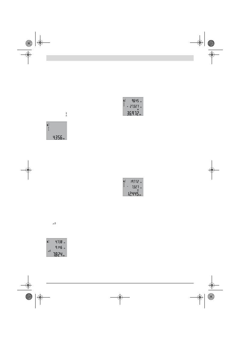
152
| Latviešu
2 609 140 773 | (4.12.12)
Bosch Power Tools
Vērtības, kas lielākas par 999999 m
3
, nevar tikt parādītas,
tāpēc uz displeja parādās kļūmes indikators
„ERROR“
. Šādā
gadījumā sadaliet mērāmo tilpumu vairākās daļās, atsevišķi
izmēriet šo daļu tilpumu un tad summējiet iegūtās tilpuma vēr-
tības.
Ilgstoša mērīšana (attēls E)
Veicot mērīšanu nepārtrauktā režīmā, mērinstrumentu var
pārvietot attiecībā pret mērķi, pie tam izmērītā vērtība tiek at-
jaunota aptuveni ik pēc 0,5 sekundēm. Piemēram, lietotājs
var attālināties no sienas, nepārtraukti nolasot savu attālumu
līdz tai, līdz tiek sasniegts vēlamais attālums.
Lai pārietu uz mērīšanu nepārtrauktā režīmā, atkārtoti nospie-
diet taustiņu
9
, līdz uz displeja parādās nepārtrauktās mērīša-
nas apzīmējums . Lai uzsāktu mērīšanu nepārtrauktā režī-
mā, nospiediet mērīšanas taustiņu
2
.
Aktuālā izmērītā vērtība tiek parādīta re-
zultātu indikatorā
b
.
Lai izbeigtu mērīšanu nepārtrauktā režī-
mā, nospiediet mērīšanas taustiņu
2
. Pē-
dējā izmērītā vērtība tiek parādīta rezultā-
tu indikatorā
b
. Lai atsāktu mērīšanu ne-
pārtrauktā režīmā, vēlreiz nospiediet mērīšanas taustiņu
2
.
Mērīšana nepārtrauktā režīmā automātiski izbeidzas pēc
5 minūtēm. Pēdējā izmērītā vērtība tiek parādīta rezultātu in-
dikatorā
b
.
Augstuma netiešā mērīšana / Vienkārša netiešā mērīšana
(attēls F)
Pielietojot augstuma netiešo mērīšanu, var noteikt augstumu,
ko nevar izmērīt tieši, piemēram, ja stara izplatīšanos traucē
šķēršļi vai arī nav tādas mērķa virsmas, kas varētu atstarot lā-
zera staru. Šādi mērījumi ļauj iegūt pareizus rezultātus vienīgi
tad, ja attiecīgā mērījuma laikā tiek precīzi ieturēts taisns leņ-
ķis (metodes pamatā ir Pitagora teorēma).
Sekojiet, lai katras mērīšanas operācijas laikā visi atsevišķie
mērījumi tiktu veikti ar vienu un to pašu nulles līmeni (piemē-
ram, no mērinstrumenta aizmugurējās malas) un tas atrastos
precīzi vienā un tajā pašā vietā.
Laikā starp atsevišķajiem mērījumiem lāzera stars paliek ie-
slēgts.
Atkārtoti nospiediet mērīšanas režīma izvēles taustiņu
3
, līdz
uz displeja parādās vienkāršas netiešās mērīšanas apzīmē-
jums .
Izmēriet nogriežņu
„1“
un
„2“
garumu norādītajā secībā. Se-
kojiet, lai starp nogriezni
„1“
un mērāmo augstumu
„X“
sagla-
bātos taisns leņķis.
Pēc pēdējā mērījuma beigām augstuma
„X“
vērtība tiek parādīta rezultātu indika-
torā
b
. Atsevišķo mērījumu rezultāti tiek
parādīti starprezultātu indikatoros
a
.
Izmērīto vērtību dzēšana
Īslaicīgi nospiežot taustiņu
4
, var izdzēst pēdējo izmērīto vēr-
tību, kas noteikta jebkurā mērīšanas režīmā. Vairākkārt īslaicī-
gi nospiežot šo taustiņu, atsevišķās izmērītās vērtības pēc
kārtas tiek dzēsti secībā, kas pretēja mērījumu izdarīšanas se-
cībai.
Izmērīto vērtību saskaitīšana
Lai saskaitītu izmērītās vērtības, vispirms veiciet jebkura vei-
da mērījumu. Tad nospiediet plus taustiņu
8
. Apstiprinot šo
operāciju, uz displeja parādās apzīmējums
„+“
.
Lai saskaitītu tilpuma vai laukuma vērtības, pēc pirmā mērīju-
ma pabeigšanas nospiediet plus taustiņu
8
. Apstiprinot šo
operāciju, uz displeja parādās apzīmējums
„+“
pa kreisi no til-
puma vai laukuma mērīšanas apzīmējuma.
Tad veiciet otrās vērtības mērīšanu.
Lai nolasītu abu izmērīto vērtību summu,
vēlreiz nospiediet plus taustiņu
8
. Aprēķi-
nam izmantotās vērtības tiek parādītas
starprezultātu indikatoros
a
, bet aprēķi-
nātā summa tiek parādīta rezultātu indi-
katorā
b
.
Pēc rezultāta aprēķināšanas tam var pieskaitīt citas izmērītās
vērtības, ja ik reizi pirms mērīšanas tiek nospiests plus taus-
tiņš
8
.
Norādījumi par saskaitīšanu.
– Attāluma (garuma), laukuma un tilpuma vērtības nav ie-
spējams saskaitīt jauktā veidā. Piemēram, mēģinot pie-
skaitīt garuma vērtībai laukuma vērtību, pēc plus taustiņa
8
nospiešanas uz displeja īslaicīgi parādās kļūmes ziņojums
„ERROR“
. Pēc tam mērinstruments pāriet pēdējo reizi iz-
mantotajā mērīšanas režīmā.
– Vienmēr tiek pieskaitīta izmērītā vērtība (piemēram, tilpu-
ma vērtība), kas saskaitīšanas brīdī ir redzama rezultātu in-
dikatorā
b
. Starprezultātu indikatoros parādīto atsevišķo
mērījumu vērtību pieskaitīšana
a
nav iespējama.
Izmērīto vērtību atņemšana
Lai veiktu izmērīto vērtību atņemšanu,
nospiediet mīnus taustiņu
5
; apstiprinot
šo operāciju, uz displeja parādās apzīmē-
jums
„–“
. Citas darbības ir analogas tām,
kas aprakstītas sadaļā „Izmērīto vērtību
saskaitīšana“.
Norādījumi darbam
Vispārēji norādījumi
Starojuma uztvērēja lēca
12
un lāzera stara izvadlūka
11
mērīšanas laikā nedrīkst būt aizsegta.
Mērīšanas laikā mērinstrumentu nedrīkst pārvietot (izņemot
gadījumus, kad mērījumi tiek veikti nepārtrauktās mērīšanas
režīmā). Tāpēc, ja iespējams, mērīšanas laikā piespiediet mē-
rinstrumentu pie stingras atdures vai novietojiet uz stabilas
virsmas.
Ārējo faktoru ietekme uz mērīšanas tālumu
Mērīšanas tālums ir atkarīgs no apgaismojuma apstākļiem un
mērķa virsmas atstarošanas īpašībām. Lai uzlabotu lāzera sta-
ra redzamību ārpus telpām un jo īpaši spožā saules gaismā,
lietojiet lāzera skatbrilles
19
(papildpiederums) un lāzera
mērķplāksni
20
(papildpiederums) vai arī nosedziet (aizēno-
jiet) mērķa virsmu.
OBJ_BUCH-1444-004.book Page 152 Tuesday, December 4, 2012 1:47 PM
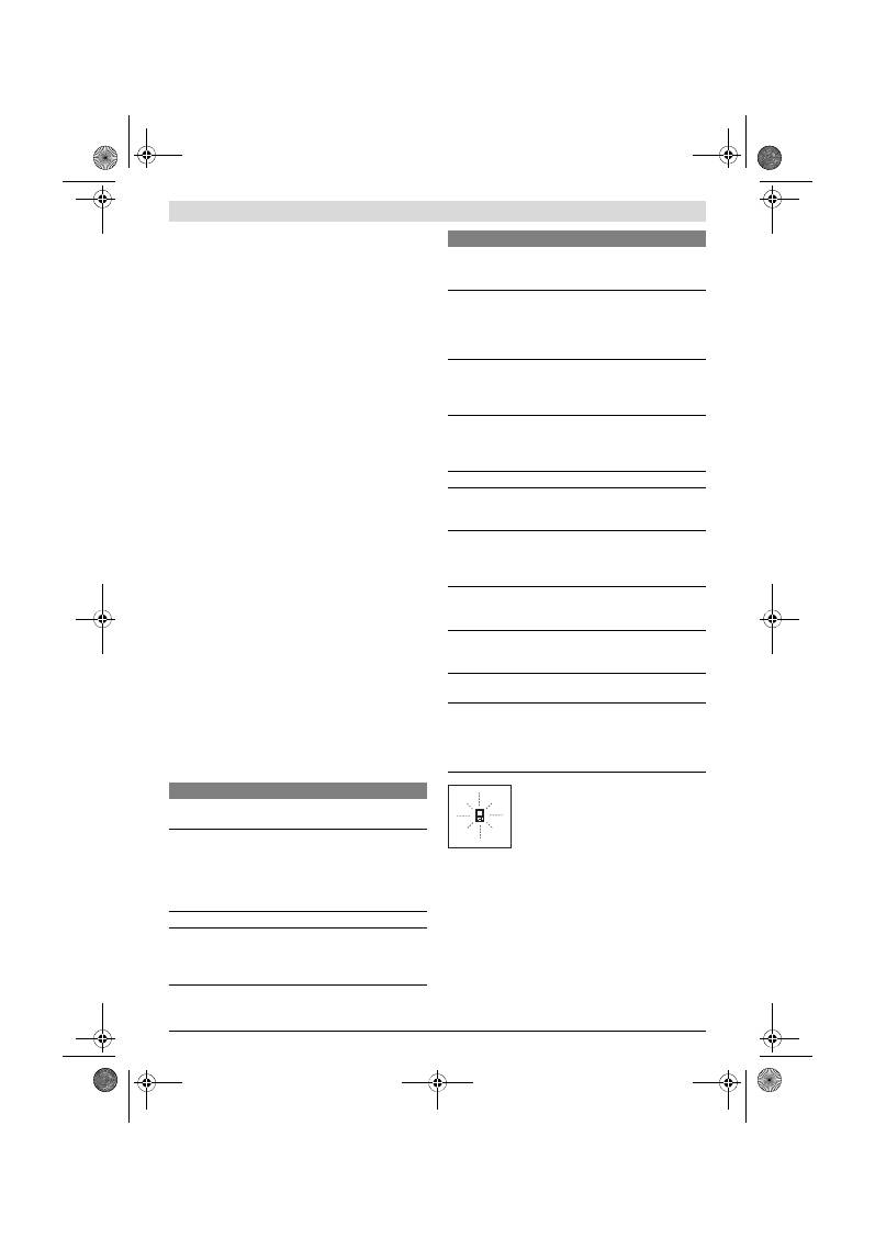
Latviešu |
153
Bosch Power Tools
2 609 140 773 | (4.12.12)
Ārējo faktoru ietekme uz mērījumu rezultātiem
Noteiktu fizikālu efektu dēļ attālumu noteikšanas laikā līdz da-
žu veidu virsmām var rasties ievērojamas mērījumu kļūdas.
Pie šādām virsmām pieder:
– caurspīdīgas virsmas (piemēram, stikls vai ūdens virsma),
– atstarojošas virsmas (piemēram, pulēts metāls vai stikls),
– porainas virsmas (piemēram, matēti materiāli) un
– strukturētas virsmas (piemēram, raupjš apmetums vai da-
biskais akmens).
Ja nepieciešams, novietojiet uz šādām virsmām lāzera mērķ-
plāksni
20
(papildpiederums).
Mērījumu kļūdas bieži rodas, izvēloties un iezīmējot slīpas
mērķa virsmas.
Līdzīgā veidā mērījumu rezultātus var ietekmēt gaisa slāņi ar
atšķirīgu temperatūru vai arī netiešo atstarojumu nonākšana
starojuma uztvērējā.
Mērinstrumenta precizitātes pārbaude attāluma mērīša-
nas režīmam
Mērinstrumenta precizitāti attāluma mērīšanas režīmam var
pārbaudīt šādi.
– Izvēlieties attālumu robežās aptuveni no 1 līdz 10 m, kura
vērtība ir pastāvīga un labi zināma (piemēram, istabas vai
durvju ailes platums). Mērāmajam attālumam jāatrodas
telpās, mērķa virsmai jābūt gludai un labi atstarojošai.
– Izmēriet šo attālumu 10 reizes pēc kārtas.
Atsevišķo mērījumu vērtību atšķirība no to vidējās vērtības
nedrīkst pārsniegt ±2 mm. Pierakstiet un uzglabājiet šo mērī-
jumu rezultātus, lai vēlāk varētu salīdzināt mērinstrumenta
precizitāti.
Darbs ar statīvu (papildpiederums)
Statīvs ir īpaši noderīgs tad, ja mērīšana notiek lielā attālumā.
Izmantojot mērinstrumenta 1/4" vītni
14
, nostipriniet to uz
statīva
18
ātri nomaināmās plāksnes vai arī uz parastā foto-
statīva, ko var iegādāties tirdzniecības vietās. Ar stiprinošo
skrūvi stingri nostipriniet ātri nomaināmo plāksni uz statīva.
Nospiežot taustiņu
6
, izvēlieties atskaites līmeni mērīšanai ar
statīvu (šajā gadījumā par atskaites līmeni kalpo vītne).
Kļūmes un to novēršana
Ikviena mērījuma laikā tiek kontrolēta
mērinstrumenta pareiza funkcionēšana. Ja
mērinstrumenta paškontroles sistēma at-
klāj defektu, uz displeja sāk mirgot šeit
parādītais simbols. Šādā gadījumā, kā arī
tad, ja iepriekš aplūkotie pasākumi ne-
sniedz vēlamo rezultātu, griezieties tuvākajā specializētajā
tirdzniecības vietā, lai nosūtītu mērinstrumentu uz Bosch piln-
varotu klientu apkalpošanas iestādi.
Apkalpošana un apkope
Apkalpošana un tīrīšana
Uzglabāšanas un transportēšanas laikā ievietojiet mērinstru-
mentu kopā ar to piegādātajā aizsargsomā.
Uzturiet mērinstrumentu tīru.
Neiegremdējiet mērinstrumentu ūdenī vai citos šķidrumos.
Kļūmes cēlonis
Novēršana
Temperatūras brīdinājuma indikators (f) mirgo, mērīša-
na nav iespējama
Mērinstrumenta temperatūra ir ār-
pus pieļaujamo darba temperatū-
ras vērtību diapazona, kas ir no
– 10 °C līdz +50 °C (nepārtrauk-
tās mērīšanas režīmā līdz
+40 °C).
Nogaidiet, līdz mēr-
instrumenta tem-
peratūra sasniedz
pieļaujamo darba tem-
peratūras vērtību diapa-
zonu
Uz displeja ir redzams kļūmes indikators „ERROR“
Ir noticis mēģinājums saskaitīt vai
atņemt izmērītās vērtības ar dažā-
dām mērvienībām
Saskaitiet vai atņemiet
tikai izmērītās vērtības
ar vienādām mēr-
vienībām
Leņķis starp lāzera staru un mērķa
virsmu ir pārāk šaurs.
Palieliniet leņķi starp lā-
zera staru un mērķa virs-
mu
Mērķa virsma atstaro pārāk spēcī-
gi (piemēram, spogulis) vai pārāk
vāji (piemēram, melns audums),
vai arī ir pārāk spēcīgs apkārtējais
apgaismojums.
Lietojiet lāzera mērķp-
lāksni
20
(papild-
piederums)
Lāzera stara izvadlūka
11
un/vai
starojuma uztvērēja lēca
12
ir aiz-
svīdusi (piemēram, strauju
temperatūras izmaiņu rezultātā).
Ar mīkstu audumu ap-
slaukiet lāzera stara iz-
vadlūku
11
un/vai staro-
juma uztvērēja lēcu
12
Izmērītā vērtība ir lielāka par
999999 m/m
2
/m
3
.
Sadaliet mērāmo lielu-
mu vairākās daļās un vei-
ciet mērīšanu vairākos
paņēmienos
Mērījumu rezultāti nav ticami
Atstarojums no mērķa virsmas ir
nevienmērīgs (piemēram, no
ūdens virsmas vai stikla).
Nosedziet (aizēnojiet)
mērķa virsmu
Lāzera stara izvadlūka
11
un/vai
starojuma uztvērēja lēca
12
ir aiz-
segta.
Atsedziet lāzera stara
izvadlūku
11
un/vai
starojuma uztvērēja lēcu
12
Ir nepareizi izvēlēts mērījumu nul-
les līmenis
Izvēlieties nulles līmeni,
kas atbilst mērīšanas
apstākļiem
Lāzera stara ceļā ir šķēršļi
Lāzera stara projekcijas
punktam pilnībā jāatro-
das uz mērķa virsmas.
Indikatoru rādījumi nemainās vai arī mērinstruments ne-
parasti reaģē uz taustiņu nospiešanu
Kļūme programmatūrā
Uz laiku izņemiet no mē-
rinstrumenta baterijas
un pēc to ievietošanas
no jauna ieslēdziet mē-
rinstrumentu.
Kļūmes cēlonis
Novēršana
OBJ_BUCH-1444-004.book Page 153 Tuesday, December 4, 2012 1:47 PM
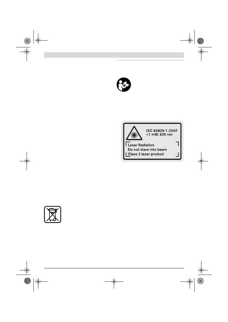
154
| Lietuviškai
2 609 140 773 | (4.12.12)
Bosch Power Tools
Apslaukiet izstrādājumu ar mitru, mīkstu lupatiņu. Nelietojiet
apkopei ķīmiski aktīvus tīrīšanas līdzekļus vai organiskos šķī-
dinātājus.
Saudzīgi apejieties ar starojuma uztvērēja lēcu
12
un apko-
piet to tikpat rūpīgi, kā briļļu lēcas vai fotoaparāta objektīvu.
Ja, neraugoties uz augsto izgatavošanas kvalitāti un rūpīgo
pēcražošanas pārbaudi, mērinstruments tomēr sabojājas, tas
jāremontē Bosch pilnvarotā elektroinstrumentu remonta
darbnīcā. Neatveriet mērinstrumentu saviem spēkiem.
Pieprasot konsultācijas un nomainot rezerves daļas, lūdzam
noteikti norādīt 10 zīmju izstrādājuma numuru, kas atrodams
uz mērinstrumenta marķējuma plāksnītes.
Nosūtot mērinstrumentu remontam, ievietojiet to aizsarg-
somā
17
.
Klientu konsultāciju dienests un konsultācijas
par lietošanu
Klientu konsultāciju dienesta darbinieki atbildēs uz Jūsu jau-
tājumiem par izstrādājuma remontu un apkalpošanu, kā arī
par rezerves daļu iegādi. Izklājuma zīmējumus un informāciju
par rezerves daļām var atrast arī interneta vietnē:
www.bosch-pt.com
Bosch klientu konsultāciju grupa centīsies Jums palīdzēt vis-
labākajā veidā, sniedzot atbildes uz jautājumiem par mūsu iz-
strādājumiem un to piederumiem.
Latvijas Republika
Robert Bosch SIA
Bosch elektroinstrumentu servisa centrs
Dzelzavas ielā 120 S
LV-1021 Rīga
Tālr.: 67146262
Telefakss: 67146263
E-pasts: service-pt@lv.bosch.com
Atbrīvošanās no nolietotajiem izstrādājumiem
Nolietotie mērinstrumenti, to piederumi un iesaiņojuma ma-
teriāli jāpārstrādā apkārtējai videi nekaitīgā veidā.
Neizmetiet nolietotos mērinstrumentus un akumulatorus vai
baterijas sadzīves atkritumu tvertnē!
Tikai ES valstīm
Atbilstoši Eiropas Savienības direktīvai
2002/96/EK, lietošanai nederīgie mērins-
trumenti, kā arī, atbilstoši direktīvai
2006/66/EK, bojātie vai nolietotie akumu-
latori un baterijas jāsavāc atsevišķi un jāno-
gādā otrreizējai pārstrādei apkārtējai videi
nekaitīgā veidā.
Tiesības uz izmaiņām tiek saglabātas.
Lietuviškai
Saugos nuorodos
Kad su matavimo prietaisu dirbtumėte ne-
pavojingai ir saugiai, perskaitykite visas
nuorodas ir jų laikykitės. Pasirūpinkite,
kad įspėjamieji ženklai ant matavimo prie-
taiso visada būtų įskaitomi. IŠSAUGOKITE
ŠIĄ INSTRUKCIJĄ.
Atsargiai – jei naudojami kitokie nei čia aprašyti valdy-
mo ar justavimo įrenginiai arba taikomi kitokie meto-
dai, spinduliavimas gali būti pavojingas.
Matavimo prietaisas tiekiamas su įspėjamuoju ženklu
anglų kalba (matavimo prietaiso schemoje pažymėta
numeriu 15).
Prieš pradėdami naudoti pirmą kartą, ant įspėjamojo
ženklo angliško teksto užklijuokite kartu su prietaisu
pateiktą lipduką jūsų šalies kalba.
Nenukreipkite lazerio spindulio į žmones ar gyvūnus ir
patys nežiūrėkite į lazerio spindulį.
Šis matavimo prie-
taisas skleidžia 2-osios lazerio klasės pagal IEC 60825-1
lazerinius spindulius. Lazeriniais spinduliais galite apakinti
kitus žmones.
Nenaudokite lazerio matymo akinių kaip apsauginių
akinių.
Specialūs lazerio matymo akiniai padeda geriau
matyti lazerio spindulį, tačiau jokiu būdu nėra skirti apsau-
gai nuo lazerio spindulių poveikio.
Nenaudokite lazerio matymo akinių vietoje apsauginių
akinių nuo saulės ir nedėvėkite vairuodami.
Lazerio ma-
tymo akiniai tinkamai neapsaugo nuo ultravioletinių spin-
dulių ir apsunkina spalvų matymą.
Matavimo prietaisą taisyti turi tik kvalifikuoti meistrai
ir naudoti tik originalias atsargines dalis.
Taip bus ga-
rantuota, kad matavimo prietaisas išliks saugus naudoti.
Saugokite, kad vaikai be suaugusiųjų priežiūros nenau-
dotų lazerinio matavimo prietaiso.
Jie gali netyčia apa-
kinti žmones.
Nedirbkite su matavimo prietaisu sprogioje aplinkoje,
kurioje yra degių skysčių, dujų ar dulkių.
Matavimo prie-
taisui kibirkščiuojant, nuo kibirkščių gali užsidegti dulkės
arba susikaupę garai.
OBJ_BUCH-1444-004.book Page 154 Tuesday, December 4, 2012 1:47 PM
Lietuviškai |
155
Bosch Power Tools
2 609 140 773 | (4.12.12)
Gaminio ir techninių duomenų aprašas
Atverskite išlankstomąjį lapą su matavimo prietaiso schema
ir, skaitydami naudojimo instrukciją, palikite šį lapą atverstą.
Prietaiso paskirtis
Matavimo prietaisas skirtas nuotoliui, ilgiui, aukščiui, atstu-
mui matuoti ir plotui bei tūriui apskaičiuoti. Matavimo prietai-
sas skirtas matuoti viduje ir lauke.
Techniniai duomenys
Pavaizduoti prietaiso elementai
Pavaizduotų sudedamųjų dalių numeriai atitinka matavimo
prietaiso schemos numerius.
1
Ekranas
2
Matavimo mygtukas
3
Ploto, tūrio ir netiesioginio aukščio matavimo mygtukas
(Pitagoro funkcija)
4
Šalinimo mygtukas / įjungimo-išjungimo mygtukas **
5
Minuso mygtukas
6
Bazinės plokštumos pasirinkimo mygtukas
7
Išėma rankenai, skirtai prietaisui nešti
8
Pliuso mygtukas
9
Ilgio ir nuolatinio matavimo mygtukas
10
Baterijų skyriaus dangtelis
11
Lazerio spindulio išėjimo anga
12
Priėmimo lęšis
13
Serijos numeris
14
1/4" sriegis
15
Įspėjamasis lazerio spindulio ženklas
16
Baterijų skyriaus dangtelio fiksatorius
Skaitmeninis lazerinis atstumo matuolis
GLM 50
Professional
Gaminio numeris
3 601 K72 2..
Matavimo ribos
0,05 –50 m
A)
Matavimo tikslumas (tipinis)
±1,5 mm
B)
Mažiausias rodmens vienetas
1 mm
Darbinė temperatūra
–10 °C...+50 °C
C)
Sandėliavimo temperatūra
–20 °C...+70 °C
Maks. santykinis oro drėgnis
90 %
Lazerio klasė
2
Lazerio tipas
635 nm, <1 mW
Lazerio spindulio skersmuo (esant 25 °C) apie
– 10 m atstumu
– 50 m atstumu
6 mm
35 mm
Automatinis išjungimas maždaug po
– Lazerio
– Matavimo prietaiso (be matavimo)
20 s
5 min
Baterijos
Akumuliatoriaus celės
2 x 1,5 V LR03 (AAA)
2 x 1,2 V HR03 (AAA)
Baterijos eksploatavimo trukmė apie
– atskirų matavimų
– nuolatinio matavimo
10000
D)
2,5 val.
D)
Svoris pagal „EPTA-Procedure 01/2003“
0,14 kg
Matmenys
53 x 114 x 30 mm
Apsaugos tipas
IP 54 (apsaugota nuo dulkių ir nuo aptaškymo)
A) Veikimo nuotolis tuo didesnis, kuo geriau lazerio šviesa atspindima nuo nusitaikymo objekto paviršiaus (sklaidant, o ne atspindint veidrodiniu prin-
cipu) ir kuo šviesesnis yra lazerio taškas palyginti su aplinkos šviesumu (vidaus patalpose, prieblandoje). Esant nepalankioms sąlygoms (pvz., matuo-
jant lauke, kai tiesiogiai šviečia saulė) gali reikti naudoti nusitaikymo lentelę.
B) Matuojant nuo matavimo prietaiso užpakalinio krašto. Esant nepalankioms sąlygoms, pvz., intensyviai šviečiant saulei arba turint blogai atspindintį
paviršių, didžiausias nuokrypis
±
10 mm, 50 m atstumu. Esant palankioms sąlygoms, nuokrypis
±
0,05 mm/m.
C) Veikiant nuolatinio matavimo režimu aukščiausia darbinė temperatūra +40
°C
.
D) Su 1,2 V akumuliatoriais galima atlikti mažiau matavimų nei su 1,5 V baterijomis. Nurodyta baterijos eksploatavimo trukmė galioja, kai matavimai
atliekami neįjungus ekrano apšvietimo.
Prietaiso firminėje lentelėje yra nurodytas jūsų prietaiso serijos numeris
13
, kad jį galima būtų vienareikšmiškai identifikuoti.
OBJ_BUCH-1444-004.book Page 155 Tuesday, December 4, 2012 1:47 PM
156
| Lietuviškai
2 609 140 773 | (4.12.12)
Bosch Power Tools
17
Apsauginis krepšys
18
Stovas*
19
Akiniai lazeriui matyti*
20
Lazerio nusitaikymo lentelė*
* Pavaizduota ar aprašyta papildoma įranga į standartinį komplek-
tą neįeina.
** Norėdami iškviesti papildomas funkcijas, mygtuką laikykite pa-
spaustą.
Ekrano simboliai
a
Matavimo verčių eilutės
b
Rezultato eilutė
c
Matavimo funkcijos
d
Lazeris įjungtas
e
Bazinė matavimo plokštuma
f
Įspėjamasis temperatūros simbolis
g
Įspėjamasis baterijos simbolis
h
Pranešimo apie gedimą indikatorius
„ERROR“
Montavimas
Baterijų įdėjimas ir keitimas
Matavimo prietaisą patariama naudoti su šarminėmis manga-
no baterijomis arba akumuliatoriais.
Su 1,2-V akumuliatoriais galima atlikti mažiau matavimų nei
su 1,5-V baterijomis.
Norėdami atidaryti baterijų skyriaus dangtelį
10
, paspauskite
fiksatorių
16
ir nuimkite baterijų skyriaus dangtelį. Įdėkite ba-
terijas ar akumuliatorius. Įdėdami baterijas atkreipkite dėme-
sį į baterijų skyriaus viduje nurodytus baterijų polius.
Įdėdami baterijas ar akumuliatorius atkreipkite dėmesį, kad jų
poliai atitiktų baterijų skyrelyje nurodytus polius.
Ekrane pasirodžius baterijos simboliui
, dar galima atlikti
mažiausiai 100 atskirų matavimų. Nuolatinio matavimo funk-
cija yra deaktyvinta.
Jei baterijos simbolis
mirksi, baterijas ar akumuliatoriaus
celes turite pakeisti. Toliau matuoti negalima.
Visada kartu pakeiskite visas baterijas ar akumuliatorius. Nau-
dokite tik vieno gamintojo ir vienodos talpos baterijas ar aku-
muliatorius.
Jei matavimo prietaiso ilgesnį laiką nenaudosite, išim-
kite iš jo baterijas ar akumuliatorius.
Ilgiau sandėliuoja-
mos baterijos ir akumuliatoriai dėl korozijos gali pradėti irti
ir savaime išsikrauti.
Naudojimas
Parengimas naudoti
Nepalikite įjungto matavimo prietaiso be priežiūros, o
baigę su prietaisu dirbti, jį išjunkite.
Lazerio spindulys
gali apakinti kitus žmones.
Saugokite matavimo prietaisą nuo drėgmės ir tiesiogi-
nio saulės spindulių poveikio.
Saugokite matavimo prietaisą nuo ypač aukštos ir že-
mos temperatūros bei temperatūros svyravimų.
Pvz.,
nepalikite jo ilgesnį laiką automobilyje. Esant didesniems
temperatūros svyravimams, prieš pradėdami prietaisą
naudoti, palaukite, kol matavimo prietaiso temperatūra
stabilizuosis. Esant ypač aukštai ir žemai temperatūrai ar-
ba temperatūros svyravimams, gali būti pakenkiama mata-
vimo prietaiso tikslumui.
Saugokite, kad matavimo prietaisas nenukristų ir ne-
būtų sutrenkiamas.
Po stipraus išorinio poveikio matavi-
mo prietaisui, prieš tęsdami darbą, visada turėtumėte at-
likti tikslumo patikrinimą (žr. „Tikslumo tikrinimas atstumo
matavimu“, 158 psl.).
Įjungimas ir išjungimas
Norėdami matavimo prietaisą
įjungti
, galite pasirinkti vieną iš
šių galimybių:
– Paspauskite įjungimo-išjungimo mygtuką
4
: prietaisas
įjungiamas ir veikia ilgio matavimo režimu. Lazeris neįjun-
giamas.
– Paspauskite matavimo mygtuką
2
: įjungiamas matavimo
prietaisas ir lazeris. Matavimo prietaisas veikia ilgio mata-
vimo režimu.
Nenukreipkite lazerio spindulio į kitus asmenis ar gyvū-
nus ir nežiūrėkite į lazerio spindulį patys, net ir būdami
atokiau nuo prietaiso.
Norėdami prietaisą
išjungti
, ilgai spauskite įjungimo-išjungi-
mo mygtuką
4
.
Jei apytikriai per 5 min. nepaspaudžiamas joks mygtukas,
kad būtų taupomos baterijos, matavimo prietaisas automatiš-
kai išsijungia.
Matavimas
Įjungus prietaisą matavimo mygtuko
2
paspaudimu, matavi-
mo prietaisas visada veikia ilgio matavimo režimu. Kitas mata-
vimo funkcijas galite nustatyti spausdami atitinkamą funkci-
jos mygtuką (žr. „Matavimo funkcijos“, 157 psl.).
Kiekvieną kartą įjungus matavimo prietaisą, kaip bazinė
plokštuma iš karto būna nustatytas matavimo prietaiso užpa-
kalinis kraštas. Spausdami bazinės plokštumos mygtuką
6
,
bazinę plokštumą galite keisti (žr. „Bazinės plokštumos
pasirinkimas“, 157 psl.).
Matavimo prietaisą pasirinkta bazine matavimo plokštuma
padėkite prie pageidaujamo matavimo pradinio tašo (pvz.,
sienos).
Kad įjungtumėte lazerio spindulį, trumpai paspauskite mata-
vimo mygtuką
2
.
Ilgio matavimas
Nuolatinis matavimas
Ploto matavimas
Tūrio matavimas
Paprastasis matavimas pagal Pitagoro teoremą
OBJ_BUCH-1444-004.book Page 156 Tuesday, December 4, 2012 1:47 PM
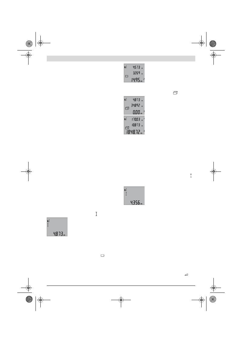
Lietuviškai |
157
Bosch Power Tools
2 609 140 773 | (4.12.12)
Nenukreipkite lazerio spindulio į kitus asmenis ar gyvū-
nus ir nežiūrėkite į lazerio spindulį patys, net ir būdami
atokiau nuo prietaiso.
Nusitaikykite lazerio spinduliu į nusitaikymo paviršių. Kad pra-
dėtumėte matavimą, trumpai paspauskite matavimo mygtuką
2
.
Esant nuolatinio matavimo funkcijai, matavimas pradedamas
iškart įjungiant funkciją.
Matavimo vertė paprastai parodoma maždaug po 0,5 s, vė-
liausia po 4 s. Matavimo trukmė priklauso nuo atstumo, švie-
sos sąlygų ir nusitaikymo paviršiaus atspindžio. Matavimui
pasibaigus, lazerio spindulys išjungiamas automatiškai.
Jei nusitaikius, maždaug per 20 s neatliekamas joks matavi-
mas, kad būtų taupomos baterijos, prietaisas išsijungia auto-
matiškai.
Bazinės plokštumos pasirinkimas (žr. pav. A)
Matavimui atlikti galite pasirinkti vieną iš trijų bazinių plokštu-
mų:
– matavimo prietaiso užpakalinis kraštas (pvz., dedant prie
sienos),
– matavimo prietaiso priekinis kraštas (pvz., matuojant nuo
salo krašto),
– sriegio
14
vidurys (pvz., matuojant su stovu).
Norėdami pasirinkti bazinę plokštumą, pakartotinai spauskite
mygtuką
6
, kol ekrane pasirodys norima bazinė plokštuma.
Kiekvieną kartą įjungus matavimo prietaisą, iš karto būna nu-
statyta matavimo prietaiso užpakalinio krašto bazinė plokštu-
ma.
Ekrano apšvietimas
Ekrano apšvietimas automatiškai suaktyvinamas priklauso-
mai nuo aplinkos šviesumo. Jei po ekrano apšvietimo įjungi-
mo nepaspaudžiamas joks mygtukas, kad būtų taupomos ba-
terijos, apšvietimas išjungiamas.
Matavimo funkcijos
Paprastas ilgio matavimas (žr. pav. B)
Norėdami matuoti ilgį, pakartotinai spauskite mygtuką
9
, kol
ekrane pasirodys ilgio matavimo simbolis .
Norėdami įjungti lazerį ir matuoti, vieną
kartą trumpai paspauskite matavimo
mygtuką
2
.
Matavimo vertė rodoma rezultato eilutėje
b
.
Vieną po kito atlikus kelis ilgio matavimus, matavimo verčių ei-
lutėse
a
parodomi paskutinių matavimų rezultatai.
Ploto matavimas (žr. pav. C)
Norėdami matuoti plotą, pakartotinai spauskite mygtuką
3
,
kol ekrane pasirodys ploto matavimo simbolis
.
Tada vieną po kito išmatuokite ilgį ir plotį, kaip aprašyta ilgio
matavimo skyrelyje. Tarp dviejų matavimų lazerio spindulys
lieka įjungtas.
Pasibaigus antrajam matavimui, plotas
apskaičiuojamas automatiškai ir parodo-
mas rezultato eilutėje
b
. Atskirų matavi-
mų vertės rodomos matavimo verčių eilu-
tėse
a
.
Tūrio matavimas (žr. pav. D)
Norėdami matuoti tūrį, pakartotinai spauskite mygtuką
3
, kol
ekrane pasirodys tūrio matavimo simbolis
.
Tada vieną po kito išmatuokite ilgį, plotį ir
aukštį, kaip aprašyta ilgio matavimo sky-
relyje. Tarp trijų matavimų lazerio spindu-
lys lieka įjungtas.
Pasibaigus trečiajam matavimui, tūris ap-
skaičiuojamas automatiškai ir parodomas
rezultato eilutėje
b
. Atskirų matavimų ver-
tės rodomos matavimo verčių eilutėse
a
.
Vertės, viršijančios 999999 m
3
, negali
būti parodytos; tokiu atveju ekrane rodo-
ma
„ERROR“
. Tūrį, kurį reikia išmatuoti, padalinkite į dalis ir
išmatavę susumuokite atskirų matavimų rezultatus.
Nuolatinis matavimas (žr. pav. E)
Atliekant nuolatinį matavimą, matavimo prietaisą galima ar-
tinti link nusitaikymo taško, artinant matavimo vertė atnauji-
nama maždaug kas 0,5 s. Pvz., jūs galite tolti nuo sienos iki
tam tikro norimo atstumo – ekrane visada bus rodoma esa-
mas nuotolis.
Kad prietaisas atliktų nuolatinį matavimą, spauskite mygtuką
9
tol, kol ekrane pasirodys nuolatinio matavimo simbolis .
Kad pradėtumėte nuolatinį matavimą, paspauskite matavimo
mygtuką
2
.
Esamoji matavimo vertė rodoma rezultato
eilutėje
b
.
Paspaudę matavimo mygtuką
2
, nutrau-
kiate nuolatinį matavimą. Paskutinė mata-
vimo vertė rodoma rezultato eilutėje
b
.
Dar kartą paspaudus matavimo mygtuką
2
vėl įsijungia nuolatinio matavimo režimas.
Po 5 min. nuolatinis matavimas automatiškai išsijungia. Pa-
skutinė matavimo vertė rodoma rezultato eilutėje
b
.
Netiesioginis aukščio matavimas / Paprastasis matavimas
pagal Pitagoro teoremą (žr. pav. F)
Netiesioginio aukščio matavimo funkcija skirta nustatyti ats-
tumams, kurių negalima išmatuoti tiesiogiai, nes spindulio ke-
lyje yra kliūtis, arba nėra galinčio atspindėti nusitaikymo pa-
viršiaus. Teisingi rezultatai gaunami tik tada, jei tiksliai išlaiko-
mi statūs kampai, reikalingi šiam matavimui atlikti (Pitagoro
teorema).
Stebėkite, kad matavimo bazinis taškas (pvz., matavimo prie-
taiso užpakalinis kraštas) per visus šios matavimo operacijos
atskirus matavimus būtų tiksliai toje pačioje vietoje.
Tarp atskirų matavimų lazerio spindulys lieka įjungtas.
Pakartotinai spauskite mygtuką
3
, kol ekrane pasirodys pa-
prastojo matavimo pagal Pitagoro teoremą simbolis
.
OBJ_BUCH-1444-004.book Page 157 Tuesday, December 4, 2012 1:47 PM
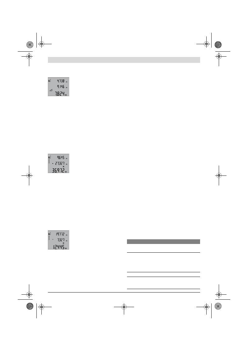
158
| Lietuviškai
2 609 140 773 | (4.12.12)
Bosch Power Tools
Taip pat, kaip ir atlikdami ilgio matavimą, išmatuokite atstumą
„1“
, o po to
„2“
. Atkreipkite dėmesį, kad tarp atstumo
„1“
ir
ieškomo atstumo
„X“
turi būti status kampas.
Baigus paskutinį matavimą ieškomo ats-
tumo
„X“
rezultatas parodomas rezultato
eilutėje
b
. Atskirų matavimų vertės rodo-
mos matavimo verčių eilutėse
a
.
Matavimo verčių trynimas
Trumpai paspaudę mygtuką
4
galite ištrinti visose matavimų
funkcijose nustatytas paskutines atskiras matavimų vertes.
Kelis kartus trumpai paspaudus mygtuką, atskiros matavimų
vertės ištrinamos atbuline tvarka.
Matavimo verčių sudėtis
Norėdami sudėti matavimų vertes, pirmiausia atlikite bet kokį
matavimą. Tada paspauskite pliuso mygtuką
8
. Kaip patvirti-
nimas apie atliktą veiksmą ekrane užsidega
„+“
.
Norėdami sudėti tūrius ar plotus, po pirmo atlikto matavimo
paspauskite pliuso mygtuką
8
. Kaip patvirtinimas apie atliktą
veiksmą ekrane, kairėje nuo tūrio/ploto simbolio užsidega
„+“
.
Tada atlikite antrą matavimą.
Norėdami pažiūrėti abiejų matavimų su-
mą, dar kartą paspauskite pliuso mygtuką
8
. Skaičiavimas rodomas matavimo ver-
čių eilutėse
a
, suma rodoma rezultato ei-
lutėje
b
.
Apskaičiavus sumą, jei prieš matavimą paspaudžiamas pliuso
mygtukas
8
, prie šio rezultato galima pridėti kitų matavimų
vertes.
Sudėties nuorodos:
– Negalima tarpusavyje sudėti ilgių, plotų ir tūrių verčių. Jei,
pvz, sudedama ilgio ir ploto vertė, paspaudus pliuso myg-
tuką
8
, ekrane trumpai parodomas pranešimas
„ERROR“
.
Po to matavimo prietaisas persijungia į paskiausia suakty-
vintą matavimo funkciją.
– Pridedamas atitinkamai vieno matavimo rezultatas (pvz.,
tūrio vertė), o atliekant nuolatinius matavimus – rezultato
eilutėje
b
parodyta matavimo vertė. Sudėti atskiras mata-
vimų vertes iš matavimo verčių eilučių
a
negalima.
Matavimo verčių atimtis
Norėdami atimti matavimo vertes, pa-
spauskite minuso mygtuką
5
, ekrane
parodomas
„–“
. Toliau reikia atlikti tokius
veiksmus, kaip aprašyta „Matavimo ver-
čių sudėtis“.
Darbo patarimai
Bendrosios nuorodos
Priėmimo lęšio
12
ir lazerio spindulio išėjimo angos
11
matuojant negalima uždengti.
Matavimo prietaiso matuojant judinti negalima (išskyrus nuo-
latinio matavimo funkciją). Todėl matavimo prietaisą padėki-
te prie kaip galima tvirtesnės atramos ar atraminio paviršiaus.
Įtaka matavimo diapazonui
Matavimo diapazonas priklauso nuo šviesos sąlygų ir
nusitaikymo paviršiaus atspindžio. Dirbdami lauke arba švie-
čiant saulei, kad geriau matytumėte lazerio spindulį, naudoki-
te akinius lazeriui matyti
19
(papildoma įranga) ir lazerio nusi-
taikymo lentelę
20
(papildoma įranga), arba nusitaikymo plo-
te padarykite šešėlį.
Įtaka matavimo rezultatams
Dėl fizikinių veiksnių, matuojant įvairių paviršių plotus, mata-
vimai gali būti klaidingi. Tai gali pasitaikyti, matuojant:
– permatomus paviršius (pvz., stiklą, vandenį),
– veidrodinius paviršius (pvz., poliruotą metalą, stiklą),
– akytus paviršius (pvz., izoliacines medžiagas),
– struktūrinius paviršius (pvz., struktūrinį tinką, natūralų
akmenį).
Jei reikia, matuodami šiuos paviršius naudokite lazerio nusi-
taikymo lentelę
20
(papildoma įranga).
Matavimo rezultatai gali būti klaidingi taip pat, jei kreivai nusi-
taikoma į nusitaikymo paviršių.
Matavimo vertei įtakos taip pat gali padaryti skirtingų tempe-
ratūrų oro sluoksniai arba netiesiogiai sugauti atspindžiai.
Tikslumo tikrinimas atstumo matavimu
Norėdami patikrinti atstumo matavimo tikslumą, atlikite šiuos
veiksmus:
– Pasirinkite nekintamą, maždaug nuo 1 iki 10 m ilgio mata-
vimo atstumą, kurio ilgis jums tiksliai žinomas (pvz., patal-
pos plotis, durų anga). Matavimo atstumas turi būti patal-
pos viduje, matavimo nusitaikymo paviršius lygus ir gerai
atspindintis.
– Išmatuokite tą atstumą 10 kartų iš eilės.
Atskirų matavimų nuokrypis nuo vidutinės vertės turi būti ne
didesnis kaip ±2 mm. Užregistruokite matavimo rezultatus
protokole, kad vėliau galėtumėte palyginti tikslumą.
Naudojimas su trikoju stovu (pap. įranga)
Stovas ypač reikalingas matuojant dideliu atstumu. Matavimo
prietaisą 1/4" sriegiu
14
prisukite prie stovo
18
greitojo keiti-
mo plokštelės arba prie standartinio trikojo stovo. Tvirtai už-
veržkite greitojo keitimo plokštės fiksuojamuoju varžtu.
Spausdami mygtuką
6
atitinkamai nustatykite bazinę matavi-
mo plokštumą, kai matuojama su stovu (bazinė plokštuma
„sriegis“).
Gedimai
–
priežastys ir pašalinimas
Priežastis
Pašalinimas
Įspėjamasis temperatūros simbolis (f) mirksi, matuoti
negalima
Matavimo prietaiso temperatūra
yra už darbinės temperatūros nuo
– 10 °C iki +50 °C ribų (veikiant
nuolatinio matavimo režimu
+40 °C).
Palaukite, kol matavimo
prietaisas pasieks darbi-
nę temperatūrą
Ekrane rodoma „ERROR“
Sudedamos/atimamos skirtingų
matavimo vienetų matavimo ver-
tės
Sudėkite/atimkite tik
vienodų matavimo vie-
netų matavimo vertes
OBJ_BUCH-1444-004.book Page 158 Tuesday, December 4, 2012 1:47 PM
中文
|
159
Bosch Power Tools
2 609 140 773 | (4.12.12)
Matavimo prietaisas kiekvieno matavimo
metu kontroliuoja, ar funkcija atliekama tin-
kamai. Nustačius defektą, ekrane mirksi tik
šalia pavaizduotas simbolis. Tokiu atveju ar-
ba nepašalinus gedimo aukščiau aprašyto-
mis priemonėmis, reikia kreiptis į prekybos
atstovą, kad matavimo prietaisas būtų pristatytas į Bosch kli-
entų aptarnavimo skyrių.
Priežiūra ir servisas
Priežiūra ir valymas
Sandėliuokite ir transportuokite matavimo prietaisą tik įdėję jį
į komplekte esantį apsauginį krepšį.
Matavimo prietaisas visuomet turi būti švarus.
Nepanardinkite matavimo prietaiso į vandenį ir kitokius skys-
čius.
Visus nešvarumus nuvalykite drėgnu minkštu skudurėliu. Ne-
galima naudoti jokių aštrių plovimo priemonių ir tirpiklių.
Ypatingai prižiūrėkite priėmimo lęšį
12
– taip pat rūpestin-
gai, kaip prižiūrimi akiniai arba fotoaparato lęšis.
Jei, nepaisant kruopščios gamybos ir patikrinimo, matavimo
prietaisas sugestų, jo remontas turi būti atliekamas įgaliotose
Bosch elektrinių įrankių remonto dirbtuvėse. Patys neatidary-
kite matavimo prietaiso.
Teiraudamiesi informacijos ir užsakydami atsargines dalis,
būtinai nurodykite dešimtženklį gaminio numerį, nurodytą
prietaiso firminėje lentelėje.
Remonto atveju matavimo prietaisą atsiųskite apsauginiame
krepšyje
17
.
Klientų aptarnavimo skyrius ir naudotojų konsul-
tavimo tarnyba
Klientų aptarnavimo skyriuje gausite atsakymus į klausimus,
susijusius su jūsų gaminio remontu, technine priežiūra bei at-
sarginėmis dalimis. Detalius brėžinius ir informaciją apie at-
sargines dalis rasite čia:
www.bosch-pt.com
Bosch naudotojų konsultavimo tarnybos specialistai mielai at-
sakys į klausimus apie mūsų gaminius ir papildomą įrangą.
Lietuva
Bosch įrankių servisas
Informacijos tarnyba: (037) 713350
ļrankių remontas: (037) 713352
Faksas: (037) 713354
El. paštas: service-pt@lv.bosch.com
Šalinimas
Matavimo prietaisai, papildoma įranga ir pakuotė turi būti su-
renkami ir perdirbami aplinkai nekenksmingu būdu.
Matavimo prietaisų, akumuliatorių bei baterijų nemeskite į
buitinių atliekų konteinerius!
Tik ES šalims:
Pagal Europos direktyvą 2002/96/EB, nau-
doti nebetinkami matavimo įrankiai ir, pagal
Europos direktyvą 2006/66/EB, pažeisti ir
išeikvoti akumuliatoriai bei baterijos turi
būti surenkami atskirai ir perdirbami aplin-
kai nekenksmingu būdu.
Galimi pakeitimai.
中文
安全规章
务必详细阅读说明书上所有的指示,如
此才能够安全而且有把握地操作仪器。
切勿涂抹或遮盖了仪器上的警戒牌。请
妥善保存本说明书。
注意
–
如果未按照本说明书中的指示操作仪器,
未使用本说明书推荐的调整装备,或者使用本仪器
进行其它的用途,都可能导致危险的辐射爆炸。
Per smailus kampas tarp lazerio
spindulio ir nusitaikymo linijos.
Padidinkite kampą tarp
lazerio spindulio ir
nusitaikymo linijos
Nusitaikymo paviršius atspindi per
stipriai (pvz., veidrodis) arba per
silpnai (pvz., juoda medžiaga), ar-
ba per stipri aplinkos šviesa.
Naudokite lazerio
nusitaikymo lentelę
20
(priedas)
Aprasojusi lazerio išėjimo anga
11
arba priėmimo lęšis
12
(pvz., grei-
tai kintant temperatūrai).
Minkštu skudurėliu
nusausinkite lazerio išė-
jimo angą
11
arba priė-
mimo lęšį
12
Apskaičiuota vertė yra didesnė už
999999 m/m
2
/m
3
.
Apskaičiavimą atlikite
etapais
Nelogiški matavimų rezultatai
Nevienodai atspindi nusitaikymo
paviršius (pvz., vanduo, stiklas).
Nusitaikymo paviršių
apdenkite
Uždengta lazerio išėjimo anga
11
arba priėmimo lęšis
12
.
Lazerio išėjimo angą
11
arba priėmimo lęšį
12
laikykite atidengtą
Nustatyta netinkama bazinė plokš-
tuma
Pasirinkite matavimui
tinkamą bazinę plokštu-
mą
Kliūtis lazerio spindulio trajektori-
joje
Lazerio taškas turi būti
ant nusitaikymo pavir-
šiaus.
Rodmuo lieka nepakitęs arba matavimo prietaisas netin-
kamai reaguoja į mygtuko paspaudimą
Programinės įrangos klaida.
Išimkite baterijas, vėl
įdėkite ir iš naujo įjunkite
matavimo prietaisą.
Priežastis
Pašalinimas
OBJ_BUCH-1444-004.book Page 159 Tuesday, December 4, 2012 1:47 PM

160
|
中文
2 609 140 773 | (4.12.12)
Bosch Power Tools
本仪器上贴着一个英文的警戒牌 (参考仪器详解图
上,以号码 15 标示的部位)。
使用仪器之前,先把附带的贴纸 (以贵国语言书写
的贴纸)贴在英文标示上。
不可以把激光光束指向人或动物,本身也不要直视
激光光束。 本测量仪投射的是符合 IEC 60825-1
标准的 2 级激光。 它会扰乱旁人的视觉能力。
激光辨识镜不可以充当防护眼镜。 戴上激光辨识镜
之后,可以帮助您辨识激光,它并不能保护您免受
激光辐射伤害。
不可以使用激光辨识镜充当太阳眼镜,也不可以戴
着激光辨识镜上街。 激光辨识镜不具备防护紫外线
的功能,并且会减弱您对颜色的识别能力。
本仪器只能交给合格的专业人员修理,而且只能使
用原厂的备件。 如此才能够确保仪器的安全性能。
不可以让儿童在无人监护的情况下使用激光测量
仪。 他们会因为不留心而扰乱旁人的视线。
不要在易爆环境,如有易燃液体、气体或粉尘的环
境下操作测量仪器。 测量仪器内可能产生火花并点
燃粉尘和气体。
产品和功率描述
请翻开标示了仪器图解的折叠页,阅读本说明书时必
须翻开折叠页参考。
按照规定使用机器
本仪器适用于测量距离,长度,高度和间距。也可以
使用本仪器计算面积和体积。本测量仪器适合在室内
和户外执行测量的工作。
技术数据
数字式激光测距仪
GLM 50
Professional
物品代码
3 601 K72 2..
测量范围
0,05
–50 米
A)
测量精度 (一般)
±1,5 毫米
B)
最小显示单位
1 毫米
工作温度范围
–10 °C...+50 °C
C)
储藏温度范围
–20 °C...+70 °C
最大相对空气湿度
90 %
激光等级
2
激光种类
635 纳诺米 , <1 毫瓦
激光束直径 (在摄氏 25 度)约
–
在 10 米远处
–
在 50 米远处
6 毫米
35 毫米
过了以下时间后自动关闭功能会发挥作用
–
激光
–
测量仪 (不测量时)
20 秒
5 分
电池
电池数目
2 x 1,5 伏特 LR03 (AAA)
2 x 1,2 伏特 HR03 (AAA)
电池使用寿命约
–
单一测量
–
持续测量
10000
D)
2,5 小时
D)
重量符合 EPTA-Procedure 01/2003
0,14 公斤
尺寸
53 x 114 x 30 毫米
保护种类
IP 54 (防尘埃和防水花)
OBJ_BUCH-1444-004.book Page 160 Tuesday, December 4, 2012 1:47 PM
中文
|
161
Bosch Power Tools
2 609 140 773 | (4.12.12)
插图上的机件
机件的编号和仪器详解图上的编号一致。
1
显示屏
2
测量按键
3
针对面积、体积和间接高度测量 (单毕达哥拉斯
定理)的按键
4
删除按键 / 起停按键 **
5
减少按键
6
选择固定参考点的按键
7
拎环接头
8
增加按键
9
长度测量和持续测量的按键
10
电池盒盖
11
激光放射口
12
接收透镜
13
序列号码
14
1/4" 螺孔
15
激光警戒牌
16
电池盒盖的固定扳扣
17
保护套
18
三脚架 *
19
激光辨识镜*
20
激光靶*
*图表或说明上提到的附件,並非包含在供货范围中。
** 按住按键以便呼叫延伸的功能。
显示图
a
测量值显示列
b
测量结果显示列
c
测量功能
d
激光被开启
e
测量的固定参考点
f
温度警告标志
g
电池电量警告标志
h
错误讯息指标 "ERROR"
安装
安装 / 更换电池
操作仪器时最好使用碱性锰电池或充电电池。
如果使用 1,2 伏特的充电电池,仪器的测量次数会比
使用 1,5 伏特的电池来得少。
打开电池盒盖
10
时,先按下固定扳扣
16
接著再取
出电池盒盖。装入电池或充电电池。 安装时请注意电
池极性的正确安装方向,电池室中有正确的安装参考
图。
安装电池或充电电池时请注意电池极性的正确安装方
向,电池室中有正确的安装参考图。
如果电池图形
首度出现在显示屏上, 那麽至少还
可以进行 100 次的测量工作。持续测量的功能是被关
闭的。
如果电池图形
已经开始闪烁,就得更换电池了。
此时已经无法继续使用仪器测量。
务必同时更换所有的电池或充电电池。 请使用同一制
造厂商,容量相同的电池或充电电池。
如果长期不使用测量仪,必须从测量仪器中取出电
池或充电电池。 经过长期搁置,电池会腐蚀或自行
放电。
正式操作
正式操作仪器
看管好已经开动的仪器。使用完毕后务必随手关闭
仪器。 激光可能扰乱旁人的视线。
不可以让湿气渗入仪器中,也不可以让阳光直接照
射在仪器上。
仪器不可以曝露在极端的气候下,也不可以把仪器
放在温差相当大的环境中。 仪器不可以长期放置在
汽车中。如果仪器先后曝露在温差相当大的环境
中, 必须先等待仪器温度恢复正常后再使用仪器。
A) 激光在目标表面的抛回 (散射,非反射)效果越好,它的射程就越远。如果激光的亮度超过周围环境的亮度 (例如在室内,或黄昏
时),也可以加强射程。在条件不佳的工作环境下 (例如在烈日下进行测量时),最好使用激光瞄准靶。
B) 针对从测量仪器的后缘开始测量时。如果工作环境不理想,例如日照强烈或者目标表面的反射度不良,在 50 米远处的最大测量误差为
±
10 毫米。在有利的工作环境下, 测量误差约为
±
0,05 毫米 / 米。
C) 执行持续测量时,最高的工作温度为摄氏 40 度。
D) 如果使用 1,2 伏特的充电电池,仪器的测量次数会比使用 1,5 伏特的电池来得少。 以上标示的电池使用寿命是针对不使用显示屏照明
时的测量。
仪器铭牌上的序列号码 ( 仪器详解上标示著
13
的位置 ) 便是仪器的识别码。
长度测量
持续测量
面积测量
体积测量
单毕达哥拉斯测量
OBJ_BUCH-1444-004.book Page 161 Tuesday, December 4, 2012 1:47 PM
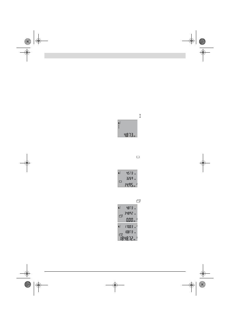
162
|
中文
2 609 140 773 | (4.12.12)
Bosch Power Tools
如果仪器曝露在极端的气候下或温差相当大的环境
中,会影响仪器的测量准确度。
不可以剧烈地撞、摔测量仪。 经过强烈的外力冲撞
后,必须检查测量仪的测量精度,然后才能够继续
使用测量仪 (参考 " 距离测量的精度检验 ", 页
数 164)。
开动 / 关闭
开动 测量仪器,可以使用以下各种方式:
–
按下起停按健
4
:可以开动测量仪器并且仪器是设
定在长度测量的操作模式上。并未启动激光。
–
按下测量按键
2
: 可以开动测量仪器和启动激光。
此时仪器是设 定在长度测量的操作模式上。
不可以把激光指向人或动物。您本人也不可以直视
激光。就算您与激光之间尚有一段距离,也不可忽
视激光的伤害力。
关闭 测量仪, 按住起停开关按键
4
,得让手指头在按
键上停留一段时间。
如果在 5 分钟内未按下仪器上的任何按键,测量仪会
自动关闭以保护电池。
测量过程
按下测量按键
2
并开动仪器之后,测量仪器是被设定
在长度测量的功能上。您可以使用各别的功能按键,
来选择其它的测量功能 (参考 " 测量功能 ", 页数
162)。
开机后的测量基本面,是设定在测量仪的后缘上。使
用固定参考点按键
6
可以改变基本面 (参考 " 选择
基本面 ",页数 162)。
把测量仪 (已经选择好)的固定参考点靠在希望的测
量起始点上 (例如墙壁)。
短暂地按住测量按键
2
便可以启动激光光束。
不可以把激光指向人或动物。您本人也不可以直视
激光。就算您与激光之间尚有一段距离,也不可忽
视激光的伤害力。
以激光束瞄准目标。重新按一下测量按键
2
以启动测
量功能。
选择了持续测量的功能之后,只要一开机仪器便开始
测量。
通常在 0,5 秒之内会显示测量值,最迟在 4 秒钟之后
会出现测量值。测量时间的长短是由测量的距离,光
线的强弱以及目标表面的反射状况等因素来决定。完
成测量之后仪器会自动关闭激光。
如果在做好瞄准工作之后未马上进行测量,约 20 秒
后激光会自动关闭以便保护电池。
选择基本面 (参考插图 A)
测量时可以选择三个不同的固定参考点:
–
测量仪器的后缘 (例如靠在墙壁上),
–
测量仪的前缘 (例如从桌边开始测量时),
–
螺纹孔
14
的中央 (例如使用三脚架测量时)。
选择固定参考点时必须重复按下按键
6
, 至显示屏上
出现需要的固定参考点为止。 开机时,固定参考点是
设定在仪器的后缘上。
显示屏照明
显示屏的照明设备会根据周围环境的亮度而自动开
启。 在显示屏的照明设备被开启之后,如果操作者未
按下任何按键,为了保护电池照明光线会变暗。
测量功能
单一长度测量 (参考插图 B)
进行长度测量时必须连续按下按键
9
至显示屏上出现
长度测量的标志
为止。
启动激光和进行测量时各按一次测
量按键
2
。
测量值会显示在测量结果显示列
b
。
进行连续数次的长度测量时, 最后
一次的测量结果会出现在测量值显
示列
a
上。
测量面积 (参考插图 C)
进行面积测量时必须连续按按键
3
至显示屏上出现面
积测量的标志
为止。
使用测量长度的方式,先后测量该面积的长和宽。在
进行长,宽测量时,激光都是开着的。
当您完成第二个测量步骤后, 仪器
会自动进行运算并将运算所得的面
积显示在测量结果显示列
b
上。 个
别的测量值会出现在测量值显示列
a
。
体积测量 (参考插图 D)
进行体积测量时必须连续按按键
3
至显示屏上出现体
积测量的符号
为止。
使用测量长度的方式,先后测量该
面积的长 , 宽和高。在进行长,宽,
高测量时,激光都是开着的。
当您完成第三个测量步骤后, 仪器
会自动进行运算并将运算所得的体
积显示在测量结果显示列
b
上。个
别的测量值会出现在测量值显示列
a
。
仪器无法显示超过 999999 m
3
的值,此时显示屏会出
现 "ERROR"。您可以把待测量的面积分割成数个单一
测量。分别计算各单一测量的体积,然后再累加各个
体积。
OBJ_BUCH-1444-004.book Page 162 Tuesday, December 4, 2012 1:47 PM
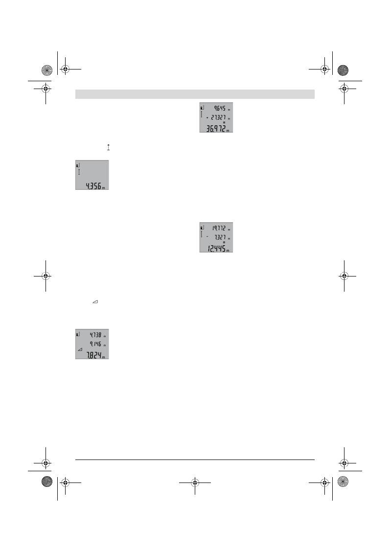
中文
|
163
Bosch Power Tools
2 609 140 773 | (4.12.12)
持续测量 (参考插图 E)
进行持续测量时可以将测量仪器移向测量目标。 此时
每 0,5 秒仪器便会更新一次测量值。 例如您可以根据
需要测量到墙壁的距离,仪器上随时会显示最新的距
离。
执行持续测量时要连续按下按键
9
至显示屏上出现持
续测量的标志
为止。按下测量按键
2
便可以开始
进行持续测量。
目前的测量值会显示在测量结果显
示列
b
。
轻按测量按键
2
可以结束持续测量
功能。最後一个测量值会显示在测
量结果显示列
b
上。重新按下测量
按键
2
仪器会重新执行持续测量功
能。
5 分钟之后持续测量功能会自动关闭。 最后一个测量
值会显示在测量结果显示列
b
上。
间接高度测量 / 单毕达哥拉斯测量 (参考插图 F)
无法进行直接测量时 (例如有障碍物会阻挡激光, 或
者没有目标可以充当反射体时),则必须以间接的方
式测量高度。 在激光和待测量的线段的夹角成直角
时, 才能够测量出正确的结果 (毕达哥拉斯定理)。
注意,在一个测量过程中的所有单一测量,都必须具
备完全相同的的固定参考点 (例如测量仪器的后
缘)。
在各个单一测量之间的空档激光仍然是开启着的。
连续地按下按键
3
至显示屏上出现单毕达哥拉斯测量
的标志
为止。
如同长度测量一般,先后测出距离 "1" 和距离 "2"
的值。 务必注意,线段 "1" 和待测量的线段 "X" 之
间必须成直角。
当您完成最后一个测量步骤后, 仪
器会把 "X" 线段的值显示在测量结
果显示列
b
上。 个别的测量值会出
现在测量值显示列
a
。
取消测量值
不论您正在使用哪一种测量功能,只要轻按按键
4
便
可以取消最后一次的单一测量值。连续地轻按这个按
键,可以由后往前逐一删除各个单一测量值。
相加测量值
欲相加测量值要先进行测量。 接著按下增加按键
8
。
显示屏上会出现 "+".
来确认。如果要相加体积或面积,在结束第一道测量
过程之后要按下增加按键
8
。 此时显示屏上的体积 /
面积标志的左边会出现 "+" 确认。
接着再进行第二道测量。
再度按下增加按键
8
,便可以询问
两个测量值的总和。 计算过程会出
现在测量值显示列
a
, 总和则显示
在测量结果显示列
b
。
运算完毕后,如果在每次测量之前按下增加按键
8
,
便可以将下一笔的测量值 相加到运算总和中。
有关相加功能的指示:
–
长度值,面积值和体积值不可以混合相加。 举例来
说,如果相加长度值和面积值,在按下增加按键
8
后显示屏上会短暂地出现 "ERROR"。然后测量仪器
便会转换回上一个测量功能。
–
一般而言相加的都是测量后的结果 (例如体积
值)。如果是进行持续测量,则相加显示在测量结
果显示列
b
上的值。 出现在测量值显示列
a
上的
各别测量值是无法相加的。
删减测量值
删减测量值时必须按下减少按键
5
。
显示屏上会出现 "
–" 来确认。 接
下来的步骤和 " 相加测量值 " 相
同。
有关操作方式的指点
一般性的指示
测量时不可以遮盖住接收透镜
12
和激光发射口
11
。
进行测量时不可以移动测量仪器 (使用持续测量功能
时例外)。 因此要尽可能把测量仪器放在坚固的平面
或底垫上。
影响测量范围的因素
测量范围会受光线的明暗,以及目标表面的反射特性
等因素影响。当您在户外或者在日照强烈的环境中进
行测量时,可以佩戴激光辨识镜
19
(附件)和使用
激光瞄准靶
20
(附件)以方便辨识激光,或者也可
以遮暗目标表面。
影响测量结果的因素
基于物理原理,不能排除在某些特定的物表进行测量
时会产生误差。例如:
–
透明的表面 (玻璃,水等),
–
会反射的表面 (经过抛光的金属,玻璃),
–
多孔的表面 (例如隔离材料),
–
有纹路的表面 (例如粗糙的灰泥墙,天然石)。
必要时得在这些物表放置激光瞄准靶
20
(附件)。
如果未正确地瞄准好目标点,也可能产生误测。
此外有温差的空气层和间接的反射都可能影响测量
值。
OBJ_BUCH-1444-004.book Page 163 Tuesday, December 4, 2012 1:47 PM
164
|
中文
2 609 140 773 | (4.12.12)
Bosch Power Tools
距离测量的精度检验
您可以遵循以下的指示来检查距离测量的精度:
–
选择一段不会改变而且您非常了解的测量距离,约
1 至 10 米长 (例如房间的宽度,门孔的高度)。
测量的距离位置必须位在室内。
–
先后在该距离进行 10 次测量。
单一测量值和平均值的最大差距不可以超过
±2 毫
米。 要做好测量记录,以便日后充当检查仪器精确度
的根据。
使用三脚架工作 (附件)
当测量目标位在远处时,则必须使用三脚架。把测量
仪上的 1/4" 螺孔
14
安插在三脚架
18
的快速更换
板上。或者您也可以使用一般市面上的照相机三脚
架。
使用三脚架帮助测量之前,先按下按键
6
选择合适的
固定参考点 (固定参考点,螺孔)。
故障
–
原因和处理措施
每次进行测量时,测量仪器会自动监
控运作功能。 如果发现故障,左侧的
图形会在显示屏上闪烁。当显示屏上
出现这个图形,或者无法以上述的处
理措施排除故障,必须把仪器交给经
销商或博世顾客服务中心修理。
维修和服务
维修和清洁
使用附带的保护套储存和携带仪器。
测量仪器必须随时保持清洁。
不可以把仪器放入水或其它的液体中。
使用潮湿,柔软的布擦除仪器上的污垢。不可以使用
洗涤剂或溶剂清洁仪器。
小心地维护、清洁接收透镜
12
,就好比您清洁眼镜
和照相机的透镜一般。
虽然本公司生产的仪器在出厂之前都经过严格的品质
检验, 如果仍然发生故障,请将仪器 交给博世电动
工具公司授权的客户服务处修理。 不可以擅自打开测
量仪器。
查询和订购备件时,务必提供仪器铭牌上标示的
10 位数物品代码。
将仪器送修之前,必须先把仪器放入防护套
17
中。
顾客服务处和顾客咨询中心
本公司顾客服务处负责回答有关本公司产品的修理,
维护和备件的问题。以下的网页中有爆炸图和备件的
资料 :
www.bosch-pt.com
博世顾客咨询团队非常乐意为您解答
有关本公司产品及附件的问题。
有关保证,维修或更换零件事宜,请向合格的经销商
查询。
中国大陆
博世电动工具 (中国)有限公司
中国 浙江省 杭州市
滨江区滨康路 567 号
邮政编码:310052
免费服务热线: 4008268484
传真:(0571) 87774502
电邮:contact.ptcn@cn.bosch.com
www.bosch-pt.com.cn
原因
处理措施
温度警告标志 (
f
) 开始闪烁,无法继续测量
测量工具的温度位在工作温度
范围,摄氏零下 10 度到摄氏
50 度,之外 (执行持续测量
时的温度上限为摄氏 40 度)。
停下工作静待测量仪
的温度回升到工作温
度范围内。
显示屏上出现 "ERROR"
合并 / 删减不同测量单位的测
量值。
只能合并 / 删减相同
测量单位的测量值。
激光和目标之间的角度太狭小。 加大激光和目标之间
的角度。
目标的反射太强 (例如镜
子),太弱 (例如黑色物料)
或者周围环境太亮。
使用激光瞄准靶
20
(附件)。
激光发射口
11
或接收透镜
12
上蒙着一层雾气 (由于快速的
温差变化)。
使用柔软的布擦干激
光发射口
11
和接收
透镜
12
。
运算值超过 999999 米 / 平方
米 / 立方。
把总运算分割成数个
过度运算过程
测量结果不可靠
目标无法正确反射 (例如水,
玻璃)。
盖住目标。
激光发射口
11
和接收透镜
12
被遮盖住了。
拿开激光发射口
11
和接收透镜
12
前的
遮盖物。
设定了错误的固定参考点。
选择适合测量功能的
固定参考点。
在激光的射程中存在障碍物。
激光点必须完全投射
在目标表面。
指示标志无变化或者在按下按键后测量仪器有出乎意
料的反应
软件出了错误。
拿出电池,并在重新
装回电池后开动测量
仪器。
原因
处理措施
OBJ_BUCH-1444-004.book Page 164 Tuesday, December 4, 2012 1:47 PM
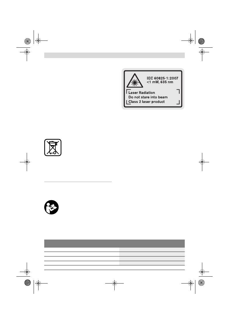
中文
|
165
Bosch Power Tools
2 609 140 773 | (4.12.12)
羅伯特
博世有限公司
香港北角英皇道 625 號 21 樓
客戶服務熱線:+852 2101 0235
傳真:+852 2590 9762
電郵:info@hk.bosch.com
網站:www.bosch-pt.com.hk
制造商地址:
罗伯特博世有限公司
营业范围电动工具
邮箱号码 100156
70745 Leinfelden-Echterdingen (莱菲登 - 艾希德登)
Deutschland (德国)
处理废弃物
必须以符合环保要求的方式回收再利用损坏的仪器,
附件和包装材料。
不可以把损坏的探测仪和蓄电池 / 电池丢弃在一般的
家庭垃圾中!
只针对欧盟国家:
根据欧洲的法规 2002/96/EG,必须
把不再使用的测量仪器,根据欧洲的
法规 2006 /66 / EG,必须把损耗的
蓄电池 / 电池,分开收集 并且以符合
环保要求的方式回收再利用。
保留修改权。
中文
安全規章
務必詳細閱讀說明書上所有的指示,如
此才能夠安全而且有把握地操作儀器。
切勿涂抹或遮蓋了儀器上的警戒牌。請
妥善保存本說明書。
注意
– 如果未按照本說明書中的指示操作儀器,
未使用本說明書推薦的調整裝備,或者使用本儀器
進行其它的用途,都可能導致危險的輻射爆炸。
本儀器上貼著一塊英文的警戒牌 (參考儀器詳解圖
上,以號碼
15
標示的部位)。
使用儀器之前,先把附帶的貼紙 (以貴國語言書寫
的貼紙)貼在英文標示上。
不可以把激光光束指向人或動物,本身也不要直視
激光光束。 本測量儀投射的是符合 IEC 60825
-
1
標準的 2 級激光。它會擾亂旁人的視覺能力。
激光辨識鏡不可以充電防護眼鏡。 戴上激光辨識鏡
之后,可以幫助您辨識激光,它並不能保護您免受
激光輻射傷害。
不可以使用激光辨識鏡充當太陽眼鏡,也不可以戴
著激光辨識鏡上街。 激光辨識鏡不具備防止紫外線
功能,而且會減弱您對顏色的辨識能力。
本測量儀只能交給合格的專業人員修理,而且只能
使用原廠的備件。 如此才能夠確保儀器的安全性
能。
不可以讓兒童在無人監護的情況下使用激光測量
儀。 他們可能會因為輕心而擾亂旁人的視線。
不要在易爆環境,如有易燃液體、氣體或粉塵的環
境下操作測量儀器。 測量儀器內可能產生火花並點
燃粉塵和氣體。
產品和功率描述
請翻開標示了儀器圖解的折疊頁,閱讀本說明書時必
須翻開折疊頁參考。
按照規定使用機器
本儀器適用于測量距離,長度,高度和間距。也可以
使用本儀器計算面積和體積。本測量儀器適合在室內
和戶外執行測量的工作。
技術性數據
數字式激光測距儀
GLM 50
Professional
物品代碼
3 601 K72 2..
測量範圍
0,05
–50 米
A)
測量精度 (一般)
±1,5 毫米
B)
最小的顯示單位
1 毫米
OBJ_BUCH-1444-004.book Page 165 Tuesday, December 4, 2012 1:47 PM
166
|
中文
2 609 140 773 | (4.12.12)
Bosch Power Tools
插圖上的機件
機件的編號和儀器詳解圖上的編號一致。
1
顯示屏
2
測量按鍵
3
針對面積、體積和間接高度測量 (單畢達哥拉斯
定理)的按鍵
4
刪除按鍵 / 起停按鍵 **
5
減少按鍵
6
選擇固定參考點的按鍵
7
拎環接頭
8
增加按鍵
9
長度和持續測量按鍵
10
電池盒蓋
11
激光放射口
12
接收透鏡
13
序列號碼
14
1/4" 螺孔
15
激光警戒牌
16
電池盒蓋的固定扳扣
17
保護套
18
三腳架 *
19
激光辨識鏡*
20
激光靶*
*插圖中或說明書中提到的附件,并不包含在正常的供貨範圍
中。
** 按住按鍵以便呼叫延伸的功能
顯示圖
a
測量值顯示列
b
測量結果顯示列
c
測量功能
工作溫度範圍
–10 °C...+50 °C
C)
儲藏溫度範圍
–20 °C...+70 °C
最大相對空氣濕度
90 %
激光等級
2
激光種類
635 納米 , <1 豪瓦
激光束直徑 (在攝氏 25 度)約
–
在 10 米遠處
–
在 50 米遠處
6 毫米
35 毫米
過了以下時間後自動關閉功能會發揮作用
–
激光
–
測量儀 (不測量時)
20 秒
5 分
電池
電池數目
2 x 1,5 伏特 LR03 (AAA)
2 x 1,2 伏特 HR03 (AAA)
電池使用壽命約
–
單一測量
–
持續測量
10000
D)
2,5 小時
D)
重量符合 EPTA-Procedure 01/2003
0,14 公斤
尺寸
53 x 114 x 30 毫米
保護種類
IP 54 (防灰塵和防水花)
數字式激光測距儀
GLM 50
Professional
A) 激光在目標表面的拋回 (散射,非反射)效果越好,它的射程就越遠。 如果激光的亮度超過周圍環境的亮度 (例如在室內或黃昏
時), 也可以加強射程。在條件不佳的工作環境下 (例如在烈日下進行測量時), 最好使用激光瞄準靶。
B) 針對從測量儀器的後緣開始測量時。 如果工作環境不理想,例如日照強烈或者目標表面的反射度不良, 在 50 米遠處的最大測量誤差為
±
10 毫米。在有利的工作環境下, 測量誤差約為
±
0,05 毫米 / 米。
C) 進行持續測量時,最高的工作溫度為攝氏 40 度。
D) 如果使用 1,2 伏特的充電電池,儀器的測量次數會比使用 1,5 伏特的電池來得少。 以上標示的電池使用壽命是針對不使用顯示屏照明
時的測量。
儀器銘牌上的序列號碼 (儀器詳解圖上標示
13
的位置)便是儀器的識別碼。
長度測量
持續測量
面積測量
體積測量
單畢達哥拉斯測量
OBJ_BUCH-1444-004.book Page 166 Tuesday, December 4, 2012 1:47 PM
中文
|
167
Bosch Power Tools
2 609 140 773 | (4.12.12)
d
激光被開啟
e
測量的固定參考點
f
溫度警告標志
g
電池電量警告標志
h
錯誤訊息指標 "ERROR"
安裝
安裝 / 更換電池
操作儀器時最好使用堿性錳電池或充電電池。
如果使用 1,2 伏特的充電電池,儀器的測量次數會比
使用 1,5 伏特的電池來得少。
打開電池盒蓋
10
時,先按下固定扳扣
16
接著再取
出電池盒蓋。裝入電池或充電電池。安裝時請注意電
池極性的正確安裝方向,電池室中有正確的安裝參考
圖。
安裝電池或充電電池時請注意電池極性的正確安裝方
向,電池室中有正確的安裝參考圖。
如果電池圖形
首度出現在顯示屏上, 那麼至少還
可以進行 100 次的測量工作。持續測量的功能是被關
閉的。
如果電池圖形
已經開始閃爍,就得更換電池了。
此時已經無法繼續使用儀器測量。
務必同時更換所有的電池或充電電池。 請使用同一制
造廠商,容量相同的電池或充電電池。
如果長期不使用測量儀,必須從測量儀器中取出電
池或充電電池。 經過長期擱置,電池會腐蝕或自行
放電。
正式操作
操作
看管好已經開動的儀器。使用完畢後務必隨手關閉
儀器。 激光可能擾亂旁人的視線。
不可以讓濕氣滲入儀器中,也不可以讓陽光直接照
射在儀器上。
儀器不可以曝露在極端的氣候下,也不可以把儀器
放在溫差相當大的環境中。 例如儀器不可以長期放
置在汽車中。如果儀器先后曝露在溫差相當大的環
境中,必須先等待儀器的溫度恢復正常後再使用儀
器。如果儀器曝露在極端的氣候下或溫差相當大的
環境中,會影響儀器的測量準確度。
不可以劇烈地撞、摔測量儀 經過強烈的外力沖撞
後,必須檢查測量儀的測量精度, 然后才能夠繼續
使用測量儀 ( 參考 " 距離測量的精度檢驗 ", 頁
數 169)。
開動 / 關閉
開動 開動測量儀器,可以使用以下各種方式 :
–
按下起停按健
4
: 可以開動測量儀器並且儀器是設
定在長度測量的操作模式上。並未啟動激光。
–
按下測量按鍵
2
: 可以開動測量儀器和啟動激光。
此時儀器是設 定在長度測量的操作模式上。
不可以把激光指向人或動物,您本人也不可以直視
激光。就算您與激光之間尚有一段距離,也不可以
忽視激光的傷害力。
關閉 測量儀,按住起停開關按鍵
4
,得讓手指頭在按
鍵上停留一段時間。
如果在 5 分鐘內未按下儀器上的任何按鍵,測量儀會
自動關閉以保護電池。
測量過程
按下測量按鍵
2
並開動儀器之後,測量儀器是被設定
在長度測量的功能上。您可以使用各別的功能按鍵,
來選擇其它的測量功能 (參考 " 測量功能 ", 頁
數 168)。
開機後的測量基本面,是設定在測量儀的後緣上。 使
用固定參考點按鍵
6
可以改變基本面 (參考 " 選擇
基本面 ",頁數 167)。
把測量儀 (已經選擇好)的固定參考點靠在希望的測
量起始點上 (例如牆壁)。
短暫地按住測量按鍵
2
便可以啟動激光光束。
不可以把激光指向人或動物,您本人也不可以直視
激光。就算您與激光之間尚有一段距離,也不可以
忽視激光的傷害力。
以激光束瞄準目標。重新按一下測量按鍵
2
以啟動測
量功能。
選擇了持續測量的功能之后,只要一開機儀器便開始
測量。
通常在 0,5 秒之內會顯示測量值,最遲在 4 秒鐘之
後會出現測量值。測量時間的長短是由測量的距離,
光線的強弱以及目標表面的反射狀況等因素來決定。
完成測量之後儀器會自動關閉激光。
如果在做好瞄準工作之后未馬上進行測量,約 20 秒
之后激光會自動關閉以保護電池。
選擇基本面 (參考插圖 A)
測量時可以選擇三個不同的固定參考點 :
–
測量儀器的後緣 (例如靠在牆壁上),
–
測量儀的前緣 (例如從桌邊開始測量時),
–
螺紋孔
14
的中央 (例如使用三腳架測量時)。
選擇固定參考點時必須重復按下按鍵
6
, 至顯示屏上
出現需要的固定參考點為止。 開機時,固定參考點是
設定在儀器的後緣上。
OBJ_BUCH-1444-004.book Page 167 Tuesday, December 4, 2012 1:47 PM
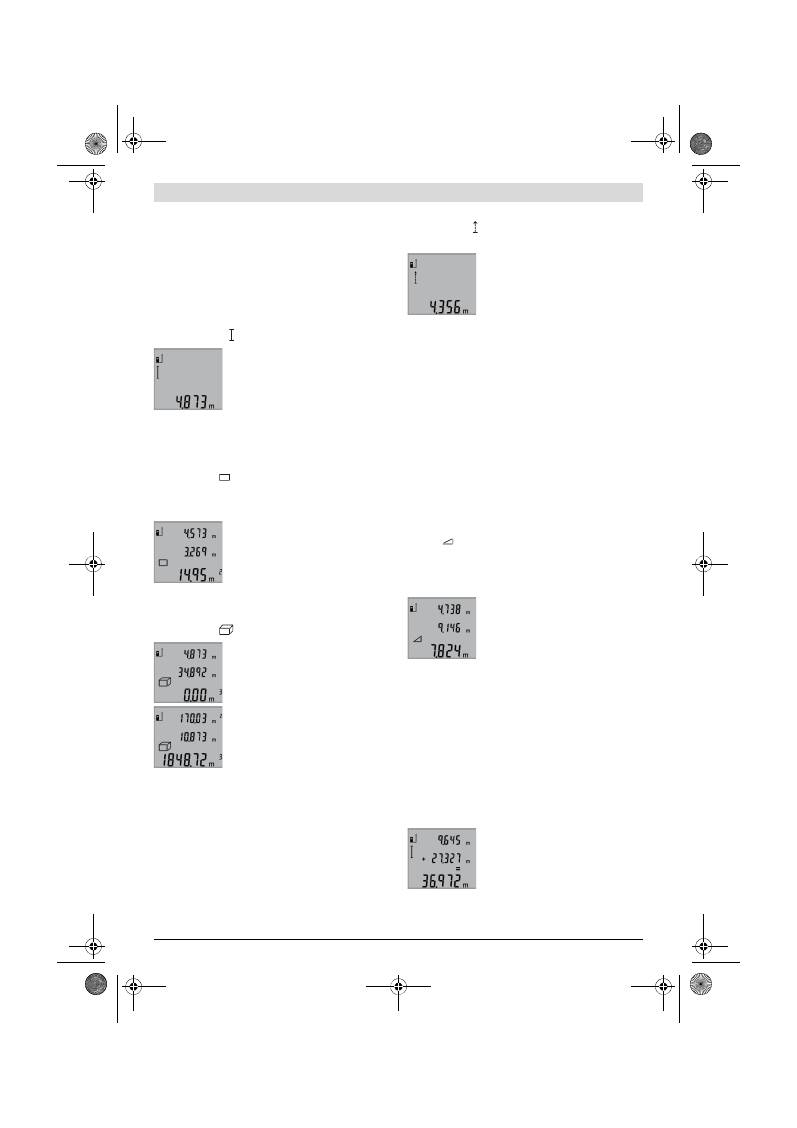
168
|
中文
2 609 140 773 | (4.12.12)
Bosch Power Tools
顯示屏照明
顯示屏的照明設備會根據周圍環境的亮度而自動開
啟。 在顯示屏的照明設備被開啟之後,如果操作者未
按下任何按鍵,為了保護電池照明光線會變暗。
測量功能
單一長度測量 (參考插圖 B)
進行長度測量時必須連續按下按鍵
9
至顯示屏上出現
長度測量的標志
為止。
啟動激光和進行測量時各按一次測
量按鍵
2
。
測量值會顯示在測量結果顯示列
b
。
進行連續數次的長度測量時, 最後
一次的測量結果會出現在測量值顯
示列
a
上。
測量面積 (參考插圖 C)
進行面積測量時必須連續按按鍵
3
至顯示屏上出現面
積測量的標志
為止。
根據長度測量的方式,先后測量長和寬。在進行長、
寬測量時激光一直是開著的。
當您完成第二個測量步驟後, 儀器
會自動進行運算並將運算所得的面
積顯示在測量結果顯示列
b
上。 個
別的測量值會出現在測量值顯示列
a
。
體積測量 (參考插圖 D)
進行體積測量時必須連續按按鍵
3
至顯示屏上出現體
積測量的符號
為止。
使用測量長度的方式,先后測量該
體積的長,寬和高。在進行長,寬,
高的測量時,激光一直是開著的。
當您完成第三個測量步驟後, 儀器
會自動進行運算並將運算所得的體
積顯示在測量結果顯示列
b
上。個
別的測量值會出現在測量值顯示列
a
。
儀器無法顯示超過 999999 m
3
的值,此時顯示屏會出
現 "ERROR"。您可以把待測量的面積分割成數個單一
測量。分別計算各單一測量的體積,然後再累加各個
體積。
持續測量 (參考插圖 E)
進行持續測量時可以將測量儀器移向測量目標。 此時
每 0,5 秒儀器便會更新一次測量值。 例如您可以根據
需要測量到牆壁的距離 : 儀器上隨時會顯示最新的距
離。
執行持續測量時要連續按下按鍵
9
至顯示屏上出現持
續測量的標志
為止。按下測量按鍵
2
便可以開始
進行持續測量。
目前的測量值會顯示在測量結果顯
示列
b
。
輕按測量按鍵
2
可以結束持續測量
功能。 最後一個測量值會顯示在測
量結果顯示列
b
上。重新按下測量
按鍵
2
儀器會重新執行持續測量功
能。
5 分鐘之后持續測量功能會自動關閉。 最後一個測量
值會顯示在測量結果顯示列
b
上。
間接高度測量 / 單畢達哥拉斯測量 (參考插圖 F)
無法進行直接測量時 (例如有障礙物會阻擋激光, 或
者沒有目標可以充當反射體時),則必須以間接的方
式測量高度。 在激光和待測量的線段的夾角成直角
時, 才能夠測量出正確的結果 (畢達哥拉斯定理)。
注意,在一個測量過程中的所有單一測量,都必須具
備完全相同的的固定參考點 (例如測量儀器的後
緣)。
在各個單一測量之間的空檔激光仍然是開啟著的。
連續地按下按鍵
3
至顯示屏上出現單畢達哥拉斯測量
的標志
為止。
如同長度測量一般,先後測出距離 "1" 和距離 "2"
的值。 務必注意,線段 "1" 和待測量的線段 "X" 之
間必須成直角。
當您完成最後一個測量步驟後, 儀
器會把 "X" 線段的值顯示在測量結
果顯示列
b
上。 個別的測量值會出
現在測量值顯示列
a
。
取消測量值
不論您正在使用哪一種測量功能,只要輕按按鍵
4
便
可以取消最后一次的單一測量值。連續地輕按這個按
鍵,可以由後往前逐一刪除各個單一測量值。
相加測量值
欲相加測量值要先進行測量。 接著按下增加按鍵
8
。
顯示屏上會出現 "+"。
來確認。如果要相加體積或面積,在結束第一道測量
過程之後要按下增加按鍵
8
。 此時顯示屏上的體積 /
面積標志的左邊會出現 "+" 確認。
接著再進行第二道測量。
再度按下增加按鍵
8
,便可以詢問
兩個測量值的總和。 計算過程會出
現在測量值顯示列
a
, 總和則顯示
在測量結果顯示列
b
。
運算完畢後,如果在每次測量之前按下增加按鍵
8
,
便可以將下一筆的測量值 相加到運算總和中。
OBJ_BUCH-1444-004.book Page 168 Tuesday, December 4, 2012 1:47 PM
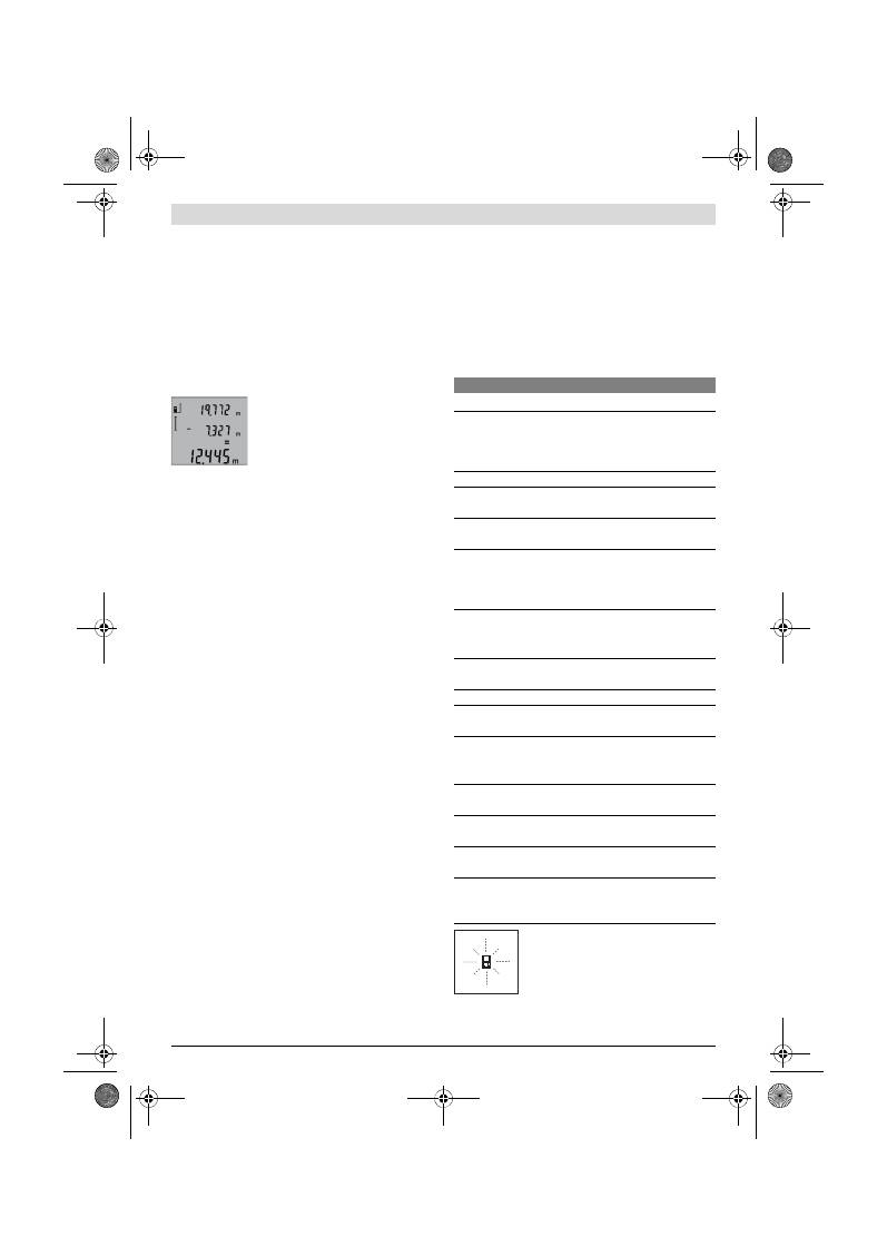
中文
|
169
Bosch Power Tools
2 609 140 773 | (4.12.12)
有關相加功能的指示 :
–
長度值,面積值和體積值不可以混合相加。 舉例來
說,如果相加長度值和面積值,在按下增加按鍵
8
後顯示屏上會短暫地出現 "ERROR" 。然後測量儀
器便會轉換回上一個測量功能。
–
一般而言相加的都是測量後的結果 (例如體積
值)。 如果是進行持續測量,則相加顯示在測量結
果顯示列
b
上的值。 出現在測量值顯示列
a
上的
各別測量值是無法相加的。
刪減測量值
刪減測量值時必須按下減少按鍵
5
。
顯示屏上會出現 "
–" 來確認。 接
下來的步驟和 " 相加測量值 " 相
同。
有關操作方式的指點
一般性的指示
測量時不可以遮蓋住接收透鏡
12
和激光發射口
11
。
進行測量時不可以移動測量儀器 (使用持續測量功能
時例外)。 因此要盡可能把測量儀器放在堅固的平面
或底墊上。
影響測量範圍的因素
測量範圍會受光線的明暗,以及目標表面的反射特性
等因素影響。當您在戶外或者在日照強烈的環境中進
行測量時,可以佩戴激光辨識鏡
19
(附件)和使用
激光瞄準靶
20
(附件)以方便辨識激光,或者也可
以遮暗目標表面。
影響測量結果的因素
基于物理原理,不能排除在某些特定的物表進行測量
時會產生誤差。 例如 :
–
透明的表面 (玻璃,水等),
–
會反射的表面 (經過拋光的金屬,玻璃),
–
多孔的表面 (例如隔離材料),
–
有紋路的表面 (例如粗糙的灰泥牆,天然石)。
必要時得在這些物表放置激光瞄準靶
20
(附件)。
如果未正確地瞄準好目標點,也可能產生誤測。
此外有溫差的空氣層和間接的反射都可能影響測量
值。
距離測量的精度檢驗
您可以遵循以下的指示來檢查距離測量的精度:
–
選擇一段不會改變而且您非常了解的測量距離,約
1 至 10 米長 (例如房間的寬度,門孔的高度)。
測量的距離位置必須位在室內。測量目標的表面必
須是光滑的而且要具備良好的反射性。
–
先後在該距離進行 10 次測量。
單一測量值和平均值的最大差距不可以超過
±2 毫
米。 要做好測量記錄 , 以便日後充當檢查儀器精確度
的根據。
使用三腳架工作 (附件)
當測量目標位在遠處時,則必須使用三腳架。把測量
儀上的 1/4" 螺孔
14
安插在三腳架
18
的快速更換
板上。或者您也可以使用一般市面上的照相機三腳
架。
使用三腳架測量之前,先按下按鍵
6
選擇合適的固定
參考點 (固定參考點,螺孔)。
故障 - 原因和處理措施
每次進行測量時,測量儀器會自動監
控運作功能。如果發現故障,左側的
圖形會在顯示屏上閃爍。當顯示屏上
出現這個圖形, 或者無法以上述的處
理措施排除故障,則必須把儀器交給
經銷商或博世 顧客服務中心修理。
原因
處理措施
溫度警告標志 (
f
) 開始閃爍,無法繼續測量
測量工具的溫度位在工作溫度
範圍, 攝氏零下 10 度到攝氏
50 度,之外 (執行持續測量
時的溫度上限為攝氏 40 度)。
停下工作靜待測量儀
的溫度回升到工作溫
度範圍內。
顯示屏上出現 "ERROR"
合並 / 刪減不同測量單位的測
量值。
只能合並 / 刪減相同
測量單位的測量值。
激光和目標之間的交夾太小。
加大激光和目標之間
的夾角。
目標表面強烈反射 (例如鏡
子)、反射程度太弱 (例如黑
色的物料), 或者周圍的環境
太亮。
使用激光瞄準靶
20
(附件)。
激光發射口
11
或接收透鏡
12
上蒙著一層霧氣 (由于快速的
溫度變化)。
使用柔軟的布擦干激
光發射口
11
或接收
透鏡
12
。
運算值超過 999999 米 / 平方
米 / 立方。
把總運算分割成數個
過度運算過程
測量結果不可靠
目標無法正確反射 (例如水,
玻璃)。
蓋住目標。
激光發射口
11
或接收透鏡
12
被遮蓋住了。
拿開激光發射口
11
或接收透鏡
12
前的
遮蓋物。
設定了錯誤的固定參考點。
選擇適合測量功能的
固定參考點。
在激光的射程中存在障礙物。
激光點必須完全投射
在目標表面。
指示標志無變化或者在按下按鍵後測量儀器有出乎意
料的反應
軟件出了錯誤。
拿出電池,並在重新
裝回電池後開動測量
儀器。
OBJ_BUCH-1444-004.book Page 169 Tuesday, December 4, 2012 1:47 PM
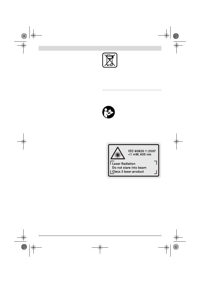
170
|
한국어
2 609 140 773 | (4.12.12)
Bosch Power Tools
維修和服務
維修和清潔
使用附帶的保護套儲存和攜帶儀器。
測量儀器必須隨時保持清潔。
不可以把儀器放入水或其它的液體中。
使用潮濕、柔軟的布擦除儀器上的污垢。不可以使用
洗滌劑或溶劑清潔儀器。
小心地維護、清潔接收透鏡
12
,就好比 您清潔眼鏡
和照相機的透鏡一般。
雖然本公司生產的儀器在出廠之前都經過嚴格的品質
檢驗, 如果仍然發生故障,請將儀器 交給博世電動
工具公司授權的客戶服務處修理。 不可以擅自打開測
量儀器。
查詢和定購備件時,務必提供儀器銘牌上標示的
10 位數物品代碼。
將儀器送修之前,必須先把儀器放入防護套
17
中。
顧客服務處和顧客咨詢中心
本公司顧客服務處負責回答有關本公司產品的修理,
維護和備件的問題。以下的網頁中有爆炸圖和備件的
資料 :
www.bosch-pt.com
博世顧客咨詢團隊非常樂意為您解答
有關本公司產品及附件的問題。
台灣
台灣羅伯特博世股份有限公司
建國北路一段 90 號 6 樓
台北市 10491
電話 : (02) 2515 5388
傳真 : (02) 2516 1176
www.bosch-pt.com.tw
制造商地址 :
羅伯特博世有限公司
營業範圍電動工具
郵箱號碼 100156
70745 Leinfelden-Echterdingen (萊菲登 - 艾希德登)
Deutschland (德國)
處理廢棄物
必須以符合環保要求的方式回收再利用損壞的儀器、
附件和包裝材料。
不可以把損壞的探測儀和蓄電池 / 電池丟棄在一般的
家庭垃圾中!
只針對歐盟國家﹕
根據歐洲的法規 2002 /96 / EG,必
須把不再使用的測量儀器,根據歐洲
的法規 2006 /66 / EG,必須把損耗
的蓄電池 / 電池,分開收集 並且以符
合環保要求的方式回收再利用。
保留修改權。
한국어
안전 수칙
측정공구로 안전한 작업을 하려면 모든
안전 수칙과 지시 사항을 잘 읽고 준수해
야 합니다 . 절대로 측정공구에 나와있는
경고판을 가리지 마십시오 . 이 사용 설
명서를 잘 보관하십시오 .
주의 - 여기에 나와있는 사용장치나 조절장치가 아
닌 것을 사용하거나 다른 방법으로 작업할 경우 위
험한 방사선 노출을 유발할 수 있습니다 .
이 측정공구에는 영문으로 된 경고판이 있습니다 ( 측
정공구의 주요 명칭이 나와있는 그림 중 번호
15
으
로 표시 ).
처음 사용하기 전에 함께 공급되는 한국어로 된 스
티커를 영문 경고판 위에 붙이십시오 .
레이저빔을 사람이나 동물에 향하지 않도록 하고 레
이저빔 안으로 들여다 보지 마십시오 .
이 측정공구
는 IEC 60825
-
1 규격 레이저 등급 2 에 해당하는
레이저빔을 발사합니다 . 이로 인해 일시적으로 타인
의 눈을 안 보이게 할 수 있습니다 .
레이저용 안경을 보안경으로 사용하지 마십시오 .
레
이저용 안경은 레이저빔을 더 잘 보기 위해 사용하
는 것으로 레이저 방사로부터 보호하지 않습니다 .
레이저용 안경을 선글라스로 착용하거나 운전할 때
사용하지 마십시오 .
레이저용 안경을 사용해도 UV
자외선으로부터 완전히 보호할 수 없으며 색상 감별
력이 감소합니다 .
OBJ_BUCH-1444-004.book Page 170 Tuesday, December 4, 2012 1:47 PM
한국어
|
171
Bosch Power Tools
2 609 140 773 | (4.12.12)
측정공구의 수리는 반드시 전문 인력에게 맡기고 , 수
리 정비 시 보쉬 순정 부품만을 사용하십시오 .
그렇
게 함으로서 측정공구의 안전성을 오래 유지할 수 있
습니다 .
레이저 측정공구를 어린이 혼자 사용하지 않도록 하
십시오 .
실수로 다른 사람의 눈을 일시적으로 안 보
이게 할 수 있습니다 .
가연성 유체나 가스 혹은 분진 등 폭발 위험이 있는
곳에서 측정공구를 사용하지 마십시오 .
측정공구에
분진이나 증기를 점화하는 스파크가 생길 수 있습니
다 .
제품 및 성능 소개
사용 설명서를 읽는 동안 측정공구의 그림이 나와있는
접힌 면을 펴 놓고 참고하십시오 .
규정에 따른 사용
본 측정공구는 거리 , 길이 , 높이 및 간격을 측정하고
면적과 체적을 계산하는데 사용해야 합니다 . 측정공구
는 실내와 실외에서 측정하는데 적당합니다 .
제품 사양
디지털 레이저 거리 측정기
GLM 50
Professional
제품 번호
3 601 K72 2..
측정 범위
0.05
-
50 m
A)
측정 정확도 ( 표준 )
±
1.5 mm
B)
최소 표시 단위
1 mm
작동 온도
-
10
°C
...+50
°C
C)
보관 온도
-
20
°C
...+70
°C
상대 습도 , 최대
90 %
레이저 등급
2
레이저 유형
635 nm, <1 mW
레이저빔 직경 (25
°C
의 경우 ) 약
–
10 m 거리에서
–
50 m 거리에서
6 mm
35 mm
자동 꺼짐 기능 작동 ( 대략 경과 후 )
–
레이저
–
측정공구 ( 측정 않을 경우 )
20 s
5 min
배터리
충전용 배터리
2 x 1.5 V LR03 (AAA)
2 x 1.2 V HR03 (AAA)
배터리 수명 약
–
개별 측정
–
연속 측정
10000
D)
2.5 h
D)
EPTA 공정 01/2003 에 따른 중량
0.14 kg
크기
53 x 114 x 30 mm
보호 등급
IP 54 ( 분진 및 튀기는 물에 안전함 )
A) 레이저 광선이 표적면에서 반사되는 정도가 좋을수록 ( 산란하고 반짝이지 않는 경우 ), 레이저 초점이 주위의 명도에 비해 환하면 환할 수록
( 실내 공간 , 해질녁 ) 작동 거리가 길어집니다 . 좋지 않은 조건에서는 ( 태양 광선이 강한 실외에서 측정할 경우 등 ) 표지판이 필요할 수 있습
니다 .
B) 측정공구 후면에서부터 측정 시 . 강한 태양 광선에서 작업하거나 반사 상태가 좋지 않은 표면 등 불리한 조건에서 작업할 때 50 m 의 경
우 최대 오차가
±
10 mm 입니다 . 유리한 조건에서는 오차가
±
0.05 mm/m 입니다 .
C) 연속 측정 기능의 경우 최대 운전 온도는 +40 °C 입니다 .
D) 1.2 V 충전용 배터리의 경우 1.5 V 배터리를 사용했을 경우 보다 측정 횟수가 적습니다 . 나와있는 배터리 수명은 디스플레이 조명을 사용
하지 않고 측정한 경우입니다 .
귀하의 측정공구를 정확히 식별하려면 타입 표시판에 나와있는 일련 번호
13
을 확인하십시오 .
OBJ_BUCH-1444-004.book Page 171 Tuesday, December 4, 2012 1:47 PM
172
|
한국어
2 609 140 773 | (4.12.12)
Bosch Power Tools
제품의 주요 명칭
제품의 주요 명칭에 표기되어 있는 번호는 측정공구의
그림이 나와있는 면을 참고하십시오 .
1
디스플레이
2
측정 버튼
3
면적 , 체적 및 간접 높이 측정 ( 피타고라스 ) 버튼
4
삭제 버튼 / 전원 버튼 **
5
마이너스 버튼
6
기준 레벨 선택 버튼
7
운반용 끈 끼우는 부위
8
플러스 버튼
9
거리 및 연속 측정 버튼
10
배터리 케이스 덮개
11
레이저빔 발사구
12
수신 렌즈
13
일련 번호
14
1/4" 나사
15
레이저 경고판
16
배터리 케이스 덮개 잠금쇠
17
안전 케이스
18
삼각대 *
19
레이저용 안경*
20
레이저 표적판*
*도면이나 설명서에 나와 있는 액세서리는 표준 공급부품에 속
하지 않습니다 .
** 추가 기능을 작동하려면 버튼을 누른 상태로 유지하십시오 .
디스플레이 내용
a
측정치 표시열
b
결과 표시열
c
측정 기능
d
레이저빔 켜짐
e
측정 기준 레벨
f
온도 경고 표시
g
배터리 경고 표시
h
에러 표시
“ERROR”
조립
배터리 끼우기 / 교환하기
측정공구를 작동하려면 알칼리 망간 배터리나충전용 배
터리를 사용하는 것이 좋습니다 .
1.2 V 충전용 배터리를 사용하면 1.5 V 배터리를 사용
하는 것보다 측정 횟수가 적습니다 .
배터리 케이스 덮개
10
을 열려면 잠금쇠
16
을 누르
고 배터리 케이스 덮개를 빼십시오 . 배터리나 충전용
배터리를 끼우십시오 . 이때 배터리 케이스 내면에 나온
것처럼 전극이 제대로 끼워졌는지 확인하십시오 .
배터리나 충전용 배터리를 끼울 때 배터리 케이스에 표
시된 것처럼 전극이 제대로 끼워져 있는지 확인하십시
오 .
디스플레이에 배터리 표시
가 처음으로 나타나면 적
어도 100 회의 개별 측정이 가능합니다 . 연속 측정 기
능은 작동되지 않습니다 .
배터리 표시
가 깜박이면 배터리나 충전용 배터리
를 교환해야 합니다 . 측정이 더 이상 불가능합니다 .
항상 배터리나 충전용 배터리를 모두 동시에 교환해 주
십시오 . 한 제조사의 동일한 용량의 배터리나 충전용
배터리만을 사용하십시오 .
장기간 측정공구를 사용하지 않을 경우에는 배터리
나 충전용 배터리를 측정공구에서 빼십시오 .
오래
저장할 경우 배터리나 충전용 배터리가 부식하거나
저절로 방전될 수 있습니다 .
작동
기계 시동
측정공구가 켜져 있는 상태에서 자리를 비우지 말고,
사용 후에는 측정공구의 스위치를 끄십시오 .
레이저
빔으로 인해 다른 사람의 눈을 일시적으로 안 보이
게 할 수 있습니다 .
측정공구가 물에 젖거나 직사 광선에 노출되지 않도
록 하십시오 .
측정공구를 극심한 온도에서 혹은 온도 변화가 심한
곳에서 사용하지 마십시오 .
예를 들면 측정공구를
자동차 안에 장기간 두지 마십시오 . 온도 변화가 심
한 경우 측정공구를 사용하기 전에 우선 적당한 온
도가 되도록 하십시오 . 극심한 온도에서나 온도 변화
가 심한 환경에서 사용하면 측정공구의 정확도가 떨
어질 수 있습니다 .
측정공구에 강한 충격을 주거나 떨어뜨리지 않도록
하십시오 .
측정공구에 강한 외적인 작용이 가해진
경우 계속 작업하기 전에 반드시 정확도 테스트를 실
시해야 합니다 (“ 거리 측정의 정확도 검사 ”
참조 , 174 면 ).
거리 측정
연속 측정
면적 측정
체적 측정
단일 피타고라스 측정
OBJ_BUCH-1444-004.book Page 172 Tuesday, December 4, 2012 1:47 PM
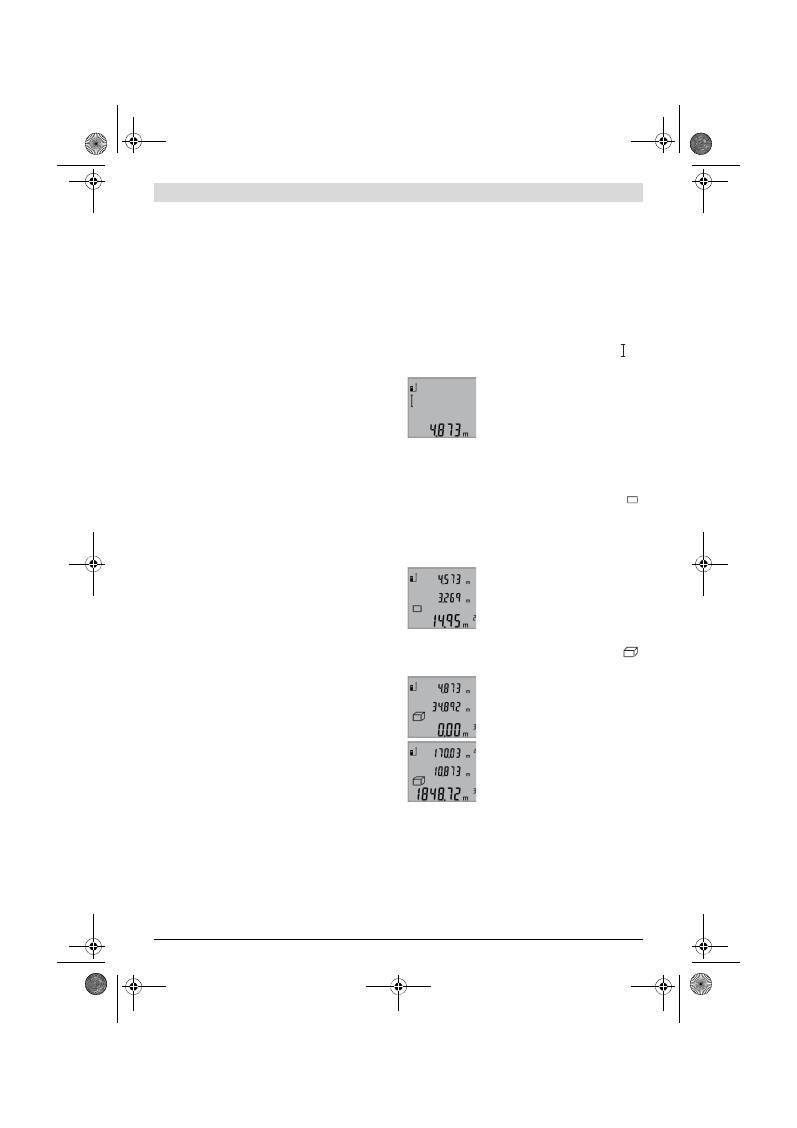
한국어
|
173
Bosch Power Tools
2 609 140 773 | (4.12.12)
스위치 켜기 / 끄기
측정공구를
작동하려면
다음과 같이 할 수 있습니다 :
–
전원 버튼
4
를 누릅니다 : 측정공구의 스위치가 켜지
며 거리 측정 기능으로 설정되어 있습니다 . 레이저
빔이 켜지지 않습니다 .
–
측정 버튼
2
를 누릅니다 : 측정공구와 레이저가 켜집
니다 . 측정공구가 길이 측정 기능으로 설정되어 있
습니다 .
레이저빔을 사람이나 동물에 향하지 않도록 하고, 먼
거리에서라도 레이저빔 안으로 들여다 보지 마십시
오 .
측정공구의
스위치를 끄려면
전원 버튼
4
를 몇 초간 누
르십시오 .
측정공구에 약 5 분간 아무런 버튼도 누르지 않으면 배
터리를 절약하기 위해 측정공구가 자동으로 꺼집니다 .
측정 과정
스위치를 켜고 나서 측정 버튼
2
를 누르면 측정공구는
항상 길이 측정 기능으로 되어 있습니다 . 각 기능 버튼
을 누르면 다른 측정 기능을 설정할 수 있습니다 (“ 측
정 기능 ” 참조 , 173 면 ).
스위치를 켜면 측정용 기준 레벨로 측정공구의 후방 모
서리가 사전 설정되어 있습니다 . 기준 레벨 버튼
6
을
눌러 기준 레벨을 변경할 수 있습니다 (“ 기준 레벨 정
하기 ” 참조, 173 면 ).
기준 레벨을 선택한 측정공구를 벽 등 원하는 측정 시
작점에 대십시오 .
레이저빔을 켜려면 측정 버튼
2
를 짧게 누릅니다 .
레이저빔을 사람이나 동물에 향하지 않도록 하고, 먼
거리에서라도 레이저빔 안으로 들여다 보지 마십시
오 .
레이저빔으로 표적면을 조준합니다. 측정을 실시하려면
측정 버튼
2
를 다시 한번 누르십시오 .
연속 측정 기능의 경우 기능을 선택함과 동시에 측정이
시작됩니다 .
측정치는 일반적으로 0.5 초에서 늦어도 4 초 내에 나
타납니다 . 측정 시간은 거리 , 조명 상태 그리고 목표
면의 반사 정도에 따라 좌우됩니다 . 측정을 마치고 나
면 레이저빔이 자동으로 꺼집니다 .
조준하고 나서 약 20 초가 지나도 측정하지 않으면 배
터리를 절약하기 위해 레이저빔이 자동으로 꺼집니다 .
기준 레벨 정하기 ( 그림 A 참조 )
측정할 때 3 가지 다양한 기준 레벨 중에 선택할 수 있
습니다 :
–
측정공구의 후면 ( 예를 들어 벽에 붙여 사용할 경우 ),
–
측정공구의 전면 ( 예를 들어 책상 가장자리에서 측정
할 경우 ),
–
나사
14
의 중심 ( 예를 들면 삼각대를 사용하여 측정
할 경우 ).
기준 레벨을 선택하려면 디스플레이에 원하는 기준 레
벨이 나타날 때까지 버튼
6
을 누르십시오 . 측정공구의
스위치를 켜면 측정공구의 후면이 기준 레벨로 설정되
어 있습니다 .
디스플레이 조명
디스플레이 조명은 주위의 밝기에 따라 자동으로 켜집
니다 . 디스플레이 조명이 켜진 후에 다른 버튼을 누르
지 않으면 배터리를 보호하기 위해 어두어집니다 .
측정 기능
간단한 거리 측정 ( 그림 B 참조 )
길이 측정을 하려면 디스플레이에 길이 측정 표시 가
나타날 때까지 버튼
9
를 여러번 눌러 주십시오 .
레이저빔을 켜거나 측정하려면 각각
한번씩 측정 버튼
2
를 짧게 누릅니
다 .
측정치는 결과 표시열
b
에 나타납니
다 .
거리 측정을 여러번 연속으로 할 경우 마지막 측정 결
과가 측정치 표시열
a
에 나타납니다 .
면적 측정 ( 그림 C 참조 )
면적 측정을 하려면 디스플레이에 면적 측정 표시
가 나타날 때까지 여러번 버튼
3
을 누르십시오 .
그리고 나서 거리 측정을 한 것과 마찬가지로 길이와
폭을 차례로 측량하십시오 . 두 측정을 하는 동안 레이
저빔이 계속 켜져 있습니다 .
두번째 측정을 마치고 나면 면적이 자
동으로 계산되어 결과 표시열
b
에 나
타납니다 . 개별 측정치는 측정치 표
시열
a
에 보입니다 .
체적 측정 ( 그림 D 참조 )
체적 측정을 하려면 디스플레이에 체적 측정 표시
가 나타날 때까지 버튼
3
을 여러번 누르십시오 .
그리고 나서 거리 측정을 한 것과 마
찬가지로 길이와 폭 그리고 높이를 차
례로 측량하십시오 . 세 측정을 하는
동안 레이저빔이 계속 켜져 있습니다 .
세번째 측정을 마치고 나면 체적이 자
동으로 계산되어 결과 표시열
b
에 나
타납니다 . 개별 측정치는 측정치 표
시열
a
에 보입니다 .
999999 m
3
를 초과하는 수치는 표시될 수 없으며 디
스플레이에
“ERROR”
표시가 나타납니다 . 이 경우
측정하려는 체적을 나누어 개별 측정하고 이 값을 각각
계산하여 더하면 됩니다 .
연속 측정 ( 그림 E 참조 )
연속 측정을 할 경우 측정공구를 목표 물체에 따라 움
직일 수 있습니다 , 이때 측정치는 약 0.5 초 간격으로
경신됩니다 . 예를 들어 벽에서 원하는 간격만큼 멀어지
면서 현재 거리를 계속 읽을 수 있습니다 .
OBJ_BUCH-1444-004.book Page 173 Tuesday, December 4, 2012 1:47 PM
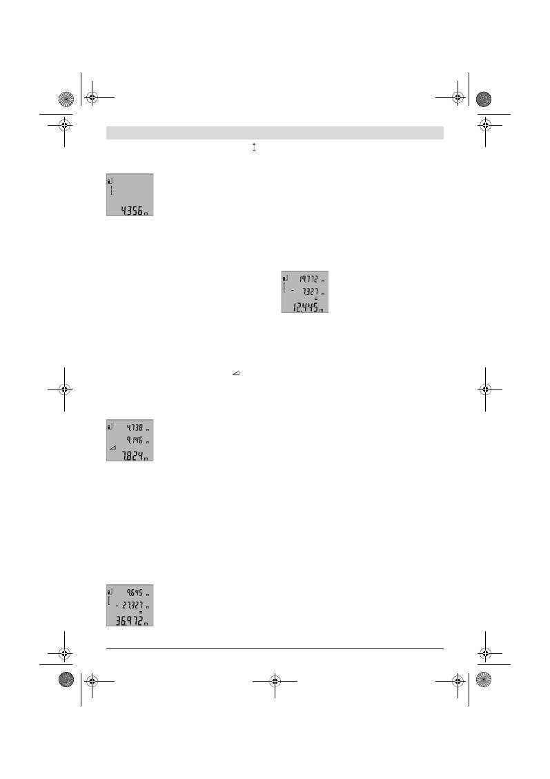
174
|
한국어
2 609 140 773 | (4.12.12)
Bosch Power Tools
연속 측정을 하려면 디스플레이에 연속 측정 표시
가
나타날 때까지 버튼
9
를 누르십시오 . 연속 측정을 시
작하려면 측정 버튼
2
를 누르면 됩니다 .
최근 측정치가 결과 표시열
b
에 나타
납니다 .
측정 버튼
2
를 누르면 연속 측정이
종료됩니다 . 최종 측정치가 결과 표
시열
b
에 보입니다 . 측정 버튼
2
를
다시 누르면 연속 측정이 처음부터 시
작됩니다 .
연속 측정 기능은 5 분 후에 자동으로 꺼집니다 . 최종
측정치가 결과 표시열
b
에 나타납니다 .
간접 높이 측정 / 단일 피타고라스 측정
( 그림 F 참조 )
간접 높이 측정은 레이저빔 구간에 장애물이 있거나 표
적면을 반사체로 사용할 수 없기 때문에 직접 거리 측
정이 불가능한 경우 사용하십시오 . 각 측정에 필요한
각도가 정확히 직각인 경우에만 정확한 결과치를 얻을
수 있습니다 ( 피타고라스 정의 ).
이때 측정의 기준점 ( 측정공구의 후면 등 ) 이 측정 과
정 동안 모든 개별 측정 시 정확히 동일한 위치에 있어
야 합니다 .
개별 측정을 하는 동안 레이저빔은 켜져 있습니다 .
디스플레이에 단일 피타고라스 측정 표시
가 나타
날 때까지 버튼
3
을 여러번 누르십시오 .
길이 측정의 경우와 마찬가지로 구간
“1”
과
“2”
를 이 차례대로 측정하십시오 . 이때 구간
“1”
과 측
정하려는 구간
“X”
사이가 직각이어야 합니다 .
마지막 측정을 마치고 나면 구하려는
구간
“X”
값이 결과 표시열
b
에
나타납니다 . 개별 측정치가 측정치 표
시열
a
에 보입니다 .
측정치 삭제하기
버튼
4
를 짧게 누르면 모든 측정 기능을 통해 최근 산
출했던 각각의 측정치가 삭제됩니다 . 버튼을 반복적으
로 짧게 누르면 개별 측정치가 반대 순서로 삭제됩니다 .
측정치 더하기
측정치를 더하려면 우선 임의로 측정을 실시하십시오 .
그리고 나서 플러스 버튼
8
을 누르면 디스플레이에 확
인하도록
“+”
가 보입니다 .
체적이나 면적을 더하려면 첫번째 측정을 마치고 나서
플러스 버튼
8
을 누르십시오 . 디스플레이에 확인하도
록 체적
-
/ 면적 기호 왼쪽에
“+”
가 보입니다 .
그리고 나서 두번째 측정을 실시하십시오 .
두 측정의 합계를 계산하려면 다시 한
번 플러스 버튼
8
을 누르십시오 . 계
산치가 측정치 표시열
a
에 보이고 ,
합계가 결과 표시열
b
에 나타납니다 .
합계를 계산한 후에 , 측정하기 전에 각각 플러스 버튼
8
을 누르면 이 값에 다른 측정치를 더할 수 있습니다 .
더하기 기능에 관한 사항 :
–
거리길이 , 면적 및 체적 측정치는 서로 더할 수 없습
니다 . 예를 들어 길이와 면적 측정치를 더하기 위해
플러스 버튼
8
을 누르면 디스플레이에 잠깐
“ERROR”
표시가 나타납니다 . 그리고 나서 측정
공구는 최근에 사용되었던 측정 기능으로 바뀝니다 .
–
각 측정 결과(체적치 등)가 더해지며, 연속 측정의 경
우 결과 표시열
b
에 나와있는 측정치가 더해집니다 .
측정치 표시열
a
에 나와있는 개별 측정치를 더하는
것은 불가능합니다 .
측정치 빼기
측정치의 뺄셈을 하려면 마이너스
버튼
5
를 누릅니다 , 디스플레이에 확
인용으로
“
-
”
표시가 나타납니
다 . 다음 단계는 “ 측정치 더하기 ”
의 내용과 상응합니다 .
사용방법
일반 사항
측정하는 동안 수신 렌즈
12
와 레이저빔 발사구
11
이
가려져 있어서는 안됩니다
연속 측정 기능인 경우를 제외하고는 측정 중에 측정공
구를 움직이면 안됩니다 . 그러므로 측정공구를 가능한
한 단단한 벽면이나 표면에 대십시오 .
측정 범위에 미치는 영향
측정 범위는 조명 상태와 표적면의 반사 특성에 따라
좌우됩니다 . 실외에서 작업할 때나 햇볕이 강한 조건에
서 측정 작업을 할 때 레이저빔이 더 잘 보이도록 하려
면 레이저용 안경
19
( 별매 액세서리 ) 이나 레이저 표
적판
20
( 별매 액세서리 ) 를 사용하거나 , 혹은 표적면
을 햇볕으로부터 가리십시오 .
측정 결과에 미치는 영향
다양한 표면에 측정할 경우 물리적인 이유로 인해 측정
오류가 생길 수 있습니다 . 예를 들면 :
–
투명한 표면 ( 유리나 물 등 ),
–
반짝이는 표면 ( 폴리싱한 금속 , 유리 등 ),
–
다공성 표면 ( 단열재 등 ),
–
구조물 표면 ( 조면 플라스터 , 자연석 등 ).
이러한 표면에 작업할 때 경우에 따라 레이저 표적판
20
( 별매 액세서리 ) 를 사용하십시오 .
비스듬히 표적면에 조준한 경우 측정 에러가 생길 수
있습니다 .
또한 온도가 상이한 공기층 혹은 간접적인 반사 경우에
도 측정 결과에 지장이 있을 수 있습니다 .
거리 측정의 정확도 검사
거리 측정의 정확도는 다음과 같이 확인할 수 있습니다 :
–
길이가 정확히 알려진 약 1 내지 10 m 사이의 변하
지 않는 ( 방 너비나 문 크기 등 ) 측정 구간을 선택
OBJ_BUCH-1444-004.book Page 174 Tuesday, December 4, 2012 1:47 PM
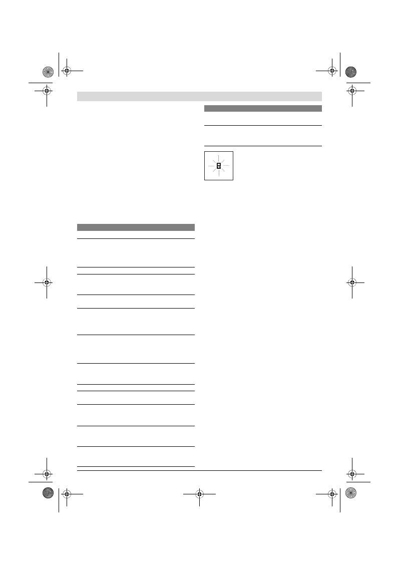
한국어
|
175
Bosch Power Tools
2 609 140 773 | (4.12.12)
합니다 . 측정 구간은 실내이어야 하며 측정하려는 표
적면은 매끄럽고 반사가 잘 되는 것이어야 합니다 .
–
이 구간을 10 회 연속 측정하십시오 .
개별 측정의 오차는 평균값에서
±
2 mm 이하이어야
합니다 . 추후에 정확도를 비교할 수 있도록 측정치를 기
록해 놓으십시오 .
삼각대를 사용한 작업 ( 별매 액세서리 )
특히 먼 거리를 측정할 때 삼각대를 사용하는 것이 필
요합니다 . 측정공구를 1/4" 나사
14
를 사용하여 삼각
대
18
의 순간 교환 플레이트에 끼우거나 시중에서 구
매가 가능한 카메라 삼각대에 끼우십시오 . 그리고 나서
이를 순간 교환 플레이트의 고정 나사를 사용하여 고정
하십시오 .
기준 레벨 버튼
6
을 눌러 삼각대를 사용할 경우의 레
벨에 적당하게 맞추십시오 ( 기준 레벨 나사 ).
고장의 원인과 해결 방법
측정공구는 각 측정 시 정확한 기능을
감독합니다 . 하자가 확인된 경우 디스
플레이에 옆에 나와있는 표시만 깜박입
니다 . 이러한 경우 혹은 상기에 소개한
고장의 해결 방법으로 문제를 해결할
수 없으면 측정공구를 대리점을 통해 보쉬 서비스 센터
로 보내 주십시오 .
보수 정비 및 서비스
보수 정비 및 유지
반드시 측정공구를 함께 공급된 안전 케이스에 넣어 보
관하고 운반하십시오 .
항상 측정공구를 깨끗이 유지하십시오 .
측정공구를 물이나 다른 액체에 넣지 마십시오 .
물기있는 부드러운 천으로 오염된 부위를 깨끗이 닦으
십시오 . 세척제나 용제를 사용하지 마십시오 .
특히 수신 렌즈
12
는 안경이나 카메라 렌즈를 다루듯
이 조심스럽게 관리하십시오 .
세심한 제작과 검사에도 불구하고 측정공구가 불량한
경우가 있다면 보쉬 지정 전동공구 서비스 센터에 수리
를 의뢰하십시오 . 측정공구를 직접 열어 분해하지 마십
시오 .
문의 사항이 있거나 스패어 부품을 주문할 때 반드시
측정공구의 타입 표시판에 적힌 10 자리의 제품 번호를
알려 주십시오 .
수리를 해야 할 경우 측정공구를 안전 케이스
17
에 넣
어 보내 주십시오 .
보쉬 AS 및 고객 상담
보쉬는 귀하의 제품 및 수리에 관한 문의를 받고 있습
니다 .
AS 센터 정보 및 제품에 대한 고객 상담은 하기 고객
콜센터 및 이메일 상담을 이용해주시기 바랍니다 .
고객 콜센터 : 080-955-0909
이메일 상담 :
Bosch-pt.hotline@kr.bosch.com
한국로버트보쉬 ( 주 )
경기도 용인시 기흥구 보정동 298 번지
www.bosch-pt.co.kr
원인
해결 방법
온도 경고 표시 (
f
) 가 깜박이고 , 측정이 불가능합니다
측정공구가 운전 온도
-
10
°C
에서 +50
°C
범위
밖입니다 ( 연속 측정 기능 경우
+40
°C
까지 ).
측정공구가 작동 온도
에 달할 때까지 기다리
십시오
디스플레이에 “ERROR” 표시가 보일 경우
측정 단위가 상이한 측정치를 더
하거나 빼려고 합니다
동일한 측정 단위의 측
정치만을 더하거나 빼
십시오
레이저빔과 표적 간의 각도가 좁
습니다 .
레이저빔과 표적 간의
각도를 넓힙니다
표적면이 지나치게 반짝이거나
( 거울 등 ) 너무 약하고 ( 검정색
소재 ) 혹은 주변의 조명이 너무
강합니다 .
레이저 표적판
20
( 별
매 액세서리 ) 를 사용
하십시오
레이저빔 발사구
11
이나 수신
렌즈
12
를 흐려진 경우 ( 예로
급격한 온도 변화로 인해 ).
부드러운 천으로 레이
저빔 발사구
11
이나 수
신 렌즈
12
를 닦아 말
리십시오
측정된 수치가
999999 m/m
2
/m
3
이상입니
다 .
측정을 나누어서 하십
시오
측정 결과가 이상할 경우
표적면이 제대로 반사하지 않습
니다 ( 물이나 유리의 경우 ).
표적면을 덮습니다
레이저빔 발사구
11
이나 수신
렌즈
12
가 가려져 있습니다 .
레이저빔 발사구
11
이
나 수신 렌즈
12
가 가
려지지 않도록 합니다 .
기준 레벨이 잘못 설정되었습니
다
기준 레벨을 측정하려
는 것에 맞게 선택하십
시오
레이저빔 구간에 장애가 있습니
다
레이저 초점이 완전히
표적면에 있어야 합니
다
표시기가 변경되지 않거나 버튼을 눌러도 측정공구가 반
응하지 않을 경우
소프트웨어 에러
배터리를 뺐다가 다시
끼운 다음, 측정공구를
다시 작동하십시오 .
원인
해결 방법
OBJ_BUCH-1444-004.book Page 175 Tuesday, December 4, 2012 1:47 PM
176
|
한국어
2 609 140 773 | (4.12.12)
Bosch Power Tools
처리
측정공구 , 액세서리 및 포장 등은 친환경적인 방법으로
재활용될 수 있도록 분류하십시오 .
측정공구와 배터리 팩 / 배터리를 가정용 쓰레기로 처리
하지 마십시오 !
EU 국가만 해당 :
측정공구 폐품에 관한 EU 지침
2002/96/EG 에 따라 , 그리고 EU 지
침 2006/66/EG 에 따라 고장나거나
소모된 배터리 팩 / 배터리는 분리 수거
하여 환경 친화적인 방법으로 재활용하
도록 해야 합니다 .
위 사항은 사전 예고 없이 변경될 수도 있습니다 .
OBJ_BUCH-1444-004.book Page 176 Tuesday, December 4, 2012 1:47 PM
عربي
|
177
Bosch Power Tools
2 609 140 773 | (4.12.12)
دق اهنأ نم مغبلار سايقلا ةدعر للخ يأ ثودح دني
بجوت ةديدي تارابتخا تزاتجاو ةقئاف ةيانعر تعنص
ددعلل شور ةكبش ةلاكو ةمدخ زكبم عف اهحيلصت
.كسفنر سايقلا ةدي حتفت لا .ةيئاربهكلا
بشعلا بتابملار فنصلا مقر بكذ يروبض لكشر یجبي
لاسرإ دنيو ةراشتسلاا دني سايقلا ةدي زابط ةحئلا بسح
.رايغلا عطق تايبلط
ةبيقح عف اهحيلصت بجوت لاح عف سايقلا ةدي لسبت
.
17
ةياقولا
مادختسلاا ةروشمو نئابزلا ةمدخ
ةنايصو حيلصت ددصر مكتلئسأ ىلي نئارزلا ةمدخ زكبم بيجي
موسبلا ىلي بثعي .رايغلا عطق صخي امر اضيأو جتنملا
:عقومر رايغلا عطق ني تامولعملا ىليو ةددمملا
www.bosch-pt.com
ةكبشر مادختسلاا ةروشم ةقبف روبس عياود نم نوكيس
.اهعراوتو انتاجتنم ني ةلئسلأا صوصخر مكدياست نأ شور
نامضلا رومأر قّلعتي امر صتخملا بجاتلا یلإ هجوتلا یجبي
.رايغلا عطق نيمأتو حيلصتلاو
ةيئابرهكلا ةدعلا نم صلختلا
ةقيبطر فيلغتلاو عراوتلاو سايقلا ةدي نم صلختلا بجي
.عينصتلا ةدايلإ ةلراقلا تايافنلا قيبط ني ةئيبلار ةفصنم
تايافنلا عف تايراطبلا/مكابملاو سايقلا ددي مبت لا
!ةيلزنملا
:طقف يبورولأا داحتلاا لودل
بجي
2002/96/EG
عرورولأا هيجوتلا بسح
ةحلاص بيغلا سايقلا ددي عمج متي نأ
عرورولأا هيجوتلا بسحو ،لامعتسلال
/مكابملا عمج متي نأ بجي
2006/66/EG
یلي ةكلهتسملا وأ ةفلاتلا تايراطبلا
ةفصنم ةقيبطر اهنم صلختلا متيل دابفنا
.بيودتلا قيبط ني ةئيبلار
.تلايدعتلا لاخدإ قحب ظفتحن
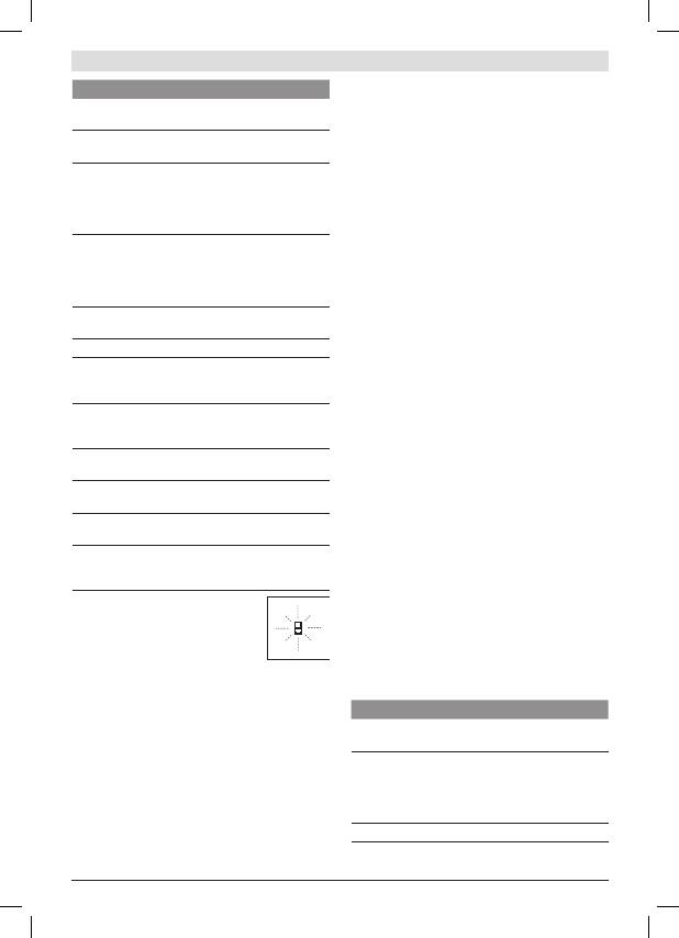
178
|
عربي
2 609 140 773 | (4.12.12)
Bosch Power Tools
سايقلا لاجم یلع ةرثؤم لماوع
ساكعنا تافصاومرو ةءاضلإا ةلاحر سايقلا لاجم قلعتي
ةحولو )عراوت(
19
رزيللا ةيؤر تاراظن لمعتسا .فدهلا حطس
رزيللا عاعشا ةيؤر ةيناكمإ نيسحتل )عراوت(
20
رزيللا نيشنت
سمشلا ةعشأ عشت امدني وأ جراخلا عف لمعلا ءادأ دني
.فدهلا حطس یلي لظلا بفوت نمأ وأ ةوقر
سايقلا ةجيتن یلع ةرثؤم لماوع
تابيثأتلا ساسأ یلي ةئطاخ تاسايق ینثتست نأ نكمي لا
:اهنمض نم .ةفلتخم حوطس سايق دني ةيئايزيفلا
−
،)ءاملا ،جاجزلا :لاثم( ةفافشلا حوطسلا
−
،)جاجزلا ،لوقصملا ندعملا :لاثم( ةسكاعلا حوطسلا
−
،)ةلزاعلا داوملا :لاثم( ةيماسملا حوطسلا
−
بجحلا ،نشخلا ناردجلا صج :لاثم( ةيبيكبتلا حوطسلا
.)ععيبطلا
حوطسلا هذه یلي )عراوت(
20
رزيللا نيشنت ةحول لمعتسا
.ةروبضلا دني
فدهلا حوطس یلي ةئطاخ سايق تايلمي متت نأ زوجي امك
.لئام لكشر اهنيشنت مت عتلا
وأ ةرابحلا ةفلتخملا ةيئاوهلا تاقبطلل اضيأ زوجي امك
یليبثؤت نأ بشابم بيغ لكشر لبقتست عتلا تاساكعنلال
.سايقلا ةميق
تافاسملا سايق ةقد صحف
:ةيلاتلا ةقيبطلار تافاسملا سايق ةقد صحفت نأ كنكمي
−
،م
10
یلإ
1
نم اهردق ةبيغتم بيغ سايق ةفاسم بتخا
ضبي :لاثم( قيقد لكشر اهلوطر ملي یلي نوكت نأ یلي
ةفاسم نوكت نأ بجي .)بابلا ةحتف ضبي وأ ةفبغلا
سلمأ نيشنتلا حطس نوكي نأو لخادلا عف سايقلا
.ديج لكشر سكايو
−
.ةربكتم تابم
10
ةفاسملا سيقت نأ عغبني
یطسولا ةميقلا ني ةيدبفلا تاسايقلا توافت غلبي نأ زوجي
نأ عيطتست عكل ،تاسايقلا لجس .مم
± 2
هاصقأ رادقمر
.ةقحلا ةينمز ةبتفر ةقدلا نراقت
)عباوتلا نم( مئاوقلا يثلاثلا بصنملا ةطساوب لمعلا
بصنملا مادختسا صاخ لكشر ةبيبكلا تافاسملا بلطتت
ةصور
¼
ةبلوللا نانسأر سايقلا ةدي زكر .مئاوقلا عثلاثلا
مئاوقلا عثلاثلا بصنملار بييغتلا ةعيبسلا ةحيفصلا یلي
14
ةطساور اهتيبثت مكحأ .لوادتم بيوصت تلاآ بصنمر وأ
18
.بييغتلا ةعيبسلا ةحيفصلار تيبثتلا بلول طرر
مئاوقلا عثلاثلا بصنملا عم سايقلل دانسلاا یوتسم طبضا
نانسأ ،دانسلاا یوتسم(
6
رزلا یلي طغضلا للاخ نم
.)ةبلوللا
تاءارجلإاو بابسلأا – ءاطخلأا
ببسلا
تاءارجلإا
ريغ سايقلا ،قفخي
(f)
ةرارحلا ةجرد نم ريذحتلا
نكمم
جراخ سايقلا ةدي عقت
ليغشتلا ةرابح ةجردلاجم
یلإ
–10 °C
نم ةغلابلا
سايقلا ةفيظور(
+ 50 °C
.)
+ 40 °C
دح یلإ بمتسملا
ةدي لصت نأ یلإ بظتنا
ةرابح ةجرد یلإ سايقلا
ليغشتلا
ةشاشلا یلع
“ERROR”
رشؤملا
ببسلا
تاءارجلإا
ميق تحبط/تعمج
ةفلتخم تادحور تاسايق
تاسايق ميق حبطا/عمجا
طقف تادحولا سفنر
رزيللا عاعشا نير ةيوازلا
.ادج ةداح فدهلاو
عاعشا نير ةيوازلا ببك
فدهلاو رزيللا
سكعي فدهلا حطس
)لاثم ةآبم( دئاز لكشر
شامق( فيعض لكشر وأ
ةءاضإ وأ )لاثم دوسأ
.ادج ةديدش ناكملا
نيشننت ةحول مدختسا
)عراوت(
20
رزيللا
11
رزيللا عاعشا جبخم
12
لابقتسلاا ةسدي وأ
ببسر( راخبلار تستكا
ةرابح تاجرد تابيغت
.)لاثم ةعيبس
جبخم ففجو حسما
ةسدي وأ
11
رزيللا عاعشا
ةطساور
12
لابقتسلاا
ةيبط شامق ةعطق
نم ببكأ ةروسحملا ةميقلا
.
3
م/
2
م/م
999 999
تاوطخ یلإ باسحلا مسقي
ةتقؤم
ةلوقعم ريغ سايقلا ةجيتن
سكعي لا فدهلا حطس
،ءاملا :لاثم( حضاو لكشر
.)جاجزلا
فدهلا حطس یطغي
11
رزيللا عاعشا جبخم
12
لابقتسلاا ةسدي وأ
.ةاطغم
ةيطغت مدي یلي ظفاح
وأ
11
رزيللا عاعشا جبخم
12
لابقتسلاا ةسدي
دانسا یوتسم طبض مت
ئطاخ
دانسلاا یوتسم طبضا
سايقلل مئلاملا
عاعشا راسمر قئاي دجوي
رزيللا
رزيللا ةطقن زكتبت نأ بجي
.فدهلا حطس یلي اهلماكر
ريغ لكشب بواجتت سايقلا ةدع وأ ريغتي لا رشؤملا
رزلا یلع طغضلا دنع عقوتم
تايجمببلا عف أطخ
ةدي لغشو تايراطبلا عزنا
دعر یبخأ ةبم سايقلا
.اهبيكبت ةدايإ
لكر لمعلا ةملاس سايقلا ةدي بقابت
طقف رواجملا زمبلا قفخيسو .سايق ةيلمي
وأ ةلاحلا هذه عفو .للخلا فشك لاح عف
هلايأ ةدياسملا تاءابجلإا كدياست مل نإ
بجاتلا ببي سايقلا ةدي لسراف ،أطخلا ةلازإر
.شور ةكبش نئارز ةمدخ زكبم یلإ
ةمدخلاو ةنايصلا
فيظنتلاو ةنايصلا
.طقف ةقفبملا ةياقولا ةبيقحر سايقلا ةدي لقناو نزخ
.سايقلا ةدي ةفاظن یلي امئاد ظفاح
.لئاوسلا نم اهبيغ وأ ءاملا عف سايقلا ةدي سطغت لا
لا .ةبطرو ةيبط جيسن ةعطق ةطساور خاسولأا حسما
.ةلحملا داوملا وأ فيظنتلا داوم لمعتست
ةقيبط سفنرو صاخ لكشر
12
لابقتسلاا ةسدعر ینتعي
.بيوصتلا ةبيماك ةسدي وأ تاراظنلا اهر لماعت عتلا ةيانعلا
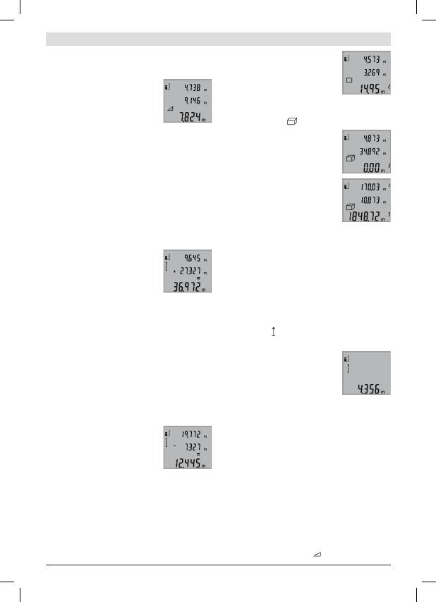
عربي
|
179
Bosch Power Tools
2 609 140 773 | (4.12.12)
متخ دعر علآ لكشر ةحاسملا بسحت
بطسر ضبعتو ةيناثلا سايقلا ةيلمي
ةدبفملا تاسايقلا ميق ضبعت .
b
ةجيتنلا
.
a
تاسايقلا بطسأر
)
D
ةروصلا عجارت( موجحلا سايق
یلإ ،موجحلا تاسايق رايتخا لجأ نم
3
رزلا یلي طغضلا ربك
.ةشاشلا یلي
موجحلا تاسايق بشؤم ضبعي نأ
ضبعلاو لوطلا كلذ دعر ساقي
سفنر ضعبلا مهضعر ولت عافترلااو
عاعش یقبي .لاوطلأا سايق ةقيبط
سايقلا تايلمي نير ليغشتلا ديق رزيللا
.ثلاثلا
ةيلمي متخ دعر علآ لكشر مجحلا بسحي
.
b
ةجيتنلا بطسر ضبعيو ةثلاثلا سايقلا
بطسأر ةدبفملا تاسايقلا ميق ضبعت
.
a
تاسايقلا
ضبعيو ،
3
م
999 999
یلي ديزت عتلا ميقلا ضبي نكمي لا
یلي هسايق بوغبملا مجحلا مسق .
“ERROR”
ةشاشلا یلي
مث دابفنا یلي اهميق بسحت عكل ،ةدبفم سايق تايلمي
.اهعمجت
)
E
ةروصلا عجارت( رمتسم سايق
ءابجإ دني فدهلل ةبسنلار سايقلا ةدي كيبحت نكمي
سايقلا ةميق حيحصت متيس هنأ املي ،بمتسملا سايقلا
نيعم رادج ني دعتبت نأ كنكمي هنأ يأ .اث
0,5
لك ةيلاحلا
علاحلا دعبلا أبقت نأ كنكميسو بوغبملا دعبلا دح یلإ
.امئاد
،ةبمتسملا تاسايقلا رايتخا لجأ نم
9
رزلا یلي طغضلا ربك
.ةشاشلا یلي ةبمتسملا تاسايقلا بشؤم ضبعي نأ یلإ
.بمتسملا سايقلا ةيلمعر ءدبلل
2
سايقلا رز یلي طغضا
بطسر ةيلاحلا سايقلا ةميق ضبعت
.
b
ةجيتنلا
للاخ نم بمتسملا سايقلا ءاهنإ متي
ةميق ضبعت .
2
سايقلا رز یلي طغضلا
يدؤي .
b
ةجيتنلا بطسر ةبيخلأا سايقلا
یلإ یبخأ ةبم
2
سايقلا رز یلي طغضلا
.ةديدج ةبم بمتسملا سايقلا ءدر
ةميق یقبت .علآ لكشر د
5
دعر بمتسملا سايقلا أفطي
.
b
ةجيتنلا بطسر ةضوبعم ةبيخلأا سايقلا
عجارت( طيسب ثروغاثيف سايق / رشابم ريغ عافترا سايق
)
F
ةروصلا
داعرلأا سايقل بشابم بيغ لكشر عافترلاا سايق مدختسي
قيعيس قئاي كانه نلأ بشابم لكشر اهسايق نكمي لا عتلا
لصحتس .سكاعك نيشنت حطس بفوت مدعل وأ عاعشلا راسم
ةمئاقلا اياوزلا یلي تظفاح نإ طقف ةميلسلا جئاتنلا یلي
.)ثروغاثيف( سايق ةيلمي لكر ةرولطملا
:لاثم( سايقلا ةيلمعر ةيعجبملا ةطقنلا ءاقر یلي صبحا
یدل امامت ناكملا سفنر )سايقلا ةدعل ةيفلخلا ةفاحلا
.ةدحاولا سايقلا ةيلمي نمض ةدبفملا تاسايقلا عيمج
سايقلا تايلمي نير ليغشتلا ديق رزيللا عاعش یقبي
.ةيدبفلا
بشؤم ةشاشلا یلي ضبعي نأ یلإ
3
رزلا یلي طغضلا ربك
. طيسبلا ثروغاثيف سايق
لاوطلأا سايق ةقيبط سفنر
“2”
و
“1”
ناتفاسملا ساقت
نير ةمئاق ةيواز دوجو یلي صبحا .لسلستلا اذهرو
.
“X”
ةرولطملا ةفاسملاو
“1”
ةفاسملا
ةجيتنلا ضبعت سايقلا ةيلمي متخ دعر
بطس عف
“X”
ةرولطملا ةفاسملا ني
، ةدبفملا تاسايقلا ميق امأ .
b
ةجيتنلا
.
a
سايقلا ميق بطسأر ضبعتف
سايقلا ميق حسم
لكر ةبيخلأا ةدبفملا سايقلا ةميق حسمت نأ كنكمي
.ةلهول
4
رزلا یلي طغضلا للاخ نم تاسايقلا فئاظو
نم سكاعملا لسلستلار ةدبفملا تاسايقلا ميق حسمتو
.رزلا یلي ربكتم لكشر ةلهول طغضلا للاخ
تاسايقلا ميق عمج
سايق ةيلمعر موقت نأ عغبني ،سايقلا ميق عمجر موقت عكل
“+”
ةشاشلا یلي ضبعي .
8
دئازلا رز كلذ دعر طغضا .ام
.ديكأتلل
لوأ دعر
8
دئازلا رز طغضي ،حوحطسلا وأ ماجحلأا عمجت عكل
راسي یلي
“+”
ةشاشلا یلي ضبعي .اهمتخ مت سايق ةيلمي
.حوطسلا/ماجحلأا زمر
.كلذ دعر ةيناث سايق ةيلمعر مق
لجأ نم
8
دئازلا رز یلي یبخأ ةبم طغضا
سايقلا عتيلمي عومجم یلي لوصحلا
بطسأ عف باسحلا ةيلمي ضبعت .نيتنثلاا
عف ضبعتف ةجيتنلا امأ ،
a
سايقلا ميق
.
b
ةجيتنلا بطس
دعر ةجيتنلا هذه یلإ یبخأ تاسايق ميق فيضت نأ كنكمي
لبق
8
دئازلا رز یلي ةبم لك طغضلا طبشر ،عومجملا باسح
.سايق ةيلمي لك
:عمجلا تايلمعل ةبسنلار تاظحلام
−
اهضعر عم موجحلاو حوطسلاو لاوطلأا ميق عمج نكمي لا
هنإف ،لاثم حطس ةميق عم لوط ةميق عمج مت نإ .ضعبلا
ةظحلل
8
دئازلا رز یلي طغضلا دني ةشاشلا یلي بهظي
ةفيظو یلإ كلذ دعر سايقلا ةدي لقتنتو .
“ERROR ”
.ةلاعفلا ةبيخلأا سايقلا
−
امأ ،)لاثم مجح ةميق( دحاو سايق ةجيتن ةبم لك عمجت
ةضوبعملا سايقلا ةميق عمجتف بمتسملا سايقلا دني
ةدبفم تاسايق ميق عمج نكمي لا .
b
ةجيتنلا بطس عف
.
a
تاسايقلا ميق بطسأ نم
تاسايقلا ميق حرط
رز یلي طغضي تاسايقلا ميق حبطل
“–”
ةراشإ ةشاشلا یلي ضبعت ،
5
صقانلا
عمج“ قراطت ةيلاتلا تاءابجلإا .ديكأتلل
.”تاسايقلا ميق
لغش تاظحلام
ةماع تاظحلام
عاعشا جبخمو
12
لابقتسلاا ةسدي ةيطغت متي نأ زوجي لا
.سايقلا ةيلمي ءابجإ دني
11
رزيللا
اديام( سايقلا ةيلمي ءانثأ سايقلا ةدي كيبحت زوجي لا
سايقلا ةدي نكر لضفي كلذل ،)بمتسملا سايقلا ةفيظور
.ناكملإا ردق تراث دانسا وأ زاكترا حطس یلي
Оглавление
- ةمدخلاو ةنايصلا
- ليغشتلا
- بيكرتلا
- ناملأا تاميلعت
- سیورس و تبقارم
- بصن
- ینمیا یاه یئامنهار
