Kaiser EA64..: instruction
Class: Household, kitchen appliances, electronics and equipment
Type: Hood
Manual for Kaiser EA64..
USER MANUAL
GEBRAUCHSANWEISUNG
ИНСТРУКЦИЯ ПО ОБСЛУЖИВАНИЮ И ЭКСПЛУАТАЦИИ
USER MANUAL
GEBRAUCHSANWEISUNG
ИНСТРУКЦИЯ ПО ОБСЛУЖИВАНИЮ И ЭКСПЛУАТАЦИИ
COOKER HOOD
DUNSTABZUGSHAUBE
КУХОННЫЙ ВОЗДУХООЧИСТИТЕЛЬ
DEAR CUSTOMERS,
We are convinced that you have made a right choice. This
product which satisfies the high quality demands and
corresponds to world comprehensive standards realizes your
cooker hood, and his modern appearance which has been
developed by the best European designers will decorate your
kitchen splendidly.
We ask you to read the operating instructions before usage
thoroughly. The consideration of recommendations protects
you from possible inconveniences which can appear as a
result of the wrong use of the
, and allows you to reduce
the consumption of electric energy. If the use corresponds to
the present operating instructions, the
will bring you a
lot of pleasure for a long time.
Our cooker hoods correspond to the main demands of the
security, hygiene and environment protection, according to
the directives of the EU which is confirmed with certificates
DIN ISO 9001, ISO 1400, according to the norms counting
within the frames of the EU, they also correspond to the
Gosstandart of Russia, standards of the CIS, which is
confirmed with the corresponding certificates.
With the thoughts of a constant improvement of the quality of
our
the changes in design and equipment which
lead only to positive changes of the technical qualities are
reserved by the manufacturer.
We wish you an effective use of
.
Yours faithfully
We Inform you that our devices which are the object of the
present operating instructions are precertain exclusively
for the domestic use.
hood
hood
hood
our
cooker hoods
the cooker
of
firm
OLAN-Haushaltsgeräte
Berlin Germany
thank you for purchasing this Kaiser product.
EN
2
2
УВАЖАЕМЫЙ ПОКУПАТЕЛЬ
,
благодарим Вас за приобретение нашей техники.
Мы уверены, что Вы сделали правильный выбор.
Данный продукт удовлетворяет самым высоким
требованиям и отвечает мировым стандартам, его
со в р ем е н н ы й в и д , р а з р а б о т а н н ы й л у ч ш и м и
европейскими дизайнерами, великолепно украсит Вашу
кухню.
Просим Вас внимательно прочитать инструкцию по
обслуживанию и эксплуатации до пуска устройства.
Соблюдение содержащихся в ней рекомендаций
защитит Вас от возможных неприятностей при
н е п р а в и л ь н о й
э к с п л у а т а ц и и
к у х о н н о г о
воздухоочистителя, а также позволит Вам уменьшить
расход электроэнергии. Если эксплуатация
бу д ет со о т в ет с т во в а т ь
настоящей инструкции, наше
будет
радовать Вас долгое время.
Наши кухонные воздухоочистители полностью
соответствуют основным требованиям безопасности,
гигиены и защиты окружающей среды, согласно
директивам Европейского Союза, что подтверждено
сертификатами
1400, в
соответствии с настоящими нормами, действующими
на территории Европейского сообщества, а также
полностью отвечают всем требованиям Госстандарта
России и стандартов других стран СНГ, что
подтверждается сертификатами соответствия.
С мыслью о дальнейшем повышении технических и
э к с п л у а т а ц и о н н ы х х а р а к т е р и с т и к н а ш и х
воздухоочистителей мы оставляем за собой право на
внесение изменений в дизайн и устройство, влияющих
только положительно на потребительские качества и
свойства продукта.
Желаем Вам эффективного пользования
нашей фирмы.
Уважающий Вас
Информируем, что наши приборы, являющиеся
предметом настоящей Инструкции, предназначены
исключительно для домашнего пользования.
кухонного
воздухо оч и с т и т ел я
устройство
кухонным
воздухоочистителем
DIN ISO 9001, ISO
OLAN-Haushaltsgeräte
Berlin Germany
3
DE
RU
LIEBE KUNDIN, LIEBER KUNDE,
wir danken Ihnen für den Erwerb unserer Technik.
Wir sind überzeug, dass Sie eine richtige Wahl getroffen
haben. Dieses Produkt, das die hohen Forderungen zur
Qualität befriedigt und weltumfassenden Standards
entspricht, verwirklicht Ihre Dunstabzugshaube, und
modernes Aussehen, das von besten europäischen Designer
entwickelt worden ist, wird Ihre Küche prächtig schmücken.
Wir bitten Sie die Bedienungsanleitung vor der Nutzung
aufmerksam zu lesen. Die Beachtung von Empfehlungen
schützt Sie von eventuellen Unannehmlichkeiten, die als
Folge
der falschen Nutzung de
auftreten können, und ermöglicht Ihnen den Verbrauch von
Elektroenergie zu reduzieren. D
bringt
Ihnen viel Vergnügen auf lange Zeit, wenn der Gebrauch der
vorliegenden Bedienungsanleitung entsprechen wird.
U n s e re D u n s t a b z u g s h a u b e n e n t s p re c h e n d e n
Hauptforderungen der Sicherheit, der Hygiene und des
Umweltschutzes, laut den Direktiven der EU, was mit
Zertifikaten DIN ISO 9001, ISO 1400, entsprechend den im
Rahmen der EU geltenden Normen, bestätigt ist, und
genauso auch den Anforderungen von Gosstandart in
Russland und Standards anderer GUS Länder, was durch die
Identifikationszertifikate bestätigt ist.
Mit den Gedanken der ständigen Verbesserung der Qualität
unserer
sind Änderungen bei Design
und Einrichtung, die nur zu positiven Veränderungen der
technischen Eigenschaften führen, vom Hersteller
vorbehalten.
Wir wünschen Ihnen die effektive Nutzung
Hochachtungsvoll
Wir nformieren Sie, dass unsere Geräte, die der Gegenstand
der vorliegenden Bedienungsanleitung sind, sind
ausschließlich für den häuslichen Gebrauch vorbestimmt.
ihr
r
ie
Dunstabzugshauben
der
Firma.
i
Dunstabzugshaube,
Dunstabzugshaube,
,
Dunstabzugshaube unserer
OLAN-Haushaltsgeräte
Berlin Germany

EN
CONTENTS
INSTALLATION INSTRUCTIONS
6
Mounting of a cooker hood
with electronic control
6
Mounting of a cooker hood
with slider controls
8
Connecting to the power network
10
Cleaning
Periodic
6
BRIEF DESCRIPTION
2
OPERATING CONDITIONS
14
USAGE
18
CARE AND MAINTENANCE
2
RESPECT FOR THE ENVIRONMENT
1
2
28
Location drawing
2
Air extractor mode of the hood
16
Odour absorber mode of the hood
16
Levels of engine’s speed
16
Operational safety
18
Control panels
20
Metal grease filter
2
Charcoal filter
2
Lighting
4
1
2
2
2
OPERATION MODE
16
26
inspecti
o
n
2
4

5
DE
RU
ОГЛАВЛЕНИЕ
ИНСТРУКЦИЯ ПО МОНТАЖУ
7
Монтаж воздухоочистителя с
электронным управляющим устройством
7
Монтаж воздухоочистителя
с управлением слайдерного типа
Подключение к электросети
11
9
КРАТКОЕ ОПИСАНИЕ
3
УСЛОВИЯ ЭКСПЛУАТАЦИИ
5
ИСПОЛЬЗОВАНИЕ
9
ОБСЛУЖИВАНИЕ И УХОД
23
ОХРАНА ОКРУЖАЮЩЕЙ СРЕДЫ
29
1
1
1
Внешний вид
13
Работа в режиме вытяжной системы
7
Работа в режиме рециркуляции
7
Ступени скорости мотора
7
Безопасность эксплуатации
9
Органы управления
21
Металлический жироулавливающий
фильтр
23
Угольный фильтр
23
Освещение
25
Очистка
27
РЕЖИМЫ РАБОТЫ
17
1
1
1
1
Периодический осмотр
27
INHALTSVERZEICHNIS
FÜR DEN INSTALLATEUR
7
ontage der Abtugshaube
mit elektronischer Steuerung
7
Montage der Abtugshaube mit
Schiebeknöpfe Bedienblende
9
Stromnetzanschluss
М
11
KURZBESCHREIBUNG
1
BETRIEBSBEDINGUNGEN
1
BENUTZUNG
1
PFLEGE UND WARTUNG
UMWELTVERTRÄGLICHKEIT
3
5
9
23
29
Gesamtansicht
1
Abluftbetrieb
1
Umluftbetrieb
1
Stufen der Motorgeschwindigkeit
1
Benutzungssicherheit
1
Bedienblenden
Metallfettfilter
Kohlefilter
Beleuchtung
Reinigung
3
7
7
7
9
21
23
23
25
27
BETRIEBSARTEN DER ABZUGSHAUBE
17
Peri
o
dische Besichtig
u
ng
27
6
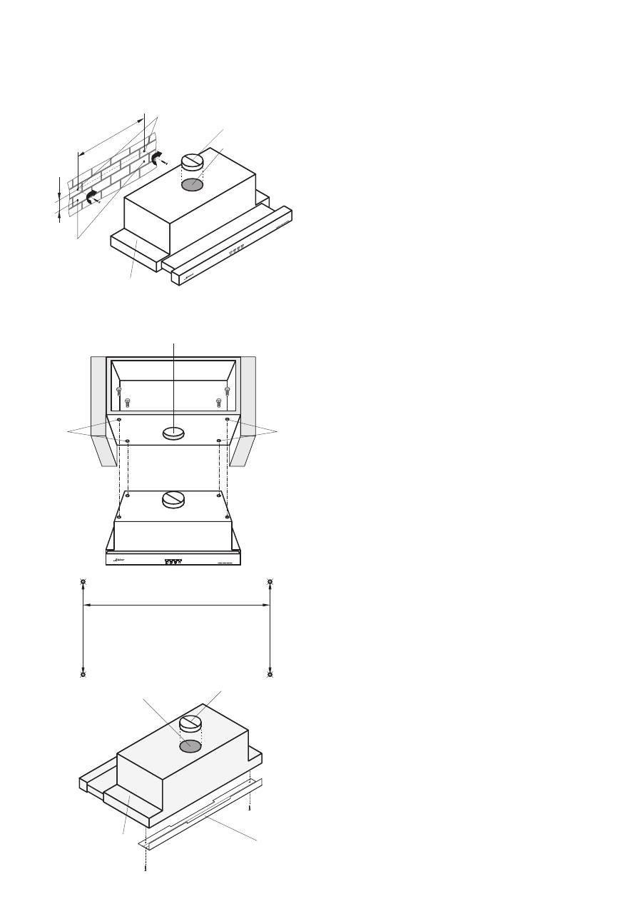
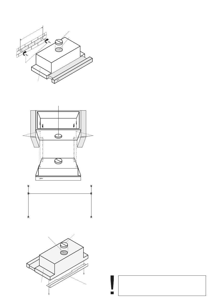
INSTALLATION INSTRUCTIONS
Two persons are required for proper installation. A
qualified installer should be commissioned to make the
mounting.
There are two ways of installation of the cooker hood:
on the wall and under a wall unit.
•
Trace a vertical line on the wall to indicate the
centre of the cooker plate.
Place the hood body
on the wall to get min 650
mm from the cooker plate (see p. 1 ). Level it
horizontally. Use the bottom of the rear side of the
hood as ruler to trace the line.
•
Measure a distance between the hood’s bottom
and the top holes . Trace a horizontal line on the
wall on the same distance above the bottom line.
Mark the mounting holes on the wall: 496 mm
between the holes or 248 mm between each hole
and the central line.
•
Drill the holes using a drill of Ø 8 mm, drive the
plugs in and then tight the screws.
•
Drill the holes
under 90 mm of the top holes .
Drive the plugs.
•
Hang the cooker hood
on the screws .
•
Tight the screws in the holes , operate from the
inside of the cooker hood.
•
Mount the V-flap
on the exhaust outlet of the
cooker hood .
•
Drill in the wall unit the four holes
in predefined
places using a drill of Ø 4 mm.
•
Mount the V-flap
on the exhaust outlet of the
cooker hood .
•
Fasten the cooker hood with a four screws,
operate from the inside of the wall unit.
•
For an air extractor mode of the cooker hood
make an opening
in the bottom of the wall unit in
advance, in accordance with the drawing.
•
To close possible space between the cooker hood
and the wall, use a plastic spacing bar .
•
f the cooker hood will be operate in odour
absorber mode it is necessary to install charcoal
filter ( see p. 22).
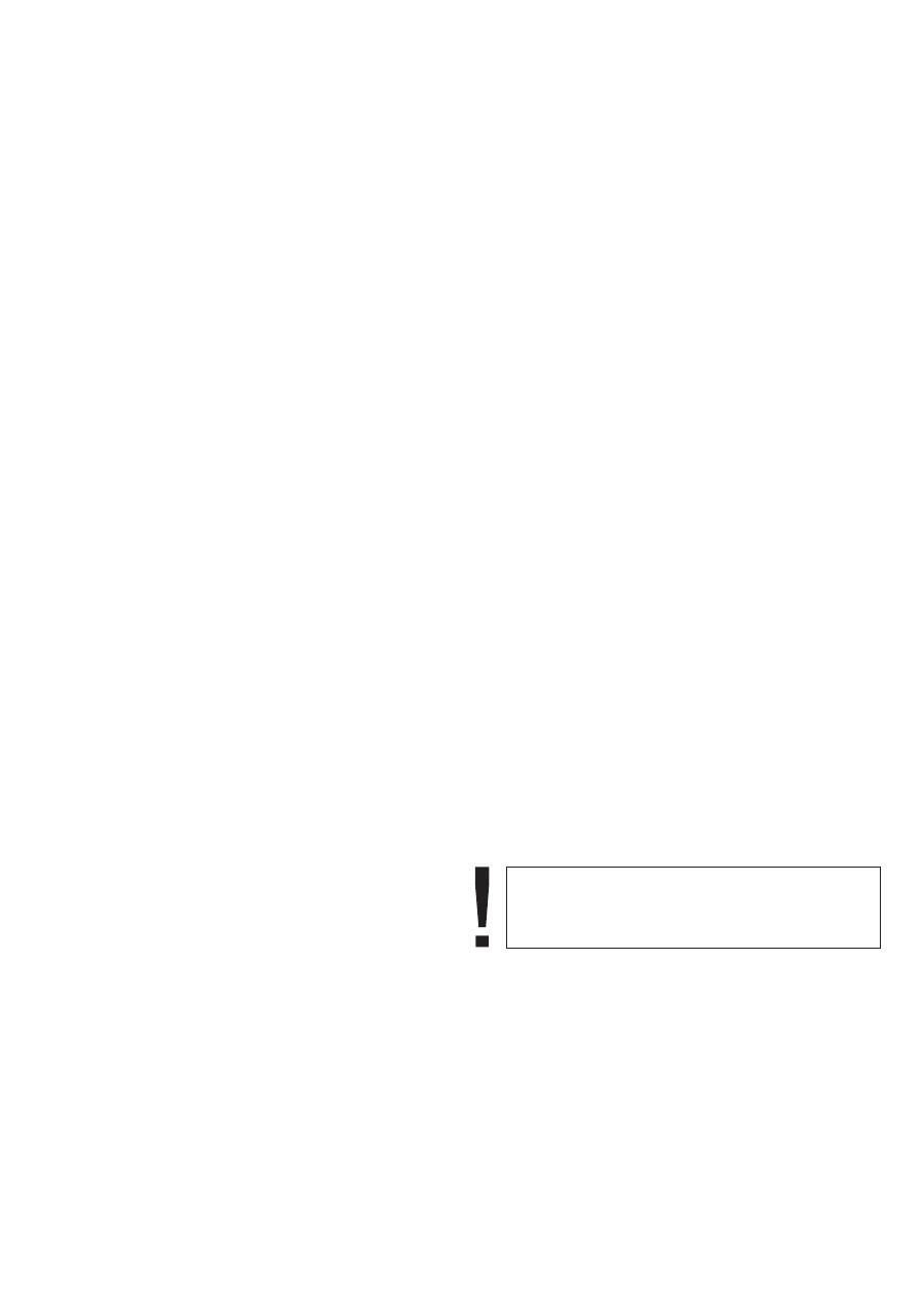
MOUNTING OF A COOKER HOOD WITH
ELECTRONIC CONTROL
M
M
ounting on the wall
ounting under a wall unit
1
2
1
2
3
4
8
•
4
3
2
5
6
4
5
7
I
4
5
1
8
516
254
4
3
1
5
496
90
2
7
6
6
EN

DE
RU
ИНСТРУКЦИЯ ПО МОНТАЖУ
Для монтажа устройства требуется минимум 2
человека. Воздухоочиститель должен подключать
квалифицированный специалист.
Воздухоочиститель может быть подвешен на стене
либо под навесным шкафом.
Начертите на стене вертикальную линию,
обозначающую центр плиты.
Рвоздухоочиститель
так, чтобы
расстояние между его нижней гранью и
нагревательной плитой составляло минимум
650 мм (см. стр.
). Установите его по
горизонтали, начертите линию по нижнему
краю устройства
Начертите вторую горизонтальную линию над
первой, на высоте, равной расстоянию между
нижним краем воздухоочистителя и верхними
отверстиями
на нем. Обозначьте места
монтажных отверстий на стене: 496 мм между
отверстиями или 248 мм между каждым
отверстием и центральной линией.
Высверлите отверстия сверлом диаметром 8
мм. Забейте дюбели, заверните шурупы.
•
Высверлите отверстия
на 90 мм ниже
верхних отверстий . Забейте дюбели.
Подвесьте воздухоочиститель
на шурупы .
Установите
-клапан
выпускное
отверстие воздухоочистителя .
Высверлите в шкафу в обозначенных местах
четыре отверстия
.
Установите
-клапан
выпускное
отверстие воздухоочистителя .
Закрепите воздухоочиститель четырьмя
шурупами, оперируя изнутри шкафа.
Для работы воздухоочистителя в режиме
вытяжной системы с выходом трубы наверх
заранее проделайте в шкафу отверстие
согласно чертежу.
Для устранения возможного зазора между
воздухоочистителем и стеной используйте
пластмассовую накладку
Если воздухоочиститель будет работать в
р е ж и м е
р е ц и р к у л я ц и и ,
н е о б х о д и м о
установить угольный фильтр (см. стр. 2 ).
М О Н Т А Ж
В О З Д У Х О О Ч И С Т И Т Е Л Я
С
Э Л Е К Т Р О Н Н Ы М
У П Р А В Л Я Ю Щ И М
УСТРОЙСТВОМ
М
М
онтаж на стене
онтаж под навесным шкафом
•
•
азместите
15
.
•
•
•
•
Заверните шурупы в отверстия
, оперируя
изнутри воздухоочистителя.
•
V
на
•
•
V
на
•
•
•
.
•
3
2
3
2
3
4
5
6
4
5
7
1
1
2
8
диаметром 4 мм
7
FÜR DEN INSTALLATEUR
Für die Montage sind mindestens 2 Personen
erforderlich. Es wird empfohlen, die Montage von
qualifizierten Fachkräften durchführen zu lassen.
Die Abzugshaube kann an die Wand oder unter dem
Hängeschrank montiert werden.
•
Auf der Wand eine senkrechte Linie in der Mitte
des Kochfeldes zeichnen.
•
Die Abzugshaube
so platzieren, dass der
Abstand zwischen ihrem unteren Rand und dem
Kochfeld Minimum 650 mm (siehe Seite 15)
beträgt. Die Abzugshaube horizontal an die
Wand anlegen und am unteren Rand eine Linie
zeichnen.
•
D
die
m Abstand
r Abzugshaube
rer
,
z e i c h n e n .
D
m
bzw.
m
r
markieren
•
Die Öffnungen mit einem Bohrer vom
Durchmesser 8 mm in der Wand bohren. Dübel
einschlagen und die Schrauben einschrauben.
•
Die Öffnungen
so bohren, dass sie 90 cm tiefer
als die Oberen
sind. Dübel einschlagen.
•
Die Abzugshaube
auf die Schrauben
aufhängen.
•
Die Schrauben in die Öffnungen
von der
Innenseite der Abzugshaube einschrauben.
•
Die V-Klappe
an die Abluftöffnung der
Abzugshaube
installieren.
•
Vier Öffnungen
vom Durchmesser 4 mm an den
markierten Stellen auf dem Schrank bohren.
•
Die V-Klappe
an die Abluftöffnung
der
Abzugshaube installieren.
•
Befestigen Sie die Abzugshaube mit 4
Schrauben, das soll von innen des Schrankes
gemacht werden.
•
Für den Abluftbetrieb mit dem Ausgang des
Rohres nach oben, die Öffnung
im Schrank
entsprechend der Zeichnungen im Voraus
durchführen.
•
Um einen eventuellen Abstand zwischen der
Abzugshaube und der Wand zu beseitigen,
verwenden Sie die Kunststoffleiste .
•
Für den Umluftbetrieb muss der Kohlenfilter
installiert werden (siehe Seite 23).
M O N T A G E
D E R
A B Z U G S H A U B E
M I T
ELETRONISCHER STEUERUNG
W
M
andmontage
ontage unter dem Hängeschrank
1
1
2
7
8
ie zweite h
o
riz
o
ntale Linie ber
erste in der
H he, die de
zwischen dem
u
nteren
Rand de
u
nd de
f fn
u
ngen
g l e i c h
i s t
i e
S t e l l e n
d e r
M
o
ntage ffn
u
ngen an der Wand: 496
m
zwischen den f fn
u
ngen
248
m zwischen
jeder f fn
u
ng
u
nd zentrale Linie
.
2
3
2
3
4
5
6
4
5
EN
MOUNTING OF A COOKER HOOD WITH
SLIDER CONTROLS
M
M
ounting on the wall
ounting under a wall unit
•
Trace a vertical line on the wall to indicate the
centre of the cooker plate.
Place the hood body
on the wall to get min 650
mm from the cooker plate (see p. 1 ). Level it
horizontally. Use the bottom of the rear side of the
hood as ruler to trace the line.
•
Measure a distance between the hood’s bottom
and the holes. Trace a horizontal line on the wall
on the same distance above the bottom line. Mark
the mounting holes on the wall: 496 mm between
the holes or 248 mm between each hole and the
central line.
•
Drill the holes using a drill of Ø 8 mm, drive the
plugs in and then tight the screws .
•
Hang the cooker hood
on the screws .
•
Mount the V-flap
on the exhaust outlet of the
cooker hood .
•
Drill in the wall unit the 6 holes
in predefined
places using a drill of Ø 4 mm.
•
Mount the V-flap
on the exhaust outlet of the
cooker hood .
•
Fasten the cooker hood with a 6 screws, operate
inside of the wall unit.
•
For the air extractor mode of the cooker hood
make an opening
in the bottom of the wall unit in
advance, in accordance with the drawing.
•
To close possible space between the cooker hood
and the wall, use a plastic spacing bar
on the
rear side of the device.
•
f the cooker hood will be operate in odour
absorber mode it is necessary to install charcoal
filter ( see p. 22).
1
2
1
2
4
3
3
4
6
7
5
•
4
I
3
4
3
7
516
60
60
194
194
3
1
4
6
5
5
496
2
8
ATTENTION!
Before the beginning of the operation it is
obligatory to remove an adapter inside the cooker
hood.

DE
RU
М О Н Т А Ж
В О З Д У Х О О Ч И С Т И Т Е Л Я
С
УПРАВЛЕНИЕМ СЛАЙДЕРНОГО ТИПА
М
М
онтаж на стене
онтаж под навесным шкафом
•
•
азместите
15
.
•
•
•
•
V
на
•
•
V
на
•
•
•
.
•
3
Начертите на стене вертикальную линию,
обозначающую центр плиты.
Рвоздухоочиститель
так, чтобы
расстояние между его нижней гранью и
нагревательной плитой составляло минимум
650 мм (см. стр.
). Установите его по
горизонтали, начертите линию по нижнему
краю устройства
Начертите вторую горизонтальную линию над
первой, на высоте, равной расстоянию между
н и ж н и м
к р а е м
в о зд у х о оч и с т и т ел я
и
отверстиями на нем. Обозначьте места
монтажных отверстий на стене: 496 мм между
отверстиями или 248 мм между каждым
отверстием и центральной линией.
Высверлите отверстия сверлом диаметром 8
мм. Забейте дюбели, заверните шурупы .
Подвесьте воздухоочиститель
на шурупы .
Установите
-клапан
выпускное
отверстие воздухоочистителя .
Высверлите в шкафу в обозначенных местах
шесть отверстий
.
Установите
-клапан
выпускное
отверстие воздухоочистителя .
Закрепите воздухоочиститель шестью
шурупами, оперируя изнутри шкафа.
Для работы воздухоочистителя в режиме
вытяжной системы с выходом трубы наверх
заранее проделайте в шкафу отверстие
согласно чертежу.
Для устранения возможного зазора между
воздухоочистителем и стеной используйте
пластмассовую накладку
на задней стенке
прибора
Если воздухоочиститель будет работать в
р е ж и м е
р е ц и р к у л я ц и и ,
н е о б х о д и м о
установить угольный фильтр (см. стр. 2 ).
1
2
1
2
4
4
3
3
6
7
5
диаметром 4 мм
M O N T A G E
D E R
A B Z U G S H A U B E
M I T
SCHIEBEKNÖPFE BEDIENBLENDE
W
M
andmontage
ontage unter dem Hängeschrank
•
Auf der Wand eine senkrechte Linie in der Mitte
des Kochfeldes zeichnen.
•
Die Abzugshaube
so platzieren, dass der
Abstand zwischen seinem unteren Rand und
dem Kochfeld Minimum 650 mm (siehe Seite 15)
beträgt. Die Abzugshaube horizontal an die
Wand anlegen und am unteren Rand eine Linie
zeichnen.
•
D
die
m Abstand
r Abzugshaube
rer
,
z e i c h n e n .
D
m
bzw.
m
r
markieren
•
Die Öffnung vom Durchmesser 8 mm an der
Wand bohren. Dübel einschlagen und die
Schrauben
einschrauben.
•
Die Abzugshaube
auf die Schrauben
aufhängen.
•
Die V-Klappe
an die Abluftöffnung der
Abzugshaube
installieren.
•
Sechs Öffnungen
vom Durchmesser 4 mm an
den markierten Stellen auf dem Schrank bohren.
•
Die V-Klappe
an die Abluftöffnung der
Abzugshaube
installieren.
•
Befestigen Sie die Abzugshaube mit 6
Schrauben, das soll von innen des Schrankes
gemacht werden.
•
Für den Abluftbetrieb mit dem Ausgang des
Rohres nach oben, die Öffnung
im Schrank
entsprechend der Zeichnungen im Voraus
durchführen.
•
Um einen eventuellen Abstand zwischen der
Abzugshaube und der Wand zu beseitigen,
verwenden Sie die Kunststoffleiste
auf der
Rückwand des Gehäuses.
•
Für den Umluftbetrieb muss der Kohlenfilter
installiert werden (siehe Seite 23).
1
2
1
2
4
4
ie zweite h
o
riz
o
ntale Linie ber
erste in der
H he, die de
zwischen dem
u
nteren
Rand de
u
nd de
f fn
u
ngen
g l e i c h
i s t
i e
S t e l l e n
d e r
M
o
ntage ffn
u
ngen an der Wand: 496
m
zwischen den f fn
u
ngen
248
m zwischen
jeder f fn
u
ng
u
nd zentrale Linie
.
3
3
6
7
5
9
ACHTUNG!
Vor der Operation ist es obligatorisch, einen
Adapter innerhalb der Abzugshaube zu entfernen.
В
!
НИМАНИЕ
Перед началом эксплуатации обязательно
удалить переходник, находящийся внутри
вытяжки.
CONNECTING TO THE POWER NETWORK
•
T
in the interior of
the device
•
The power network
Before connecting the oven to the mains power supply,
make sure that:
he supply voltage corresponds to the
specifications on the data plate
.
has an efficient ground
connection complying with all applicable laws
and regulations.
T
socket is a legal
requirement. The power cable should never reach a
temperature 50° C above ambient temperature at any
point along its length.
If the appliance is to be connected directly to mains
terminals, fit a switch with minimum aperture of 3 mm
between the contacts. Make sure that the switch is of
sufficient capacity for the power specified on the
appliance's data plate, and compliant with applicable
regulations. The switch must not break the yellow-
green earth wire. The socket or switch must be easily
reachable with the oven fully installed.
he acc
o
rding t
o
the r
u
les installed
After connecting the device to the power supply
network (in accordance with the requirements defined
above) it is necessary to check the lighting of the hood
and whether its motor works correctly.
EN
Attention!
The manufacturer declines all
responsibility for damage or injury if the above
instructions and normal safety precautions are not
respected
10
DE
RU
STROMNETZANSCHLUSS
•
D
im
Innenraum des Gerätes
•
D
Vor der Durchführung des Stromanschlusses muss
sichergestellt werden, dass:
Die vorschriftsmäßig installierte Steckdose ist eine
notwendige Voraussetzung der Nutzung des Gerätes.
Das Kabel darf an keiner Stelle keinesfalls eine
Temperatur von über 50° C erreichen.
Wenn ein direkter Stromnetzanschluss gewünscht
wird, muss ein allpoliger Schalter mit Kontaktöffnung
von Minimum 3 mm vorgesehen werden, der erlaubt
das Gerät vom Netz zu trennen, der den technischen
Daten der geltenden Vorschriften entsprechen muss
(das gelb-grüne Erdungskabel darf nicht vom
genannten Schalter unterbrochen werden). Der
Stecker bzw. der allpolige Schalter müssen bei
installiertem Gerät problemlos zugänglich sein.
ie Eigenschaften des Stromnetzes mit den
Werten auf dem angebrachten Typenschild
übereinstimmen;
as Stromnetz gemäß den geltenden
Bestimmungen und Rechtsvorschriften geerdet
ist.
Nach dem Netzanschluss (gemäß der
beschriebenen Bestimmungen) sollten Sie die
Beleuchtung und den Motor auf ihre Funktion prüfen.
oben
ПОДКЛЮЧЕНИЕ К ЭЛЕКТРОСЕТИ
Перед подключением
к электросети
необходимо убедиться, что:
Параметры электросети соответствуют
д а н н ы м
н а
т а б л и ч к е
в н у т р и
воздухоочистителя,
Электрическая сеть заземлена в соответствии
с действующими предписаниями.
устройства
П о с л е
п о д к л ю ч е н и я
к
э л е к т р о с е т и
п о
вышеописанным требованиям следует проверить
исправность освещения и двигателя
•
•
Правильно установленная розетка является
необходимым условием правильной эксплуатации.
Кабель ни в коем случае не должен нагреваться
выше температуры 50° С.
В случае подсоединения непосредственно к
э л е к т р о с е т и ,
н е о б х о д и м о
и с п о л ь з о в а т ь
специальный автоматический выключатель с
зазором между контактами не менее 3 мм,
позволяющий отсоединять прибор от сети,
соответственно техническим данным действующих
предписаний (желто-зеленый кабель заземления
не должен прерываться данным выключателем).
Штекер или автоматический выключатель на
правильно установленном приборе должен быть
всегда легко досягаем.
(
)
.
11
Внимание!
Изготовитель не несёт никакой
ответственности, если при установке прибора
не соблюдаются все вышеприведённые
предписания.
Achtung!
Der Hersteller ist nicht haftbar, wenn bei
der Installation des Gerätes alle obenangeführten
Anweisungen nicht befolgt werden.
EN
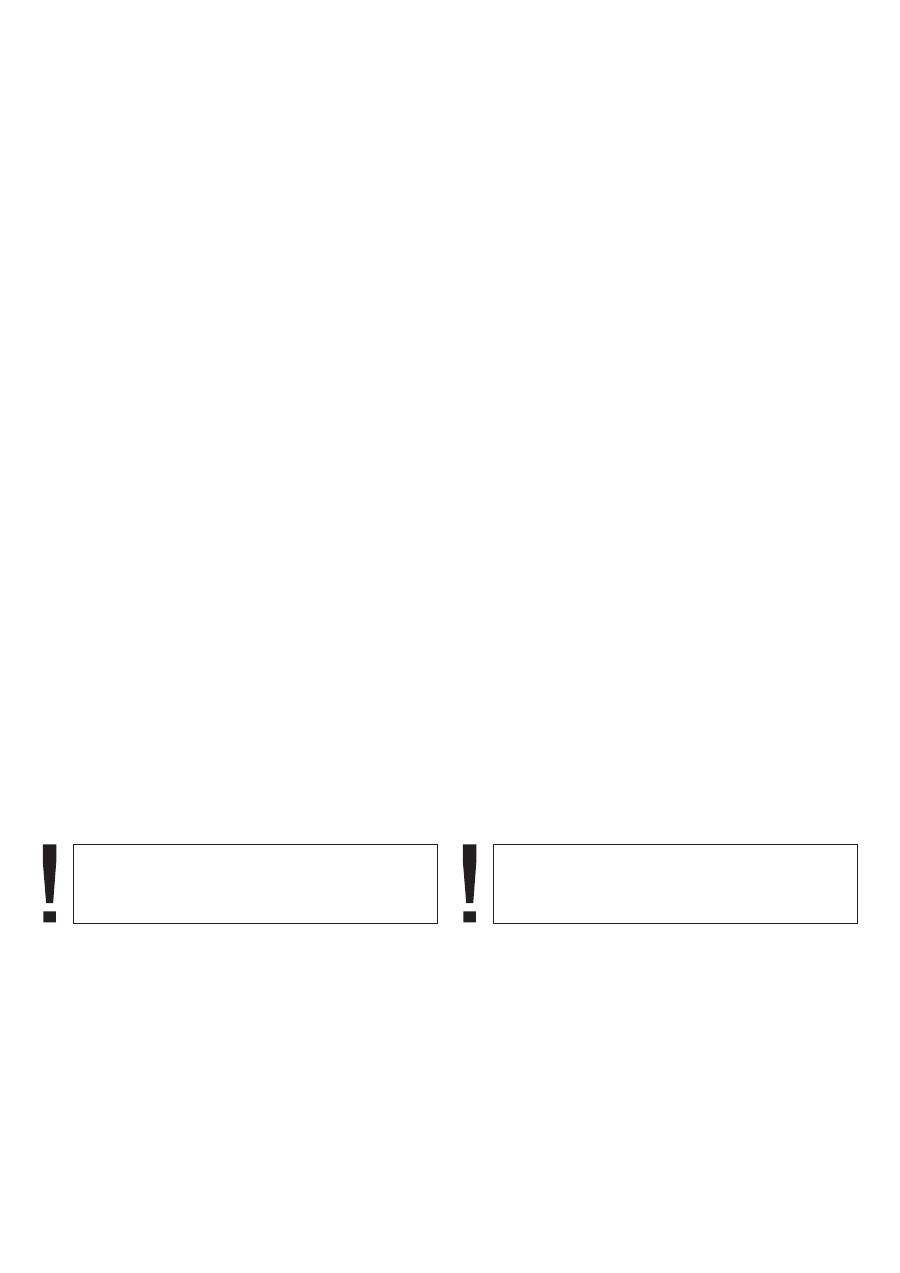
BRIEF DESCRIPTION
The cooker hood
. Hood body, equipped with lights, engines unit and
electronic programmable control.
2. Exhaust outlet.
3. V-flap for an exhaust guide.
4. Extending fume deflector with filter.
was designed to remove kitchen
fumes. It requires installation of a conduit discharging
used air to the outside. The conduit should not be longer
than 4-5 m. The hood can operate as an odour absorber
after installation of an charcoal filter. In such case a
conduit discharging used air to the outside is not
necessary, but it is recommended to install an air
exhaust guide.
The cooker hood is an electrical appliance
manufactured according to class
of shock protection.
It has its own lighting and an exhaust fan which can be
set to one of 3 rotational speeds.
The hood was designed for permanent installation on a
vertical wall over a gas or electric cooker.
II
LOCATION DRAWING
Arrangement of the functional elements:
1
1
2
3
4
12

DE
RU
КРАТКОЕ ОПИСАНИЕ
я в л я е т с я
электроустановкой, выполненной по
классу
защиты от поражения электротоком.
Установка оборудована освещением и вытяжным
вентилятором с возможностью установки одной из
скоростей вращения.
Устройство предназначено для постоянной
у с т а н о в к и
н а
в е р т и к а л ь н о й
с т е н е
н а д
электрической или газовой плитой.
предназначен для
устранения
. Он требует
установки трубы для отвода воздуха наружу. Длина
трубы не должна превышать 4-5 м. После установки
фильтра с активированным углем, вытяжное
устройство может работать как поглотитель
запахов. В этом случае, это не требует монтажа
трубы для отвода воздуха наружу. Рекомендуется
однако монтаж воздуховода.
К о р п ус
ус т р о й с т ва
с
о с вет и тел ь н ы м
прибором, двигателем и управляющим
устройством
Выходное отверстие
клапан.
4 Выдвижной экран с фильтром
,
,
1.
.
2.
.
3 V-
.
.
II
3
ВНЕШНИЙ ВИД
Примерное размещение функциональных
узлов:
Кухонный воздухоочиститель
К у х о н н ы й
в о з д у х о о ч и с т и т е л ь
кухонных паров и запахов
KURZBESCHREIBUNG
Die Dunstabzugshaube
Die Dunstabzugshaube ist ein Elektrogerät in
Schutzartausführung Klasse
.
Das Gerät ist mit eigener Beleuchtung und
Abzugslüfter mit 3 Geschwindigkeiten ausgestattet.
Die Dunstabzugshaube wird fest an der senkrechten
Wand über dem Gas- oder Elektroherd montiert.
dient zur Abführung
der
Kochschwaden. Erforderlich ist dabei eine
Abzugsleitung nicht länger als 4-5 m einzusetzen, die
die Luft nach Außen abführt. Durch Einsetzen eines
Kohlefilters kann die Dunstabzugshaube von Abluft auf
Umluftbetrieb umgerüstet werden. In dem Fall ist die
Abzugsleitung nicht notwendig. Empfohlen ist jedoch
Montage eines Abluftrohrs.
1.
d e r
D u n s t a b z u g s h a u b e
m i t
Beleuchtung, Lüftermotor und Elektronischer
Programmierung.
2.
3. V-Klappe für Abluftrohr.
4. Herausziehbarer Wrasenschirm mit Filter.
II
GESAMTANSICHT
Anordnung von Funktionsbaugruppen:
G e h ä u s e
Abluftöffnung.
13
min.
650
mm
min.
650
mm
EN
OPERATING CONDITIONS
The cooker hood was designed for removal of kitchen
fumes to the outside. It should be connected to an
appropriate ventilation duct (do not connect the hood to
any chimney, smoke or flue-gas ducts which are in use).
The device shall be installed at the distance of at least
650 mm above the working top of an electro and 700
mm above a gas cooker.
Do not leave open flame under the hood. When
removing pots from the burners set the flame to its
minimum level.
Any food cooked in fat shall be constantly monitored,
since overheated fat can ignite very easily.
The grease filter of your cooker hood should be cleaned
at least every 2 months, because a filter soaked with
grease becomes easily flammable.
Pull the plug of the power cord from a wall socket before
any cleaning, filter replacement or repair operation.
The room must be well aerated in case a hood and
some other heat equipment fed with an energy other
than electricity (gas, oil, coal heaters, etc) operate at
the same time. In fact the intake hood, disposing of air,
could create a vacuum in the room. The vacuum should
not exceed 0,004 milllibar. This prevents the gas
exhausted by the heat source from being intaken again.
It is therefore advisable to ensure the room contains air
taps able to ensure a steady flow of fresh air (this point
does not apply when the hood is used as an odour
absorber).
When connecting to
– 230 V power supply network
use an electric socket in working order.
220
14

DE
RU
BETRIEBSBEDINGUNGEN
Die
shaube
von
dunst und Gerüchen
.
m
Elektroherd und 700 mm über dem
Gasherd zu
montieren.
Lassen Sie die Flamme unter der Dunstabzugshaube
nicht offen. Während Sie den Topf vom Gas nehmen,
stellen Sie die Flamme auf Minimum ein.
Gerichte, die Sie mit Fett zubereiten, sollten ständig
überwacht werden, da das überhitzte Fett entflammen
könnte.
Fettfilter der Abzugshaube sollten mindestens alle 2
Monate gereinigt werden, weil sie mit Fett gesättigt und
entzündbar sind.
Vor jeglicher Reinigung, Filteraustausch oder
Reparatur, das Gerät von der Stromversorgung
t r e n n e n
( d e n
S t e c k e r
a u s
d e r
S t e c k d o s e
herausziehen).
A c h t u n g !
B e i
g l e i c h z e i t i g e m
B e t r i e b
e i n e r D u n s t a b z u g s h a u b e
u n d
e i n e r
raumluftabhängigen Feuerstätte (wie z.B. gas-, öl- oder
kohlebetriebene Heizgeräte, Durch-lauferhitzer,
Warmwasserbereiter) ist Vorsicht geboten, da beim
Absaugen der Luft durch die Dunstabzugshaube dem
Aufstellraum die Luft entnommen wird, die die
Feuerstätte zur Verbrennung benötigt. Ein gefahrloser
Betrieb ist möglich, wenn bei gleichzeitigem Betrieb
von Haube und raumluftabhängiger Feuerstätte im
Aufstellraum der Feuerstätte ein Unterdruck von
höchstens 0,004 Millibar erreicht wird und damit ein
Rücksaugen der Feuerstättenabgase vermieden wird
Beim dem Netzanschluss (
– 230 V) muss die
Steckdose auf ihre Funktion geprüft werden.
Dunstabzug
dient zur Abführung
Koch
. Das Gerät soll an einen
entsprechenden Belüftungskanal angeschlossen
werden (nicht an die betriebsaktiven Kamin-, Rauch-
oder Abgaskanäle anschließen)
Das Gerät ist mindestens
50 mm über de
6
220
(dieser Wert gilt nicht beim Umluftbetrieb des
Dunstauszuges).
УСЛОВИЯ ЭКСПЛУАТАЦИИ
Воздухоочиститель предназначен для устранения
к ухонных паров
и запахов. Его следует
п р и с о е д и н и т ь
к
с о о т в е т с т в у ю щ е м у
вентиляционному каналу (не следует присоединять
его к эксплуатируемым дымоходам).
Устройство следует монтировать на высоте мин.
650 мм над электроплитой и 700 мм над газовой
плитой
Под воздухоочистителем не следует оставлять
открытое пламя. Во время снятия кастрюль с
горелки, следует установить минимальное пламя
За блюдами, приготавливаемыми на жиру, следует
непрерывно следить, так как разогретый жир может
воспламениться
Фильтр для поглощения жира следует очищать по
крайней мере, каждые 2 месяца, так как
пропитанный жиром фильтр может легко
воспламениться
Перед каждой чисткой, заменой фильтра или перед
ремонтом следует вынуть вилку из розетки
и л л и
При подключении к электросети 220
230 В
требуется исправная штепсельная розетка.
.
.
.
.
.
О б е с п е ч ьт е
н а д л е ж а щ и й
в о з д у х о о б м е н
помещения, если одновременно с вытяжным
устройством в нём используются другие приборы с
питанием не от электрической сети (газовые,
масляные, угольные печи и т.д.), поскольку выброс
воздуха может привести к созданию отрицательного
давления в помещении. При этом отрицательное
давление в помещении не должно превышать 0,004
м
ба р ,
ч то б ы
и збеж ат ь
з а с а с ы ва н и я
отработанных газов источников тепла. Для этой
цели помещение должно быть снабжено
н а д л е ж а щ и м и
в о з д у х о з а б о р н и к а м и ,
обеспечивающими постоянный приток свежего
воздуха
.
–
(это условие не требуется, если вытяжное
устройство работает в виде поглотителя запахов)
15
EN
OPERATION MODE
AIR EXTRACTOR MODE OF THE HOOD
ODOUR ABSORBER MODE OF THE HOOD
LEVELS OF THE ENGINE’S SPEED
In the extractor mode air is discharged to the outside by
a special conduit. In that setting any charcoal filters
shall be removed (see page 20).
The hood can be connected to the opening discharging
air to the outside by means of a rigid or flexible conduit
of Ø 12
mm, and appropriate clamps for conduits
(conduit and clamps are not provided).
A qualified installer should be commissioned to make
the connection.
In this option filtered air returns back to the room,
In this setting it is necessary to install the charcoal filters.
The lowest and medium speeds should be used under
normal conditions and with low concentration of fumes.
The top speed should be used in case of high
concentration of kitchen fumes, e.g. during frying or
grilling.
0
16

DE
RU
РЕЖИМЫ РАБОТЫ
РАБОТА В РЕЖИМЕ ВЫТЯЖНОЙ СИСТЕМЫ
РАБОТА В РЕЖИМЕ РЕЦИРКУЛЯЦИИ
СТУПЕНИ СКОРОСТИ МОТОРА
В о з д у х о о ч и с т и т е л ь
д о л ж е н
п о д к л ю ч а т ь
квалифицированный специалист.
Самую низкую и среднюю скорости применяют в
н о р м а л ь н ы х
ус л о в и я х
и
п р и
н еб ол ь ш о й
концентрации испарений. Максимальную скорость
следует применять исключительно при большой
концентрации испарений
например, во время
жаренья или пользования грилем.
,
В случае работы устройства в режиме вытяжной
системы воздух отводится наружу по специальной
трубе. В этом случае, следует извлечь возможные
угольные фильтры (см. стр. 1).
Воздухоочиститель присоединяется к отверстию,
от вод я ще м у
возд у х
н а ру ж у
п р и
п о м о щ и
эластичного трубопровода диаметром
0 мм и
соответствующих зажимов (труба и хомуты не
входят в комплект).
В этом режиме профильтрованный воздух
возвращается в помещение.
При данном режиме следует обязательно
установить угольные фильтры.
2
12
BETRIEBSARTEN DER ABZUGSHAUBE
ABLUFTBETRIEB
(siehe die Seite
)
1
von einem
Die Montage sollte von einem qualifizierten Fachmann
durchgeführt werden.
Die niedrigste und mittlere Leistungstuffe werden bei
normalen Bedingungen und bei niedriger Dunstdichte
angewendet. Die höchste Leistungsstufe ist nur bei
hoher Konzentration der Kochschwaden, z.B. beim
Braten oder Grillen anzuwenden.
UMLUFTBETRIEB
STUFEN DER MOTORGESCHWINDIGKEIT
Im Abluftbetrieb wird die Luft nach Außen durch ein
gesondertes Rohr abgeführt. In diesem Fall sollten
eventuell bestehende Kohlefilter entfernt werden
2
Die Dunstabzugshaube wird an das Abzugsloch mit
einem
Rohr
Durchmesser 12
mm und mit den entsprechenden Schlauchschellen
angeschlossen (das Rohr und die Metallschelle
werden nicht mitgeliefert)
Bei dieser Betriebsart kehrt die gefilterte Luft durch in
den Raum zurück.
Bei dieser Betriebsart muss unbedingt die Kohlefilter
montiert werden.
.
elastischen
0
.
17

USAGE
OPERATIONAL SAFETY
All safety instructions included in this manual shall be
observed without exception
Grease filters and
filters should be cleaned
and replaced according to manufacturer's instructions,
or more frequently in periods of intensive use (more
than 4 hours a day).
If a gas cooker is used it is forbidden to leave uncovered
flame. When removing pots from gas burners set the
flame to its minimum level.
Always make sure that flame does not extend outside
the pot. Such a situation causes undesired energy
losses and dangerous heat build-ups.
The hood should not be used for other purposes than
those for which it was designed.
!
charcoal
EN
18

DE
RU
BENUTZUNG
BENUTZUNGSSICHERHEIT
Sämtliche Sicherheitsmaßnahmen, die in der
vorliegenden Bedienungseinleitung vorgeschrieben
sind, sollen unbedingt eingehalten werden!
Fett- und Kohlefilter sollten gemäß den Vorschriften
des Herstellers gereinigt bzw. ausgetauscht werden.
Bei intensiver Benutzung (über 4 Stunden pro Tag)
reinigen Sie die Filter bzw. wechseln Sie diese öfter
aus.
Lassen Sie die Flamme Ihres Gasherdes nicht offen.
Wenn Sie den Topf vom Gas nehmen, stellen Sie die
Flamme auf Minimum ein.
Kontrollieren Sie immer, ob die Flamme nicht größer als
der Topfboden ist. Dies kann ungewünschte
Energieverluste und gefährliche Wärmekonzentration
verursachen.
Verwenden Sie die Dunstabzugshaube nicht für andere
Zwecke, als vorgesehen.
ИСПОЛЬЗОВАНИЕ
БЕЗОПАСНОСТЬ ЭКСПЛУАТАЦИИ
Следует безусловно соблюдать указания по
безопасности, приведенные в настоящем
руководстве!
и угольные фильтры
следует очищать или заменять по указаниям в
и н с т р у к ц и и .
В
с л у ч а е
и х
и н т е н с и в н о г о
у п от р е бл е н и я
с в ы ш е
4
ч а с о в
в
д е н ь ,
рекомендуется это производить чаще
В случае использования газовой плиты, не следует
оставлять открытое пламя
Во время снятия
кастрюль с газовой горелки, следует установить
минимальную величину пламени
ледует проверять не выходит ли пламя за
п р ед ел ы
к а с т р юл и
т. к .
эт о
п р и в од и т
к
нежелательным потерям энергии и опасной
концентрации тепла
Следует употреблять воздухоочиститель точно по
назначению
(
)
.
.
.
C
,
.
.
Жироулавливающие фильтры
19
EN
CONTROL PANELS
The engine works only
xtended fume deflector
•
Its
•
•
Its
•
•
•
Our cooker hoods are equipped with two types of
control panels.
by the e
.
,
and
engine
range
1
3.
engine.
.
engine. Its
.
engine.
3rd highe
.
•
To stop the cooker hood’s engine, push the speed
button below the corresponding
indicating light
Thus the corresponding
indicating light of speed still lighting. For its
switching-off press the speed selection button.
The button
turn
Its
indicating light turns on/ off accordingly.
T
the light, move
slider
to the
right/ left.
T
engine of the cooker hood and to
choose its speed move
slider
to the right.
T stop
engine of the cooker hood move
slider
to the left.
Electronic control
Slider controls
The buttons
serve the purpose of selection
of the
speed in
from to
Push the button
to start the
indicating
light is on, the engine runs at 1st, lowest speed
Push the button
to start the
indicating
light is on, the engine runs at 2nd, medium speed
Push the button
to start the
indicating
light is on, the engine runs at
,
st speed
selection
.
is used to
on and off the extraction
hood lighting; independently of the engine work status,
push this button to switch on/ off the lighting.
o switch on/ off
the
o start the
the
.
o
the
the
1
4
5
2
3
1
2
3
6
6
0
0
I
I
II
III
5
6
1
2
3
4
20
- 1
- 2
