Interlogix TVD-TIR6: инструкция
Раздел: Устройства видеонаблюдения
Тип:
Инструкция к Interlogix TVD-TIR6

TruVision IR Dome
Camera
EN Pocket Guide
DE Kurzanleitung
ES Guía de bolsillo
FR Guide de poche
IT Guida rapida
NL Beknopte handleiding
PL Kieszonkowy przewodnik
PT Guia Rápido
RU Карманное руководство
TR Cep Kılavuzu
P/N 1076545B • ISS 05JUN12


Contents / Inhalt / Contenido /
Table des matières / Indice /
Inhoudsopgave / Spis treści /
Índice / Содержание / İçindekiler
Figures ....................................................... 3
EN ............................................................. 10
DE ............................................................. 15
ES .............................................................. 21
FR .............................................................. 27
IT ............................................................... 33
NL .............................................................. 39
PL .............................................................. 45
PT .............................................................. 51
RU ............................................................. 57
TR .............................................................. 64
1

Legal / Rechtliche Angaben / Información
legal / Informations légales / Note legali /
Juridisch / Informacje prawne / Informação
legal / Нормативно-правовые аспекты /
Yasal .......................................................... 69
2
Figures
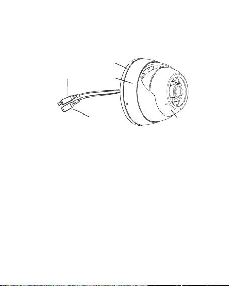
EN Figure 1: Parts of the camera
A. Video cable; B. Power cable; C. Mounting
bracket; D. Shroud; E. Camera
DE Abbildung 1: Teile der Kamera
A. Videokabel; B. Stromkabel;
C. Montagehalterung; D. Schutzabdeckung;
E. Kamera
ES Figura 1: Partes de la cámara
A. Cable de vídeo; B. Cable de
alimentación; C. Soporte de montaje;
D. Protección; E. Cámara
FR Figure 1 : Éléments de la caméra
A. Câble vidéo ; B. Câble d'alimentation ;
3

C. Support de monta
4
g
e; D.Capo
t
; E. Camér
a
IT Figura 1: parti della telecamera
A. Cavo video; B. Cavo di alimentazione; C.
Supporto di montaggio; D. Rivestimento; E.
Telecamera
NL Afbeelding 1: Onderdelen van de camera
A. Videokabel; B. Voedingskabel;
C. Monta
g
esteun; D. Mantel; E. Camera
PL Rysunek 1: elementy kamery
A. Przewód wideo; B. Kabel zasilania;
C. Uchw
y
t mocu
ją
c
y
; D. Osłona; E. Kamera
PT Figura 1: Componentes da câmara
A. Cabo de vídeo; B. Cabo de alimentação;
C. Suporte de montagem; D. Cobertura; E.
Câmara
RU Рис. 1. Детали камеры
A. Видеокабель; B. Кабель питания;
C. Монтажный кронштейн; D. Кожух;
E. Камера
TR Şekil 1: Kameranın parçaları
A. Video kablosu; B. Güç kablosu;
C. Monta
j
aparatı; D. Örtü; E. Kamera
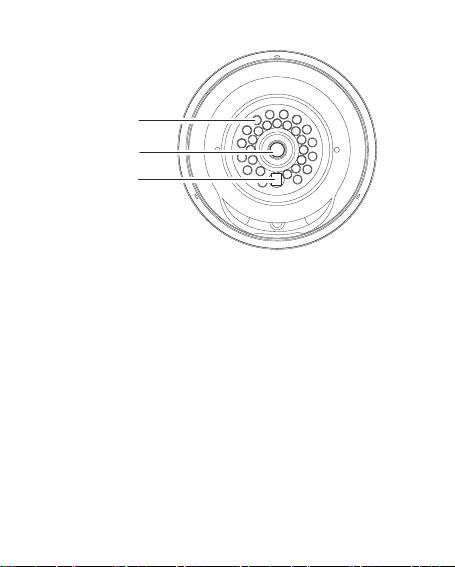
EN Figure 2: Camera front
A. LED IR lights; B. Lens; C. Light sensor
DE Abbildung 2: Vorderseite der Kamera
A. LED-IR-Leuchten; B. Objektiv;
C. Lichtsensor
ES Figura 2: Parte delantera de la cámara
A. Luces LED IR; B. Lente; C. Sensor de luz
FR Figure 2 : Avant de la caméra
A. Témoins lumineux LED IR ;
B. Objectif ; C. Capteur de luminosité
5

IT Figura 2: parte anteriore della
telecamera
A. IR LED; B. Obiettivo; C. Sensore luce
NL Afbeelding 2: Voorkant camera
A. Infrarood LED's; B. Objectief;
C. Lichtsensor
PL Rysunek 2: przód kamery
A. Diody podczerwieni; B. Obiektyw;
C. Czujnik światła
PT Figura 2: Parte da frente da câmara
A. Luzes LED IV; B. Lente; C. Sensor
de luz
RU Рис. 2. Камера (вид спереди)
A. Инфракрасные светодиоды;
B. Объектив; C. Оптический датчик
TR Şekil 2: Kameranın önü
A. LED IR ışıklar; B. Lens; C. Işık sensörü
6
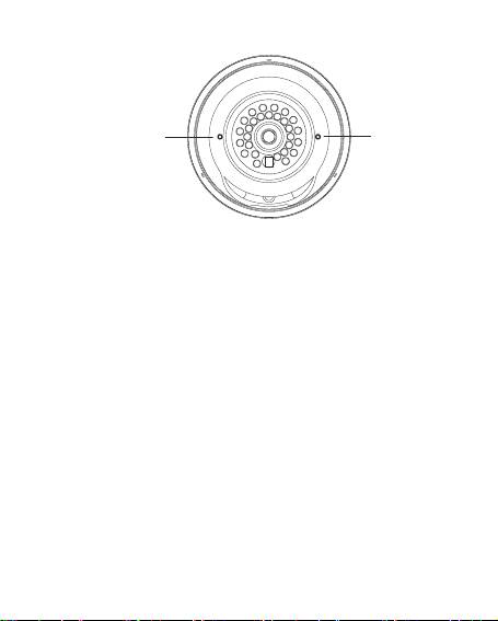
EN Figure 3: Camera zoom and focus
adjustment
A. Focus; B. Zoom
Note: Zoom and focus are only available
on the TVD-TIR6-MR(-P) and TVD-TIR6-
HR(-P) models.
DE Abbildung 3: Zoom- und
Fokuseinstellung der Kamera
A. Fokus; B. Zoom
Hinweis: Zoom und Fokus sind nur bei
den Modellen TVD-TIR6-MR(-P) und
TVD-TIR6-HR(-P) verfügbar.
7

ES Figura 3: Ajuste del zoom y del
enfoque de la cámara
A. Enfoque; B. Zoom
Nota: el enfoque y el zoom solo están
disponibles en los modelos
TVD-TIR6-MR(-P) y TVD-TIR6-HR(-P).
FR Figure 3 : Réglage du zoom et de la
mise au point de la caméra
A. Mise au point ; B. Zoom
Remarque : Le zoom et la mise au point
ne sont disponibles que sur les modèles
TVD-TIR6-MR(-P) et TVD-TIR6-HR(-P).
IT Figura 3: regolazione dello zoom e
della messa a fuoco della telecamera
A. Messa a fuoco; B. Zoom
Nota: la messa a fuoco e lo zoom sono
disponibili solo sui modelli
TVD-TIR6-MR(-P) e TVD-TIR6-HR(-P).
NL Afbeelding 3: Camerzoomfunctie en
scherpstelling
A. Focus; B. Zoom
Opmerking: Zoomen en scherpstellen is
alleen mogelijk op de modellen
TVD-TIR6-MR(-P) en TVD-TIR6-HR(-P).
8

PL Rysunek 3: regulacja powiększenia i
ostrości kamery
A. Ostrość; B. Powiększenie
Uwaga: regulacja powiększenia i ostrości
dostępna jest tylko w modelach
TVD-TIR6-MR(-P) i TVD-TIR6-HR(-P).
PT Figura 3: Ajuste do zoom e da focagem
da câmara
A. Focagem; B. Zoom
Nota: as funções de zoom e focagem só
estão disponíveis nos modelos
TVD-TIR6-MR(-P) e TVD-TIR6-HR(-P).
RU Рис. 3. Настройка масштаба и
фокуса камеры
A. Фокусировка; B. Масштабирование
Примечание. Фокусировка и
масштабирование доступны только на
моделях TVD-TIR6-MR(-P) и
TVD-TIR6-HR(-P).
TR Şekil 3: Kamera zoom ve fokus ayarı
A. Fokus; B. Zoom
Not: Zoom ve fokus, yalnızca
TVD-TIR6-MR(-P) ve TVD-TIR6-HR(-P)
modellerinde mevcuttur.
9

EN
Overview
This is the TruVision IR Dome Camera Pocket
Guide for models TVD-TIR6-SR(-P), TVD-TIR6-
MR(-P) and TVD-TIR6-HR(-P). This pocket guide
describes a standard installation.
The camera consists of the following:
Camera with power and video output cables
Camera shroud
Mounting bracket
Mounting hardware
Hex wrench
Gang box adapter plate (for TVD-TIR6-MR(-P)
and TVD-TIR6-HR(-P) models only).
Rubber plug 4 pieces (for TVD-TIR6-MR(-P) and
TVD-TIR6-HR(-P) models only)
Refer to the figures on pages 3, 5 and 7 when
performing the camera setup procedures.
EN 10

Installation
To install the camera:
1. Using the mounting bracket as a template,
place it level against the mounting surface and
mark the position of the mounting holes.
2. Following all local codes, drill and prepare the
mounting holes.
3. Route the camera’s cable through one of the
four openings in the mounting bracket, and
then install the mounting bracket with the four
provided screws. If your mounting surface
requires it, use the provided wall anchors or
other appropriate fasteners.
4. While holding the camera in place, set the
camera shroud over the camera.
Note: If you are installing on a gang box or routing
the wires through the wall, connect a 75 ohm
coaxial video cable to the camera’s video
cable, and connect a 12 VDC (TVD-TIR6-SR(-
P)) or 12 VDC/24 VAC (TVD-TIR6-MR/HR(-P))
power supply to the power cable.
5. Using the provided Hex wrench, lightly tighten
the three screws on the shroud. When lightly
tightened, the shroud holds the camera in place
and you can adjust the camera position.
11 EN

6. Connect a 75 ohm coaxial video cable to the
camera’s video cable, and connect a 12 VDC
(TVD-TIR6-SR(-P)) or 12 VDC/24 VAC (TVD-
TIR6-MR/HR(-P)) power supply to the power
cable.
7. Check the picture and adjust the camera
position and angle as required.
Note: When installing a TVD-TIR6-MR(-P) or TVD-
TIR6-HR(-P) camera, tilting the camera
housing past 80° may result in reflection of IR
illumination from the camera base into the lens.
This can distort or obscure the picture in night
mode.
8. Tighten the shroud screws to secure it to the
mounting bracket. Ensure that the camera
shroud is firmly attached to the bracket.
9. If necessary, use a flat blade screwdriver to
adjust the zoom first, and then the focus (see
Figure 3 on page 7).
10. Put the rubber plug into the focus and zoom
holes to prevent water and moisture getting
inside.
EN 12

Specifications
TVD-TIR6-SR(-P)
Power supply 12 VDC
Current 70 mA (IR Off)
190 mA (IR On)
Power consumption 2.28 W max.
Weight 0.86 lb. (390 g)
Dimensions (H × Ø) 2.7 x 3.7 (69 x 94 mm)
TVD-TIR6-MR(-P) and
TVD-TIR6-HR(-P)
Power supply 12 VDC
Current TVD-TIR6-MR(-P):
140 mA (IR Off)
470 mA (IR On)
TVD-TIR6-HR(-P):
135 mA (IR OFF)
460 mA (IR ON)
Power TVD-TIR6-MR(-P):
13 EN

consumption 5.64 W max.
TVD-TIR6-HR(-P):
5.4 W max.
Weight 1.7 lb. (760 g)
Dimensions
3.25 x 4.7
(H × Ø)
(82 x 119 mm)
Power supply 24 VAC
Current TVD-TIR6-MR(-P):
157 mA (IR Off)
415 mA (IR On)
TVD-TIR6-HR(-P):
152 mA (IR OFF)
404 mA (IR ON)
Power
TVD-TIR6-MR(-P):
consumption
5 W max.
TVD-TIR6-HR(-P):
4.8 W max.
Weight 1.7 lb. (760 g)
Dimensions
3.25 x 4.7
(H × Ø)
(82 x 119 mm)
EN 14

DE
Übersicht
Dies ist die Kurzanleitung für die TruVision IR
Dome-Kamera, Modelle TVD-TIR6-SR(-P), TVD-
TIR6-MR(-P) und TVD-TIR6-HR(-P). In dieser
Kurzanleitung wird die Standardinstallation
beschrieben.
Die Kamera umfasst folgende Elemente:
Kamera mit Netz- und Videoausgabekabeln
Kameraschutzabdeckung
Montagehalterung
Montageteile
Sechskantschlüssel
Gang-Box Adapterplatte Zoom (nur Modelle
TVD-TIR6-MR(-P) und
TVD-TIR6-HR(-P)).
Gummistopfen, 4 Stück (nur Modelle TVD-TIR6-
MR(-P) und TVD-TIR6-HR(-P))
Ziehen Sie bei der Einrichtung der Kamera die
Abbildungen auf den Seiten 3, 5 und 7 zurate.
15 DE

Installation
Die Kamera montieren:
1. Platzieren Sie die Montagehalterung als
Vorlage waagerecht zur der Montagefläche.
Markieren Sie die Position der
Montageöffnungen.
2. Bohren Sie unter Beachtung der örtlichen
Bestimmungen die Montageöffnungen und
bereiten Sie diese vor.
3. Führen Sie das Kabel der Kamera durch eine
der vier Öffnungen in der Montagehalterung
und installieren Sie anschließend die
Montagehalterung mithilfe der vier
mitgelieferten Schrauben. Sollte es die
Montagefläche erfordern, verwenden Sie die
mitgelieferten Wandverankerungen oder
andere geeignete Befestigungselemente.
4. Halten Sie die Kamera in der richtigen Position
und bringen Sie dabei die
Kameraschutzabdeckung an.
Hinweis: Wenn Sie die Kamera auf der Gang-Box
installieren oder die Kabel durch die Wand
führen, schließen Sie ein koaxiales Videokabel
(75 Ohm) an das Videokabel der Kamera sowie
ein Netzteil mit
DE 16

12 V DC (TVD-TIR6-SR(-P)) bzw.
12 V DC/24 V AC (TVD-TIR6-MR/HR(-P)) an
das Netzkabel an.
5. Ziehen Sie die drei Schrauben an der
Schutzabdeckung mithilfe des mitgelieferten
Inbusschlüssels leicht an. Sind diese leicht
angezogen, wird die Kamera durch die
Schutzabdeckung gehalten und Sie können die
Kameraposition einstellen.
6. Schließen Sie ein koaxiales Videokabel (75 Ohm) an
das Videokabel der Kamera sowie ein Netzteil mit
12 V DC (TVD-TIR6-SR(-P)) bzw. 12 V DC/24 V AC
(TVD-TIR6-MR/HR(-P)) an das Netzkabel an.
7. Überprüfen Sie das Bild und passen Sie
Position und Winkel der Kamera nach Bedarf
an.
Hinweis: Wenn Sie eines der Kameramodelle TVD-
TIR6-MR(-P) oder TVD-TIR6-HR(-P) installieren,
kann das Neigen des Kameragehäuses über 80°
hinaus zu Reflexionen der IR-Beleuchtung von
der Kamerabasis in das Objektiv führen. Dies
kann zur Verzerrung oder Verdunkelung des
Bildes im Nachtmodus führen.
8. Ziehen Sie die Schrauben an der
Schutzabdeckung fest, um diese an der
Montagehalterung zu fixieren. Vergewissern
17 DE

Sie sich, dass die Kameraschutzabdeckung
fest in der Halterung sitzt.
9. Wenn erforderlich, verwenden Sie einen
Schlitzschraubendreher, um zuerst den Zoom
und dann den Fokus anzupassen (siehe
Abbildung 3 auf Seite 7).
10. Verschließen Sie die Öffnungen für Fokus und
Zoom mit den Gummistopfen, um das
Eindringen von Wasser oder Feuchtigkeit zu
verhindern.
Technische Daten
TVD-TIR6-SR(-P)
Netzteil 12 V DC
Stromaufnahme 70 mA (IR AUS)
190 mA (IR EIN)
Leistungsaufnahme Max. 2,28 W
Gewicht 390g
Abmessungen (H × Ø) 69 x 94 mm
DE 18
