IMP Pumps CL, CLD, CB: GB
GB: IMP Pumps CL, CLD, CB
Contents
1. Safety instructions
1. Safety instructions ........................... 13
1.1 General
1.1 General .............................................. 13
1.2 Safety instruction signs ................... 13
These instructions installation and operation
1.3 Education and training of
contain the basic details necessary for
GB
personnel .......................................... 13
installation start-up, and maintenance.
1.4 Danger when ignoring the safety
Before installation and start-up, it is essential
instructions ....................................... 14
that the installing personnel and professional
1.5 Safety at work ................................... 14
workers read the instructions. The
1.6 Safety instructions for the user /
instructions must be placed in the immediate
operator ............................................. 14
vicinity of the device. Apart from the general
1.7 Safety instructions for maintenance,
supervision, and installation works 14
safety instructions written in the paragraph
1.8 Modifications and the manufacture
‘Safety instructions’, it is necessary to
of spare parts ................................... 14
consider all other special safety instructions
1.9 Prohibited manners of operation .... 14
written in the remaining paragraphs.
2. General .............................................. 14
3. Delivery and handling ..................... 15
3.1 Delivery ............................................. 15
1.2 Safety instruction signs
3.2 Handling ............................................ 15
- General danger
4. Purpose of use .................................. 15
4.1 Pumped medium .............................. 16
(Negligence can cause injury of user)
5. Installation ........................................ 16
5.1 Installing the electric motor ............ 16
- Danger of electricity
5.2 Transport .......................................... 16
5.3 Storage .............................................. 16
(Negligence can cause electric shock
5.4 Connection ....................................... 17
of user)
6. The start and end of operation ........ 18
6.1 Connecting electrical power ........... 18
- Caution
6.2 Connecting the motor ...................... 18
6.3 System conditions of the pump ...... 19
(Negligence can cause
7. Maintenance, dismantling, damage
damage or malfunction of
to seals, spare, and composite
pump)
parts. ................................................. 20
7.1 Maintenance ..................................... 20
It is compulsory to take notice of the signs on
7.2 Damage to seals ............................... 20
the device, such as:
7.3 Spare parts ....................................... 21
• arrow showing the direction of rotation,
7.4 Composite parts of the pump CL 40,
• connection notices,
50, 65, 80, 100: .................................. 22
and ensure their recognition.
1.3 Education and training of
personnel
Personnel who will operate, maintain,
inspect, and install the device must be
-13-

properly qualified. The user must
study of the installation and operation
exactly divide the regions of
instructions, perform all maintenance
responsibility, competence, and
works. By rule, these works can only
supervision of personnel.
be performed when the device is not
operational. The given procedure
1.4 Danger when ignoring the
written in the installation and operation
instructions should be followed at all
safety instructions
GB
times. Immediately after finishing all
Ignoring the safety instructions can
works, it is necessary to reattach all
cause injuries to people, environmental
safety and protective parts and to
pollution, and malfunction of the device.
ensure their proper operation.
Ignoring the safety instructions can lead
to loss of the right to all claims.
1.8 Modifications and the
manufacture of spare parts
1.5 Safety at work
Modifications or changes to the pump
It is necessary to consider all
can only be implemented based on an
instructions written in the installation
agreement with the manufacturer. For
and operation safety regulations, the
safety, only original spare parts or
current national regulations for
additional equipment confirmed by the
preventing accidents, and the possible
manufacturer can be used. The use of
internal work, operation, and safety
any other parts excludes the warranty
regulations of the user.
for any possible resulting damage.
1.6 Safety instructions for the
1.9 Prohibited manners of
user / operator
operation
• Removing the protection of movable
Safe operation of the supplied pump is
parts during operation is not permitted.
only guaranteed when the installation
• It is necessary to prevent the contact
and operation instructions Chapter 4,
of personnel to electric power (details
'Purpose of use' are followed. Under
concerning this are included in e.g. the
no circumstances is it allowed to
VDE regulations and the local electricity
exceed the limit of the values written in
distribution company regulations).
the technical details.
1.7 Safety instructions for
2. General
maintenance, supervision,
These instructions are for CL type
and installation works
pumps. The pumps have an attached
motor from a different manufacturer.
The user must ensure that only
Please note that the motor information
professional personnel, who have
may differ from those contained in
sufficiently acquainted themselves with
these instructions.
the device operation with a detailed
-14-
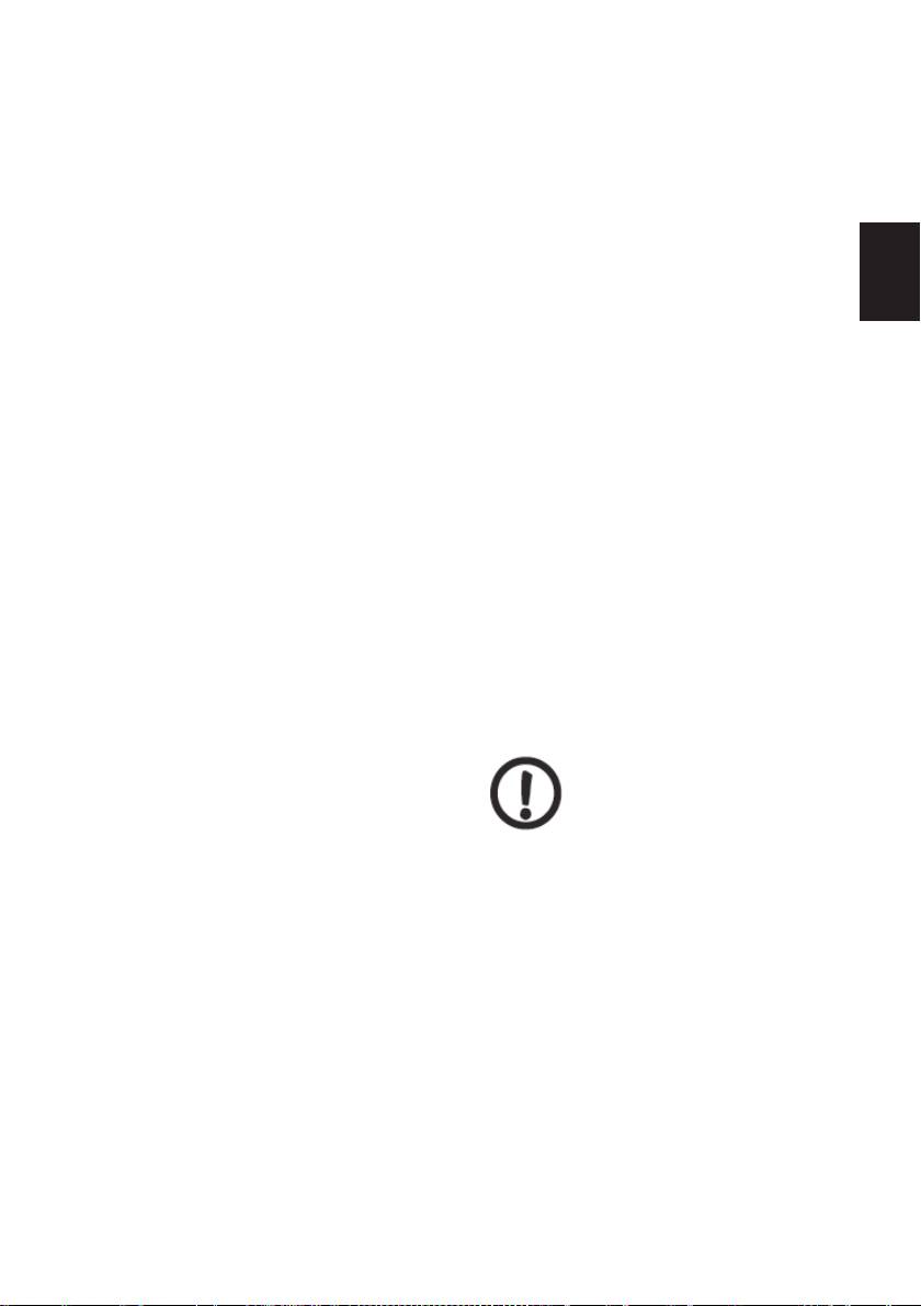
3. Delivery and handling
Pumps with lifting handles should be
raised using nylon straps and chains.
See diagram 2.
3.1 Delivery
The pump is shipped from the factory in
cardboard packaging with a wooden
GB
bottom that is purposely designed for
transportation with a forklift.
3.2 Handling
With the help of lifting
handles fitted on larger
motors, you can lift the
pump head (motor, motor mounting,
and impeller).
We must not lift the whole pump
using the lifting handles.
Pumps without lifting handles should be
raised using nylon straps. See diagram 1.
Diagram 2
4. Purpose of use
The pumps are intended to pump hot
and cold water in e.g.:
• heating systems,
• heating systems for apartment
blocks,
• air-conditioning devices, and
• cooling devices
• in residential areas, public buildings,
and in industry.
The pumps are further used for
pumping liquids and water supply for
e.g.:
• wash houses,
• systems for consumable water,
Diagram 1
and
• industrial systems.
-15-

For optimum performance, it is
5. Installation
important that the field of operation of
the device lies within the permissible
Danger of burns! With
area of operation for pumps.
devices pumping hot
medium, attention should be
paid that personnel do not come into
4.1 Pumped medium
contact with hot upper surfaces of
GB
the pump.
Clean, well flowing, non-aggressive,
and non-explosive without solid or long
5.1 Installing the electric motor
fibred constituents. The pumped
medium must not mechanically or
When installing the electric motor, you
chemically corrode the material of the
must:
pump.
• comply with the installation regulations
Examples:
requirements
• water of the central heating system
• determine if the anti-explosion
(it is recommended that the water
protection of the electric motor is
fulfils the requirements of accepted
suitable for the environment (zone,
water quality standards in heating
gas group, temperature class)
systems),
• determine how the environment
• cooling liquids,
affects the operation of the electric
• consumable water,
motor (aggressive environment,
• industrial liquids,
temperature, dust, etc.)
• softened water.
• comply with local and factory
Due to the different hydraulic effects of
peculiarities and requirements
pumping a liquid with different density
• ensure the use of proper tools and
and viscosity than water, you must
appliances
watch for the following:
• comply with the requirements for safe
• a larger fall in pressure,
operation
• a fall in the hydraulic effect,
• ensure the use of personal protective
• heightened power need of pump.
equipment.
In these cases, we must provide a
pump with larger motors. If in doubt,
5.2 Transport
please contact IMP PUMPS. Standard
Transportation of the pump must be
mounted seals are intended primarily
done professionally so that no parts of
for water.
the pump are at any time subjected to
If the water contains mineral or
disproportionate loads
.
synthetic oils or chemicals, or if
pumping liquid different from water, you
5.3 Storage
must choose a mechanical seal
accordingly.
The pump must be stored in a dry place with
no excessive dampness. With external
storage, the pump must be stored in
-16-
watertight packaging so that no parts can
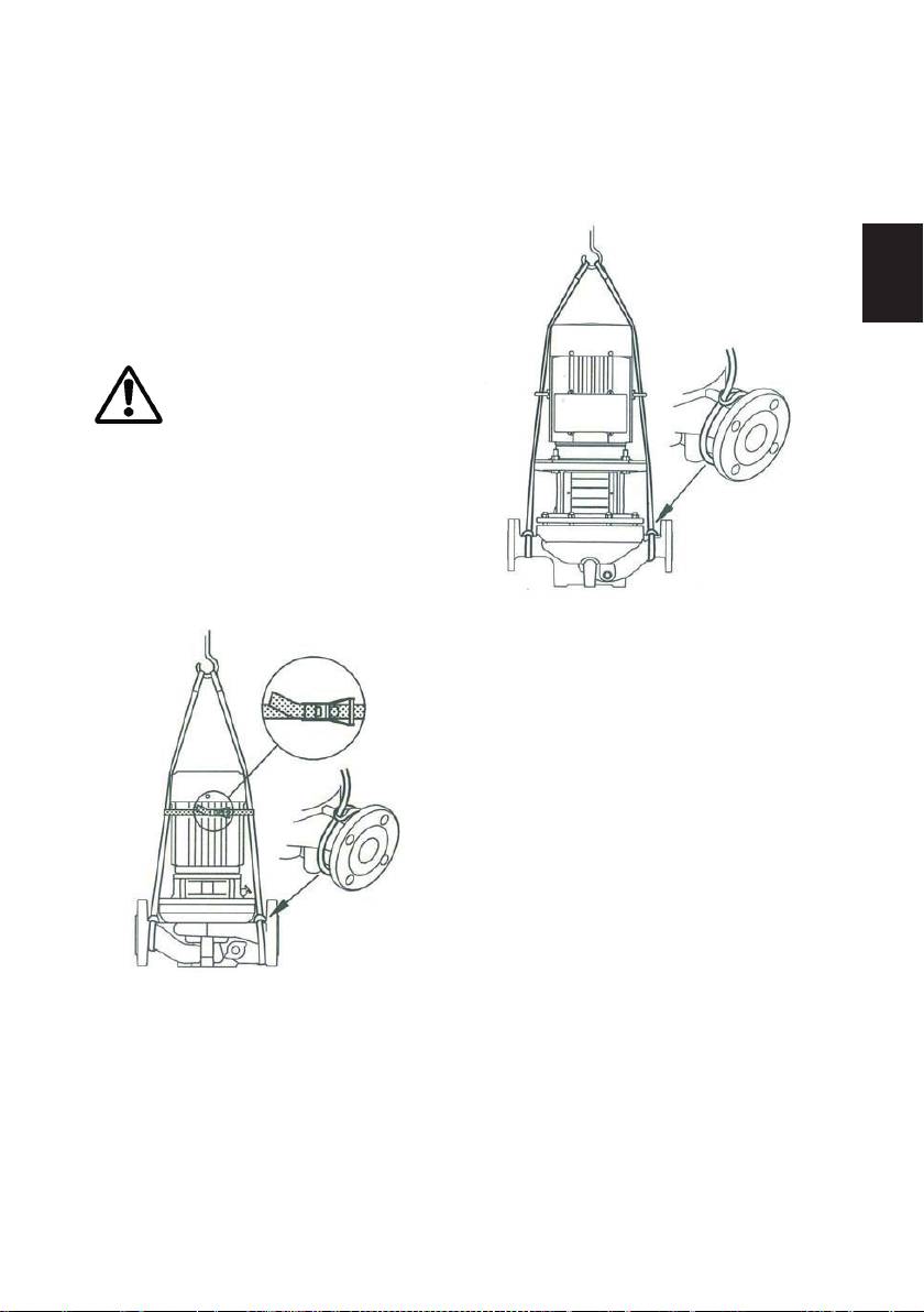
• When connected to the piping system,
come into contact with water.
the suction pipe must raise towards the
Special protection should be given to
pump to prevent the formation of an air
the bearing and neighbouring parts,
cushion. The formation of mechanical
which should be protected from
stresses on the pump and piping
moisture, dirt, and mechanical damage.
system must be prevented with the
GB
All safety precautions that inhibit
installation of bearers and supporters.
damage from moisture and dirt must be
• When planning, the proper selection of
complied with.
the nominal pipe diameters is extremely
5.4 Connection
important, as well as with the transition
from smaller to larger diameter pipes,
where the corners should not exceed 8
degrees. During larger operating
pressures, this should not exceed 5
degrees.
• The design engineers must also
provide for the installation of locking
and non-return valves. The
compensation elements will help avoid
inconveniences during temperature
changes. The piping system must not
Correct
be overburdened to avoid possible
leakages of the medium, which is
especially dangerous at higher
temperatures.
• Before installing the suction pipe to
the pump, all safety measures must be
completed that no impurities and other
residual solids enter the pump and
Correct
damage it. Therefore, prior to this, it is
necessary to clean and blow out the
pipe, or install a protective filter before
the pump, which will prevent the
penetration of harmful particles to the
functionally important parts of the
pump.
• The pump must not operate with
closed lock valves in a pressure
installation. This causes heightened
temperatures and the development of
steam, which can damage the pump.
Incorrect
-17-
To avoid this danger, the smallest flow
6. The start and end of
must run through the pump. We ensure
operation
this by installing a bypass or a
circulation to the vessel etc on the
6.1 Connecting electrical
pressure side of the pump. The flow
power
running through the pump must always
amount to 10% of the flow at the best
GB
Connection to electricity can
working point. We can find the flow and
only be done by and
flow height written on the display plate
electrician! It is necessary to comply
with the description of the pump.
with the VDE regulations 0100 and for
• On the pressure side of the piping
EX- protection 0165.
system, the system should be balanced
Compare the network voltage to the
to prevent the occurrence of vacuum.
information on the factory display plate
This is implemented with a special pipe
and choose the right settings.
of diameter 25 mm that is installed
When connecting, consider the
above the highest point of the reservoir
technical conditions for connecting
surface level.
to the local supplier of electrical
energy.
• When filling the system with the
We recommend a device for protecting
medium we must ensure that the
the motor.
suction piping and the pump are filled
with the medium and all the air is bleed
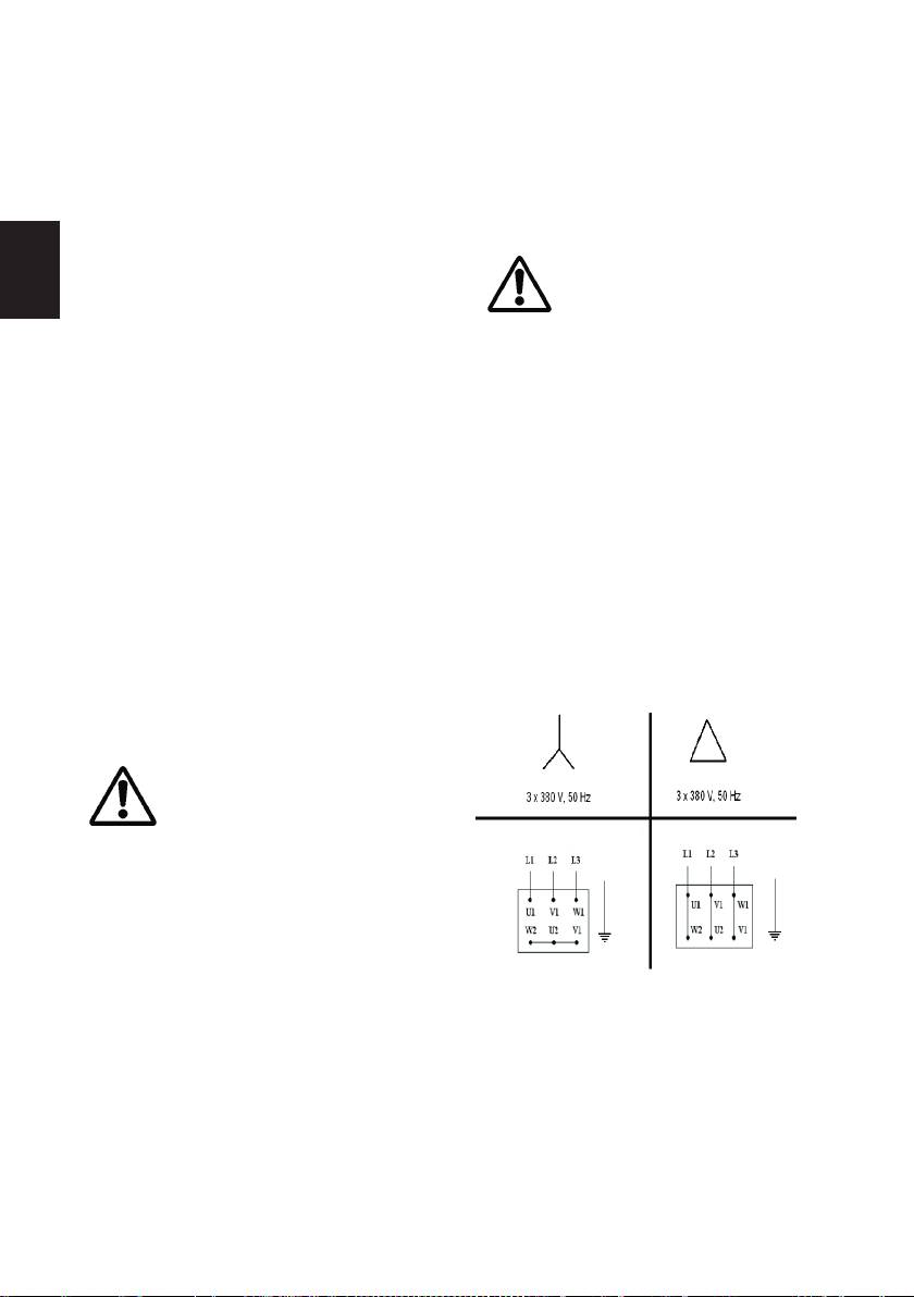
6.2 Connecting the motor
out. The lock valve from the suction
Connect the motor according to the
side, the inflow and outflow pipes, and
connection scheme shown in diagram
the lock valve for vacuum equalising
3.
should all be opened, all the while
controlling the values of the medium
flow, and close the sealing lock fittings.
• The pump may be
installed in an explosion
hazardous area II, but it is
compulsory to additionally
protect the pump against dry
running. This can be done, for
example, with the control of the
pump differential pressure or the
nominal motor current. The pump
should only be used for pumping a
mixture of water and glycol. The use
Diagram 3: Connection Y (high
of solvents is not permitted, as they
voltage) and connection ∆ (low
could damage the seals.
voltage).
-18-
• For three-phase electric
• With the increase of the medium
motors, the connections
temperature and possible leakage of
must be done exactly
the medium at the contacts protected
according to the manufacturer’s
by seals, care should be taken that the
instructions with setting the switching
screws are properly fastened, and in
time to 3 sec +- 30% as recommended.
the case of excessive dripping, the
GB
For special configurations of electric
screws should be tightened.
motors with anti-explosion protection,
• The shutdown of the pump should
increased security, or increased
also be implemented with certain rules.
temperature class, the connection must
Before the shutdown of the pipe, all
be made through the safety
switch.
valves on the pressure side of the
pump should be closed, this is essential
• The direction of the electric motor
in avoiding backpressure. It is also
rotation must be the same as the
important during shut-down that the
direction of the arrow on the pump
lock valves on the suction piping are
casing. Check by starting and
open.
immediately shutting down. If the
• Higher temperatures can be
direction of the motor rotations is
dangerous during dismantling, so the
opposite, change two phases L1, L2, or
flow of a cooler medium must be
L3 of the electric power with clips.
assured before stopping the pump.
The electric motor must be stopped
6.3 System conditions of the
steadily without any forcible
pump
interventions to the pump.
• The medium in the system
The pump together with the piping
must not have temperatures
system must have the following
that are too low due to
conditions assured:
potential freezing, which
• It must be filled with the medium.
must be prevented, including releasing
• The suction piping up to the pump
the medium from the system.
must have all the air bled out.
• Before dismantling the
• All additional connections that prevent
pump, it is necessary to
the flow of medium past the pump must
mechanically disconnect the
be closed.
cables from the connection
• The lock valves on the piping on the
cabinet and prevent a possible start-up
pressure side of the pump must be
of the pump. We close the valves on
closed.
the suction piping, control the lock on
• The protection of all rotating parts
the pressure side, and prepare the
must be implemented as required by
pump for dismantling.
the safety at work regulations.
• When starting the pump, the lock
valve on the pressure side of the pump
must slowly be opened, after the
electric motor has reached the highest
rotations.
-19-

or install spare parts from the
7. Maintenance, dismantling,
manufacturer of the pump.
damage to seals, spare, and
Dismantling the pump is also
composite parts
implemented according to certain rules:
• The lock valves on both the pressure
7.1 Maintenance
and suction sides must be closed.
• Maintenance must be done regularly
• The electrical supply must be
GB
according to the periodic plan of
switched off.
reviews. The pump must operate
• The medium in the system must be
calmly, without tremors, and always
cooled to a temperature that is not
filled with medium.
dangerous for work.
• Operating the pump at ambient
• Additional connections to the pipe
temperatures higher than 40°C is not
should be removed.
recommended. The temperature of the
• The screws between the pump
bearing (the external side of the bearing
casing and the driving generator
carrier) must not exceed 90°C. The
should be unscrewed and the two
maximum temperature of the medium is
separated.
given in the technical details on the
• With damage to the pump casing,
display plate of the pump.
loosen the screws on the flanges of
• With damaged mechanical seals, care
the piping and separate the entire
should be taken that the medium does
pump from the system.
not penetrate to the electric motor, as it
• With excessive corrosion on the
can cause permanent damage. It is
connection contacts, apply any
necessary to inspect the other seals
anticorrosive agent for removing rust.
(sheets, seal), and watch for the
occurrences of leaks at the contacts.
7.2 Damage to seals
When the seals are worn out, they need
Damage to the mechanical seal is a
to be replaced.
sign that it should be replaced entirely.
• If the pump remains idle for a longer
During dismantling care should be
period, it is recommended to start-up
taken not to damage the contact
the pump for 5 minutes weekly
patches and seats were the mechanical
according the same instructions as for
seal is fitted.
the initial start-up.
• If there is damage to parts that are
• The inspection of bearings should be
functionally important for the sealing
more frequent in adverse operating
of the mechanical seal, it is necessary
conditions. The manufacturer foresees
to change them with the original
a minimum of 20000 hours of operation.
manufacturer’s parts. Before re-fitting
Interventions to the pump must be done
the mechanical seal, all contact
by a professional or maintenance
surfaces should be cleaned from dirt
service.
and impurities.
• With mechanical damage to the
• It is necessary to control the
original parts of the pump, it is
installation measurements, as well as
necessary to call an authorised service,
the seal measurements, centreline,
-20-

and the parallelism between the shaft
• Flat surfaces must not be unclean or
and the casing.
soiled with oils, but must be dry, dust
• The shaft must be treated within the
free and carefully installed.
Rmax 5 ľm (Ra max=0.8 or N6)
• For the MG variation, the elastic
values, other surfaces that are
materials should be moistened with
important for the incorporation must
water and pushed circularly onto the
GB
be treated better than Rz 10 ľm (Ra
shaft. Oils and lubricants must not
max=2.5 or N7/N8).
be used! Pressure may be applied
• All edges, plates, and part surfaces
only to the edges of the rounds parts.
being exposed to the mechanical seal
After installing all the parts, it is
must be smoothened or rounded (e.g.
necessary to check if the seal has
2 mm x 30 degrees by DIN 24960).
adapted well.
• Installation must be done in
• The regulatory materials do not
cleanliness and very carefully. No
require maintenance if we know the
force may be used, as there is the
overlap position. A forcible circulation
danger of plastic deformation,
of the pump where the seal is
cracking, and breakage of the ceramic
installed is necessary with warm
material.
medium to prevent deposits on the
• The installation or dismantling
single seals in a compressed state.
sequence of the mechanical seal
• All the air in the seal casing for
should be adapted to the pump
internal use must be carefully bleed
construction.
out, and the mechanical seal must be
• To reduce friction during installation
completely submersed in the medium
all plate rubbers that are laid on the
(there can be no dry run!)
shaft should be moistened with water
or alcohol, or they should be covered
7.3 Spare parts
with silicone grease.
Please contact the manufacturer or
• There are special instructions for
maintenance service for spare parts,
storage and handling of elastic
and give the pump type, serial number,
materials: Natural rubber must not
necessary part or half product for
come into contact with mineral-
replacement, and the desired amount in
based oils and lubricants!
your order.
• The stator is not foreseen for plastic
deformation as breakage can occur.
-21-
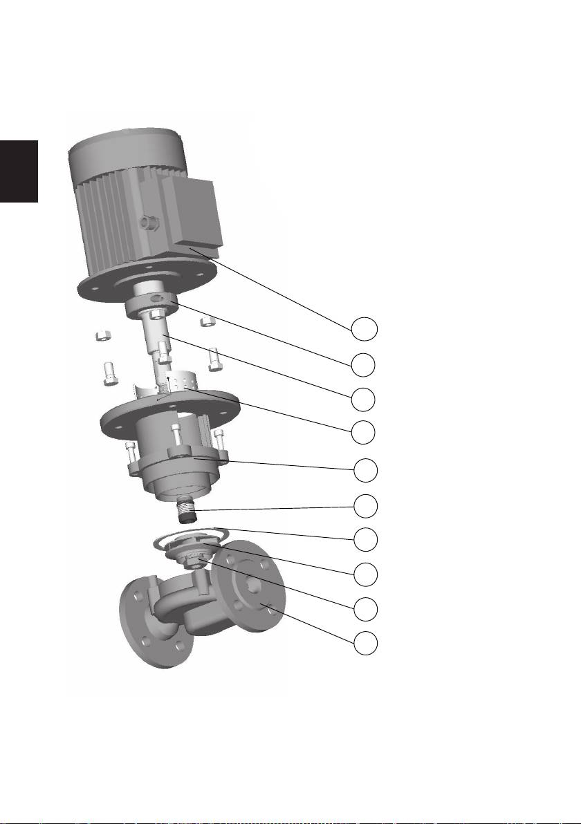
7.4 Composite parts of the pump CL 40, 50, 65, 80, 100
GB
-22-
1. Electric motor
2. Clamp
3. Shaft
4. Nut
5. Bolt
6. Protective metal sheet
7. KU console (for 2 full console
8. Allen bolt
9. Mechanical seal
10. Seal
11. Impeller
12. Pump casing
E-mail: Info@imp-pumps.com
+ separating wall)
Fax: +386 1 2806 460
www.imp-pumps.com
Tel: +386 1 2806 418
IMP PUMPS D.O.O.
ZAGORICA 18
SLOVENIA
1292 IG
1-HIDRAVLIČNO OHIŠJE
2-MATICA
3-TEKAČ
4-PLOŠČATO TESNILO
5-DRSNO TESNILO
6-KONZOLA (pri 2-polnih
Konzola + Prekatna stena)
7-ZAŠČITNA PLOŠČICA
8-NATIČNA GRED
9-OBJEMKA
10-ELEKTROMOTOR
10
9
8
7
6
5
4
3
2
1
1. Pump casing
2. Nut
3. Impeller
4. Seal
5. Mechanical seal
6. Console (for 2 poles -Console +
separating wall)
7. Protective plate
8. Shaft
9. Clamp
10. Electric motor
Оглавление
- Centrifugalne črpalke CL 40, 50, 65, 80, 100 EEx izvedba Centrifugal pumps CL 40, 50, 65, 80, 100 EEx configuration Kreiselpumpen CL 40, 50, 65, 80, 100 EEx-Ausfertigung Центробежные насосы CL 40, 50, 65, 80, 100 Конфигурации EEx Centrifugalne crpke CL 40, 50, 65, 80, 100 EEx izvedba
- SLO
- GB
- D
- CRO
- CRO
- RU
- SLO
- GB
- D
