Ford WESTFALIA 388: инструкция
Раздел: Бытовая, кухонная техника, электроника и оборудование
Тип: Автомобиль
Инструкция к Автомобилю Ford WESTFALIA 388
GIS1 Retention: 27.60 35
SKAM5J 19D520 BA HM02 E 12346495 000 26/04/2010 1/43
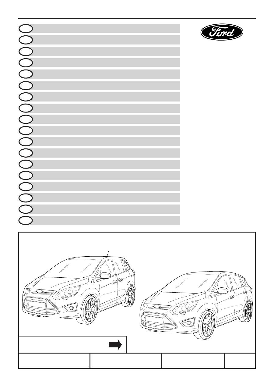
C-MAX 08/2010
WESTFALIA 307 388
e13*94/20*3108
DXA
©
Copyright Ford 2010
Printed Copies are uncontrolled
Expert Fitment Required
Montage durch Fachwerkstatt erforderlich
Montaje sólo por el concesionario
Montage par spécialiste nécessaire
E’ necessario in officina specializzata
Especialista em montagem requerido
Montage door vakman nodig
Montage ved professionelt værksted påkrævet
Nødvendig med montering fra fagvegverksted
Verkstadsmontage erfordras
Asennus tarpeen merkkikorjaamossa
Montáž ve specializované dÍlně nutná
A szereléshez szakműhely kell
Konieczny montaż przez warsztat specjalistyczny
Nα τοποθεί απ συνεργείο
Uzman servis kuruluμu taraf∂ndan monte
edilmesi gerekmektedir
Монтаж должен проводиться только в
специализированных мастерских
Montajul trebuie efectuat de un atelier de specialitate
Subject to alteration without notice
Technische Änderungen vorbehalten
Reservadas modificaciones técnicas
Sous réserve de modifications techniques
Con riserva di apportare modifiche tecniche
Reservamo-nos o direito a alteraćões técnicas
Technische wijzigingen voorbehouden
Med forbehold for tekniske ĺndringer
Tekniske forendringer forbeholdes
Med reservation för tekniska ändringar
Tekniset muutokser pidätetään
Technické zmeny vyhrazeny
A változtatások technika jogát fenntartjuk
Zmiany techniczne zastrzeżone
Επιφυλασσ μεθα για αλλαγές
Teknik deπiμiklikler yapma hakk∂ sakl∂d∂r
Мы оставляем за собой право на
технические изменения
Ne rezervåm dreptul la modificåri tehnice
INSTALLATION INSTRUCTIONS
TOW BAR RETRACTABLE
EINBAUANLEITUNG
AUSFAHRBARE ANHÄNGEVORRICHTUNG
NOTICE DE MONTAGE
DISPOSITIF D’ATTELAGE RETRACTABLE
NOTICE DE MONTAGE
DISPOSITIVO DI RIMORCHIO ESTRAIBILE
INSTRUÇÕES DE MONTAGEM
ENGATE DE REBOQUE EXTRAÍVEL
INBOUW-INSTRUCTIE
UITSCHUIFBARE TREKHAAK
MONTERINGSVEJLEDNING
UDTRÆKKELIGT ANHÆNGERTRÆK
MONTERINGSVEILEDNING
TILHENGERKOPLING SOM KAN TREKKES UT
MONTERINGSANVISNING
UTKÖRBAR SLÄPVAGNSKOPPLING
ASENNUSOHJE
ULOSVEDETTÄVÄ VETOKOUKKU
NÁVOD K MONTÁŽI
VYSOUVACÍ ZÁVĚSNÉ ZAŘÍZENÍ
BESZERELÉSI UTASÍTÁS
KIHAJTHATÓ UTÁNFUTÓ-VONTATÓBERENDEZÉS
INSTRUKCJA INSTALOWANIA
WYSUWANY HAK HOLOWNICZY
ΟΔΗΓΙΕΣ TOΠΟΘΕΤΗΣΗΣ
ΕΞΕΡΧΟΜΕΝΟΣ ΚΟΤΣΑΔΟΡΟΣ
D
GB
F
E
I
NL
P
DK
N
S
SF
CZ
H
PL
GR
INSTRUCCIONES DE MONTAJE
DISPOSITIVO DE REMOLQUE TELESCÓPICO
MONTAJ TAL∑MATLARI
A
AÇ
ÇIIL
LIIP
P K
KA
AP
PA
AT
TIIL
LA
AB
B∑∑L
L∑∑R
R S
SÜ
ÜR
RG
GÜ
ÜL
LÜ
Ü R
RÖ
ÖM
MO
OR
RK
K Ç
ÇE
EK
KM
ME
E T
TE
ER
RT
T∑∑B
BA
AT
TII
ИНСТРУКЦИЯ ПО МОНТАЖУ
ВЫДВИЖНО Е ПРИЦЕПНОЕ УСТРОЙСТВО
TR
RUS
INSTRUCØIUNI DE MONTAJ
D
DIIS
SP
PO
OZ
ZIIT
TIIV
V D
DE
E R
RE
EM
MO
OR
RC
CA
AR
RE
E R
RE
ET
TR
RA
AC
CT
TA
AB
BIIL
L
RO
© Copyright Ford 2010
HM02 E 12346495 000
SKAM5J 19D520 BA
2/43
INSTALLATION INSTRUCTIONS –
RETRACTABLE TOW BAR
Type:
307 388
D-value:
10,0 kN
Bearing load:
75 kg
Manufacturer:
Westfalia Automotive GmbH
Am Sandberg 45, D-33378
Rheda-Wiedenbrück
EEC type approval no.:
e13*94/20*3108
Area of application:
Ford C-Max 08/2010
➜
Off. type designation:
DXA
Note:
Fitting is to be executed in accordance with these
instructions.
When using the trailer hitch, always observe the
manufacturer's data regarding trailer load and vertical
load. The figures stated for the trailer hitch must not
be exceeded.
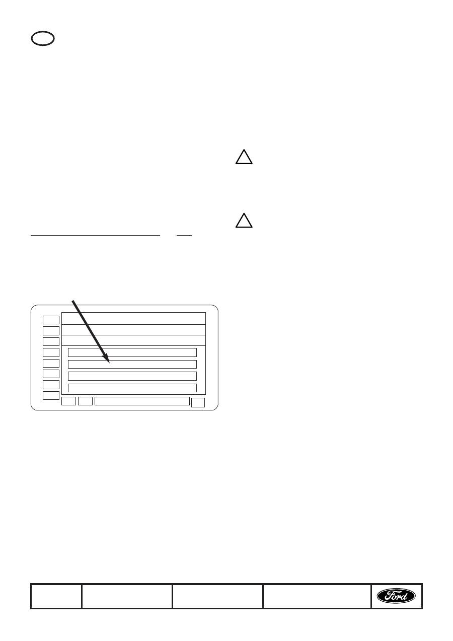
Formula for ascertainment of D-value:
The maximum permissible combined weight of vehicle and
trailer must not be exceeded. The maximum permissible
weight for the car-trailer combination is stated on the
vehicle's identification plate. Your Ford dealer will be
pleased to help you if required.
Before using the coupling device, the correct trailer
electrical kit must be installed.
It is recommended to install the electrical kit before fitting
the trailer coupling.
In the area of the contact surfaces, undersealing, anti-
corrosion wax and noise-deadening material must be
removed. If necessary, apply corrosion protection according
to Ford Service guidelines.
Note: The following delivered equipment must be fitted
with the tow bar (cover kit: your Ford dealer would be
pleased to help you):
AM5J-313A16-A*
Note: For motor vehicles with keyless entry function the
following delivered equipment must also be fitted (aerial
fastening kit: your Ford dealer would be pleased to help
you):
AM3M5J-10K015-A*
GB
Disconnect earth lead from battery. Jack the vehicle.
Remove rear bumper (X1) and impact strip as per manual.
The impact strip is no longer required.
Screw the nuts of the impact strip (6 x X2) back onto the
threads on the rear wall panel and tighten to the prescribed
torque.
Release aerial (X3), if fitted, from the bumper rail. Fastening
parts are no longer needed.
Push the side members (B + C) of the tow bar into the side
rails and screw up handtight with braces (2 x D) and bolts
(4 x E).
Note: The bolts and screw threads used to bolt
the tow bar to the bodywork must be free from oil
and grease!
Align cross member (A) of the tow bar with the side mem-
bers (B + C) and screw up bolts with washers (4 x F + 4 x G)
handtight.
Before tightening the bolts (E) align the braces (2 x D) as
illustrated.
Note: The braces must not rest on the metal plate
flange!
First tighten the screws (4 x E) on the side members to the
specified torque.
Then tighten the screws (4 x F) on the cross member to the
specified torque.
Fasten aerial (X3), if fitted, to the top side of the tow bar's
cross member with the foam part and cable ties
(AM3M5J-10K015-A*) as illustrated.
Remove carpet from under the side panelling, rear right, as
per the workshop manual.
On grand motor vehicles, remove blind plug from the floor
panel. The blind plug is no longer required.
On compact motor vehicles, drill a 28.5 mm diameter hole in
the floor panel at the punched point from below. Debur the
hole after drilling and apply corrosion protection as per Ford
guidelines.
Insert dowels for bracket (3 x I) into the holes in the side
wall as illustrated.
Position brackets (K1 or K2) and fasten them to the side wall
with bolts (3x H).
Feed electrical leads and Bowden cable of the tow bar (A)
through the hole in the floor panel as far as the rubber
grommet.
Behind the right-hand side panelling, remove the supply
lead (X4) from the 12 V socket and connect it to the mat-
ching two-pole plug of the tow bar's electrical lead.
Then connect the two-pole jack of the tow bar’s electrical
lead to the 12 V plug socket. Plug the four-pole jack for the
buzzer (small cable cross-section) into the back of the
control unit (L).
Note: To connect the Bowden cable (A) to the control
unit (L), the silver marking on the hand wheel and the
arrow on the housing must be aligned as illustrated!
Then insert the Bowden cable into the control unit as far as
it will go and push in the clip to lock in position. Push the
control unit (L) onto the bracket (K1 or K2) until it clicks in.
Note: Check that the rubber grommet is firmly seated in
the floor panel!
Insert the clamping shoes of the free electrical lead (A) into
the housing (N) as illustrated and turn the straps down.
Insert the fuse (M) and fasten the fuse holder (N) to the
Bowden cable with the cable tie as illustrated.
XXXX kg
Trailer mass [kg] x gross vehicle mass [kg]
9,81
Trailer mass [kg] + gross vehicle mass [kg]
1000
x
= D [kN]
! !
EINBAUANLEITUNG – AUSFAHRBARE
ANHÄNGEVORRICHTUNG
Typ:
307 388
D-Wert:
10,0 kN
Stützlast:
75 kg
Hersteller:
Westfalia Automotive GmbH
Am Sandberg 45, D-33378
Rheda-Wiedenbrück
EWG Typgen.-Nr.:
e13*94/20*3108
Verwendungsbereich:
Ford C-Max 08/2010
➜
Amtl. Typbezeichnung:
DXA
Hinweis:
Der Anbau hat nach dieser Anbauanweisung zu erfolgen.
Eine Anbauabnahme gemäß §19 (3) der StVZO ist nicht
erforderlich. Eine Anbauabnahme hat im Rahmen der
Erteilung der Europäischen Betriebserlaubnis gemäß
94/20/EC Anlage VII 2.1.1 stattgefunden.
Die Betriebserlaubnisdes Fahrzeuges erlischt nicht.
Gemäß § 27 (1) StVZO sind Änderungen der zuständigen
Zulassungsbehörde erst bei deren nächster Befassung mit
den Fahrzeugpapieren unter Einreichung des Fahrzeugbriefs
und Fahrzeugscheins oder der Anhängerverzeichnisse nach
§24 Satz 3 oder des Nachweises nach §18 Abs. 5 sowie der
Unterlagen nach § 19 Abs. 3 oder 4 zu melden.
Achtung: Abweichend davon müssen Änderungen der
zulässigen Achslasten, des Gesamtgewichts, der Nutz-/
Sattel-/ Aufliege- oder Anhängelast unverzüglich gemel-
det werden.
Diese Bescheinigung ist den Fahrzeugpapieren beizulegen,
um sie zuständigen Personen auf Verlangen vorzuzeigen.
Für den Fahrbetrieb sind die Angaben des Fahrzeug-
herstellers bezüglich Anhängelast und Stützlast maßgebend,
wobei die Werte der Anhängevorrichtung nicht überschritten
werden dürfen.
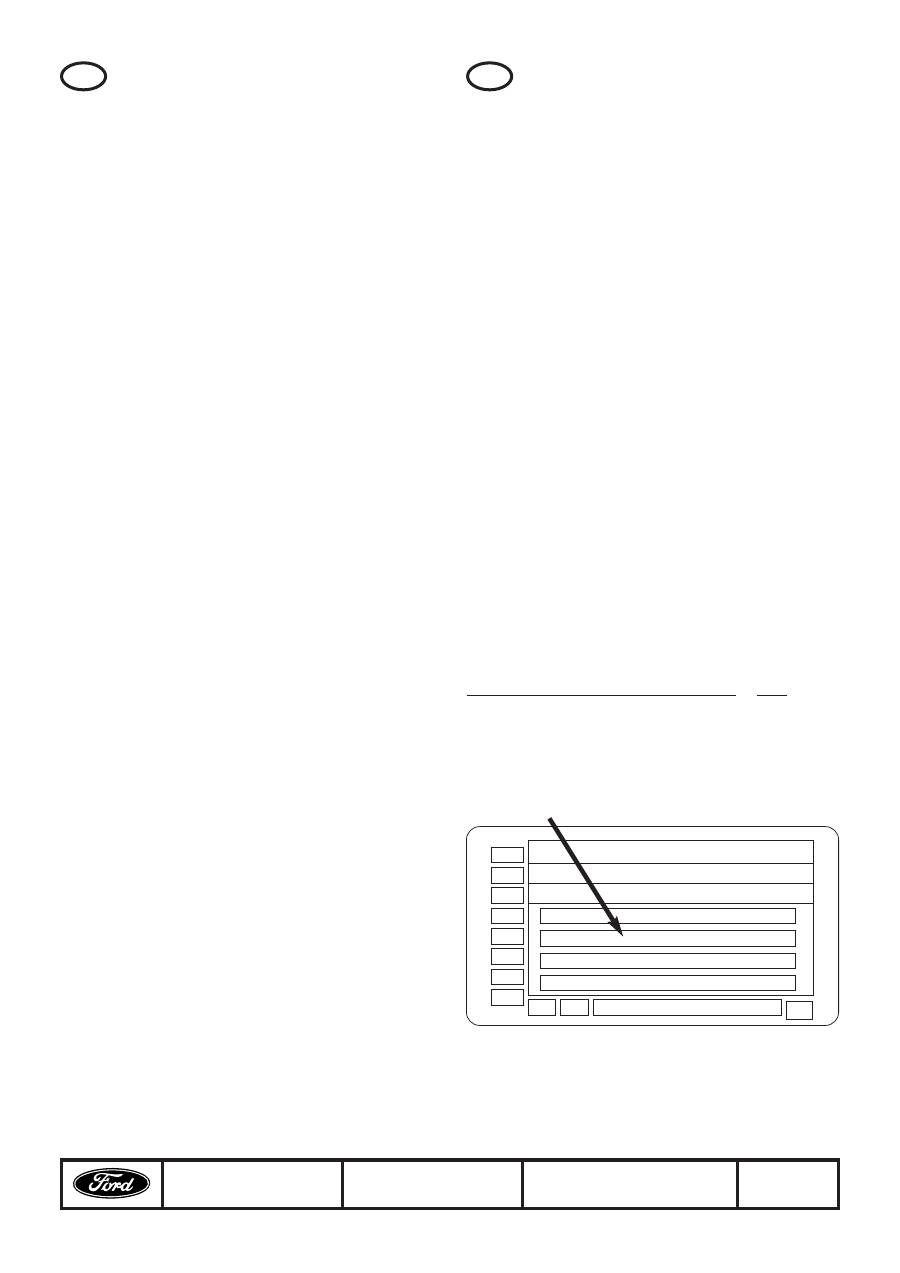
Formel für D-Wert Ermittlung:
Das höchstzulässige Gesamtgewicht der Kombination
Fahrzeug und Anhänger darf nicht überschritten werden. Die
zulässige Gewichtsangabe für das Gespann ist auf dem
Fahrzeug-Typenschild angegeben. Ihr Ford Händler ist Ihnen
gerne behilflich.
Zum Betreiben der Anhängevorrichtung ist der gleichzeitige
Einbau eines Elektrobausatzes erforderlich. Es wird
empfohlen, den Elektrobausatz vor dem Einbau der
Anhängevorrichtung zu installieren.
© Copyright Ford 2010
HM02 E 12346495 000
SKAM5J 19D520 BA
3/43
D
XXXX kg
Anhängelast [kg] x Kfz Gesamtgewicht [kg]
9,81
Anhängelast [kg] + Kfz Gesamtgewicht [kg]
1000
x
= D [kN]
Then check that the release mechanism of the retractable
tow bar is working properly. The way to do this is described
in the motor vehicle manual.
Attach the tow bar's electrical lead to the Bowden cable
with cable ties (2 x O). Fasten the Bowden cable to the
cross member of the tow bar and the motor vehicle with
large cable ties (2 x P) as illustrated.
Using the embossing on the back as a guide, cut a 121 mm
diameter circular hole in the carpet of the side panelling.
Then cut approx. 15 mm-long straight slits running radially
outwards from the top and bottom of the hole (using the
embossing as a guide). The slits are to prevent the cover
from twisting.
Insert the front frame of the cover (AM5J-313A16-A*) into
the hole in the carpet from inside. Then fit the rear frame of
the cover (AM5J-313A16-A*) onto the back of the carpet
and snap it into the front frame.
Fit carpet as per workshop manual and insert cap as illu-
strated.
Note: Before inserting the cap the key must be removed
from the hand wheel of the control unit!
Note:
At this point finish installing the electrical kit.
Replace dismantled or loosened parts as described in the
workshop manual.
Reconnect aerial (X3), if fitted, and connect the earth lead to
the battery.
Operating notes:
The coupling ball must be kept clean and well greased (*).
(*) Exception:
When stabilisers are in use which act on the coupling ball,
pro-ceed according to the instructions of the manufacturer
of the stabilisers. When stabilisers are in use, the coupling
ball must be inspected for wear at regular intervals.
As soon as a coupling ball diameter of 49.0 mm or smaller
has been reached at any point, the towing device
must no longer be used in trailer operation; if necessary,
the towing device must be renewed.
The unladen weight of the vehicle will increase by appr.
25 kg following mounting of the towing device.
GB
© Copyright Ford 2010
HM02 E 12346495 000
SKAM5J 19D520 BA
4/43
Im Bereich der Anlageflächen sind Materialien zur
Bodenabdichtung, zum Rostschutz und zur
Geräuschdämmung zu entfernen. Falls erforderlich ist
Korrosionsschutz gemäß Ford-Richtlinien aufzubringen.
Achtung: Zusammen mit der ausfahrbaren
Anhängevorrichtung muss zusätzlich folgender
Lieferumfang verbaut werden (Kit Abdeckung, Ihr Ford
Händler ist Ihnen gerne behilflich):
AM5J-313A16-A*
Achtung: Für Fahrzeuge mit 'keyless entry' Funktion
muss zusätzlich folgender Lieferumfang verbaut werden
(Kit Antennenbefestigung, Ihr Ford Händler ist Ihnen
gerne behilflich):
AM3M5J-10K015-A*
Massekabel von Batterie abklemmen. Fahrzeug anheben.
Hinteren Stossfänger (X1) und Prallkörper gemäß
Werkstatthandbuch ausbauen. Prallkörper wird nicht mehr
benötigt.
Die Muttern des Prallkörpers (6x X2) wieder auf die Gewinde
am Rückwandblech schrauben und mit dem vorgeschriebe-
nen Drehmoment festziehen.
Wo vorhanden, Antenne (X3) vom Stossfängerträger lösen.
Befestigungsteile werden nicht mehr benötigt.
Die Seitenteile der Anhängevorrichtung (B + C) in die
Längsträger einschieben, mit Gegenlagen (2x D) ausrichten
und Schrauben (4x E) handfest eindrehen.
Achtung: Die Verschraubung der Anhänge-
vorrichtung an die Karosse hat frei von Öl und Fett
an Schrauben und Gewindegängen zu erfolgen!
Den Querträger der Anhängevorrichtung (A) mit den
Seitenteilen (B + C) ausrichten und Schrauben mit
Unterlegscheiben (4x F + 4x G) handfest eindrehen.
Vor dem Festziehen der Schrauben (E) die Gegenlagen
(B + C) wie abgebildet ausrichten.
Achtung: Die Gegenlagen dürfen nicht auf dem
Blechflansch aufliegen!
Zuerst die Schrauben an den Seitenteilen (4x E) mit dem vor-
geschriebenen Drehmoment festziehen.
Danach die Schrauben am Querträger (4x F) mit dem vorge-
schriebenen Drehmoment festziehen.
Wo vorhanden, Antenne (X3) wie abgebildet mit Schaumteil
und Kabelbindern (AM3M5J-10K015-A*) auf der Oberseite
des Querträgers der Anhängevorrichtung befestigen.
Teppich unter der Seitenverkleidung hinten rechts gemäß
Werkstatthandbuch ausbauen.
Bei Grand Fahrzeugen Blindstopfen im Bodenblech entfer-
nen. Blindstopfen wird nicht mehr benötigt.
Bei Compact Fahrzeugen an der gekörnten Stelle von unten
in das Bodenblech ein Loch Durchmesser 28,5 mm bohren.
Nach dem Bohren Grate entfernen und Korrosionsschutz
gemäß Ford-Richtlinien aufbringen.
Dübel für Halter (3x I) wie abgebildet in die Öffnungen der
Seitenwand einstecken.
Halter (K1 oder K2) ansetzen und mit Schrauben (3x H) an
der Seitenwand befestigen.
Elektrische Leitungen und Bowdenzug der
Anhängevorrichtung (A) bis zur Gummitülle durch das Loch
im Bodenblech führen.
Hinter der rechten Seitenverkleidung die Zuleitung (X4) von
der 12V Steckdose abziehen und mit dem passenden zwei-
poligen Stecker der elektrischen Leitung der
Anhängevorrichtung verbinden.
D
Anschließend die zweipolige Buchse der elektrischen
Leitung der Anhängevorrichtung an die 12V Steckdose
anschließen. Die vierpolige Buchse für den Summer (kleiner
Kabelquerschnitt) auf der Rückseite der Bedieneinheit (L)
einstecken.
Achtung: Zum Verbinden des Bowdenzuges (A) mit der
Bedieneinheit (L) müssen die silberne Markierung am
Handrad und der Pfeil auf dem Gehäuse wie abgebildet
ausgerichtet sein!
Anschließend den Bowdenzug bis zum Anschlag in die
Bedieneinheit einführen und durch Einschieben des Clip
verriegeln. Die Bedieneinheit (L) bis zum Einrasten auf den
Halter (K1 oder K2) schieben.
Achtung: Gummitülle auf festen Sitz im Bodenblech
überprüfen!
Die Klemmschuhe der freien elektrischen Leitung (A) wie
abgebildet in das Gehäuse (N) einführen und Laschen
umlegen. Die Sicherung (M) einstecken und den
Sicherungshalter (N) wie abgebildet mit Kabelbinder (O) am
Bowdenzug befestigen.
Anschließend die Auslösung der ausfahrbaren
Anhängevorrichtung auf mechanische Funktion prüfen.
Die Bedienung ist im Fahrzeughandbuch beschrieben.
Elektrische Leitung der Anhängevorrichtung mit
Kabelbindern (2x O) am Bowdenzug befestigen. Bowdenzug
mit großen Kabelbindern (2x P) wie abgebildet am
Querträger der Anhängevorrichtung und am Fahrzeug
befestigen.
In den Teppich der Seitenverkleidung entlang der Prägung
auf der Rückseite ein kreisrundes Loch Durchmesser
121mm schneiden. Anschließend das Loch oben und unten
(Prägungen) radial ca. 15mm gerade einschneiden. Die
Schlitze dienen als Verdrehsicherung für die Abdeckung.
Den vorderen Rahmen der Abdeckung (AM5J-313A16-A*)
wie abgebildet von innen in das Loch im Teppich einsetzen.
Anschließend den hinteren Rahmen der Abdeckung
(AM5J-313A16-A*) auf der Rückseite des Teppichs
anbringen und mit dem vorderen Rahmen verrasten.
Teppich gemäß Werkstatthandbuch einbauen und Deckel
wie abgebildet einsetzen.
Achtung: Vor dem Einsetzen des Deckels muss der
Schlüssel vom Handrad der Bedieneinheit abgezogen wer-
den!
Hinweis:
An dieser Stelle die Installation des Elektrobausatzes zu
Ende führen.
Ausgebaute oder gelöste Teile gemäß Werkstatthandbuch
wieder einbauen.
Wo vorhanden, Antenne (X3) wieder anschließen und
Massekabel an Batterie anklemmen.
Betriebshinweise:
Die Kupplungskugel ist sauber zu halten und zu fetten (*).
(*) Ausnahme:
Bei Verwendung von Stabilisierungseinrichtungen, die auf
die Kupplungskugel wirken, muss nach den Anweisungen
des Herstellers der Stabilisierungseinrichtung vorgegangen
werden. Bei Verwendung von Stabilisierungseinrichtungen
ist die Kupplungskugel in regelmäßigen Abständen auf
Verschleiß zu untersuchen. Sobald an einer beliebigen Stelle
ein Kupplungskugel-Durchmesser von 49,0 mm oder kleiner
erreicht ist, darf die Anhängevorrichtung nicht mehr im
Anhängerbetrieb benutzt werden. Gegebenenfalls ist die
Anhängevorrichtung zu erneuern.
Das Leergewicht des Fahrzeugs erhöht sich nach Montage
der Anhängevorrichtung um ca. 25 kg.
! !
© Copyright Ford 2010
HM02 E 12346495 000
SKAM5J 19D520 BA
5/43
INSTRUCCIONES DE MONTAJE –
DISPOSITIVO DE REMOLQUE
TELESCÓPICO
Tipo:
307 388
Valor "D":
10,0 kN
Carga vertical:
75 kg
Fabricante:
Westfalia Automotive GmbH
Am Sandberg 45, D-33378
Rheda-Wiedenbrück
N.º de homologación CEE: e13*94/20*3108
Campo de aplicación:
Ford C-Max 08/2010
➜
Den. oficial del tipo
de vehículo:
DXA
Nota:
El montaje se debe realizar conforme a las presentes
instrucciones de montaje.
Para la conducción son determinantes las indicaciones del
fabricante del vehículo con respecto a la carga del remolque
y la carga en la bola; no se deben sobrepasar los valores
del dispositivo de remolque.
Fórmula para determinar el valor D:
El peso máximo total admisible de la combinación de
vehículo y remolque no se debe sobrepasar. La indicación
del peso admisible para el conjunto de vehículo de tracción
y remolque está indicada en la placa de características del
vehículo. Su concesionario Ford le ayudará con mucho
gusto.
Antes de poner en uso el acoplamiento de remolque, se
tiene que instalar el kit eléctrico correspondiente al
acoplamiento de remolque.
Se recomienda instalar el equipo eléctrico antes de montar
el dispositivo de remolque.
En la zona de las superficies de contacto, se tienen que
retirar los materiales para la estanqueidad de los bajos, la
protección anticorrosiva y el aislamiento acústico.
En caso de necesidad, aplicar protección anticorrosiva
según las directivas Ford.
Atención: Deberá montarse adicionalmente el siguiente
volumen de suministro junto con el dispositivo de remol-
que telescópico (kit de cubierta, su concesionario Ford
le ayudará con mucho gusto):
AM5J-313A16-A*
E
XXXX kg
Carga remolcada [kg] x peso total del vehículo [kg]
9,81
Carga remolcada [kg] + peso total del vehículo [kg]
1000
x
= D [kN]
Atención: Para vehículos con función de apertura sin
llave deberá montarse adicionalmente el siguiente volu-
men de suministro (kit de sujeción de antena, su conce-
sionario Ford le ayudará con mucho gusto):
AM3M5J-10K015-A*
Embornar el cable de masa en la batería. Elevar el vehículo.
Desmontar el parachoques trasero (X1) y el cuerpo deflector
siguiendo el manual del taller. El cuerpo deflector ya no se
volverá a necesitar.
Atornillar de nuevo las tuercas del cuerpo deflector (6x X2) a
las roscas de la chapa de la pared exterior y apretarlas con
el par de apriete prescrito.
Retirar las antenas (X3) que haya del soporte del paracho-
ques. Las piezas de sujeción ya no se volverán a necesitar.
Insertar las piezas laterales (B + C) del dispositivo de remol-
que en los soportes longitudinales, alinear con las placas de
sentido opuesto (2x D) y atornillar manualmente los tornillos
(4x E).
Atención: Al realizar el atornillamiento del disposi-
tivo de remolque a la carrocería, deben estar lib-
res de aceite y grasa los tornillos y las roscas.
Alinear el travesaño (A) del dispositivo de remolque con las
piezas laterales (B + C) y atornillar manualmente los tornillos
con las arandelas (4x F + 4x G).
Antes de apretar los tornillos (E) deben alinearse las placas
de sentido opuesto (2x D), tal como se muestra en la figura.
Atención: ¡Las placas de sentido opuesto no
deben quedar sobre las bridas de la chapa!
En primer lugar, apretar los tornillos (4x E) en las piezas
laterales con el par de apriete prescrito.
A continuación, apretar los tornillos (4x F) en el travesaño
con el par de apriete prescrito.
Fijar, tal como se muestra en la figura, las antenas (X3) con
la pieza de espuma y las cintas de sujeción para cables
(AM3M5J-10K015-A*) a la parte superior del travesaño del
dispositivo de remolque.
Desmontar la alfombra del revestimiento lateral trasero
derecho siguiendo el manual del taller.
En los vehículos Grand, retirar los tapones ciegos de la
chapa del suelo. Los tapones ciegos ya no se volverán a
necesitar.
En los vehículos Compact, realizar un agujero de 28,5 mm
de diámetro desde abajo en la chapa del suelo en la parte
granulada. Después de taladrar, retirar las rebabas y aplicar
protección anticorrosiva según las directrices Ford.
Insertar tacos para los soportes (3x I) en los orificios de la
pared lateral, tal como se muestra en la figura.
Colocar el soporte (K1 o K2) y fijarlo con tornillos (3x H) a la
pared lateral.
Guiar el cable eléctrico y el cable Bowden del dispositivo de
remolque (A) a través del agujero de la chapa del suelo
hasta la arandela de goma.
Retirar la línea de conexión (X4) de la base de enchufe de
12 V detrás del revestimiento lateral derecho y conectar con
el enchufe de dos polos adecuado del cable eléctrico del
dispositivo de remolque.
A continuación, conectar la hembrilla de dos polos del cable
eléctrico del dispositivo de remolque a la base de enchufe
de 12 V. Enchufar la hembrilla de cuatro polos para el zum-
bador (sección de cable pequeña) en la parte posterior de la
unidad de mando (L).
! !
© Copyright Ford 2010
HM02 E 12346495 000
SKAM5J 19D520 BA
6/43
F
NOTICE DE MONTAGE – DISPOSITIF
D’ATTELAGE DÉPLIABLE
Type :
307 388
Valeur "D" :
10,0 kN
Charge d’appui :
75 kg
Fabricant :
Westfalia Automotive GmbH
Am Sandberg 45, D-33378
Rheda-Wiedenbrück
N° de type gén. CEE :
e13*94/20*3108
Domaine d’application :
Ford C-Max 08/2010
➜
Désignation officielle
du type :
DXA
Note:
Le montage doit être effectué selon les présentes
instructions de montage.
Pour le fonctionnement, il y a lieu de tenir compte des
indications du fabricant du véhicule concernant la charge
tractée et la charge d'appui sur la boule, les valeurs
relatives au dispositif de remorque ne devant pas être
dépassées.
Formule de détermination de la valeur de contrôle du timon:
Le poids maximal admissible de la combinaison véhicule et
remorque ne doit pas être dépassé. Le poids admissible
de la combinaison est indiqué sur la plaque signalétique du
véhicule. Votre détaillant Ford se fera un plaisir de vous
conseiller.
L'utilisation du dispositif de remorquage implique le
montage d'un kit électrique requis.
Nous recommandons d'installer le kit électrique avant
d’incorporer le dispositif de remorquage.
Au niveau des surfaces de contact, enlevez les matériaux
servant à l'étanchéité du dessous de caisse, à la protection
anti-rouille et à l'insonorisation.
Si nécessaire, posez une protection anti-corrosion
conformément aux directives Ford.
Attention: Il est nécessaire de monter avec le dispositif
d’attelage dépliable les fournitures supplémentaires sui-
vantes (Kit Revêtement, votre concessionnaire Ford
sera heureux de vous conseiller):
AM5J-313A16-A*
Attention: Pour les véhicules avec fonction 'keyless
entry', il est nécessaire de monter les fournitures sup-
plémentaires suivantes (Kit Fixation d’antenne, votre
concessionnaire Ford sera heureux de vous conseiller):
AM3M5J-10K015-A*
E
Charge remorquée [kg] x poids total du véhicule [kg]
9,81
Charge remorquée [kg] + poids total du véhicule [kg] 1000 1000
x
= D [kN]
Atención: Para conectar el cable Bowden (A) con la
unidad de mando (L), la marca plateada en el volante de
mando y la flecha en la carcasa tienen que estar alinea-
das según la figura.
Introducir el extremo del cable Bowden hasta el tope en la
unidad de mando y bloquearlo introduciendo el clip.
Desplazar la unidad de mando (L) hasta que quede encaja-
da en el soporte (K1 o K2).
Atención: ¡Comprobar que la arandela de goma esté
bien asentada en la chapa del suelo!
Introducir los terminales de apriete del cable eléctrico libre
(A) en la carcasa (N) según muestra la figura y replegar las
lengüetas. Insertar el fusible (M) y fijar el portafusible (N) con
la cinta de sujeción para cables (O) al cable Bowden, tal
como se muestra en la figura.
Seguidamente, comprobar el funcionamiento mecánico al
desenganchar el dispositivo de remolque telescópico. El
manejo está descrito en el manual del vehículo.
Fijar el cable eléctrico del dispositivo de remolque con cin-
tas de sujeción para cables (2x O) en el cable Bowden. Fijar
el cable Bowden con cintas de sujeción para cables gran-
des (2x P) al travesaño del dispositivo de remolque y al
vehículo, tal como se muestra en la figura.
Perforar un agujero circular de 121 mm de diámetro en la
alfombra del revestimiento lateral a lo largo del grabado, en
la parte posterior. A continuación, hacer radialmente una
incisión recta de aprox. 15 mm arriba y abajo del agujero
(grabados). Las ranuras sirven como protección contra tor-
sión para la cubierta.
Insertar por dentro el marco anterior de la cubierta (AM5J-
313A16-A*) en el agujero de la alfombra, tal como se mue-
stra en la figura. A continuación, colocar el marco posterior
de la cubierta (AM5J-313A16-A*) en el reverso de la alfom-
bra y encajar con el marco anterior.
Montar la alfombra siguiendo el manual del taller e insertar
la tapa, tal como se muestra en la figura.
Atención: ¡Antes de insertar la tapa, la llave debe estar
desconectada del volante de la unidad de mando!
Nota:
En este punto, terminar la instalación del kit eléctrico.
Montar según el manual de taller las piezas desmontadas o
desprendidas.
Conectar de nuevo las antenas (X3) en su sitio y embornar
el cable de masa en la batería.
Instrucciones de servicio:
La bola de acoplamiento se tiene que mantener limpia y
engrasar (*).
(*) Excepción:
En caso de uso de dispositivos de estabilización que
actúan sobre la bola de acoplamiento, proceder según
las instrucciones del fabricante de los dispositivos de
estabilización. En caso de uso de dispositivos de
estabilización, la bola de acoplamiento se tiene que
examinar en intervalos regulares en cuanto a desgaste.
En cuanto se alcance en algún punto un diámetro de la bola
de acoplamiento de 49,0 mm o inferior, ya no se podrá
utilizar el dispositivo de remolque y si fuera necesario,
se tendrá que sustituir el dispositivo de remolque por
uno nuevo.
El peso en vacío del vehículo se incrementa en aprox.
25,0 kg después del montaje del dispositivo de remolque.
XXXX kg
