Ridgid HC-300: instruction
Class: Tools, power tools and power equipment
Type: Power Saw
Manual for Ridgid HC-300

EN
P. 1
FR
P. 15
ES
P. 29
DE
P. 43
NL
P. 59
IT
P. 73
PT
P. 87
SV
P. 101
DA
P. 115
NO
P. 129
FI
P. 143
PL
P. 157
CZ
P. 171
SK
P. 185
RO
P. 199
HU
P. 213
EL
P. 227
HR
P. 243
SL
P. 257
SR
P. 271
RU
P. 285
TR
P. 301
RIDGE TOOL COMPANY
Tools For The Professional
TM
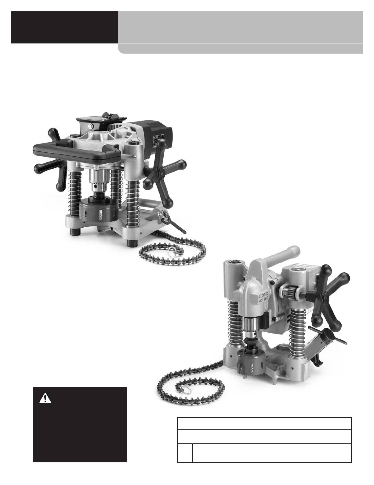
HC-450/
HC-300

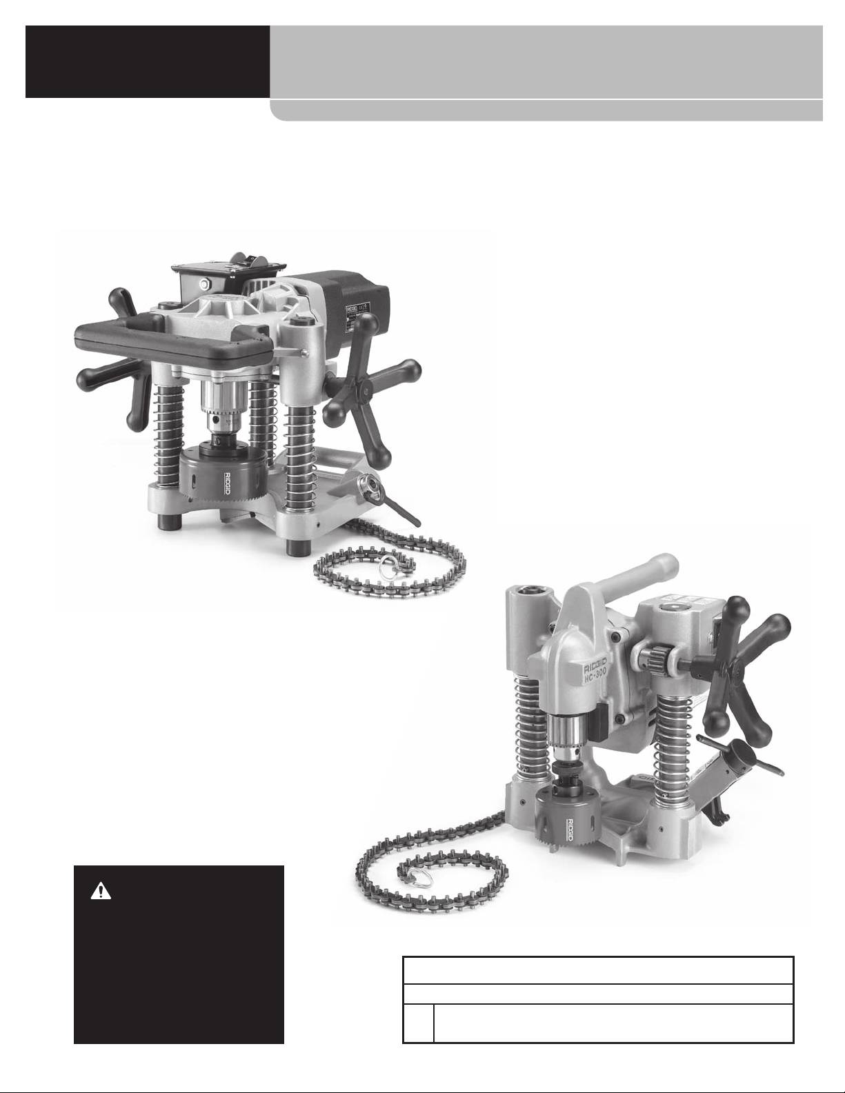
Hole Cutting Tools
HC-450/HC-300
HC-450
WARNING!
HC-300
Read this Operator’s Manual
carefully before using this
tool. Failure to understand
and follow the contents of
HC-450/HC-300 Hole Cutting Tools
this manual may result in
Record Serial Number below and retain product serial number which is located on nameplate.
electrical shock, fire and/or
Serial
serious personal injury.
No.

HC-450/HC-300 Hole Cutting Tools
Table of Contents
Recording Form For Machine Serial Number ......................................................................................................................................................1
Safety Symbols ......................................................................................................................................................................................................................3
General Safety Rules ..........................................................................................................................................................................................................3
Work Area .............................................................................................................................................................................................................................3
Electrical Safety ..................................................................................................................................................................................................................3
Personal Safety ..................................................................................................................................................................................................................4
Tool Use and Care .............................................................................................................................................................................................................4
Service ...................................................................................................................................................................................................................................4
Hole Cutter Safety Warnings .........................................................................................................................................................................................4
Model HC-450 Description, Specifications And Standard Equipment ................................................................................................5
Description ..........................................................................................................................................................................................................................5
Specifications .....................................................................................................................................................................................................................5
Standard Equipment.......................................................................................................................................................................................................5
Model HC-300 Description, Specifications And Standard Equipment ................................................................................................6
Description ..........................................................................................................................................................................................................................6
Specifications .....................................................................................................................................................................................................................6
Standard Equipment.......................................................................................................................................................................................................6
Icons .............................................................................................................................................................................................................................................6
Pre-Operation Inspection ...............................................................................................................................................................................................7
Machine And Work Area Set-Up .................................................................................................................................................................................8
Mounting The Hole Cutting Tool On The Pipe ....................................................................................................................................................8
HC-450 ...................................................................................................................................................................................................................................8
HC-300 ...................................................................................................................................................................................................................................9
Powering the Hole Cutting Tool.............................................................................................................................................................................. 10
Operating Instructions .................................................................................................................................................................................................. 11
Maintenance Instructions............................................................................................................................................................................................ 12
Cleaning ............................................................................................................................................................................................................................. 12
Lubrication ........................................................................................................................................................................................................................ 12
Changing Brushes ......................................................................................................................................................................................................... 12
Gib Screw Adjustment ................................................................................................................................................................................................ 12
Accessories ........................................................................................................................................................................................................................... 12
Machine Storage ............................................................................................................................................................................................................... 13
Service and Repair ........................................................................................................................................................................................................... 13
Disposal .................................................................................................................................................................................................................................. 13
Lifetime Warranty ........................................................................................................................................................................................... Back Cover
* Original instructions - English
2
HC-450/HC-300 Hole Cutting Tools
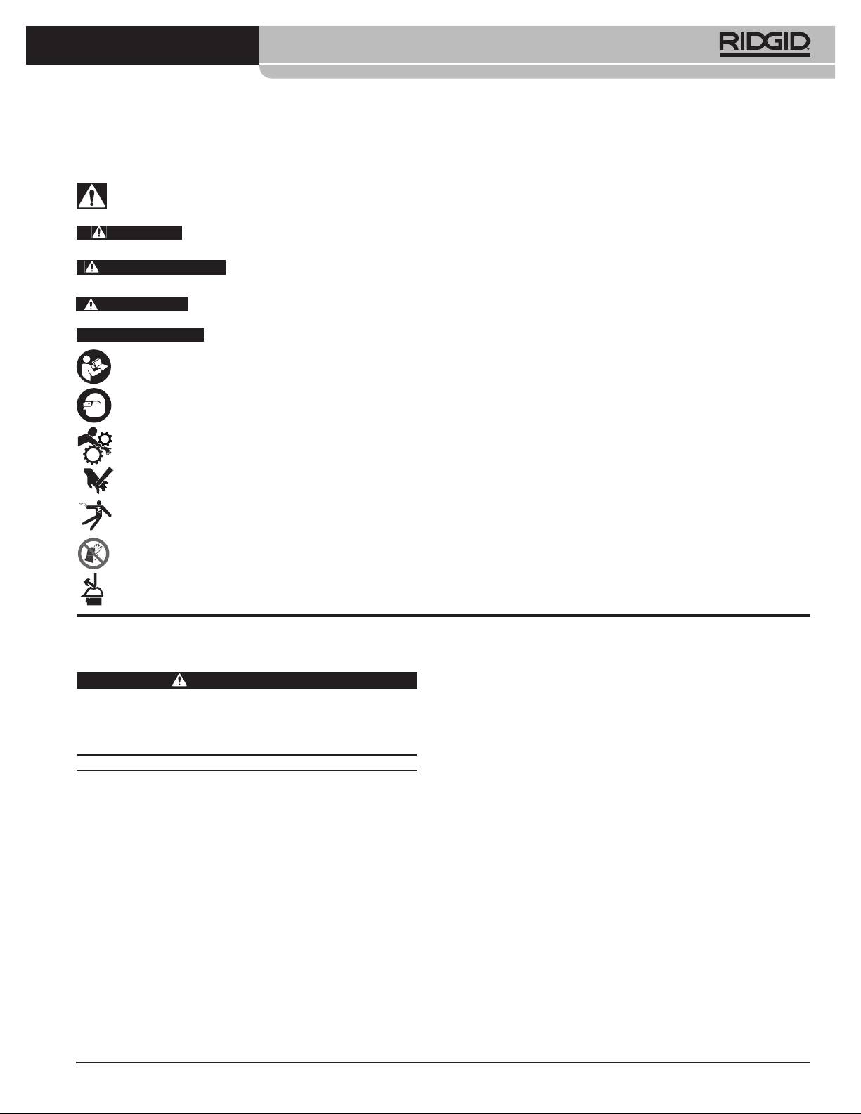
Safety Symbols
In this operator’s manual and on the product, safety symbols and signal words are used to communicate important
safety information. This section is provided to improve understanding of these signal words and symbols.
This is the safety alert symbol. It is used to alert you to potential personal injury hazards. Obey all safety messages that
follow this symbol to avoid hazardous possible injury or death.
DANGER
DANGER indicates a hazardous situation which, if not avoided, will result in death or serious injury.
WARNING
WARNING indicates a hazardous situation which, if not avoided, could result in death or serious injury.
CAUTION
CAUTION indicates a hazardous situation which, if not avoided, could result in minor or moderate injury.
NOTICE
NOTICE indicates information that relates to the protection of property.
This symbol means read the operator’s manual carefully before using the equipment. The operator’s manual contains
important information on the safe and proper operation of the equipment.
This symbol means always wear safety glasses with side shields or goggles when handling or using this equipment to
reduce the risk of eye injury.
This symbol indicates the risk of fingers, hands, clothes and other objects catching on or between gears or other rotat-
ing parts and causing crushing injuries.
This symbol indicates the risk of hands, fingers or other body parts being cut by the blade.
This symbol indicates the risk of electrical shock.
This symbol means do not wear gloves while operating this machine to reduce the risk of entanglement.
This symbol means wear a hard hat when working overhead to reduce the risk of head injury.
*
grounding prong or modify the plug in any way.
General Safety Rules
Do not use any adapter plugs. Check with a qual-
ified electrician if you are in doubt as to whether
WARNING
the outlet is properly grounded. If the tool should
Read and understand all instructions. Failure to fol-
electrically malfunction or break down, grounding
low all instructions listed below may result in elec-
provides a low resistance path to carry electricity
tric shock, fire, and/or serious injury.
away from the user.
SAVE THESE INSTRUCTIONS!
• Avoid body contact with grounded surfaces such
as pipes, radiators, ranges and refrigerators.
Work Area
There is an increased risk of electric shock if your
• Keep work area clean and well lit. Cluttered
body is grounded.
benches and dark areas invite accidents.
• Donotexposepowertoolstorainorwetcondi-
• Do not operate power tools in explosive atmo-
tions. Water entering a power tool will increase the
spheres, such as in the presence of flammable
risk of electric shock.
li quids, gases, or dust. Power tools create sparks
which may ignite the dust or fumes.
• Donotabusethecord.Neverusethecordtocar-
ry the tool or pull the plug from an outlet. Keep
• Keep bystanders, children, and visitors away
cord away from heat, oil, sharp edges or mov-
while operating a power tool. Distractions can
ing parts. Replace damaged cords immediately.
cause you to lose control.
Damaged cords increase the risk of electric shock.
Electrical Safety
• When operating a power tool outside, use an out-
door extension cord marked “W-A” or “W”. These
• Grounded tools must be plugged into an outlet
cords are rated for outdoor use and reduce the risk
properly installed and grounded in accordance
of electric shock.
with all codes and ordinances. Never remove the
* The text used in the General Safety Rule section of this manual is verbatim, as required, from the applicable UL/CSA 745 1st edition standard. This section
contains general safety practices for many different types of power tools. Not every precaution applies to every tool, and some do not apply to this tool.
3

HC-450/HC-300 Hole Cutting Tools
Personal Safety
• Maintaintoolswithcare.Keepcuttingtoolssharp
and clean. Properly maintained tools with sharp cut-
• Stay alert, watch what you are doing and use
ting edges are less likely to bind and are easier to con-
common sense when operating a power tool.
trol.
Do not use a tool while you are tired or under
the influence of drugs, alcohol or medication. A
• Check for misalignment or binding of moving
moment of inattention while operating power tools
parts, breakage of parts and any other condition
may result in serious personal injury.
that may affect the tool’s operation. If damaged,
have the tool serviced before using. Many acci-
• Dress properly. Do not wear loose clothing or
dents are caused by poorly maintained tools.
jewelry. Contain long hair. Keep your hair, cloth-
ing and gloves away from moving parts. Loose
• Useonlyaccessoriesthatarerecommendedby
clothes, jewelry or long hair can be caught in mov-
the manufacturer for your model. Accessories
ing parts.
that may be suitable for one tool, may become haz-
ardous when used on another tool.
• Avoidaccidentalstarting.BesureswitchisOFF
before plugging in. Carrying power tools with your
Service
finger on the switch or plugging in power tools that
have the switch ON invites accidents.
• Tool service must be performed only by quali-
fied repair personnel. Service or maintenance per-
• Removeadjustingkeysorwrenchesbeforeturn-
formed by unqualified personnel could result in a
ing the tool ON. A wrench or a key left attached to
risk of injury.
a rotat ing part of the power tool may result in per-
sonal injury.
• Whenservicingatool,useonlyidenticalreplace-
ment parts. Follow instructions in the Mainte-
• Donotoverreach.Keepproperfootingandbal-
nance section of this manual. Use of unauthorized
ance at all times. Proper footing and balance en-
parts or failure to follow Maintenance Instructions
ables better control of the tool in unexpected situ-
may create a risk of electrical shock or injury.
ations.
• Usesafetyequipment.Alwaysweareyeprotec-
Hole Cutter Safety Warnings
tion. Safety equipment such as dust mask, non-skid
safety shoes, hard hat, or hearing protection used
WARNING
for appropriate conditions will reduce personal inju-
This section contains important safety information
ries.
that is specific to this tool.
Tool Use and Care
Read these precautions carefully before using this
Hole Cutting Tool to reduce the risk of electrical
• Useclampsorotherpracticalwaytosecureand
shock or other serious personal injury.
support the workpiece to a stable platform. Hold-
ing the work by hand or against your body is unsta-
SAVE ALL WARNINGS AND INSTRUCTIONS
ble and may lead to loss of control.
FOR FUTURE REFERENCE!
• Donotforcethetool.Usethecorrecttoolforyour
Keep this manual with the machine for use by the opera-
application. The correct tool will do the job better
tor.
and safer at the rate for which it was designed.
• Alwayswearappropriateeyeprotection. Cutting
• Donotusethepowertooliftheswitchdoesnot
tools can break or shatter. Cutting produces chips
turn it ON and OFF. Any tool that cannot be con-
that can be thrown or fall into eyes.
trolled with the switch is dangerous and must be
• Donotwearglovesorlooseclothingwhenop-
repaired.
erating machine. Keep Sleeves and jackets but-
• Disconnecttheplugfromthepowersourcebe-
toned. Do not reach across machine. Clothing can
fore making any adjustments, changing accesso-
be caught by the machine resulting in entangle-
ries, or storing power tools. Such preventive safety
ment.
measures reduce the risk of starting the power tool
• Keep ngers and hands away from rotating
accidentally.
chuck and saw. This reduces the risk of entangle-
• Storeidletoolsoutofthereachofchildrenand
ment and cutting injuries.
other untrained persons. Tools are dangerous in
• ProperlysecuretheHoleCuttingTooltothepipe.
the hands of untrained users.
Improperly secured Hole Cutting Tools can fall and
cause striking and crushing injuries.
4

HC-450/HC-300 Hole Cutting Tools
• Donotuseforhottapping. When cutting into an
Model HC-450 Description,
existing system, the pipe must be drained and de-
Specifications And Standard
pressurized prior to cutting. This reduces the risk of
electrical shock and other serious injury.
Equipment
• Beforeusing,testtheGroundFaultCircuitInter
Description
rupter (GFCI) provided with the power cord to in-
The RIDGID® Model HC-450 Hole Cutting Tool is de-
sure it is operating properly. GFCI reduces the risk
3
signed to cut holes up to 4
/
4
” / 120 mm into steel pipe.
of electrical shock.
The multiple hole sizes allow the use of Mechanical T’s®,
• When working overhead, all personnel should
Hookers®, Vic-O-Lets™, and other fittings for branching
wear hard hats and be clear of the area below the
unpressurized pipe lines.
tool. This reduces the risk of serious injury should
5
The HC-450 has a
/
8
” / 16 mm capacity drill chuck to
objects fall.
accommodate all sizes of hole saws and hole saw ar-
• OnlyuseHoleCuttingToolstocutholesinpipe
bors. An integral motor and gear reduction optimizes
as directed in this manual. Do not use for other
performance of large diameter hole saws. The two feed
purposes or modify. Other uses or modifying this
handles allows the operator to use the Hole Cutting
tool for other purposes may increase the risk of seri-
Tool from either the left or right side. A rotating level-
ous injury.
ing vial in the base allows repeated holes to line up.
Only 13” / 32 cm high, the compact design, allows the
• Readandunderstandtheinstructionsandwarn-
HC-450 to be used in tight quarters or above installed
ings for all equipment being used before oper-
pipe close to ceilings.
ating the Hole Cutting Tool. Failure to follow all
instructions and warnings may result in property
NOTE! Mechanical T’s, Hookers, and Vic-O-Lets are reg-
damage or serious personal injury.
istered trademarks of Victaulic Tool Company.
WARNING
Some dust created by power sanding,
Specifications
sawing, grinding, drilling and other construction activi-
3
Cutting Capacity.................................... Up to 4
/
4
” / 120 mm
ties contains chemicals known to cause cancer, birth
1
defects, or other reproductive harm. Some examples of
Pipe Mounting Capacity.................... 1
/
4
” - 8” / 30 mm - 200 mm
these chemicals are:
1
5
Drill Chuck Capacity.............................
/
16
” -
/
8
” / 2 mm - 16 mm
• Lead from lead based paint
Drill Chuck Speed.................................. 110 RPM
• Crystalline silica from bricks and cement and oth-
Motor Horsepower............................... 1.2 HP / 900W
er masonry products, and
• Arsenic and chromium from chemically treated
Current Draw Rating............................ 12 Amps @ 115V
lumber
6 Amps @ 230V
Your risk from these exposures varies, depending on
12 Amps @ 100V
how often you do this type of work. To reduce your
Dimensions
exposure to these chemicals: work in a well ventilated
area, and work with approved safety equipment, such
Height........................................................ 12.62” / 32 cm
as those dust masks that are specifically designed to fil-
Length....................................................... 17” / 43 cm
ter out microscopic particles.
Width......................................................... 17” / 43 cm
The EC declaration of conformity (890-011-320.10) will
Weight....................................................... 42 lbs. / 19 kg
accompany this manual as a separate booklet when re-
quired.
Standard Equipment
If you have any question concerning this RIDGID® prod-
• Hole Cutting Tool
uct:
• Chuck Key
– Contact your local RIDGID distributor.
5
•
/
8
” / 16 mm Hole Saw Arbor w/Backing Plate and
– Visit www.RIDGID.com or www.RIDGID.eu to find
1
/
4
” / 6,3 mm Pilot Drill
your local RIDGID contact point.
– Contact RIDGID Technical Services Department at
rtctechservices@emerson.com, or in the U.S. and
Canada call (800) 519-3456.
5
HC-450/HC-300 Hole Cutting Tools
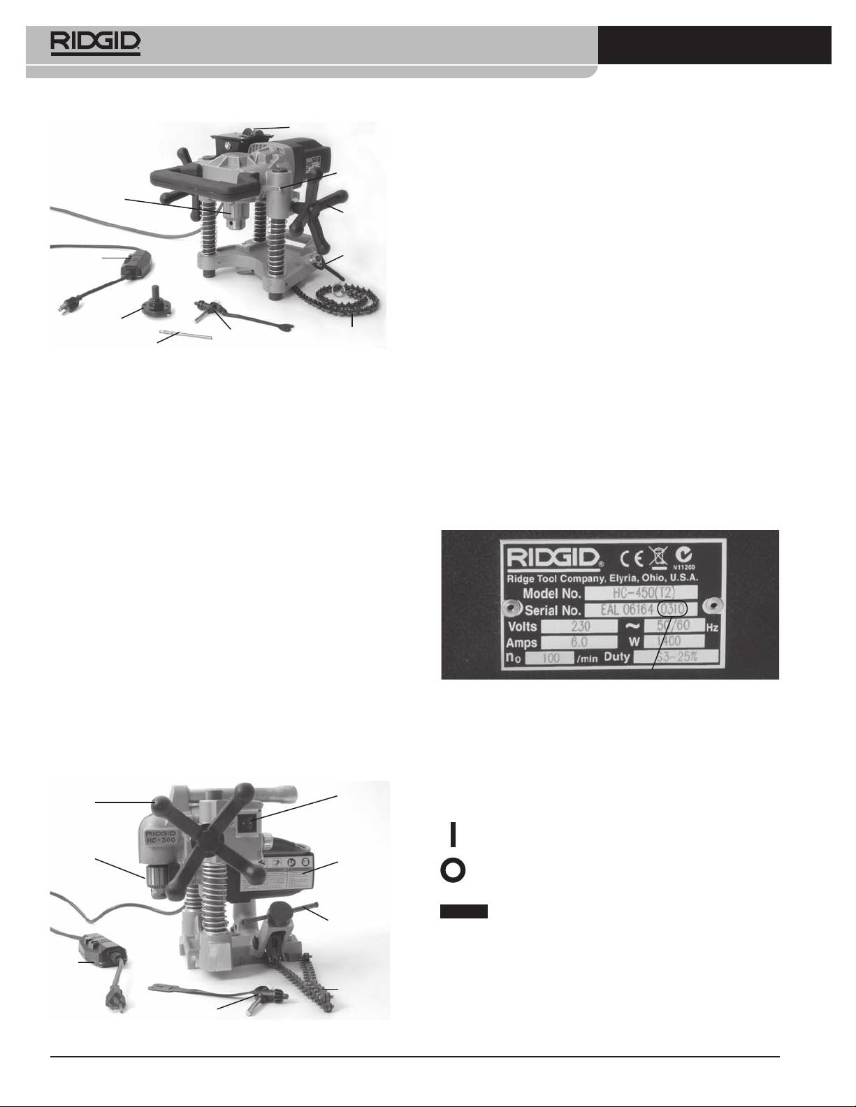
ON/OFF Switch
Specifications
Cutting Capacity............................... Up to 3” / 76 mm
Gib Screw
1
Pipe Mounting Capacity............... 1
/
4
” - 8” / 30 mm - 200 mm
Chuck
1
1
Drill Chuck Capacity........................
/
16
” -
/
2
” / 2 mm - 13 mm
Feed
Drill Chuck Speed............................. 360 RPM
Handle
Motor Horsepower........................... 1.2 HP / 900W
Swivel
GFCI
Current Draw Rating........................ 11 Amps @ 115V
Handle
5.5 Amps @ 230V /
5,5 Amps @ 230V
12 Amps @ 100V
Arbor
Dimensions
Chuck Key
Chain
Pilot Drill
Height................................................... 12.8” / 32,5 cm
Figure 1 – HC-450 with Standard Equipment
Length................................................... 11.9” / 30,2 cm
Width..................................................... 13.2” / 33,4 cm
Total Weight........................................ 31 lbs. / 14 kg
Model HC-300 Description,
Base..................................................... 10 lbs. / 4,5 kg
Specifications And Standard
Motor Assembly............................. 21 lbs. / 9,5 kg
Equipment
Standard Equipment
Description
• Hole Cutting Tool (Base and Motor Assembly)
The RIDGID® Model HC-300 Hole Cutting Tool is de-
• Chuck Key
signed to cut holes up to 3” / 76 mm diameter into steel
pipe. The multiple hole size allows the use of Mechani-
cal T’s®, Hookers®, Vic-O-Lets™, Weld-O-Let™ and other
fittings for branching unpressurized pipelines.
1
The HC-300 features a
/
2
” / 13 mm capacity chuck to
accommodate all size of holes up to 3” / 76 mm diam-
7
eter and standard hole saw arbors up to
/
16
” / 11 mm
1
Hex (
/
2
” / 13 mm chuck size). An integral motor and
gear reduction optimizes the performance and saw
Date Code
life in the capacity range. A single feed handle and ON/
Figure 3 – Machine Serial Number
OFF switch allows for easy operation. The compact
two-piece design allows the HC-300 to be used in tight
For both the HC-450 and HC-300 Hole Cutter Tool, the
quarters and difficult-to-reach locations.
serial number is located on the underside of the motor.
NOTE! Mechanical T’s, Hookers, and Vic-O-Lets are reg-
The last 4 digits indicates the month and year of the
istered trademarks of Victaulic Tool Company.
manufacture. (03 = month, 10 = year).
ON/OFF
Feed
Switch
Handle
Icons
Power ON
Warning
Chuck
Label
Power OFF
NOTICE
Selection of appropriate materials and instal-
Crank Screw
lation, joining and forming methods is the responsibil-
Assembly
ity of the system designer and/or installer. Selection of
GFIC
improper materials and methods could cause system
failure.
Chain
Stainless steel and other corrosion resistant materials
Chuck Key
can be contaminated during installation, joining and
Figure 2 – Model HC-300 with Standard Equipment
form ing. This contamination could cause corrosion and
6
HC-450/HC-300 Hole Cutting Tools
premature failure. Careful evaluation of materials and
methods for the specific service conditions, including
chemical and temperature, should be completed be-
fore any installation is attempted.
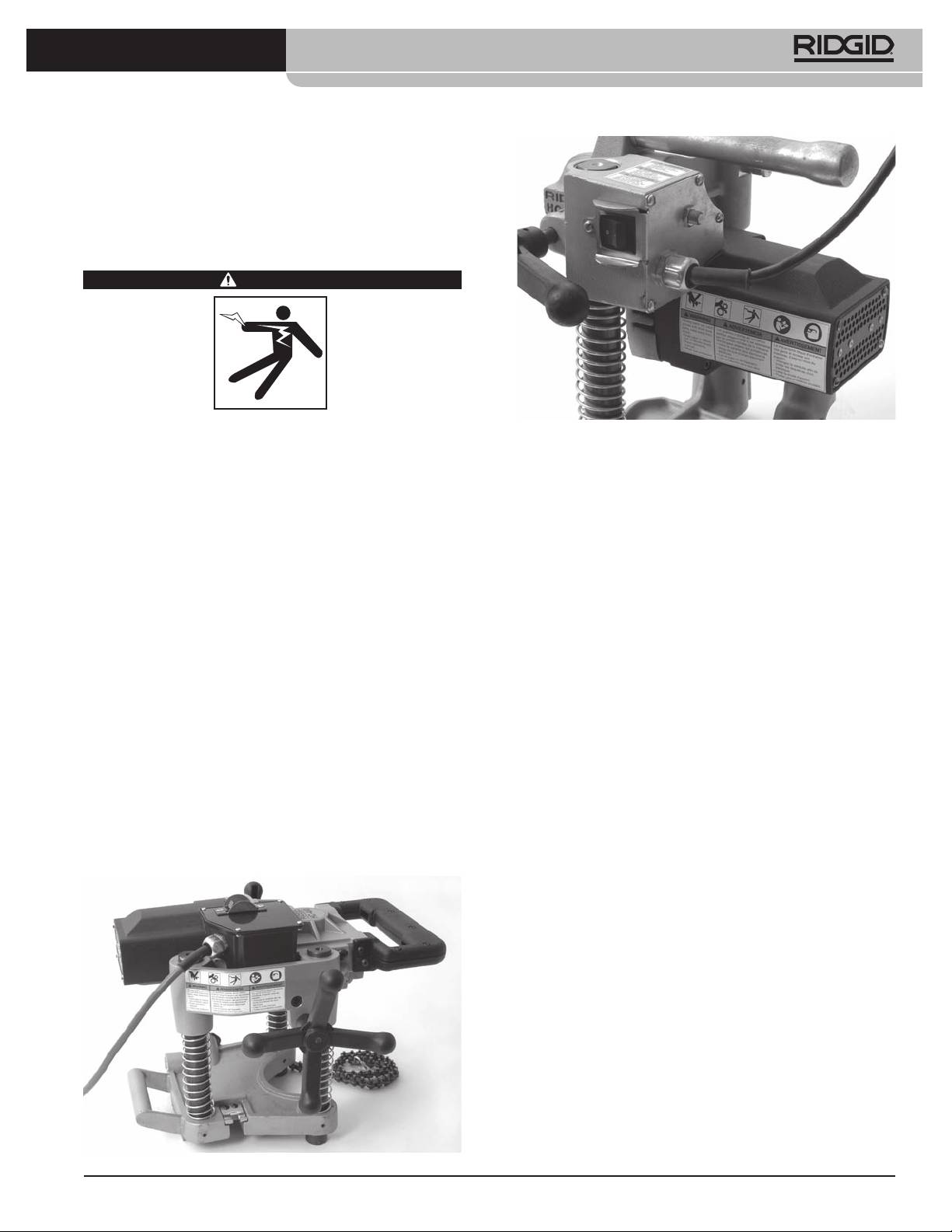
Pre-Operation Inspection
WARNING
Before each use, inspect your Hole Cutting Tool and
Figure4B–HC300WarningLabels
correct any problems to reduce the risk of serious
injury from electric shock and other causes and
prevent tool damage.
• Presence and readability of the warning labels
(see Figures 4A and 4B).
1. Make sure that the Hole Cutting Tool is unplugged
• Any other condition which may prevent safe and
and the ON/OFF switch is in the OFF position.
normal operation.
2. Clean any oil, grease or dirt from the tool, includ-
If any problems are found, do not use the hole cut-
ing the handles and controls. This aids inspection
ting tool until the problems have been repaired.
and helps prevent the tool or control from slipping
from your grip.
4. Inspect the arbor, hole saw and drills to be used with
3. Inspect the Hole Cutting Tool for the following
the Hole Cutting Tool for wear, deformation, break-
items:
age or other issues. Do not use dull or damaged cut-
ting tools. Dull or damaged cutting tools increase
• Inspect the power cord, Ground Fault Circuit Inter-
the amount of force required, produce poor quality
rupter (GFCI) and plug for damage or modifica-
cuts and increase the risk of injury.
tion.
5. With dry hands, plug the cord in. Test the GFCI in the
• Proper assembly and completeness.
electrical cord to insure that it is operating correctly.
• Broken, worn, missing, mis-aligned or binding
When the test button is pushed in, the reset button
parts. Make sure that the motor assembly moves
should pop out. Reactivate by pushing the reset
smooth ly and freely up and down the posts of
button. If the GFCI is not functioning properly, un-
the base assembly. Confirm that the chain and
plug the cord and do not use the hole cutting tool
swivel handle move freely. On the HC-300, con-
until the GFCI has been repaired.
firm that the plung er pin functions properly and
retains the motor assembly to the base assembly
6. With the Hole Cutting Tool on a stable surface check
(Figure 7).
the Hole Cutting Tool for proper operation. Keep
clear of the chuck. Move the ON/OFF switch to the
ON position. The motor should start and the chuck
turn counter clockwise viewed from the chuck end.
Inspect the tool for misalignment, binding, odd nois-
es or other unusual conditions. Move the ON/OFF
switch to the OFF position. If any issues are found,
do not use the tool until it has been repaired.
7. After the inspection is complete, with dry hands
unplug the tool.
Figure 4A – HC-450 Warning Label
7
HC-450/HC-300 Hole Cutting Tools
tapping purposes. Cutting into pressurized or
Machine And Work Area Set-Up
systems with fluids in them can cause spills, elec-
trical shock and other serious injury. Know the
WARNING
contents of the pipe and any specific hazards as-
sociated with the contents.
3. Confirm that the equipment to be used has been
pro perly inspected.
4. Select an appropriate hole saw for the work to be
performed. Make sure that the hole saw is prop-
erly assembled per its instructions and is in good
Set up the Hole Cutting Tool and work area ac-
working order. The use of a pilot drill is recom-
cording to these procedures to reduce the risk of
mended. The pilot drill should extend no more
injury from electrical shock, entanglement, crush-
3
than
/
” / 10 mm past the end of the hole saw, and
ing and other causes and prevent tool damage.
8
should be securely tightened.
Properly secure the Hole Cutting Tool to the pipe.
5. With the Hole Cutting Tool on a stable surface, in-
Improperly secured Hole Cutting Tools can slip and
stall the hole saw into the chuck. Always make sure
fall and cause striking and crushing injuries.
that the ON/OFF switch is in the OFF position and
Do not use for hot tapping. When cutting into an
the Hole Cutting Tool is unplugged before install-
existing system, the pipe must be drained and de-
ing or changing the hole saw or drill.
pressurized prior to cutting. This reduces the risk of
• Open the chuck wide enough for the shank of the
electrical shock and other serious injuries.
hole saw. If needed, the chuck key can be used
When working overhead, all personnel should wear
to open the chuck. Make sure that the shank and
hard hats and be clear of the area below. This re-
the chuck jaws are clean.
duces the risk of serious injury should equipment
• Fully insert the shank into the chuck. Make sure
or other objects fall.
that the hole saw is centered in the chuck and
1. Check work area for:
firmly tighten the chuck by hand.
• Adequate lighting.
• Use the chuck key in all three chuck holes to se-
• Flammable liquids, vapors or dust that may ig-
curely tighten the chuck onto the shank. Make
nite. If present, do not work in area until sources
sure to remove the chuck key from the chuck be-
have been identified and corrected. The hole cut-
fore turning the tool ON.
ter is not explosion proof and can cause sparks.
• Clear, level, stable, dry location for all of the equip-
Mounting The Hole Cutting Tool On
ment and operator.
The Pipe
• Properly grounded electrical outlet of the correct
Hole Cutting Tools weigh up to approximately
voltage. A three prong or GFCI outlet may not be
42 pounds / 19 kg. Use good lifting technique when
properly grounded. If in doubt, have outlet in-
placing on the pipe, do not overreach, and keep
spected by a licensed electrician.
good balance and footing at all times. Depending
• Clearpathtoelectricaloutletthatdoesnotcontain
on the circumstances, two people may be neces-
any potential sources of damage for the power cord.
sary to mount the Hole Cutting Tool onto the pipe.
2. Inspect the work to be done. Determine the pipe
Hole Cutting Tools can be used at any angle or orienta-
type and size, and clearance around the pipe. De-
tion. If cutting a hole on the side or bottom of a pipe,
termine the size and location of the hole to be cut.
it may be easier to place the Hole Cutting Tool on the
Clearly mark the cut location. If installing a fitting,
top of the pipe to fasten the chain around the pipe and
follow the fitting manufacturer’s instructions. De-
then move the Hole Cutting Tool into final position.
termine the correct equipment for the job. See the
Description and Speci fi cation sections for tool infor-
HC-450
mation.
1. Make sure the chain is hanging freely and the swiv-
Make sure that the pipe to be cut is well support-
el handle is fully loosened.
ed and stable. The pipe must be able to handle
the weight of the Hole Cutting Tool and the forces
2. Carefully lift the HC-450 Hole Cutting Tool and place
applied during cutting without moving.
with the V-shaped guides squarely on the pipe near
the location of the cut. Make sure the chain is not
If working on an existing system, make sure that
between the pipe and tool base.
the system has been depressurized and drained.
The Hole Cutting Tools are not designed for hot
8
HC-450/HC-300 Hole Cutting Tools
3. Always keep at least one hand on the Hole Cutting
Tool must be securely and squarely attached to the
Tool to stabilize and guide it. Grasp the end of the
pipe to help reduce the risk of hole saw jamming.
chain and pull it snugly around the pipe. Hook the
closest chain pin on the wear plate and firmly tight-
HC-300
en the swivel handle to hold the Hole Cutting Tool
The HC-300 can be mounted on the pipe either as a
to the pipe. (See Figure 5.)
complete unit (similar to the HC-450) or by separating
the base assembly from the tool, mounting the base to
the pipe, and then installing the motor assembly to the
base assembly.
1. With the HC-300 Hole Cutting Tool on a stable,
secure surface, pull the plunger on the back of
the left post (Figure 7) and lift the motor assem-
bly off of the base assembly.
Plunger Pin
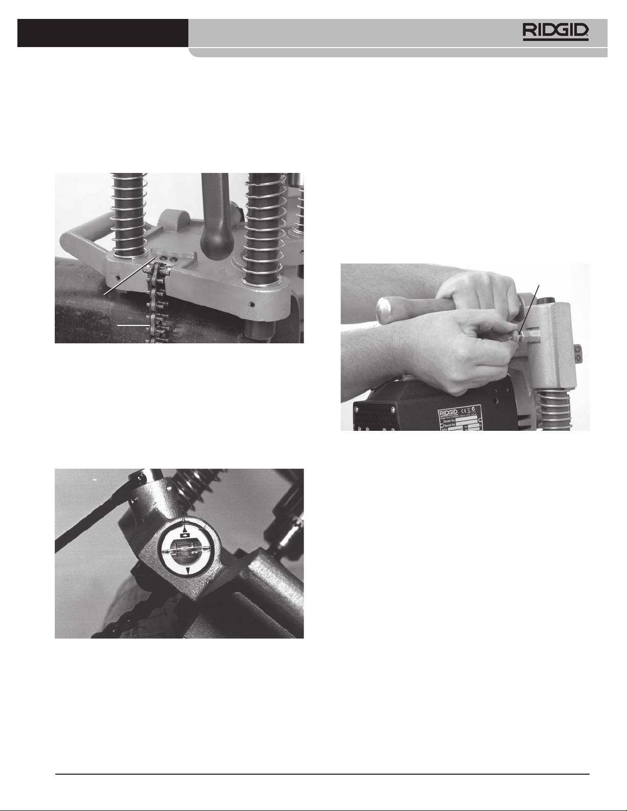
Wear Plate
Chain
Figure 5 – Hooking the HC-450 Chain
4. The base of the HC-450 Hole Cutting Tool includes
a level vial that can be used to align a series of
holes. When the Hole Cutting Tool is placed at the
desired angle, the vial can be rotated to the level
position, and subsequent holes can be made at the
same angle by leveling the Hole Cutting Tool with
Figure7–SeparatingtheBaseandMotorAssemblies
the vial. (See Figure 6.)
2. Make sure the chain is hanging freely and the swiv-
el handle is fully loosened on the base assembly.
3. Place the base assembly with the V-shaped guides
squarely on the pipe near the location of the cut.
Make sure the chain is not between the pipe and
tool base.
4. Always keep at least one hand on the base assem-
bly to stabilize and guide it. Grasp the end of the
chain and pull it snugly around the pipe. As you
pull on the chain, a spring is compressed at the
attachment end of the chain. Hook the closest
chain pin on the chain hook – the spring tension
will help keep the chain engaged with the chain
hook. Firmly tighten the crank screw assembly to
hold the base assembly to the pipe. (See Figure 8.)
Figure 6 – HC-450 Hole Cutting Tool Level Vial
5. With one hand on the Hole Cutting Tool to stabilize
and guide it, slightly loosen the swivel handle to al-
low final positioning of the tool. Align the pilot drill
with the desired cut location, and firmly tighten the
swivel handle. Do not remove your hands from the
Hole Cutting Tool until you have confirmed that it
is securely attached to the pipe. The Hole Cutting
9

HC-450/HC-300 Hole Cutting Tools
Figure 10 – HC-300 Leveling
Figure 8 – Hooking the Chain
7. With one hand on the Hole Cutting Tool to stabilize
5. Carefully lift the motor assembly and align the post
and guide it, slightly loosen the crank screw assem-
openings in the motor assembly with the posts of
bly to allow final positioning of the tool. Align the
the base assembly. Press the motor assembly on
pilot drill with the desired cut location, and firmly
until the plunger engages the post to retain the
tighten the crank screw assembly. Do not remove
motor assembly to the base. Confirm that the mo-
your hands from the Hole Cutting Tool until you
tor assembly is securely attached to the base. (See
have confirmed that it is securely attached to the
Figure 9.)
pipe. The Hole Cutting Tool must be securely and
6. The base of the HC-300 includes several machined
squarely attached to the pipe to help reduce the
flats for use with levels for hole alignment. (See Fig-
risk of hole saw jamming.
ure 10.)
To mount the HC-300 on the pipe as a complete unit,
follow the steps indicated in the HC-450 section, using
the information in the HC-300 section on chain hook-
ing and alignment.
Powering the Hole Cutting Tool
1. Confirm that the ON/OFF switch is in the OFF posi-
tion.
2. Makes sure that the power cord is routed out the
back of the tool away from the chuck and work
area. Run the cord along the clear path to the out-
let, and with dry hand plug in. Keep all connections
dry and off the ground. If the power cord is not long
enough, use an extension cord that:
• Is in good condition.
• Has a three prong plug similar to that on the
tool.
• Is rated for outdoor use and contains a “W” or
“W-A” in the cord designation (i.e. SOW), or com-
plies with H05VV-F, H07VV-F, H05RN-F, H07RN-F
types or IEC type design (60227 IEC 53, 60245 IEC
57).
2
• Has sufficient wire size (16 AWG / 1,5 mm
for 50’ /
2
15,2 m or less, 14 AWG / 2,5 mm
for 50’ – 100’ /
15,2 m – 30,5 m long). Undersized wires can over-
heat, melting the insulation or causing a fire or
other damage.
Figure 9 – Attaching the HC-300 Motor Assembly to the
BaseAssembly
10

HC-450/HC-300 Hole Cutting Tools
When using an extension cord, the GFCI on the
4. Place both hands on the hand wheel and advance
Hole Cutting Tool does not protect the extension
the pilot drill into contact with the pipe. Apply firm
cord. If the outlet is not GFCI protected, it is ad-
pressure, and start drilling the pilot hole. Do not
visable to use a plug in type GFCI between the
force the pilot drill/hole saw. This can overload the
outlet and the extension cord to reduce the risk
hole saw and the tool motor and cause premature
of shock if there is a fault in the extension cord.
failure.
Operating Instructions
WARNING
Always wear appropriate eye protection. Cutting
tools can break or shatter. Cutting produces chips
that can be thrown or fall into eyes.
Figure 11 – Operating the Hole Cutting Tool
Do not use for hot tapping. When cutting into an
existing system, the pipe must be drained and de-
pressurized prior to cutting. This reduces the risk of
Once the hole saw is in contact with the pipe, con-
electrical shock and other serious injury.
tinue to apply firm pressure. Depending on the
Do not wear gloves or loose clothing when operat-
size and wall thickness of the pipe and the size of
ing machine. Keep Sleeves and jackets buttoned. Do
the hole being cut, the hole saw may need to be
not reach across machine. Clothing can be caught
retracted slightly at times for chip removal.
by the machine resulting in entanglement.
If needed, the Hole Cutting Tool can be shut off and
Keep fingers and hands away from rotating chuck
a small amount of appropriate cutting lubricant
and saw. This reduces the risk of entanglement and
applied to the work piece. Do not apply lubricant
cutting injuries.
while the tool is running, this increases the risk of
entanglement. Take appropriate steps to prevent
Follow operating instructions to reduce the risk of
the lubricant from dripping or being thrown dur-
injury from electrical shock entanglement, crush-
ing use.
ing and other causes and prevent Hole Cutter dam-
age.
As the hole saw moves through the pipe and as the
1. Confirm that the Hole Cutting Tool and work area
cut is completed, there will be an interrupted cut
are properly set up and that the work area is free of
at times. Decrease pressure as this occurs to help
bystanders and other distractions.
prevent jamming of the hole saw.
2. Assume a proper operating position that will al-
5. Once the hole is complete, retract the hole saw
low:
from the pipe and turn the ON/OFF switch OFF.
• Control of the Hole Cutting Tool, including the ON/
6. Reverse the mounting procedure to remove the
OFF switch and the feed handle. On the HC-300
Hole Cutting Tool from the pipe. Make sure you
you must be on the same side as the switch and
have secure grip on the Hole Cutting Tool prior to
the feed handle. Do not turn the tool ON yet.
loosening the chain or pulling the plunger on the
HC-300.
• Good balance. Be sure that you do not have to
over reach.
7. If the pipe slug needs to be removed from the hole
saw, always make sure that the ON/OFF switch is in
3. Move the ON/OFF switch to the ON position. Ob-
the OFF position and the Hole Cutting Tool is un-
serve the rotation of the hole saw and pilot drill,
plugged before removing. Remove the slug with
making sure it is running straight and true. If they
care, the slug may be hot and edges can be sharp.
wobble, or any other issues are noted, move the
switch to OFF and unplug tool, fix any issues prior
to using. Keep fingers, hands and clothes away
from the turning chuck to help reduce the risk of
entanglement.
11
HC-450/HC-300 Hole Cutting Tools
4. Depress the brush into the holder and insert into
Maintenance Instructions
the motor housing. Inspect to make sure insula-
tor sheets are properly positioned between brush
WARNING
holder and housing. Attach the connector and re-
Make sure that the ON/OFF switch is in the OFF po-
place the motor cover.
sition and the tool is unplugged before performing
any maintenance or making any adjustments.
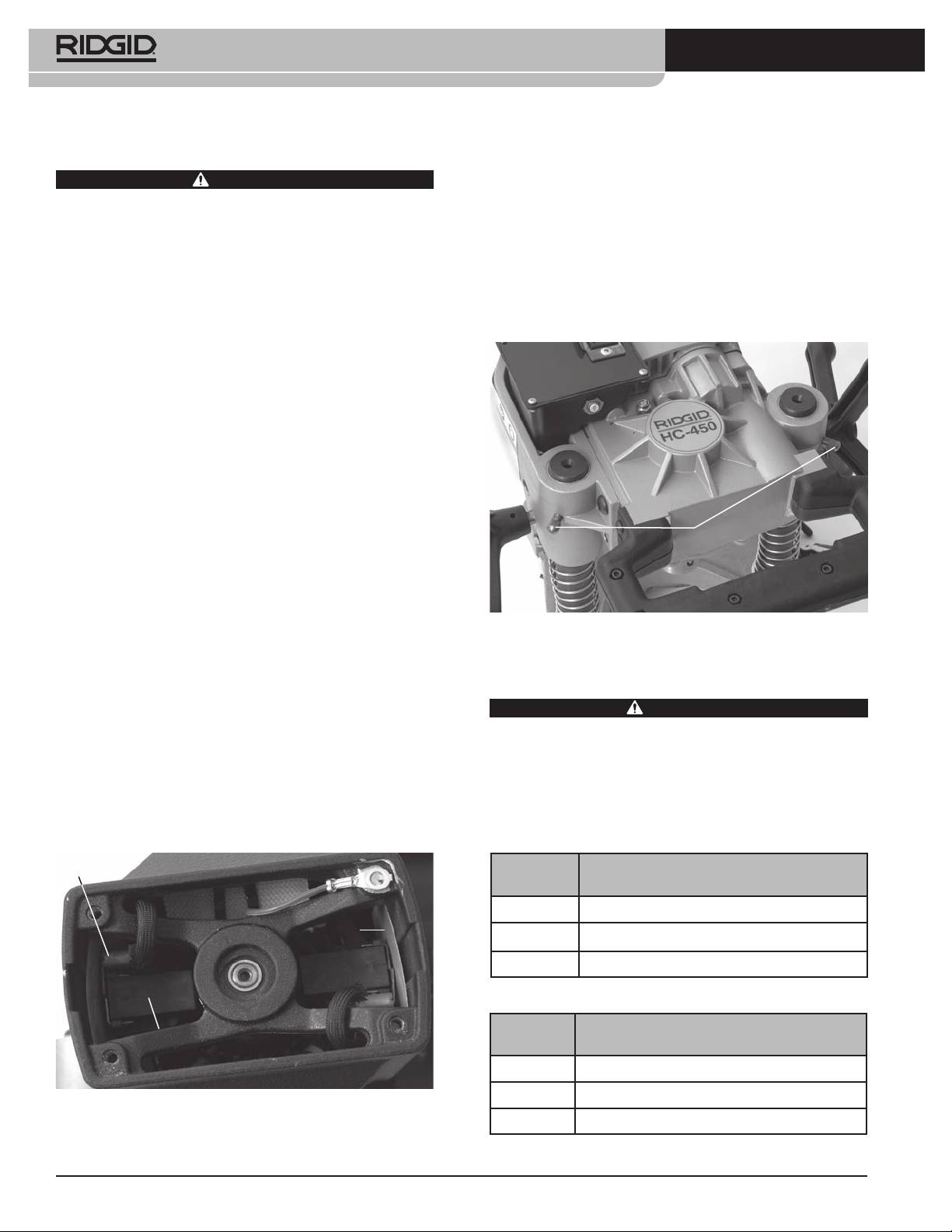
Gib Screw Adjustment
Maintain tool according to these procedures to re-
Gib screws are provided on the HC-450 to allow ad-
duce the risk of injury from electrical shock, entan-
justment of the drag between the base and motor as-
glement and other causes.
semblies. Tighten or loosen the Gib screws to adjust as
Cleaning
desired. (See Figure 13.)
After each use, wipe any chips or oil off with a soft, clean,
damp cloth, especially areas of relative motion such as
the posts. Clean any dust and debris from the motor
vents.
Lubrication
The Hole Cutting Tools gearboxes are designed as sealed
systems, and should not require any additional grease
unless significant leakage has occurred. In those cases,
the tools should be returned to a service center.
Gib Screws
Do not lubricate the bearings that ride on the posts. The
bearings are not designed to be used with lubricants,
and lubricants will hold dirt and debris that could dam-
age the bearings.
Figure 13 – Adjusting Gib Screws
As needed, the chain and screw assemblies can be lu-
bricated with a light lubricating oil. Wipe any excess oil
from exposed surfaces.
Accessories
Changing Brushes
WARNING
Check motor brushes every six months and replace
To reduce the risk of serious injury, only use acces-
1
when worn to less than
/
2
” / 1,3 cm.
sories specifically designed and recommended for
use with the RIDGID Hole Cutting Tools, such as
1. Remove four screws holding motor cover, remove
those listed below. Other Accessories suitable for
cover.
use with other tools may be hazardous when used
2. Using a pair of pliers, pull the motor brushes straight
with the RIDGID Hole Cutting Tools.
out. Detach the connector. (See Figure 12.)
Model HC-300
Connector
Catalog
No. Description
16671 R2S Solid Shank Arbor
Insulator
Sheet
84427 HC-450/HC-300 Carrying Case
77017 Chuck Key
Model HC-450
Catalog
Brush
No. Description
84427 HC-450 Carry Case
5
59502 R4
/
8
” / 16 mm Arbor only for Hole Saws
Figure12–BrushPlacementMotorCoverRemoved
59132 Chuck Key
3. Inspect the commutator for wear. If excessively
worn, have tool serviced.
See RIDGID catalog for listing of Hole Saws.
12
HC-450/HC-300 Hole Cutting Tools
Machine Storage
Disposal
WARNING
The Hole Cutting Tool must be kept in-
Parts of the Hole Cutting Tool contain valuable materi-
doors or well covered in rainy weather. Store the ma-
als and can be recycled. There are companies that spe-
chine in a locked area that is out of reach of children
cialize in recycling that may be found locally. Dispose
and people unfamiliar with hole cutting tool. This ma-
of the com ponents in compliance with all applicable
chine can cause serious injury in the hands of untrained
regulations. Contact your local waste management au-
users.
thority for more information.
For EC Countries: Do not dispose of electri-
Service and Repair
cal equipment with household waste!
According to the European Guideline 2002/ -
WARNING
96/ EC for Waste Electrical and Electronic
Improper service or repair can make machine un-
Equipment and its implemen tation into na-
safe to operate.
tional legislation, electrical equipment that
The “Maintenance Instructions” will take care of most
is no longer usable must be collected separately and
of the service needs of this machine. Any problems not
disposed of in an environmentally correct manner.
addressed by this section should only be handled by
an authorized RIDGID service technician.
Tool should be taken to a RIDGID Independent Author-
ized Service Center or returned to the factory.
For information on your nearest RIDGID Independent
Service Center or any service or repair questions:
• Contact your local RIDGID distributor.
• Visit www.RIDGID.com or www.RIDGID.eu to find
your local RIDGID contact point.
• Contact RIDGID Technical Services Department at
rtctechservices@emerson.com, or in the U.S. and
Canada call (800) 519-3456.
13

HC-450/HC-300 Hole Cutting Tools
14
Scies à cloche
HC-450/HC-300
HC-450
HC-300
AVERTISSEMENT
Lisez ce manuel soigneusement
avant d’utiliser l’appareil.
L’incompréhension ou le non re-
Scies à cloche HC-450 et HC-300
spect des consignes ci-devant pour-
Notez ci-dessous le numéro de série indiqué sur la plaque signalétique de l’appareil pour future
référence.
rait entraîner des chocs
électriques, des incendies et/ou de
Nº de
graves blessures corporelles.
série

Scies à cloche HC-450 et HC-300
Table des matières
Fiche dʼenregistrement du numéro de série de lʼappareil .......................................................................................15
Symboles de sécurité..................................................................................................................................................17
Consignes générales de sécurité
Sécurité des lieux ......................................................................................................................................................17
Sécurité électrique.....................................................................................................................................................17
Sécurité individuelle ..................................................................................................................................................18
Utilisation et entretien de lʼappareil ...........................................................................................................................18
Service après-vente ..................................................................................................................................................18
Consignes de sécurité visant les scies à cloche .....................................................................................................19
HC-450 : Description, caractéristiques techniques et équipements de base
Description ................................................................................................................................................................19
Caractéristiques ........................................................................................................................................................20
Equipements de base................................................................................................................................................20
HC-300 : Description, caractéristiques techniques et équipements de base
Description ................................................................................................................................................................20
Caractéristiques ........................................................................................................................................................20
Equipements de base................................................................................................................................................21
Icônes ...........................................................................................................................................................................21
Inspection préalable de lʼappareil..............................................................................................................................21
Préparation de lʼappareil et du chantier ....................................................................................................................22
Montage de la scie à cloche sur le tuyau
HC-450 ......................................................................................................................................................................23
HC-300 ......................................................................................................................................................................24
Entraînement de la scie à cloche ..............................................................................................................................25
Consignes dʼutilisation ...............................................................................................................................................25
Consignes dʼentretien
Nettoyage ..................................................................................................................................................................27
Lubrification ...............................................................................................................................................................27
Remplacement des balais .........................................................................................................................................27
Réglage des vis de calage ........................................................................................................................................27
Accessoires .................................................................................................................................................................27
Stockage de lʼappareil.................................................................................................................................................27
Révisions et réparations.............................................................................................................................................28
Recyclage.....................................................................................................................................................................28
Garantie à vie............................................................................................................................................Page de garde
*Traduction de la notice originale
16
Scies à cloche HC-450 et HC-300
Symboles de sécurité
Des symboles et mots clés spécifiques, utilisés à la fois dans ce mode dʼemploi et sur lʼappareil lui-même, servent à signaler
dʼimportants risques de sécurité. Ce qui suit permettra de mieux comprendre la signification de ces mots clés et symboles.
Ce symbole sert à vous avertir aux dangers physiques potentiels. Le respect des consignes qui le suivent vous permettra dʼéviter
les risques de blessures graves ou mortelles.
Le terme DANGER signifie une situation dangereuse potentielle qui, faute dʼêtre évitée, provoquerait la mort ou de
DANGER
graves blessures corporelles.
Le terme AVERTISSEMENT signifie une situation dangereuse potentielle qui, faute dʼêtre évitée, serait sus-
AVERTISSEMENT
ceptible dʼentraîner la mort ou de graves blessures corporelles.
Le terme ATTENTION signifie une situation dangereuse potentielle qui, faute dʼêtre évitée, serait susceptible
ATTENTION
dʼentraîner des blessures corporelles légères ou modérées.
AVIS IMPORTANT
Le terme AVIS IMPORTANT signifie des informations concernant la protection des biens.
Ce symbole indique la nécessité de lire le manuel soigneusement avant dʼutiliser le matériel. Le mode dʼemploi renferme
dʼimportantes informations concernant la sécurité dʼutilisation du matériel.
Ce symbole indique le port obligatoire de lunettes de sécurité intégrales lors de la manipulation ou utilisation du matériel.
Ce symbole indique un risque dʼentraînement des doigts, des mains, des vêtements ou autres objets dans le mécanisme, et
les risques dʼécrasement éventuels.
Ce symbole signale un risque de coupure des doigts, des mains et autres membres par la lame de lʼappareil.
Ce symbole signale un risque de choc électrique.
Ce symbole veut dire quʼil ne faut pas porter de gants lors de lʼutilisation de lʼappareil afin de limiter les risques dʼentraînement.
Ce symbole impose le port du casque lors des travaux en surélévation.
*
tions risquent de vous faire perdre le contrôle de
Consignes générales de sécurité
lʼappareil.
AVERTISSEMENT
Familiarisez-vous avec lʼensemble du mode dʼemploi. Le
Sécurité électrique
non-respect des consignes dʼutilisation et de sécurité ci-
• Tout appareil équipé dʼune mise à la terre doit être
après augmenterait les risques de choc électrique,
branché sur une prise de courant avec terre, cor-
dʼincendie et/ou de grave blessure corporelle.
rectement installée et raccordée selon les normes
CONSERVEZ CES INSTRUCTIONS !
en vigueur. Ne jamais éliminer la broche de mise à
la terre ou modifier la fiche dʼune manière quel-
Sécurité des lieux
conque. En cas de doute sur la qualité de mise à la
• Assurez-vous de la propreté et du bon éclairage
terre de la prise, consultez un électricien. La mise à
des lieux. Les zones encombrées ou mal éclairées
la terre permet dʼéloigner le courant de lʼutilisateur en
sont une invitation aux accidents.
cas dʼanomalie électrique de lʼappareil.
• Nʼutilisez pas ce matériel en présence de matières
• Evitez tout contact physique avec les objets re-
explosives telles que liquides, gaz ou poussières
liés à la terre tels que canalisations, radiateurs,
combustibles. Les appareils électriques produisent
cuisinières et réfrigérateurs. Tout contact avec la
des étincelles susceptibles dʼenflammer les poussières
terre augmenterait les risques de choc électrique.
et émanations combustibles.
• Nʼexposez pas lʼappareil à la pluie ou aux intem-
• Eloignez les enfants et les curieux lors de
péries. Toute pénétration dʼeau à lʼintérieur de ce
lʼutilisation dʼun appareil électrique. Les distrac-
matériel augmenterait les risques de choc électrique.
* Le texte utilisé dans la section Consignes générales de sécurité est conforme au chapitre applicable de la première édition de la norme ULCSA 745. Ce chapitre
renferme des consignes de sécurité générales applicables à de nombreux types dʼappareils électriques. Toutes les consignes ne sʼappliquent pas forcément
à lʼensemble de ces appareils, et certaines dʼentre elles ne sʼappliquent pas à lʼappareil ci-présent.
17

Scies à cloche HC-450 et HC-300
• Ne maltraitez pas le cordon dʼalimentation de
créerait une situation dʼinstabilité susceptible dʼentraîner
lʼappareil. Ne jamais utiliser le cordon pour trans-
la perte de contrôle de lʼouvrage.
porter, tirer ou débrancher lʼappareil. Éloignez le
• Ne forcez pas les outils. Prévoyez lʼoutil appro-
cordon des sources de chaleur, des matières
prié en fonction des travaux envisagés. Le matériel
huileuses, des objets tranchants et des mécan-
approprié fera le travail plus efficacement et avec un
ismes. Les cordons dʼalimentation endommagés ou
plus grand niveau de sécurité lorsquʼil tourne au régime
tortillés augmentent les risques de choc électrique.
prévu.
• Lors des travaux à lʼextérieur, prévoyez une ral-
• Nʼutilisez pas de matériel électrique dont
longe électrique adaptée et portant la désignation
lʼinterrupteur ne contrôle pas la mise en marche
« W-A » ou « W ». Les rallonges prévues pour
ou lʼarrêt. Tout appareil électrique qui ne peut pas être
lʼextérieur limitent les risques de choc électrique.
contrôlé par son interrupteur est dangereux et doit être
réparé.
Sécurité individuelle
• Débranchez lʼappareil avant son réglage, change-
• Soyez attentif, faites attention à ce que vous faites
ment dʼaccessoires ou stockage. De telles mesures
et faites preuve de bon sens. Nʼutilisez pas ce
préventives limiteront les risques de démarrage acci-
matériel lorsque vous êtes sous lʼinfluence de
dentel de lʼappareil.
drogues, de lʼalcool ou de médicaments. Lors de
lʼutilisation de ce type dʼappareil, un instant dʼinattention
• Rangez les outils non utilisés hors de la portée des
risque dʼentraîner de graves lésions corporelles.
enfants et des individus qui nʼont pas été famil-
iarisés avec ce type de matériel ou son mode
• Habillez-vous de manière appropriée. Ne portez
dʼemploi. Ce type dʼoutil peut sʼavérer dangereux sʼil
pas de vêtements trop amples ou de bijoux.
tombe entre les mains dʼutilisateurs non initiés.
Contenez les cheveux longs. Eloignez vos cheveux,
vos vêtements et vos gants des mécanismes. Les
• Veillez à lʼentretien quotidien des outils, notam-
vêtements amples, les bijoux et les cheveux longs
ment en ce qui concerne leur affûtage et leur pro-
risquent dʼêtre entraînés dans le mécanisme.
preté. Des outils correctement entretenus et affûtés
seront plus faciles à contrôler et moins susceptibles de
• Evitez les démarrages accidentels. Assurez-vous
se gripper.
que lʼinterrupteur de lʼappareil nʼest pas en position
de marche avant de le brancher. Porter un appareil
• Examinez lʼappareil pour signes de mauvais aligne-
électrique avec un doigt sur son interrupteur ou avoir
ment, détérioration ou grippage de ses mécan-
lʼinterrupteur en position de marche lors de son branche-
ismes, voire toute autre anomalie susceptible de
ment est une invitation aux accidents.
nuire à son bon fonctionnement. Le cas échéant, il
sera nécessaire de faire réparer lʼappareil avant de
• Retirez dʼéventuelles clés de réglage avant de met-
vous en servir. De nombreux accidents sont provoqués
tre lʼappareil en marche. Une clé laissée sur le mé-
par des appareils électriques mal entretenus.
canisme de lʼappareil pourrait provoquer des blessures
corporelles.
• Utilisez exclusivement les accessoires prévus par
le fabricant pour votre type dʼappareil particulier.
• Ne vous mettez pas en porte-à-faux. Maintenez
Toute tentative dʼadaptation dʼaccessoires prévus pour
une bonne position de travail et un bon équilibre à
dʼautres types dʼappareil pourrait sʼavérer dangereuse.
tout moment. Cela vous permettra de mieux con-
trôler lʼoutil en cas dʼimprévu.
Révisions
• Prévoyez les équipements de protection individuelle
• La révision de cet appareil doit être confiée à un ré-
nécessaires. Portez systématiquement une pro-
parateur agréé. Toute intervention effectuée par du
tection oculaire. Le port dʼun masque à poussière, de
personnel non qualifié augmenterait les risques de
chaussures de sécurité antidérapantes, dʼun casque de
blessure corporelle.
chantier ou de protecteurs dʼoreilles sʼimpose lorsque les
conditions lʼexigent.
• Nʼutilisez que des pièces de rechanges dʼorigine
lors de la réparation de lʼappareil. Respectez les
Utilisation et entretien de l’appareil
consignes de la section Entretien de cette notice.
• Servez-vous de serre-joints ou dʼautres moyens
Lʼutilisation de pièces ou de méthodes non prévues
dʼarrimer lʼouvrage sur une plate-forme stable. Le
augmenterait les risques de choc électrique et autres
fait de tenir un ouvrage à la main ou contre son corps
blessures.
18
