chiliGREEN P5G41T-M LX2: инструкция
Раздел: Бытовая, кухонная техника, электроника и оборудование
Тип: Компьютер
Инструкция к Компьютеру chiliGREEN P5G41T-M LX2
Index
1. English .................................................................................1
2. TürkçeTürkçe ................................................................................45
3.
Български
.............................................................................89
4. Česky ...............................................................................131
5. Magyar .............................................................................173
6. Bahasa Indonesia ............................................................215
7. Italiano..............................................................................257
8.
한국어
..............................................................................301
9. Polski ................................................................................343
10. Português .........................................................................385
11. Română............................................................................427
12.
Русский
..............................................................................469
13. Srpski ...............................................................................511
14. Español ............................................................................553
15.
ไทย
...................................................................................595
16. TiếngViệt .........................................................................637
17. ................................................................................676

Motherboard
installation guide
Motherboard

E4973
Second Edition V2
August 2009
Copyright © 2009 ASUSTeK COMPUTER INC. All Rights Reserved.
No part of this manual, including the products and software described in it, may be reproduced,
transmitted, transcribed, stored in a retrieval system, or translated into any language in any form or by any
means, except documentation kept by the purchaser for backup purposes, without the express written
permission of ASUSTeK COMPUTER INC. (“ASUS”).
Product warranty or service will not be extended if: (1) the product is repaired, modied or altered, unless
such repair, modication of alteration is authorized in writing by ASUS; or (2) the serial number of the
product is defaced or missing.
ASUS PROVIDES THIS MANUAL “AS IS” WITHOUT WARRANTY OF ANY KIND, EITHER EXPRESS
OR IMPLIED, INCLUDING BUT NOT LIMITED TO THE IMPLIED WARRANTIES OR CONDITIONS OF
MERCHANTABILITY OR FITNESS FOR A PARTICULAR PURPOSE. IN NO EVENT SHALL ASUS, ITS
DIRECTORS, OFFICERS, EMPLOYEES OR AGENTS BE LIABLE FOR ANY INDIRECT, SPECIAL,
INCIDENTAL, OR CONSEQUENTIAL DAMAGES (INCLUDING DAMAGES FOR LOSS OF PROFITS,
LOSS OF BUSINESS, LOSS OF USE OR DATA, INTERRUPTION OF BUSINESS AND THE LIKE),
EVEN IF ASUS HAS BEEN ADVISED OF THE POSSIBILITY OF SUCH DAMAGES ARISING FROM ANY
DEFECT OR ERROR IN THIS MANUAL OR PRODUCT.
SPECIFICATIONS AND INFORMATION CONTAINED IN THIS MANUAL ARE FURNISHED FOR
INFORMATIONAL USE ONLY, AND ARE SUBJECT TO CHANGE AT ANY TIME WITHOUT NOTICE,
AND SHOULD NOT BE CONSTRUED AS A COMMITMENT BY ASUS. ASUS ASSUMES NO
RESPONSIBILITY OR LIABILITY FOR ANY ERRORS OR INACCURACIES THAT MAY APPEAR IN THIS
MANUAL, INCLUDING THE PRODUCTS AND SOFTWARE DESCRIBED IN IT.
Products and corporate names appearing in this manual may or may not be registered trademarks or
copyrights of their respective companies, and are used only for identication or explanation and to the
owners’ benet, without intent to infringe.
2

Safety information
Electrical safety
•
To prevent electrical shock hazard, disconnect the power cable from the
electrical outlet before relocating the system.
•
When adding or removing devices to or from the system, ensure that the power
cables for the devices are unplugged before the signal cables are connected. If
possible, disconnect all power cables from the existing system before you add
a device.
•
Before connecting or removing signal cables from the motherboard, ensure
that all power cables are unplugged.
•
Seek professional assistance before using an adpater or extension cord.
These devices could interrupt the grounding circuit.
•
Ensure that your power supply is set to the correct voltage in your area. If you
are not sure about the voltage of the electrical outlet you are using, contact
your local power company.
•
If the power supply is broken, do not try to x it by yourself. Contact a qualied
service technician or your retailer.
Operation safety
•
Before installing the motherboard and adding devices on it, carefully read all
the manuals that came with the package.
•
Before using the product, ensure all cables are correctly connected and the
power cables are not damaged. If you detect any damage, contact your dealer
immediately.
•
To avoid short circuits, keep paper clips, screws, and staples away from
connectors, slots, sockets, and circuitry.
•
Avoid dust, humidity, and temperature extremes. Do not place the product in
any area where it may become wet.
•
Place the product on a stable surface.
•
If you encounter technical problems with the product, contact a qualied
service technician or your retailer.
3

4
Chapter 1: Quick Start
1.1 Installing the CPU
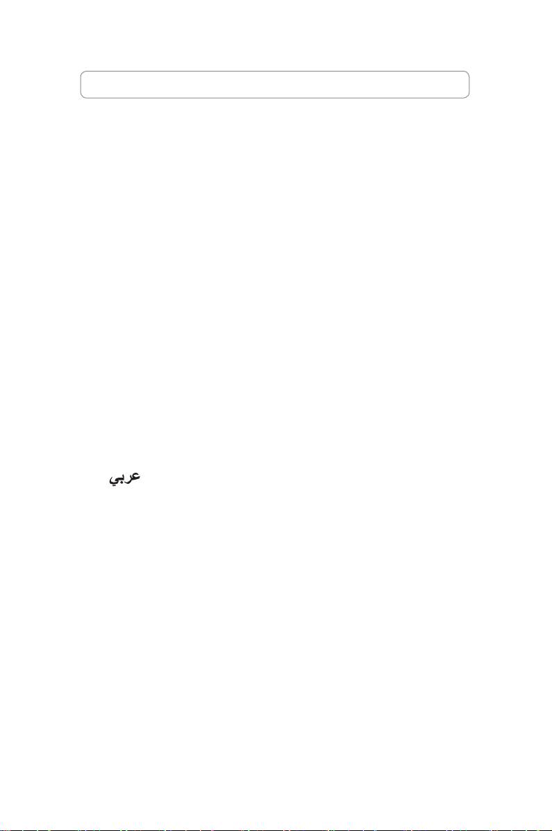
1.1.1 Intel LGA775 Socket
1. Locate the CPU socket on the
2. Release the load lever from the
motherboard.
retention tab and lift the load plate.
Then push the PnP cap from the
load plate window to remove
To prevent damage to the socket
pins, do not remove the PnP cap
Pick and Place Cap (PnP Cap)
unless you are installing a CPU.
4. Ensure that the gold triangle is
3. Position the CPU over the socket.
on the bottom‑left corner of the
socket.
ASUS Motherboard installation guide 5
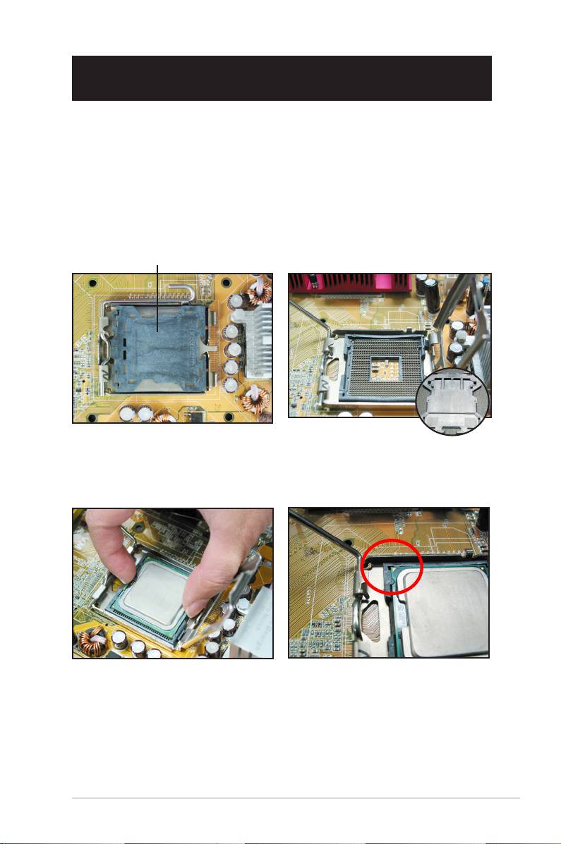
5. Fit the socket alignment key into the CPU notch.
6. Close the load plate, then push the load lever until it snaps into the retention
tab.
The CPU ts in only one correct
orientation. DO NOT force the
CPU into the socket to prevent
bending the connectors on the
socket and damaging the CPU!
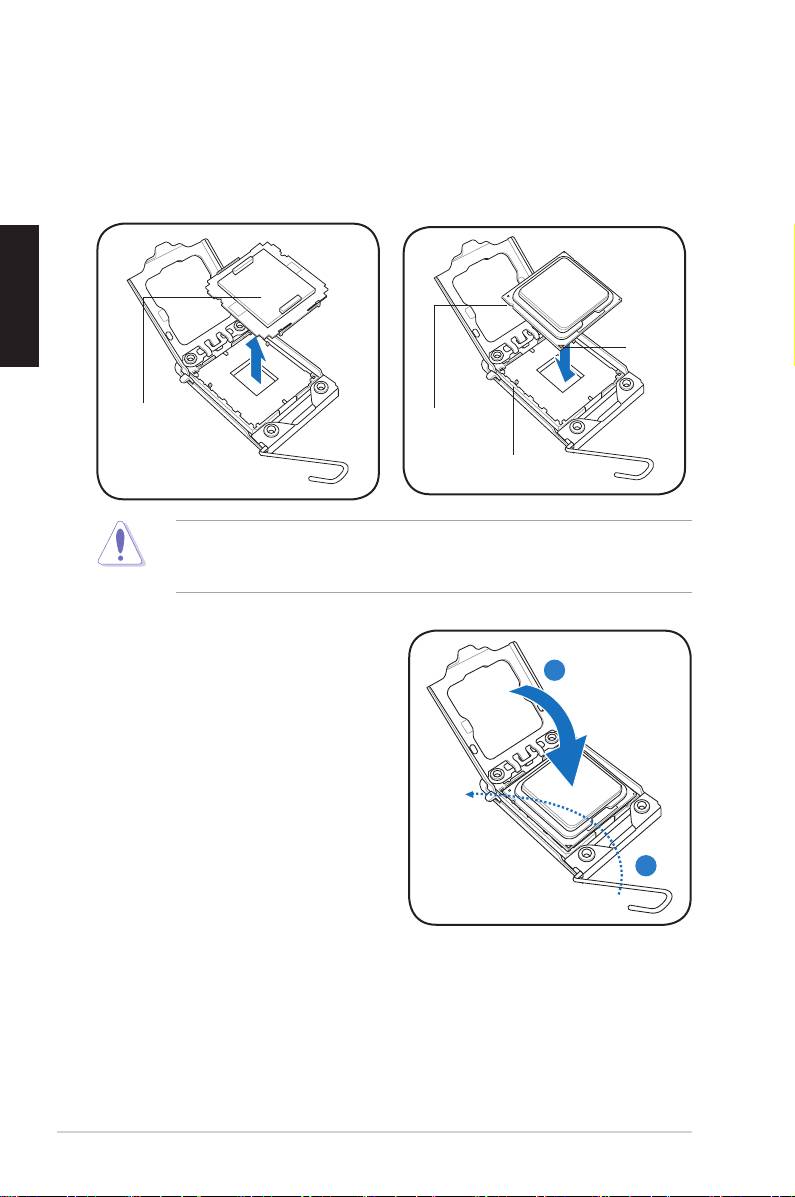
1.1.2 Intel LGA1366 Socket
Retention tab
1. Locate the CPU socket on the
motherboard.
A
2. Press the load lever with your
thumb (A), then move it to the left
(B) until it is released from the
retention tab.
B
Load lever
To prevent damage to the socket
pins, do not remove the PnP cap
unless you are installing a CPU.
3. Lift the load lever in the direction of
Load plate
the arrow to a 135º angle.
4. Lift the load plate with your thumb
4
and forenger to a 100º angle.
3
6 Chapter 1: Quick Start
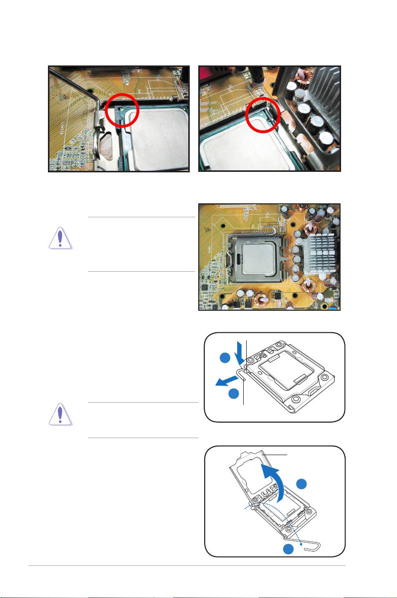
5. Remove the PnP cap from the CPU
6. Position the CPU over the socket,
socket.
ensuring that the gold triangle is on
the bottom‑left corner of the socket,
and then t the socket alignment key
into the CPU notch.
Gold
triangle
mark
PnP cap
CPU notch
Alignment key
The CPU ts in only one correct orientation. DO NOT force the CPU into the
socket to prevent bending the connectors on the socket and damaging the CPU!
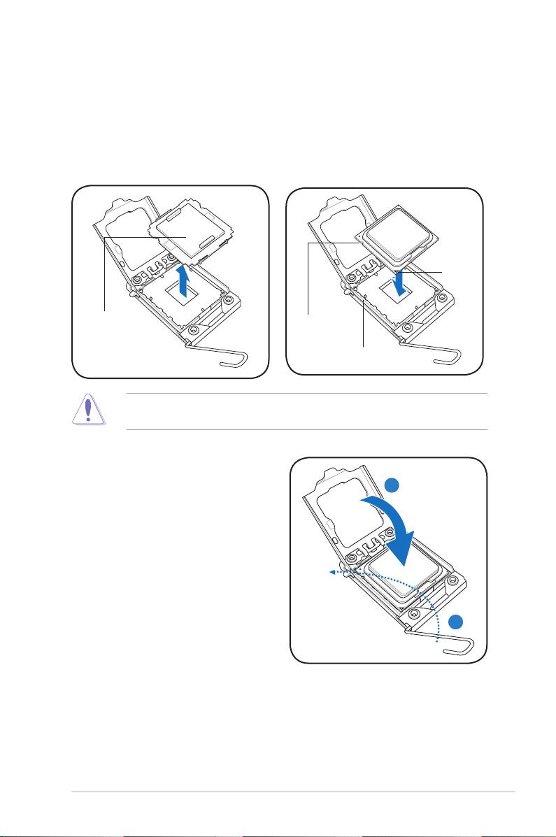
8. Close the load plate (A), and then
push the load lever (B) until it snaps
A
into the retention tab.
B
ASUS Motherboard installation guide 7

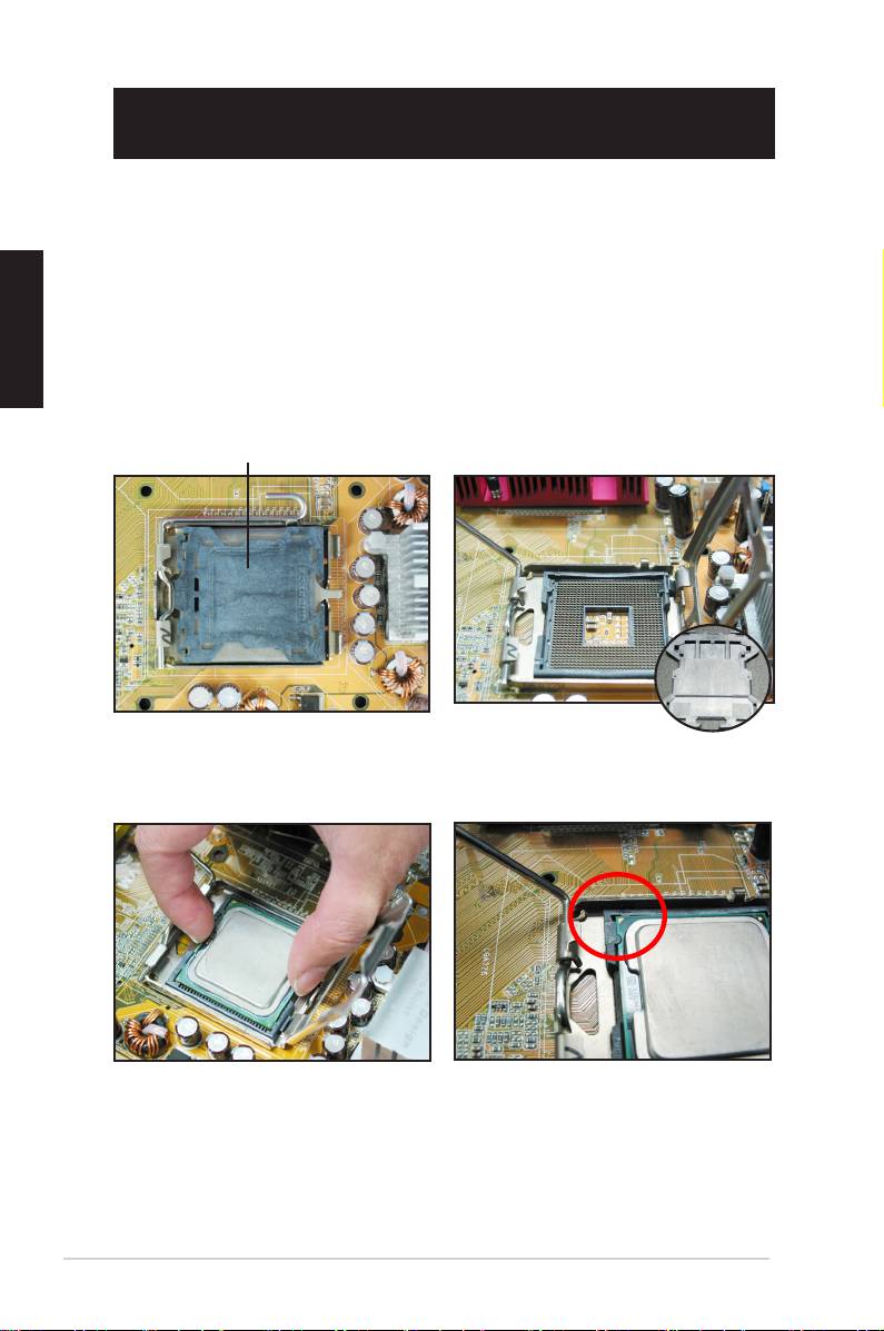
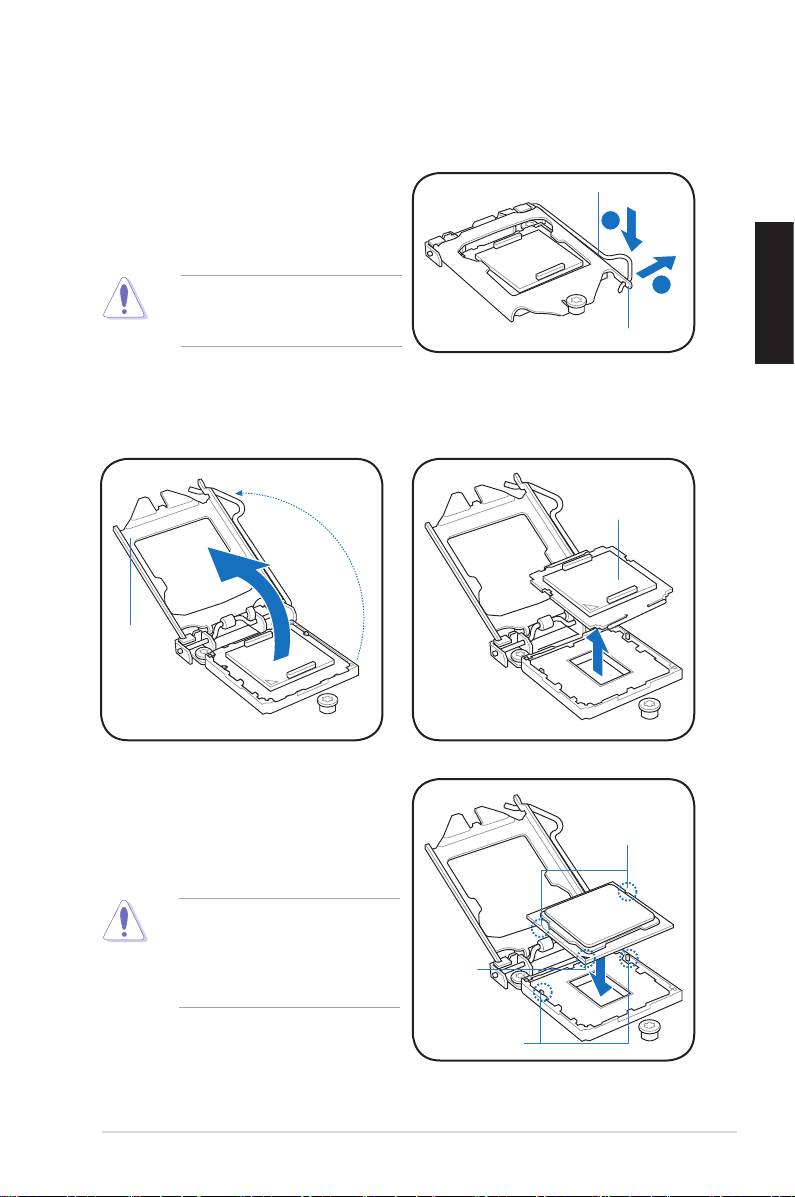
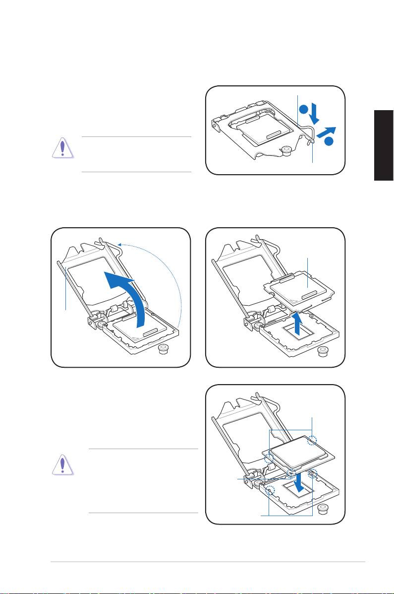
1.1.3 Intel LGA1156 Socket
1. Locate the CPU socket on the motherboard.
To prevent damage to the socket
pins, do not remove the PnP cap
unless you are installing a CPU.
8 Chapter 1: Quick Start
A
B
2. Press the load lever with your
Load lever
thumb (A), and then move it to the
right (B) until it is released from the
retention tab.
Retention tab
3. Lift the load lever in the direction
4. Remove the PnP cap from the
of the arrow until the load plate is
CPU socket.
completely lifted.
PnP cap
Load plate
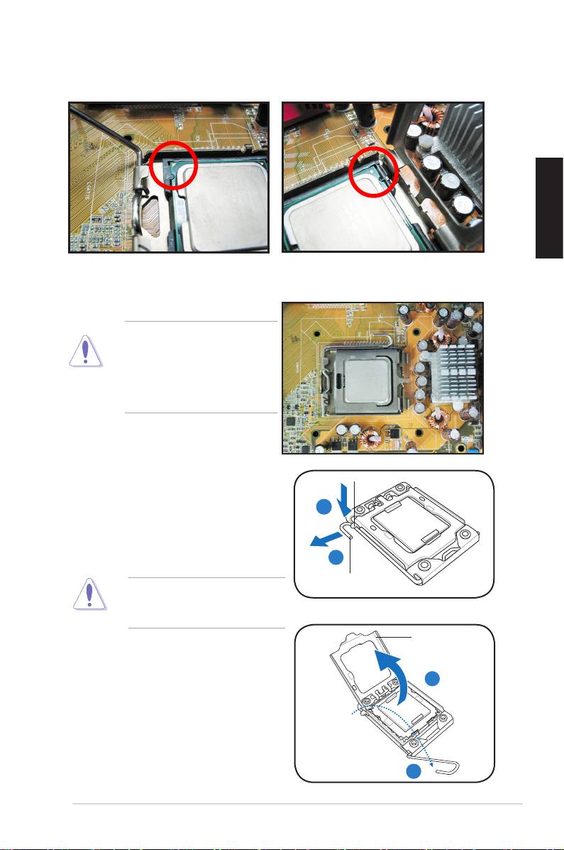
5. Position the CPU over the socket,
ensuring that the gold triangle is on
the bottom‑left corner of the socket,
CPU notches
and then t the socket alignment
keys into the CPU notches.
The CPU ts in only one correct
orientation. DO NOT force the
CPU into the socket to prevent
Gold
triangle
bending the connectors on the
mark
socket and damaging the CPU!
Alignment keys
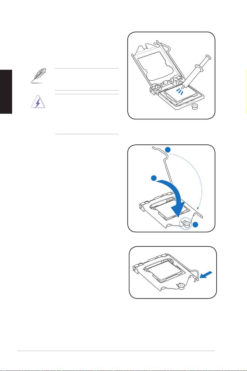
7. Close the load plate (A), and
then push down the load lever
(B), ensuring that the front edge
of the load plate slides under the
retention lock (C).
ASUS Motherboard installation guide 9
B
A
C
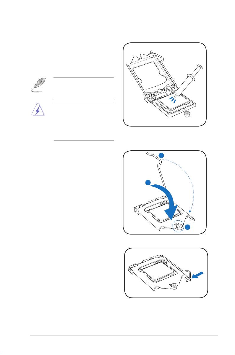
6. Apply some Thermal Interface
Material to the exposed area of
the CPU that the heatsink will be
in contact with, ensuring that it is
spread in an even thin layer.
Some heatsinks come with
pre‑applied thermal paste. If
so, skip this step.
The Thermal Interface Material
is toxic and inedible. DO NOT
eat it. If it gets into your eyes
or touches your skin, wash
it off immediately, and seek
professional medical help.
8. Insert the load lever under the
retention tab.
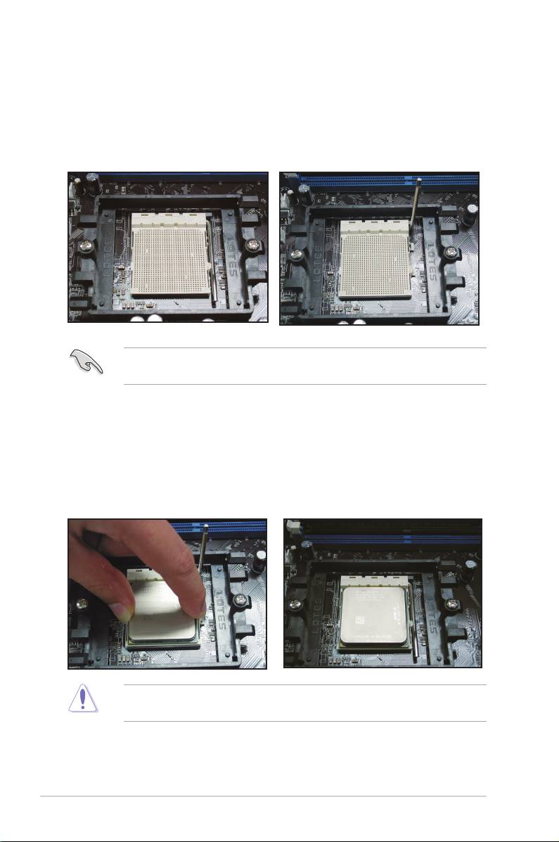
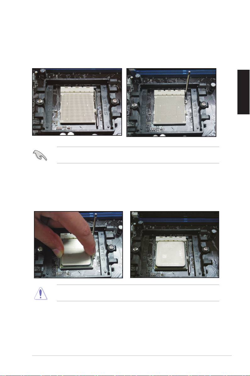
1.1.4 AMD AM2 Socket
1. Locate the CPU socket on the
2. Press the lever sideways to unlock
motherboard.
the socket, then lift it up to a 90º
angle.
Ensure that the socket lever is lifted up to 90º angle. Otherwise, the CPU will
not t in completely.
3. Position the CPU above the socket
4. When the CPU is in place, push
such that the CPU corner with the
down the socket lever to secure the
gold triangle matches the socket
CPU. The lever clicks on the side tab
corner with a small triangle.
to indicate that it is locked.
Carefully insert the CPU into the
socket until it ts in place.
The CPU ts in only one correct orientation. DO NOT force the CPU into the
socket to prevent bending the connectors on the socket and damaging the CPU!
10
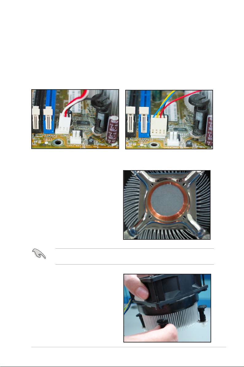
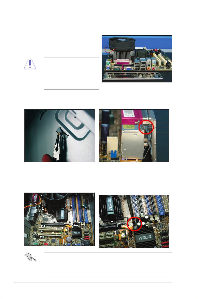
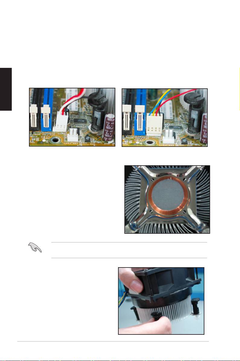
1.2 Installing the heatsink and fan
To install the CPU heatsink and fan:
1. Select an Intel-certied or AMD-certied heatsink and fan assembly based on your
motherboard. There are 3‑pin (left) and 4‑pin (right) fan connectors. Only CPU fans
with 4‑pin connectors supports the ASUS Q‑Fan technology.
For Intel-certied heatsink:
2. Some heatsinks will come with
pre‑applied thermal paste. If so,
do not scrape it off and remove
the protective lm only before
installation. If not, before installing
the heatsink, apply several drops of
thermal paste to the exposed area
of the CPU that the heatsink will
be in contact with. Ensure that it is
spread in an even thin layer.
To prevent contaminating the paste, DO NOT spread the paste with your nger
directly.
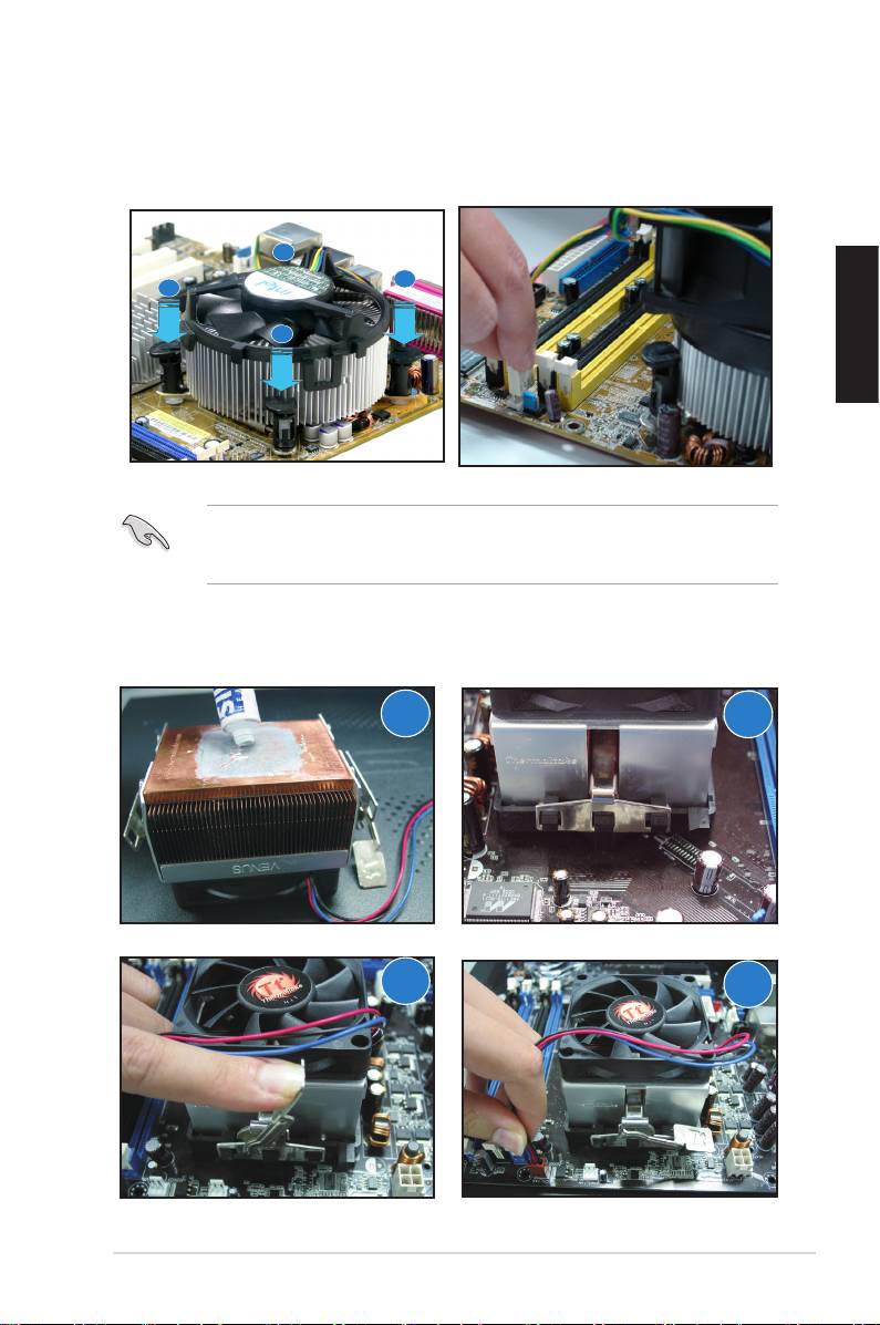
3. Orient each fastener with the
narrow end of the groove pointing
outward.
ASUS Motherboard installation guide 11
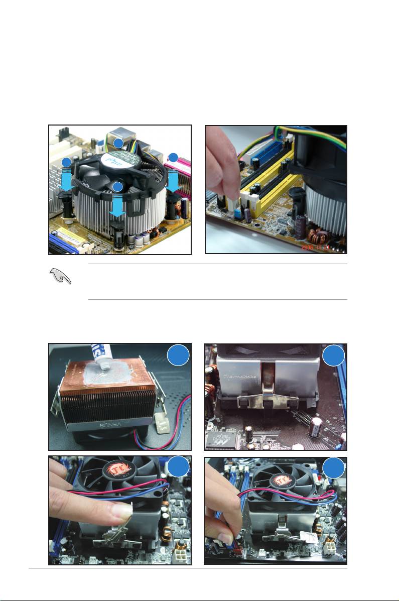
4. Push down two fasteners at a time
5. Connect the CPU fan cable to the
in a diagonal sequence to secure
corresponding connector on the
the heatsink and fan assembly in
motherboard.
place.
B
A
A
B
DO NOT forget to connect the CPU fan connector! Hardware monitoring errors
can occur if you fail to plug this connector and we suggest you use an omni‑
directional heatsink to gain the maximum heat dissipation area.
For AMD-certied heatsink:
Follow the instructions below to install an AMD-certied heatsink.
1
2
3
4
12 Chapter 1: Quick Start
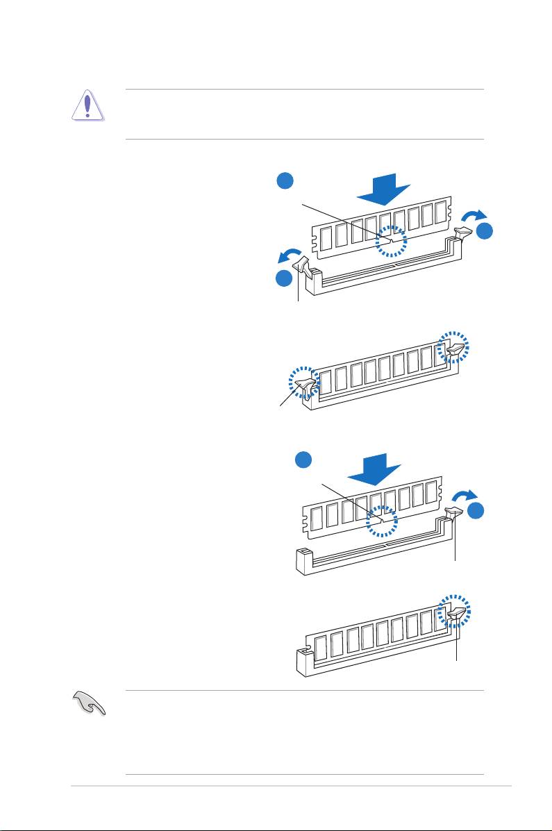
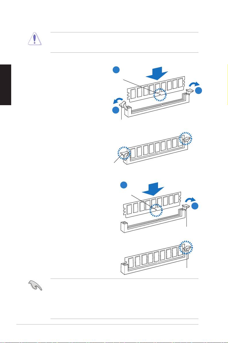
1.3 Installing a DIMM
Ensure to unplug the power supply before adding or removing DIMMs or other
system components. Failure to do so may cause severe damage to both the
motherboard and the components.
Installing a DIMM on a double clip DIMM socket
1. Unlock a DIMM socket by
2
pressing the retaining clips
DIMM notch
outward.
2. Align a DIMM on the socket
1
such that the notch on the DIMM
matches the break on the socket.
1
Unlocked retaining clip
3. Firmly insert the DIMM into the
socket until the retaining clips
snap back in place and the DIMM
is properly seated.
Locked Retaining Clip
Installing a DIMM on a single clip DIMM socket
1. Unlock a DIMM socket by
2
pressing the retaining clip
DIMM notch
outward.
2. Align a DIMM on the socket
1
such that the notch on the DIMM
matches the break on the socket.
Unlocked retaining clip
3. Firmly insert the DIMM into the
socket until the retaining clip
snaps back in place and the
DIMM is properly seated.
Locked Retaining Clip
• A DIMM is keyed with a notch so that it ts in only one direction. DO NOT
force a DIMM into a socket to avoid damaging the DIMM.
• To install two or more DIMMs, refer to the user guide bundled in the
motherboard package.
• Refer to the user guide for qualied vendor lists of the memory modules.
ASUS Motherboard installation guide 13
1.4 Installing the motherboard
1. I/O ports differ with motherboards.
Use and install the rear I/O shield
that comes with the motherboard
package only.
Some sharp edges and points
might cause physical injury. We
recommend you put on cut or
puncture resistant gloves before
motherboard and I/O shield
installation.
2. Install the standoffs to the
3. The I/O shield edge springs may
matched screw holes on the metal
damage the I/O ports. Be cautious
plate.
when installing the I/O shield.
4. Position the I/O side of the
5. Insert and loosely tighten each
motherboard toward the rear
screw in a diagonal sequence rst.
of the chassis and place the
After all the screws have been
motherboard into the chassis.
inserted, drive the screws until
they are nger-tight.
• You may remove the metal slot covers for the expansion cards at the back
of the chassis before installing the motherboard. For some chassis models,
it might be difcult to remove the expansion slot cover after the installation.
• DO NOT over‑tighten the screws. Doing so may damage the motherboard.
14 Chapter 1: Quick Start
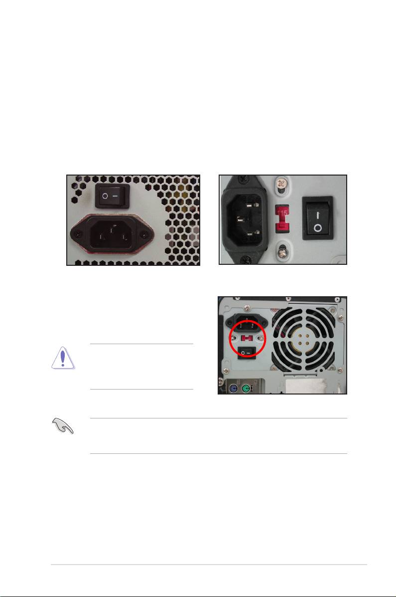
1.5 Installing the power supply unit
There are two kinds of commonly‑used power supply units. One is with Active
Power Factor Correction (PFC) and the other with passive PFC.
1. Select a power supply unit.
Power supply with active PFC:
Power supply with passive PFC:
Active PFC automatically corrects
Passive PFC requires user to
the AC input voltage.
manually adjust the AC input
voltage.
2. If you are using a power supply
with passive PFC, adjust to the
correct AC input voltage in your
area.
Failure to adjust the power
supply to the correct AC input
voltage will seriously damage
the system.
Use power supply units with safety certication only. Using unstable power
supply units can damage your motherboard and other components. Refer to the
user guide for power supply units that meet the motherboard requirements.
ASUS Motherboard installation guide 15
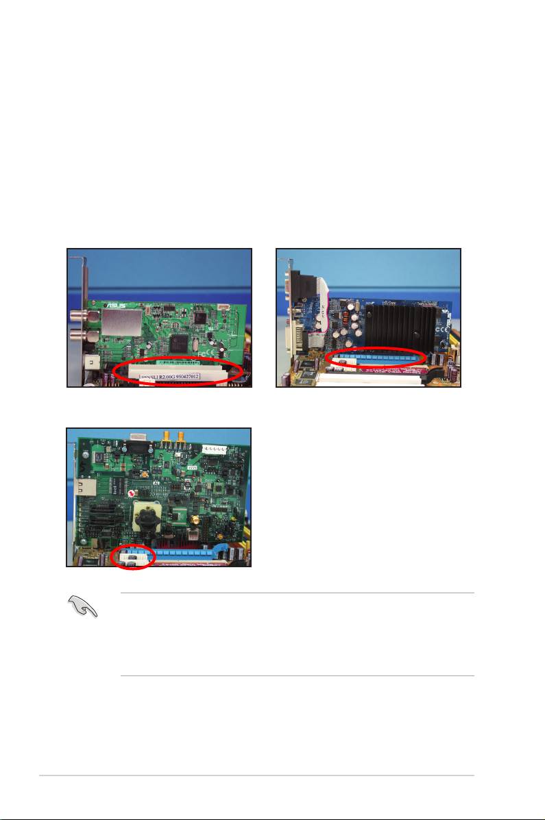
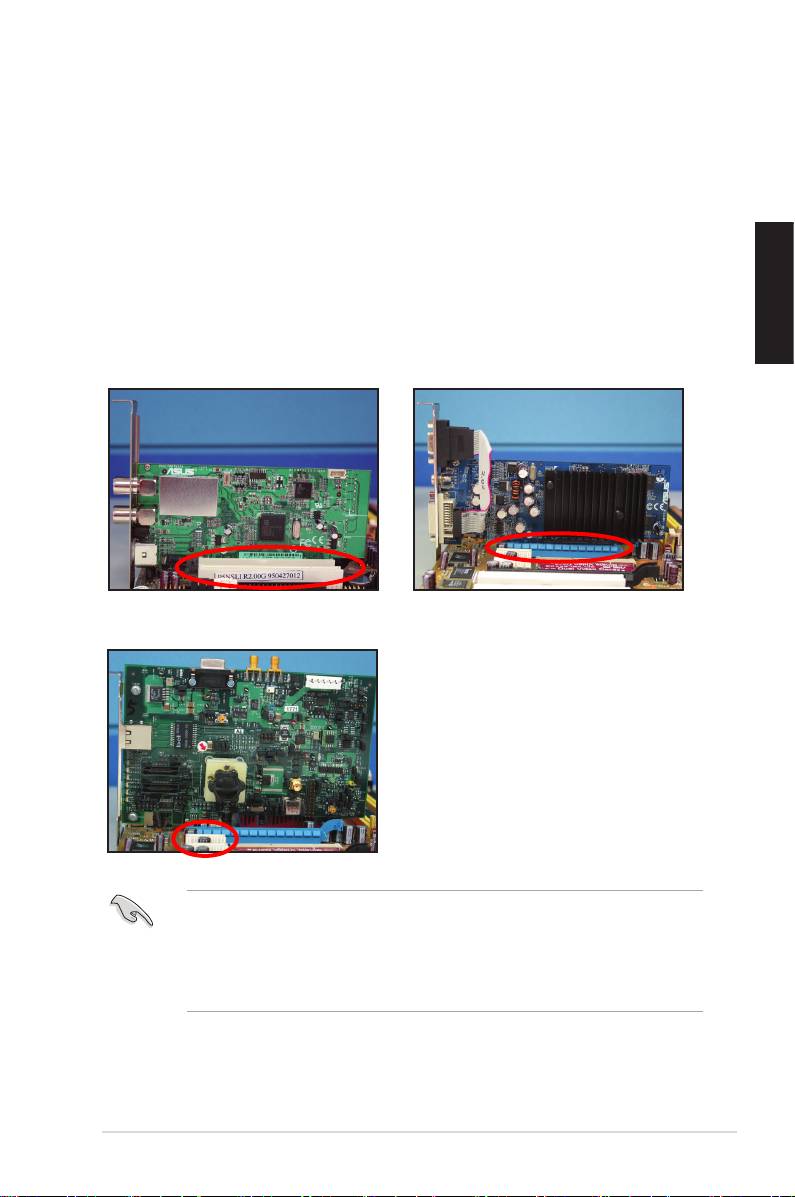
1.6 Installing an expansion card
To install an expansion card:
1. Remove the metal slot cover opposite the expansion card slot where you
wish to install an expansion card.
2. Install the expansion card and ensure that it is properly seated on the slot.
3. Screw to secure the card on the slot.
4. Repeat the previous steps to install another expansion card.
PCI card PCIE x16 card
PCIE x1 card
• Refer to the card documentation for the card conguration details, and to
the motherboard user guide in case you need to configure any jumpers
after installing the expansion card.
• Refer to the motherboard user guide for the instructions of the expansion
card signal cable connection.
16 Chapter 1: Quick Start
1.7 Installing disk drives
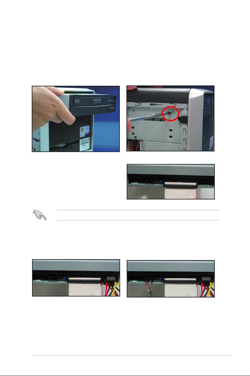
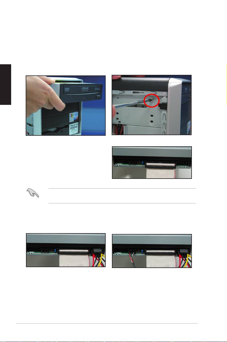
1.7.1 PATA optical disk drive
1. Remove the dummy cover and
2. Align with the screw holes and
slide the optical disk drive into the
secure the disk drive with screws.
bay.
3. Orient and plug the IDE cable into
the optical drive. The red stripe on
the IDE cable is the pin1 end and
should match the dimple marking
Pin1 on the optical drive.
IDE cables are dummy‑proof. Never force the IDE cable into the connector.
4. Connect the 4‑pin power cable to
5. Attach the audio cable to the
the optical drive.
connector on the optical drive.
ASUS Motherboard installation guide 17
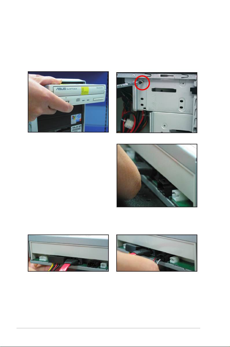
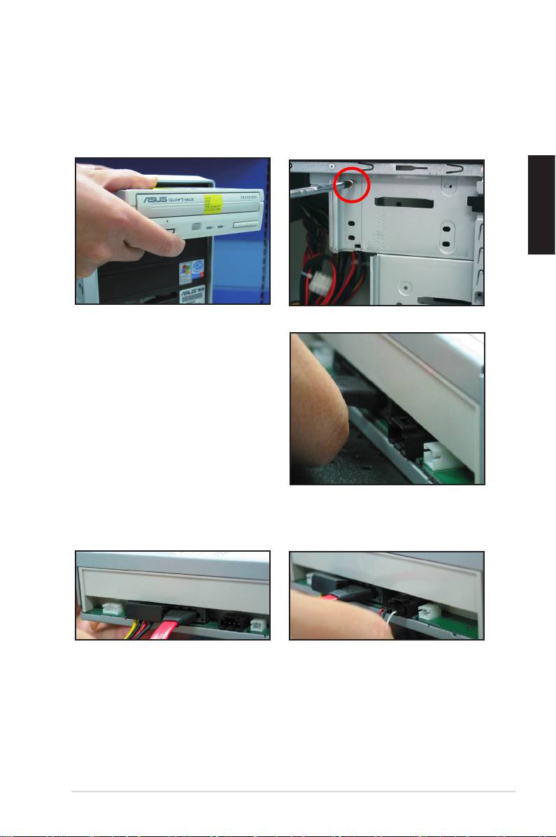
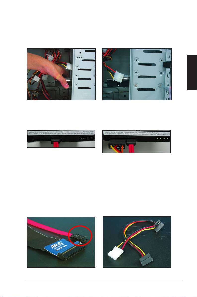
1.7.2 SATA optical disk drive
1. Remove the dummy cover and
2. Align with the screw holes and
slide the optical disk drive into the
secure the disk drive with screws.
bay.
3. Orient and plug the SATA cable into
the optical drive. SATA cables are
dummy‑proof. Never force a SATA
cable into the connector.
4. Connect the SATA power cable to
5. Attach the audio cable to the
the the optical drive.
connector on the optical drive.
18 Chapter 1: Quick Start
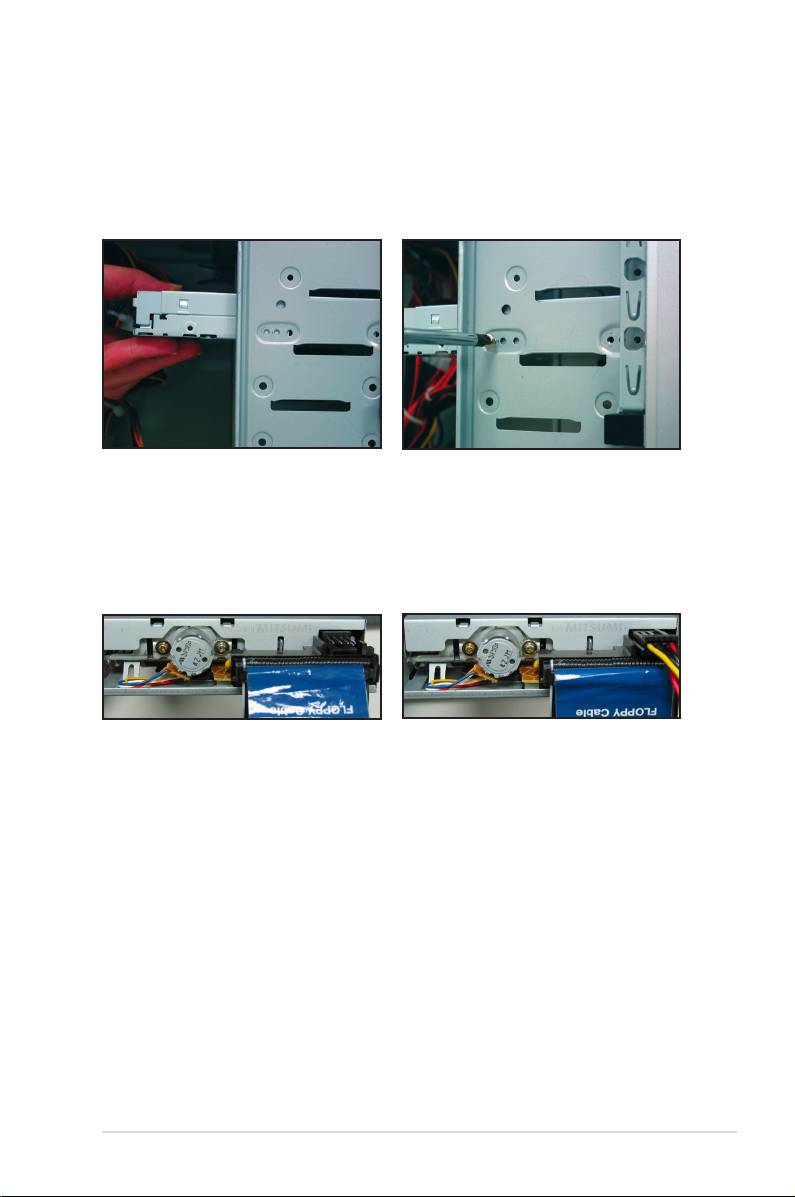
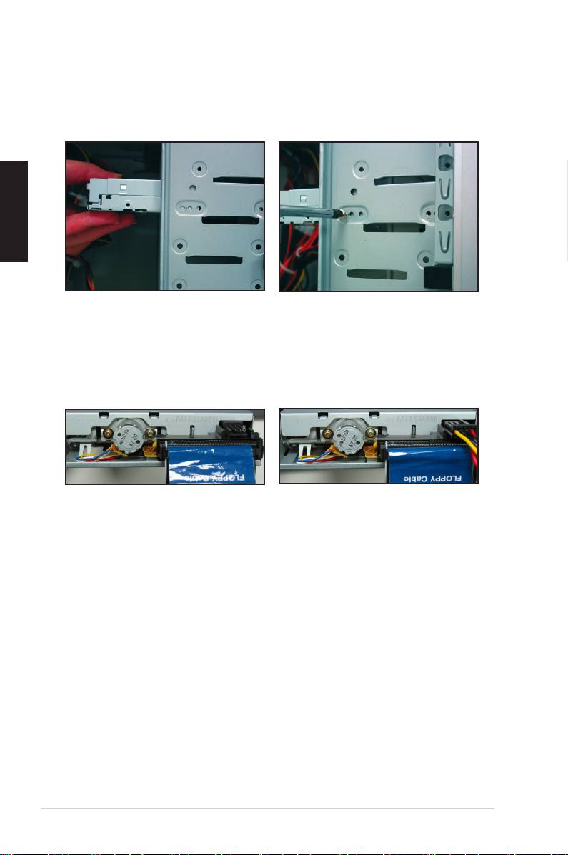
1.7.3 Floppy disk drive
1. Remove the dummy cover and
2. Align with the screw holes and
insert the oppy disk drive into the
secure the disk drive with screws.
bay.
3. Orient and plug the oppy interface
4. Connect the oppy power cable to
cable into the oppy disk drive. The
the connector at the back of the
red stripe on the cable is the pin1
oppy disk drive.
end and should match pin1 on the
oppy disk drive.
ASUS Motherboard installation guide 19
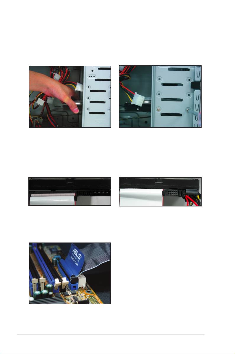
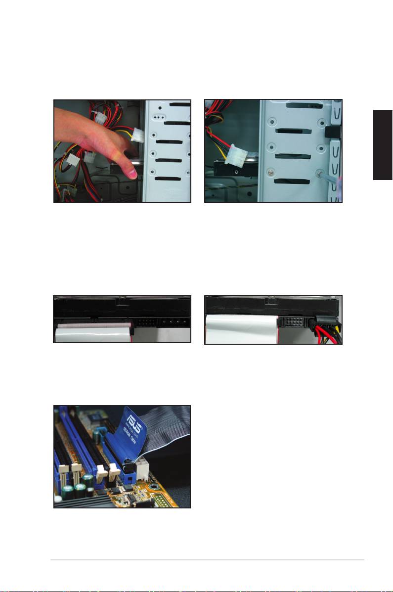
1.7.4 PATA hard disk drive
1. Insert the PATA hard disk drive into
2. Align with the screw holes and
the bay.
secure the disk drive with screws.
3. Orient and connect the signal cable
4. Connect the 4‑pin power cable to
to the hard disk drive. The red stripe
the connector at the back of the
on the cable is the pin1 end. Match
hard disk drive.
the dummy‑proof notch and do not
force the cable into the connector.
5. Attach the other end of the signal
cable to the corresponding slot on
the motherboard.
20 Chapter 1: Quick Start
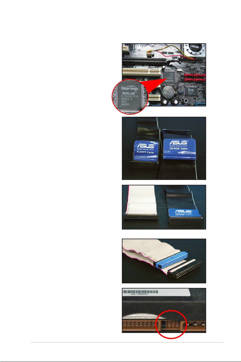
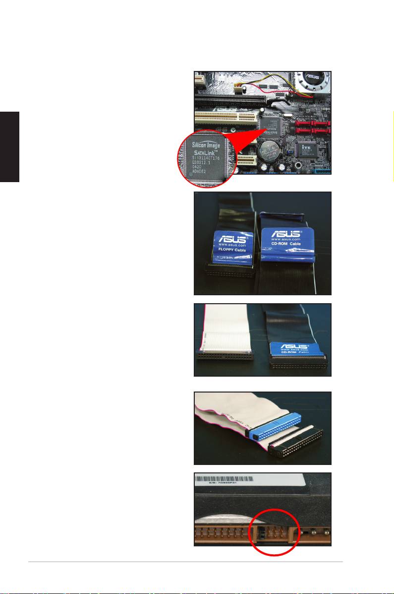
Notes for installing PATA hard disk drive
• If your operating system is installed
to the hard disk drive controlled by
the RAID or other controllers, you
have to install the controller driver
to the hard disk rst.
• The cables are designed with pull
tabs. Just easily install the disk
drives based on the cable labels.
To prevent damaging the pins, pull
the cable tabs to disconnect the
cable.
• There are two cables for ATA IDE
disk drives, the newer 80‑wire
(right) and the older 40‑wire (left)
cables. For ATA66/100/133 disk
drives, only the 80‑wire cable can
offer a better performance. The
40‑wire cables are usually for the
optical drives.
• The cable connector is color‑
coded. The blue one is for the host
connector, and the black/gray one
is for the primary/secondary disk
drive.
• When connecting two IDE devices,
you have to set the jumpers to
different position, one in master
and one in slave. If you are using
an 80‑wire cable, you can use the
cable select style.
ASUS Motherboard installation guide 21
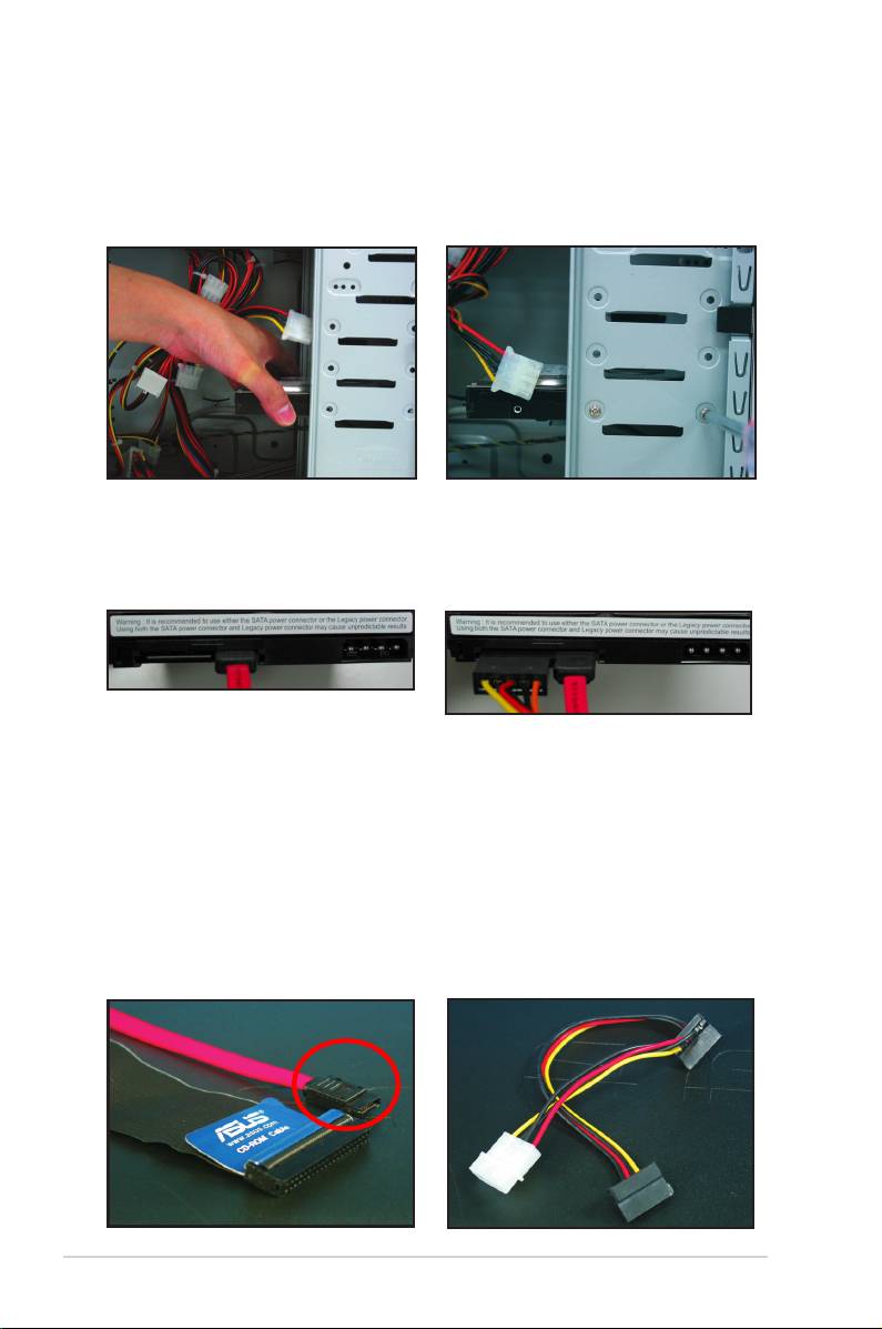
1.7.5 SATA hard disk drive
1. Insert the SATA hard disk drive into
2. Align with the screw holes and
the bay.
secure the disk drive with screws.
3. Orient and connect the SATA cable
4. Connect the SATA power cable to
to the hard disk drive. The cable can
the connector at the back of the
only t in one direction.
hard disk drive.
Notes for installing SATA hard disk drive
• Serial ATA (SATA) interface
• The SATA power cable connector
provides higher data transmission
is different from the traditional
speed, and better voltage tolerance.
4‑pin power connector. ASUS
The narrow design of the SATA
motherboard bundles power adapter
cable also solves cabling issues
cables for you in case your power
and allows better airow in the
supply unit does not include this
chassis.
new connector.
22 Chapter 1: Quick Start
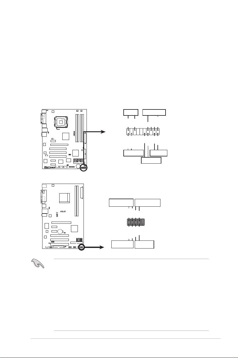
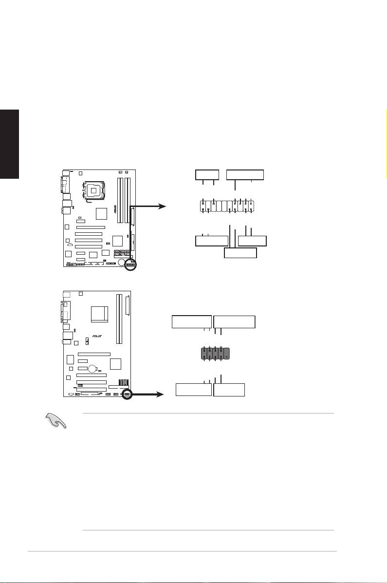
1.8 Front panel cables
To connect the front panel cables:
• RESET (Reset Switch)
• PLED (Power LED)
• PWRSW (Power Switch)
• IDE_LED (IDE Hard Disk Active LED)
• SPEAKER (Speaker Connector)
ASUS Motherboard installation guide 23
PWR LED PWR BTN
M2N-X
PLED+
PLED‑
PWR
GNDReset
F_PANEL
Ground
IDELED+
IDELED‑
HD LED RESET
PLED SPEAKER
P5B-E
PLED+
PLED-
+5V
Ground
Ground
Speaker
®
PANEL
PWR
Reset
Ground
Ground
IDE_LED+
IDE_LED-
IDE_LED
RESET
PWRSW
*
Requires an ATX power supply.
20-8 pin front panel connector
PIN1
PIN1
10-1 pin front panel connector
• The front panel cables of your chassis may differ with models or designs.
Connect these connectors to the motherboard according to the label.
• If the LEDs do not light up and the pin location is correct, you might have
mistaken the ground pins with the signal pins. Usually the white wire stands
for the ground pins and the color‑coded wire for the signal pins.
• The SPEAKER, RESET and PWRSW front panel cables have no specic
orientation, while IDE_LED and PLED cables do. Connect the cable PIN1
to the connector PIN1 on the motherboard.
• The front panel connector varies with your motherboard model, refer to the
user guide for more information.
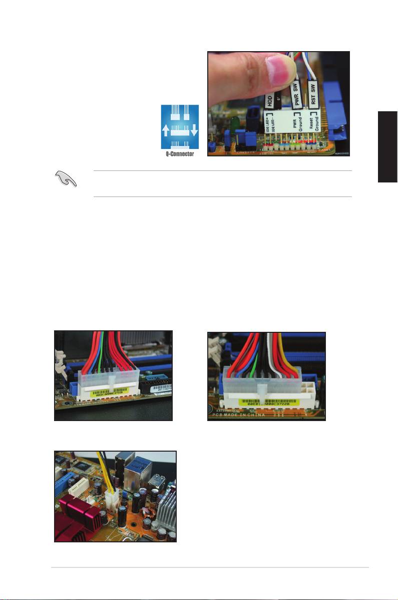
ASUS Q-Connector
ASUS Q‑Connector’s one step installation
saves your time from struggling with the
messy front panel cables. Refer to the
user guide for details.
The Q‑connector is available in selected models. Refer to the user guide for
details.
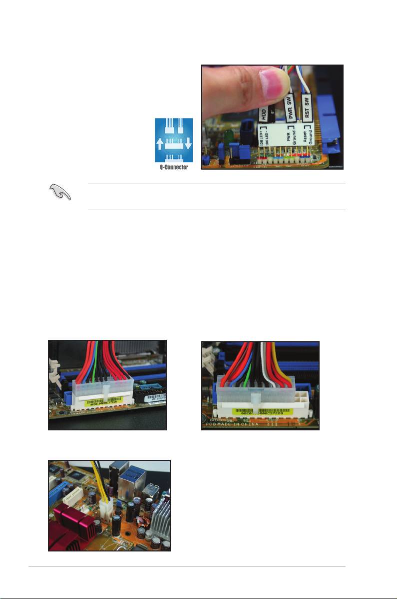
1.9 Connecting the ATX power
The ATX power connectors can t in only one orientation. Use the side clip to hook
the connectors to the motherboard. DO NOT force the male power connectors into
the female counterparts on the motherboard. Usually there will be two connectors
on the motherboard: 24‑pin and 4‑pin power connectors. Some older power supply
units may only have 20-pin power connector which also ts the 24-pin power
connector on the motherboard.
20-pin power connector
24-pin power connector
(on the 24-pin female counterpart)
4-pin power connector
24 Chapter 1: Quick Start
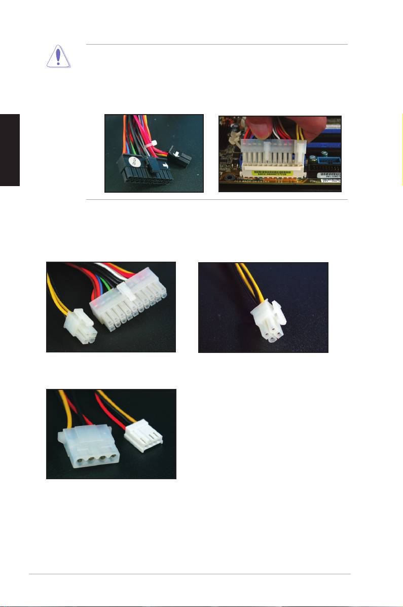
• DO NOT attach the external AC power when connecting the power
connectors to the motherboard.
• Ensure the power connectors are rmly secured to the motherboard.
• If your power supply supports 20‑pin+4‑pin, you are able to combine these
two connectors and install to the 24‑pin connectors on the motherboard.
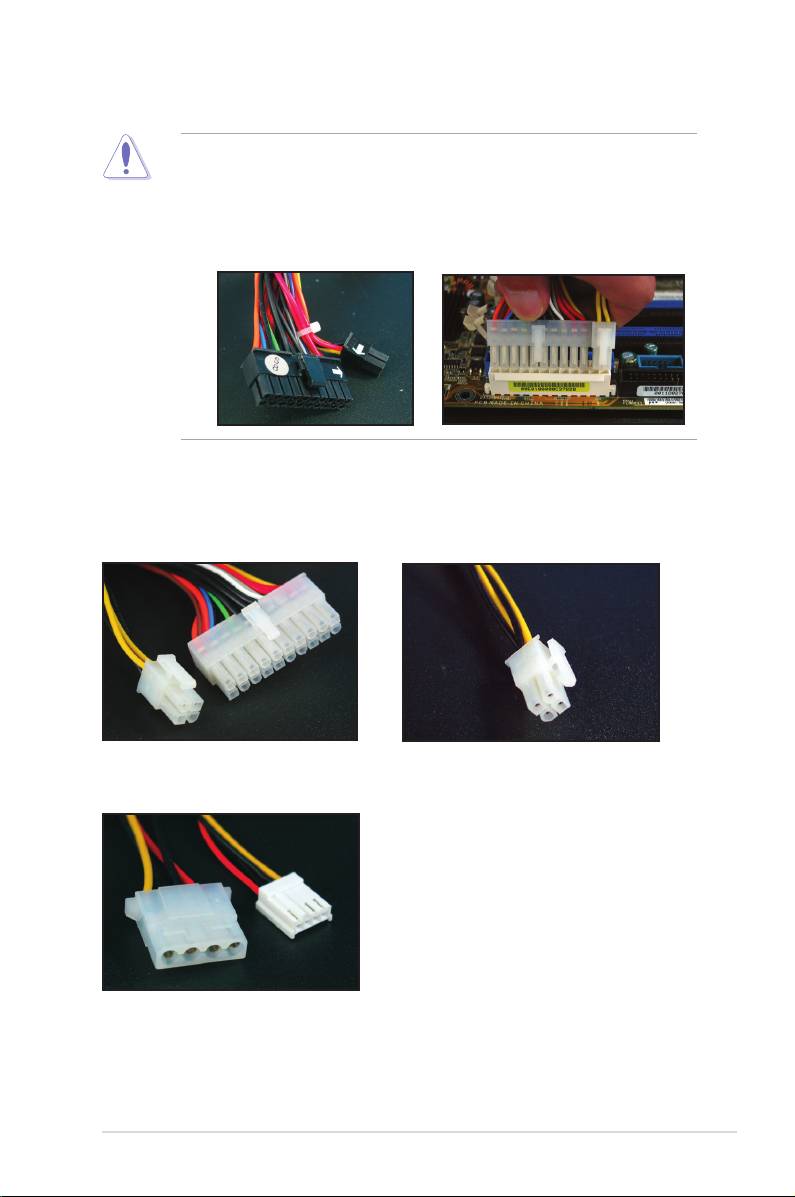
Power connectors
20+4 (24) pin ATX connector
4-pin ATX connector
peripheral power connector (left)
oppy power connector (right)
ASUS Motherboard installation guide 25
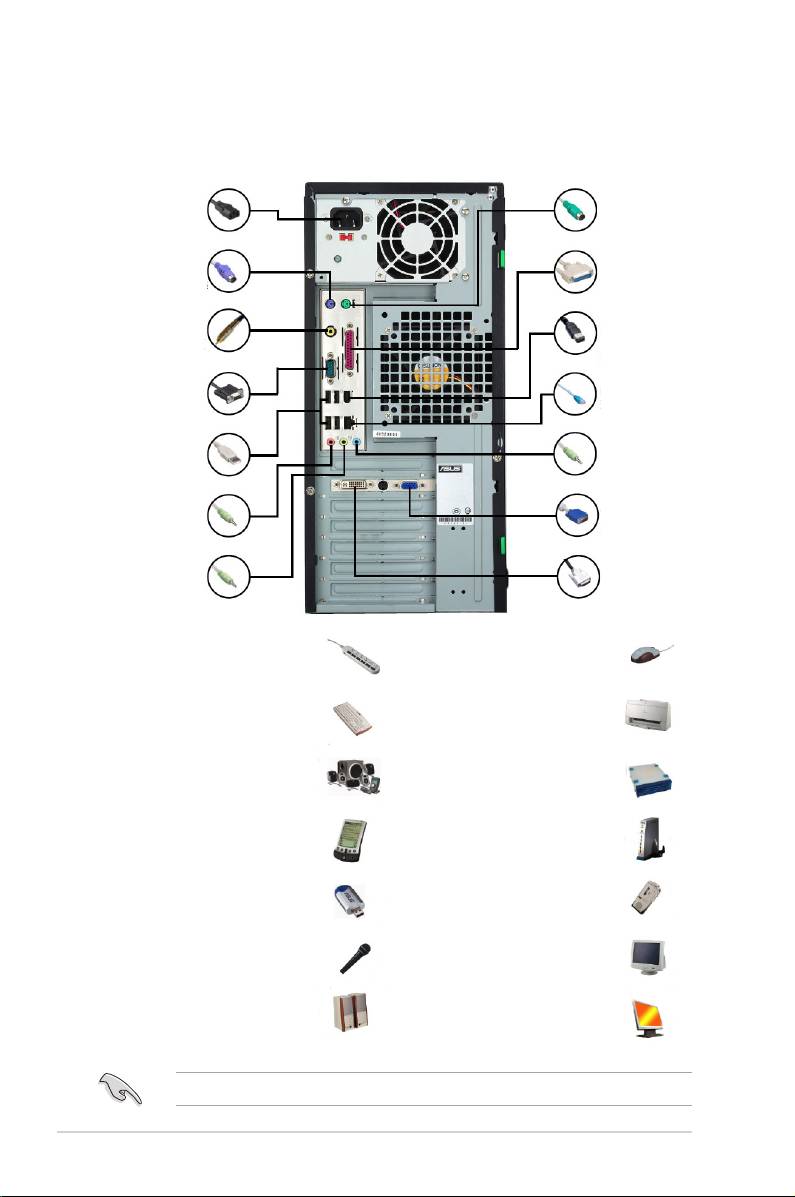
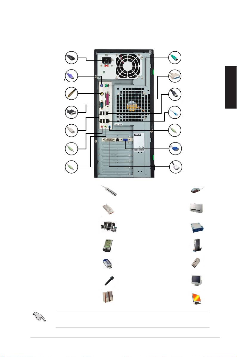
1.10 Peripheral devices and accessories
Refer to the gure for connecting the peripheral devices and accessories.
1. AC power plug
8. PS/2
mouse port
2. PS/2 keyboard
9. Parallel port
port
3. S/PDIF out port
10. IEEE1394 port
4. Serial port
11. LAN (RJ45) port
5. USB port
12. Line in port
13. Video graphics
6. Microphone port
adapter port
7. Line out port 14. DVI port
1. AC Power plug + power
8. PS/2 mouse port +
extension cord
mouse
2. PS/2 keyboard port +
9. Parallel port + printer
keyboard
3. S/PDIF out port + digital
10. IEEE1394 port + external
5.1 speaker system
hard disk drive
4. Serial port + PDA dock
11. LAN (RJ45) port + modem
5. USB port + USB devices
12. Line in port + recorder
6. Microphone port +
13. VGA port + CRT monitor
microphone
7. Line out port + speaker
14. DVI port + LCD monitor
The rear panel connectors vary with models. Refer to the user guide for details.
26 Chapter 1: Quick Start
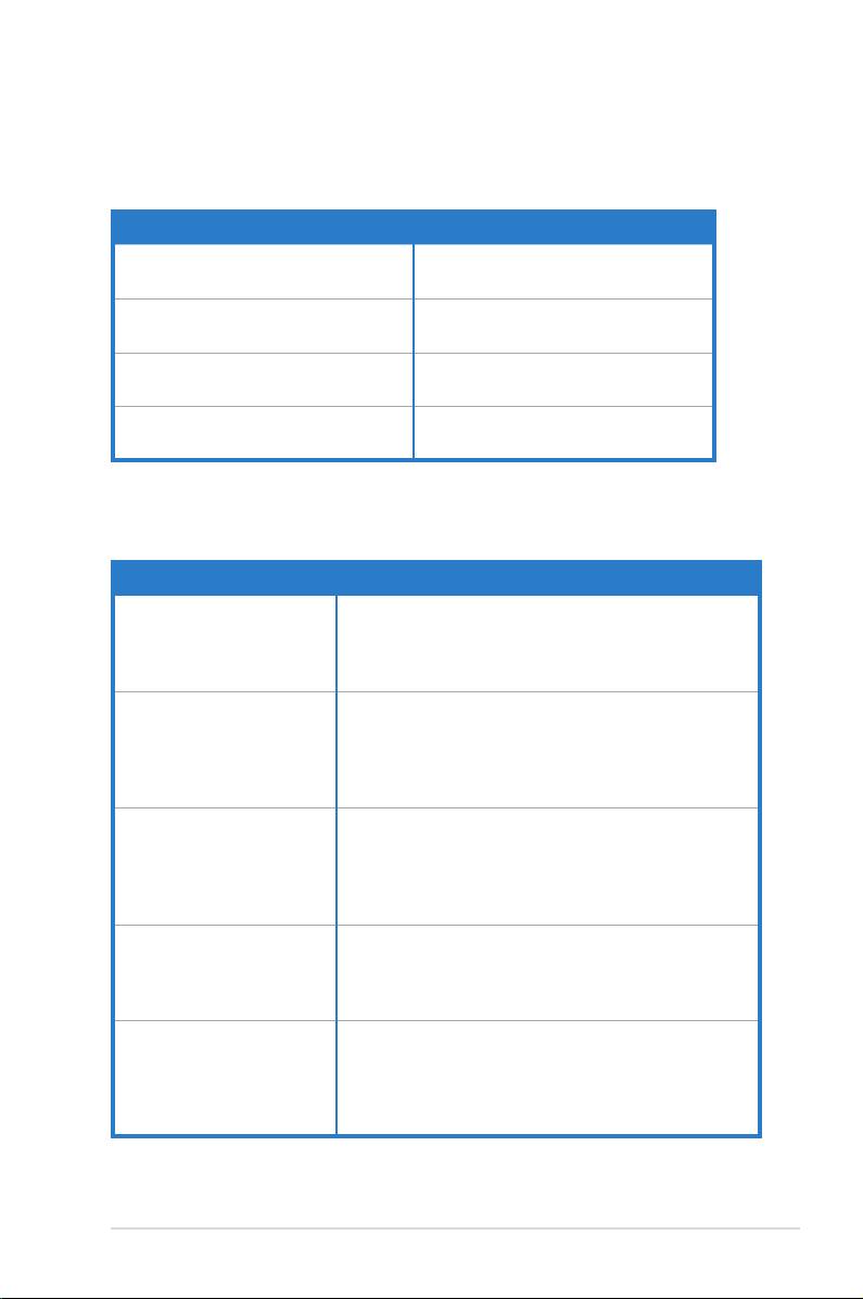
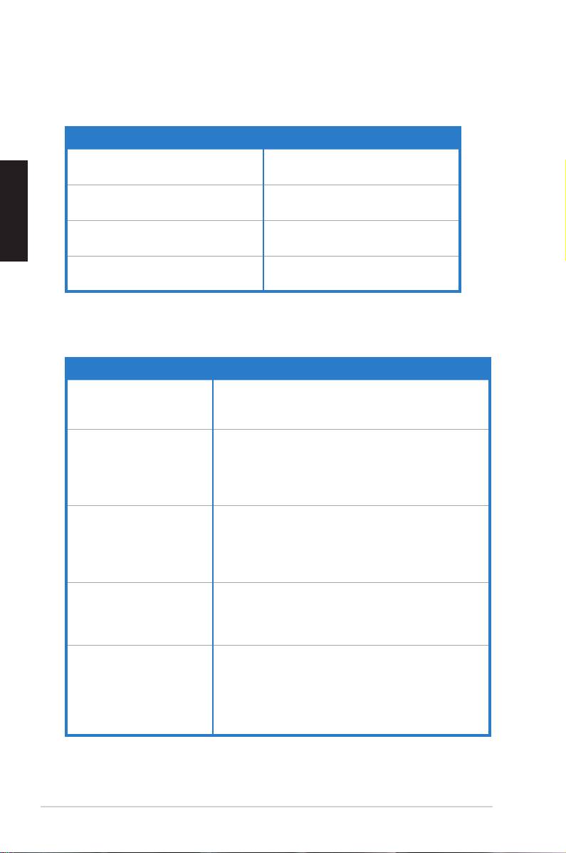
1.11 Startingupforthersttime
The system then runs the power‑on self tests or POST. While the tests are running,
the BIOS beeps.
BIOS Beep Description
One continuous beep followed by three
No VGA detected
short beeps
One continuous beep followed by two
No memory detected
short beeps then a pause (repeated)
One continuous beep followed by four
Hardware component failure
short beeps
(AMI BIOS)
Four short beeps Hardware component failure
(AWARD BIOS)
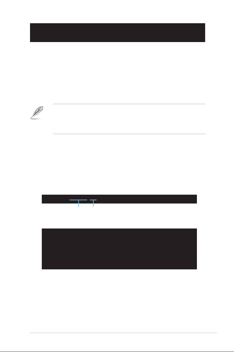
Troubleshooting
Trouble Action
• Cannot turn on the computer
Ensure the power cord is connected correctly.
• Power LED is not lit.
• Power supply fan is not
working.
The computer is on but the
• Ensure the monitor power is on and the VGA cable is
monitor is black.
connected correctly.
• Adjust the monitor brightness and contrast.
• Shut down the computer and remove the power cord.
Check whether the VGA card is installed rmly.
No memory detected • Ensure the memory module is correct.
• Ensure the DIMMS are rmly seated on the DIMM
socket.
• Ensure the memory module is from the qualied vedor
list. Refer to the user guide for the QVL.
Floppy Error
• Check the BIOS conguration about oppy disk drive.
(The indicator is always lit or
• Ensure the cables for the oppy disk drive is plugged
a warning message pops on
correctly.
the screen.)
Hard/optical disk drive error
• Ensure the jumper setting is correct. (Master/Slave)
(not recognized or detected)
• Check the BIOS conguration about hard/optical disk
drive.
• Ensure the device cables are rmly attached.
• Ensure the device drivers are installed.
ASUS Motherboard installation guide 27

28 Chapter 1: Quick Start
Chapter 2: Manage/update BIOS
2.1 AFUDOS utility
The AFUDOS utility allows you to update the BIOS le in DOS environment using
a bootable oppy disk with the updated BIOS le. This utility also allows you to
copy the current BIOS le that you can use as backup when the BIOS fails or gets
corrupted during the updating process.
Copying the current BIOS
To copy the current BIOS le using the AFUDOS utility:
• Ensure that the oppy disk is not write-protected and has at least 1024KB
free space to save the le.
• The succeeding BIOS screens are for reference only. The actual BIOS
screen displays may not be same as shown.
1. Copy the AFUDOS utility (afudos.exe) from the motherboard support CD/
DVD to a bootable oppy disk.
2. Boot the system in DOS mode, then at the prompt type:
afudos /o[lename]
where the [lename] is any user-assigned lename not more than eight
alphanumeric characters for the main lename and three alphanumeric
characters for the extension name.
A:\>afudos /oOLDBIOS1.rom
Main lename Extension name
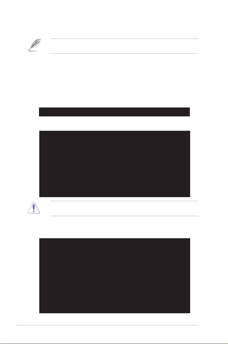
3. Press <Enter>. The utility copies the current BIOS le to the oppy disk.
A:\>afudos /oOLDBIOS1.rom
AMI Firmware Update Utility - Version 1.19(ASUS V2.07(03.11.24BB))
Copyright (C) 2002 American Megatrends, Inc. All rights reserved.
Reading ash ..... done
Write to le...... ok
A:\>
The utility returns to the DOS prompt after copying the current BIOS le.
Updating the BIOS le
To update the BIOS le using the AFUDOS utility:
1. Visit the ASUS website (www.asus.com) and download the latest BIOS le for
the motherboard. Save the BIOS le to a bootable oppy disk.
ASUS Motherboard installation guide 29
Write the BIOS lename on a piece of paper. You need to type the exact BIOS
lename at the DOS prompt.
2. Copy the AFUDOS utility (afudos.exe) from the motherboard support DVD to
the bootable oppy disk you created earlier.
3. Boot the system in DOS mode, then at the prompt type:
afudos /i[lename]
where [lename] is the latest or the original BIOS le on the bootable oppy
disk.
A:\>afudos /iP5K3D.ROM
4. The utility veries the le and starts updating the BIOS.
A:\>afudos /iP5K3D.ROM
AMI Firmware Update Utility - Version 1.19(ASUS V2.07(03.11.24BB))
Copyright (C) 2002 American Megatrends, Inc. All rights reserved.
WARNING!! Do not turn off power during ash BIOS
Reading le ....... done
Reading ash ...... done
Advance Check ......
Erasing ash ...... done
Writing ash ...... 0x0008CC00 (9%)
DO NOT shut down or reset the system while updating the BIOS to prevent
system boot failure!
5. The utility returns to the DOS prompt after the BIOS update process is
completed. Reboot the system from the hard disk drive.
A:\>afudos /iP5K3D.ROM
AMI Firmware Update Utility - Version 1.19(ASUS V2.07(03.11.24BB))
Copyright (C) 2002 American Megatrends, Inc. All rights reserved.
WARNING!! Do not turn off power during ash BIOS
Reading le ....... done
Reading ash ...... done
Advance Check ......
Erasing ash ...... done
Writing ash ...... done
Verifying ash .... done
Please restart your computer
A:\>
30 Chapter 2: Manage/update BIOS
2.2 Award BIOS Flash Utility
Updating the BIOS
The Basic Input/Output System (BIOS) can be updated using the AwardBIOS
Flash Utility. Follow these instructions to update the BIOS using this utility.
1. Download the latest BIOS le from the ASUS web site. Rename the le to
XXXXX.BIN (model name.BIN)and save it to a oppy disk, CD ROM or a
USB ash disk in FAT 16/12 format.
Save only the updated BIOS le in the disk to avoid loading the wrong BIOS le.
2. Copy the AwardBIOS Flash Utility (awdash.exe) from the Software folder of
the support CD to the oppy disk, CD ROM or a USB ash disk with the latest
BIOS le.
3. Boot the system in DOS mode using the bootable oppy disk, CD ROM or a
USB ash disk you created earlier.
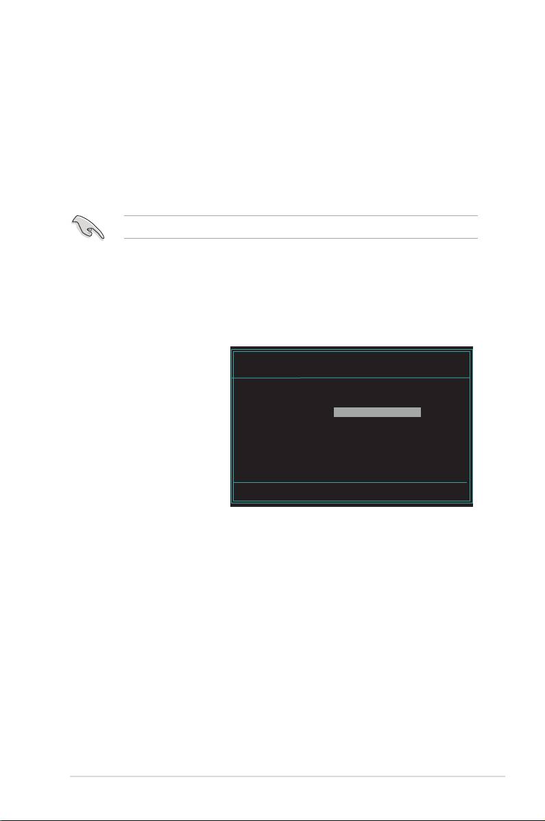
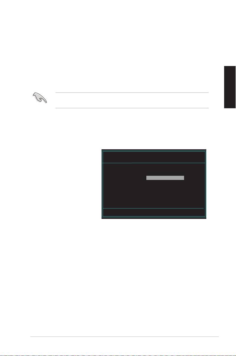
4. Under the DOS mode,
AwardBIOS Flash Utility for ASUS V1.14
use <X:> (X stands for
(C) Phoenix Technologies Ltd. All Rights Reserved
the name of the disk
For NF590-SLI-M2N32-SLI-DELUXE DATE:03/30/2006
Flash Type - PMC Pm49FL004T LPC/FWH
assignment) to switch to
the folder of oppy disk,
File Name to Program:
CD ROM or USB ash
disk you saved the BIOS
le and AwardBIOS Flash
Utility.
5. At the prompt, type
Message: Please input File Name!
awdash then press
<Enter>. The Award BIOS
Flash Utility screen appears.
ASUS Motherboard installation guide 31
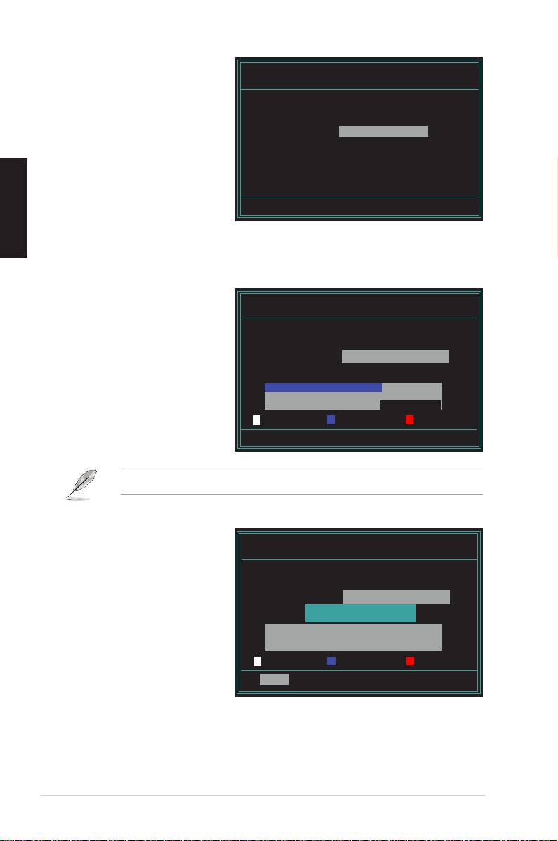
6. Type the BIOS le name in
AwardBIOS Flash Utility for ASUS V1.14
the File Name to Program
(C) Phoenix Technologies Ltd. All Rights Reserved
eld, then press <Enter>.
For NF590-SLI-M2N32-SLI-DELUXE DATE:03/30/2006
Flash Type - PMC Pm49FL004T LPC/FWH
File Name to Program: M2N32SLI.bin
Message: Do You Want To Save Bios (Y/N)
7. Press <N> when the utility prompts you to save the current BIOS le. The
following screen appears.
8. The utility veries the BIOS
AwardBIOS Flash Utility for ASUS V1.14
le in the oppy disk, CD
(C) Phoenix Technologies Ltd. All Rights Reserved
ROM or a USB ash disk
For NF590-SLI-M2N32-SLI-DELUXE DATE:03/30/2006
Flash Type - PMC Pm49FL004T LPC/FWH
and starts ashing the BIOS
le.
File Name to Program: M2N32SLI.bin
Programming Flash Memory - OFE00 OK
Write OK No Update Write Fail
Warning: Don’t Turn Off Power Or Reset System!
DO NOT turn off or reset the system during the ashing process!
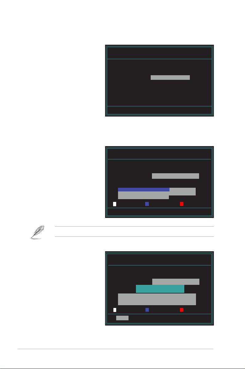
9. The utility displays a
AwardBIOS Flash Utility for ASUS V1.14
Flashing Complete
(C) Phoenix Technologies Ltd. All Rights Reserved
message indicating that
For NF590-SLI-M2N32-SLI-DELUXE DATE:03/30/2006
Flash Type - PMC Pm49FL004T LPC/FWH
you have successfully
ashed the BIOS le.
File Name to Program: M2N32SLI.bin
Flashing Complete
Remove the disk then
Press <F1> to Continue
press <F1> to restart the
system.
Write OK No Update Write Fail
F1
Reset
32 Chapter 2: Manage/update BIOS
Saving the current BIOS le
You can use the AwardBIOS Flash Utility to save the current BIOS le. You can
load the current BIOS le when the BIOS le gets corrupted during the ashing
process.
Ensure that the oppy disk, CD ROM or a USB ash disk has enough disk
space to save the le.
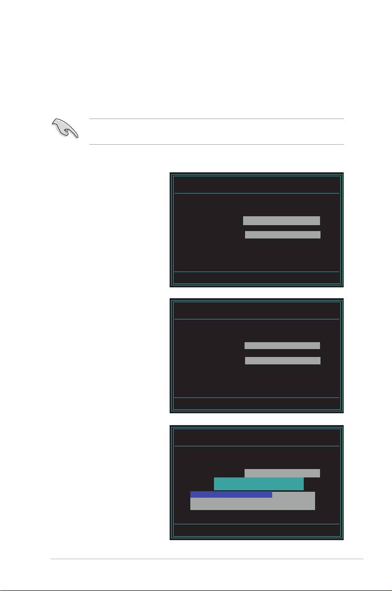
To save the current BIOS le using the AwardBIOS Flash Utility:
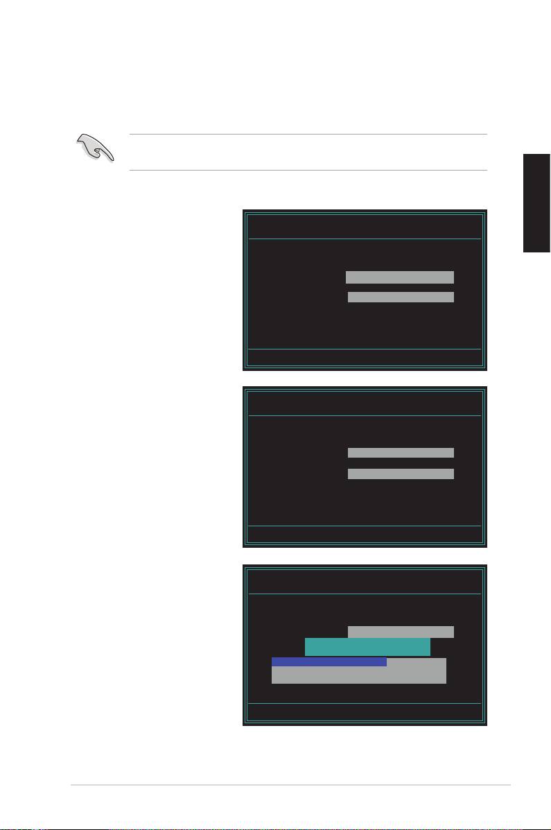
1. Follow steps 1 to 6 of the
AwardBIOS Flash Utility for ASUS V1.14
(C) Phoenix Technologies Ltd. All Rights Reserved
previous section.
For NF590-SLI-M2N32-SLI-DELUXE DATE:03/30/2006
2. Press <Y> when the utility
Flash Type - PMC Pm49FL004T LPC/FWH
prompts you to save the
File Name to Program: 0112.bin
current BIOS le. The
following screen appears.
Save current BIOS as:
Message:
3. Type a lename for the
AwardBIOS Flash Utility for ASUS V1.14
(C) Phoenix Technologies Ltd. All Rights Reserved
current BIOS le in the
Save current BIOS as eld,
For NF590-SLI-M2N32-SLI-DELUXE DATE:03/30/2006
Flash Type - PMC Pm49FL004T LPC/FWH
then press <Enter>.
File Name to Program: 0112.bin
Checksum: 810DH
Save current BIOS as: 0113.bin
Message: Please Wait!
4. The utility saves the
AwardBIOS Flash Utility for ASUS V1.14
current BIOS le to the
(C) Phoenix Technologies Ltd. All Rights Reserved
disk, then returns to the
For NF590-SLI-M2N32-SLI-DELUXE DATE:03/30/2006
Flash Type - PMC Pm49FL004T LPC/FWH
BIOS ashing process.
File Name to Program: 0113.bin
Now Backup System BIOS to
File!
Message: Please Wait!
ASUS Motherboard installation guide 33

2.3 ASUS Update utility
The ASUS Update utility allows you to manage, save, and update the motherboard
®
BIOS in Windows
environment. The ASUS Update utility allows you to:
• Save the current BIOS le;
• Download the latest BIOS le from the Internet;
• Update the BIOS from an updated BIOS le;
• Update the BIOS directly from the Internet; and
• View the BIOS version information.
This utility is available in the support CD/DVD that comes with the motherboard
package.
ASUS Update requires an Internet connection either through a network or an
Internet Service Provider (ISP).
Installing ASUS Update
To install ASUS Update:
1. Place the support CD/DVD in the optical drive. The Drivers menu appears.
2. Click the Utilities tab, then click Install ASUS Update VX.XX.XX.
3. The ASUS Update utility is copied to your system.
34 Chapter 2: Manage/update BIOS
®
Quit all Windows
applications before you update the BIOS using this utility.
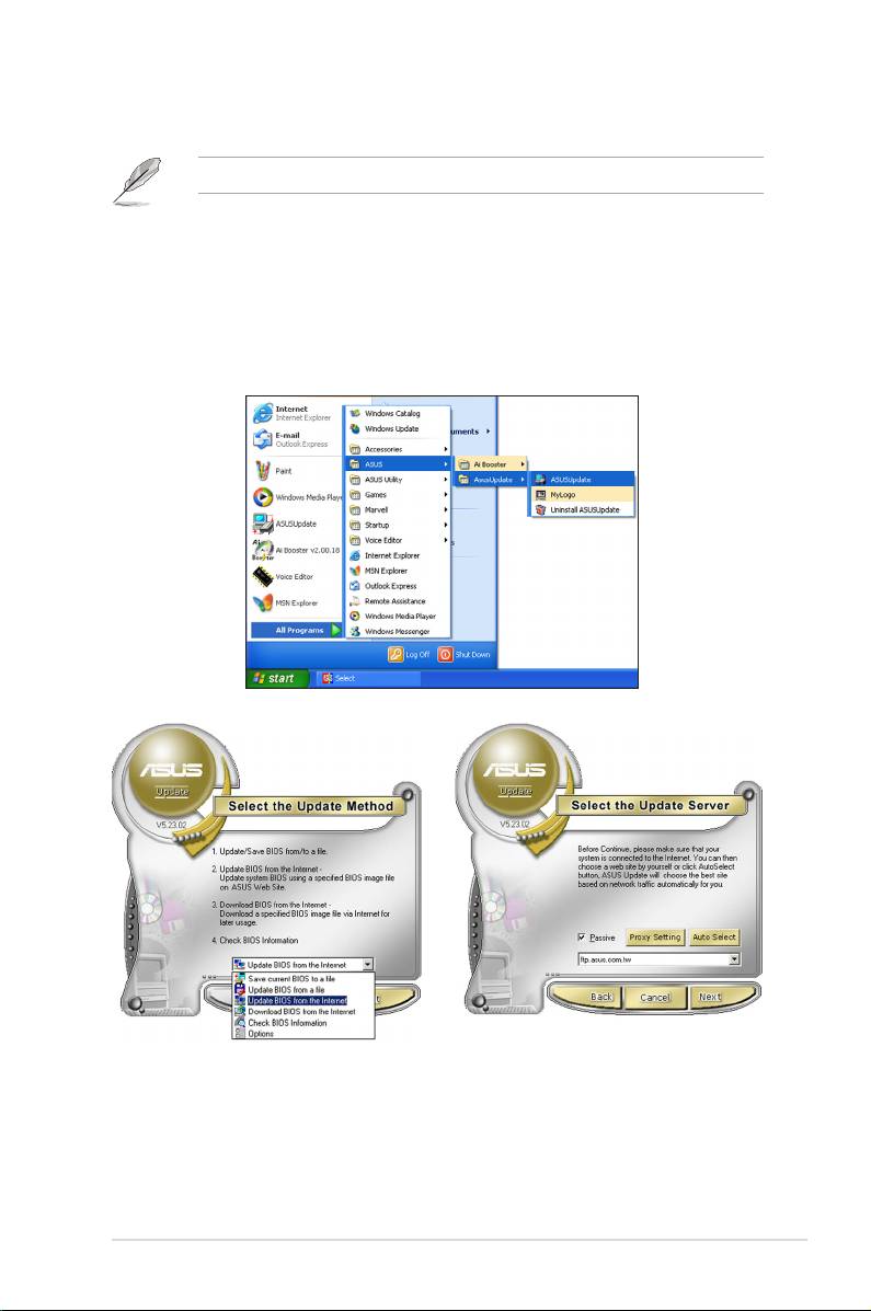
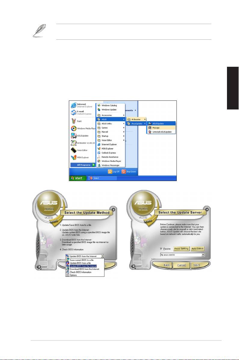
Updating the BIOS through the Internet
To update the BIOS through the Internet:
®
1. To aunch the ASUS Update utility from the Windows
desktop, click Start >
Programs > ASUS > ASUSUpdate > ASUSUpdate. The ASUS Update main
window appears.
2. Select Update BIOS from the
3. Select the ASUS FTP site nearest
drop‑down menu list, then click
you to avoid network trafc, or
Next.
click Auto Select. Click Next.
ASUS Motherboard installation guide 35
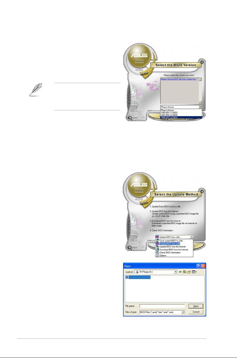
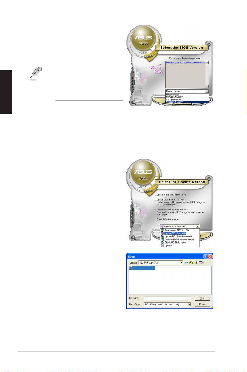
4. From the FTP site, select the BIOS
version that you wish to download.
Click Next.
5. Follow the screen instructions to
complete the update process.
The ASUS Update utility is
capable of updating itself through
the Internet. Always update the
utility to avail of all its features.
Updating the BIOS through a BIOS le
To update the BIOS through a BIOS le:
®
1. To launch the ASUS Update utility from the Windows
desktop, click Start
> Programs > ASUS > ASUSUpdate > ASUSUpdate. The ASUS Update
main window appears.
2. Select Update BIOS from the
drop‑down menu list, then click Next.
3. Locate the BIOS le from the Open
window, then click Open.
P5K3 Deluxe
4. Follow the screen instructions to
complete the update process.
P5K3 Deluxe
36 Chapter 2: Manage/update BIOS
Chapter 3: Troubleshooting
3.1 Troubleshooting for Motherboard DIY
After assembling your own computer, you might encounter troubles in starting it up.
This chapter provides answers to some common questions about your PC before
entering the operating system. Read this chapter for basic troubleshooting. It saves
time and hassles for you on contacting ASUS technical support team or returning
the product for warranty service.
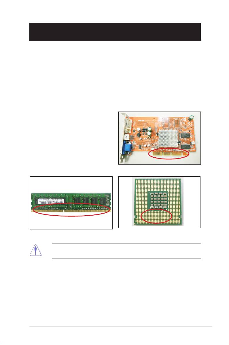
3.1.1 Basic troubleshooting
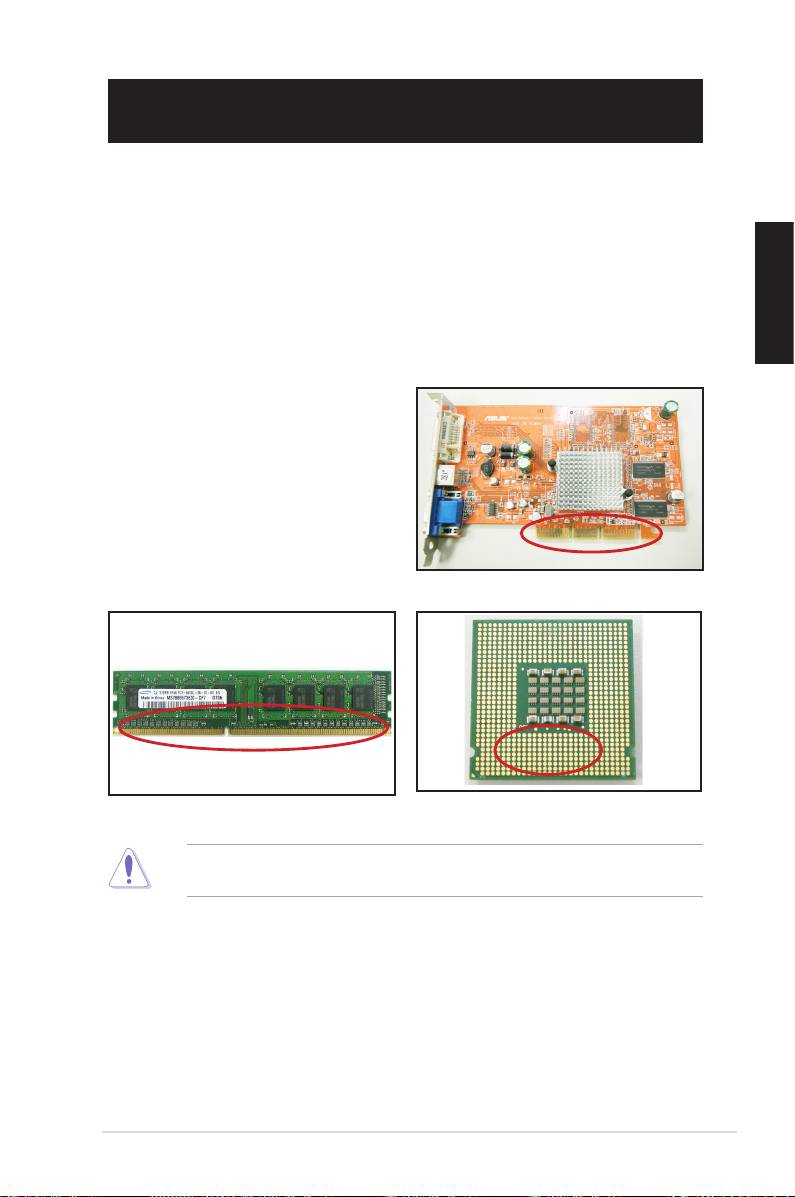
A. Bad connection
1. Ensure there is no contaminants on
the gold contact or the pins.
2. Use a cotton bud or an eraser
and gently rub the gold contact.
Remember to brush away the eraser
crumbs.
VGA card gold contact
DIMM gold contact
LGA775 processor gold contact points
Handle the card or the CPU by its edges and DO NOT touch the gold contact.
Static electricity will seriously damage the device.
ASUS Motherboard installation guide 37
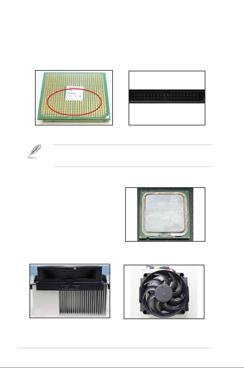
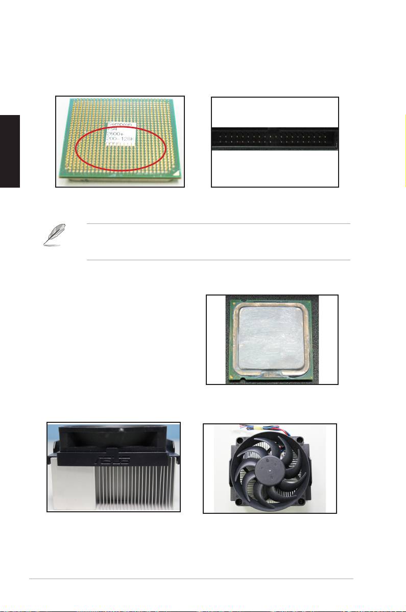
3. Ensure there is no broken or bended pins on your connector pins or CPU
pins. A broken and bended pin will cause the component malfunction.
Contact your retailer for further support.
AMD CPU gold pins
Connector pins
If the broken or bended pins are caused after the purchase, your retailer
may ask for repair charge. Sometimes the broken or bended pins are NOT
REPAIRABLE.
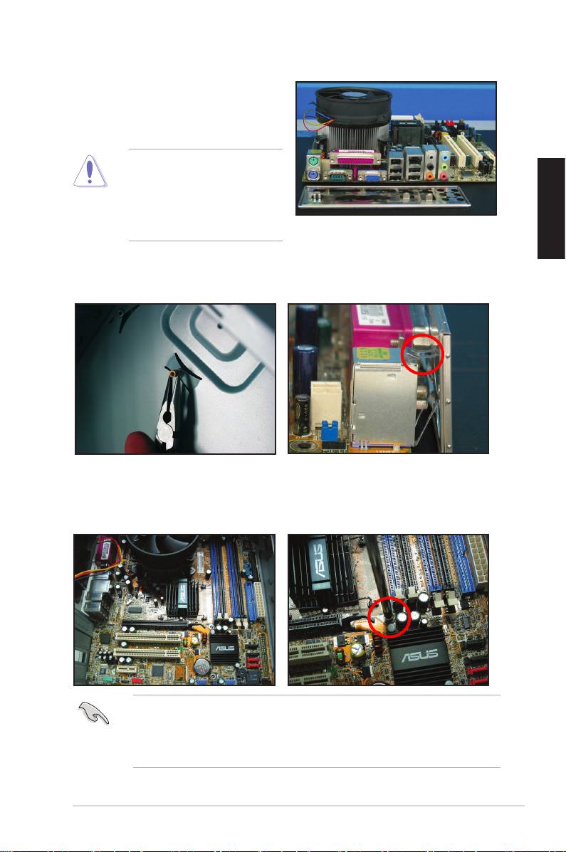
B. CPU overheated
1. Wipe clean the CPU surface with the
clean cloth. Apply several drops of
thermal paste to the exposed area of
the CPU that the heatsink will be in
contact with. Ensure that it is spread
in an even thin layer.
CPU surface
2. Ensure there is no contaminants on the heatsink and fan.
Side view of heatsink and fan
Top view of heatsink and fan
3. Follow the instructions of heatsink and fan manufacturers to clean the
contaminants that will slow down the fan rotation.
38 Chapter 3: Troubleshooting
3.2 Other common troubles
• When removing devices from the system, ensure all the power cables are
unplugged.
• All the error messages will be displayed on screen during the Power‑On Self‑
Test (POST).
• If there are BIOS beeps, refer to section 1.11 for details.
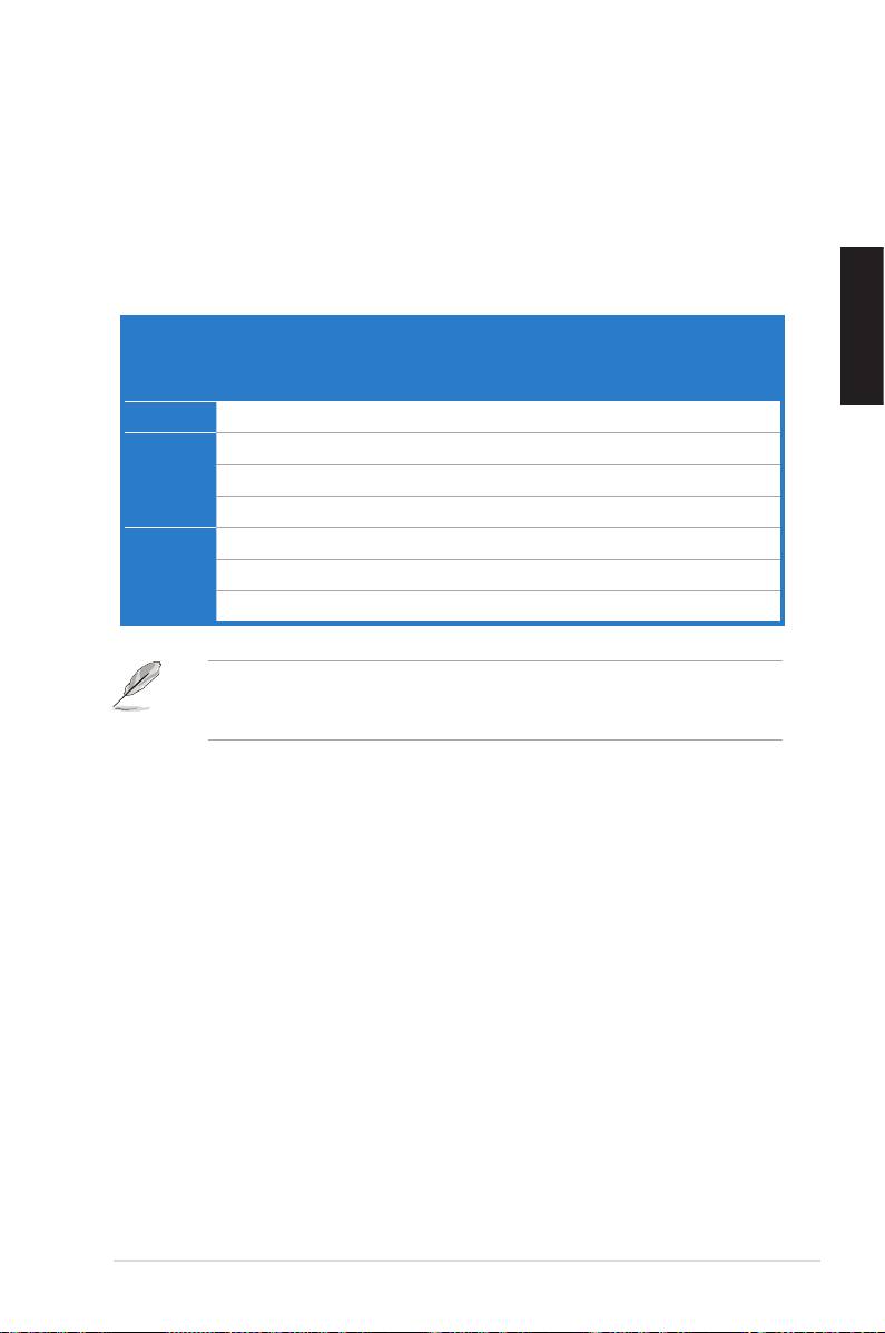
• Go over the checklist table below for further check.
Check Items
Power
Screen
Heatsink
BIOS
Error
Reference
LED
display
and fan
beeps
messages
page
No power Off No Stop No N/A 3‑4
No
On No Stop No N/A 3‑5
screen
On No Running No N/A 3‑5
display
On No Running Yes N//A 3‑5
Failure to
On Yes Running Yes Yes 3‑5
enter OS
On Yes Running No Yes 3‑5
On Yes Running No No 3‑5
If the problem has been xed but a new problem emerges, go over the checklist
again. If the problem persists, contact your retailer or ASUS technical support
team for further help.
ASUS Motherboard installation guide 39
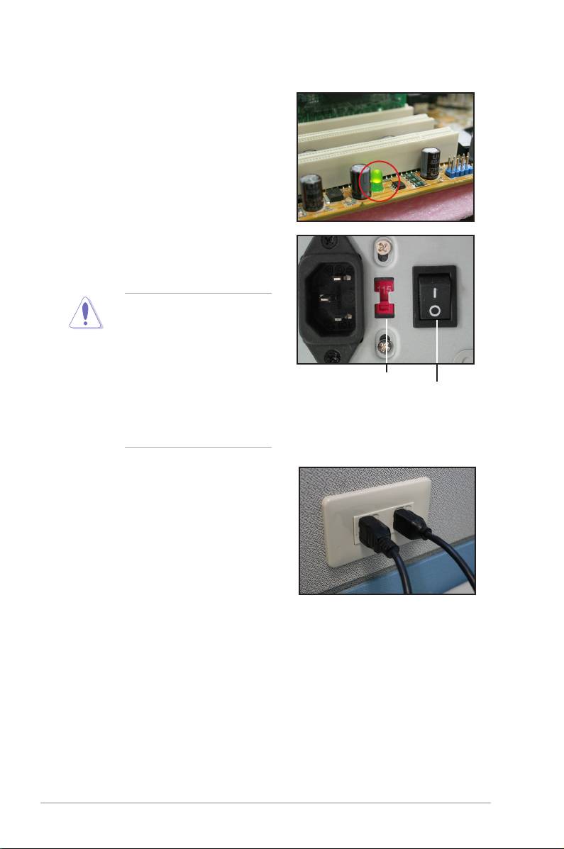
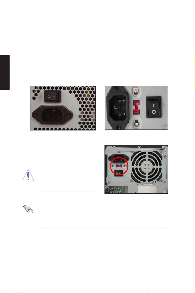
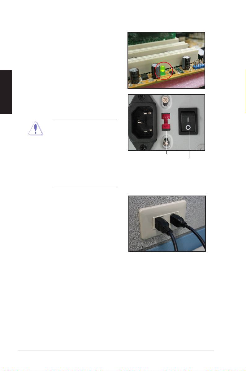
3.2.1 No power
ASUS motherboards come with a standby
power LED. The LED lights up to indicate
that the system is ON. If the LED stays
unlit, follow the instructions below to x
the problem.
1. Ensure to adjust your power supply
to the correct AC input voltage in
your area, and the power supply is
turned on.
• Before adjusting the AC
input voltage, ensure to
disconnect the power
plug. Failure to do so will
seriously damage the
power supply unit.
AC input voltage switch
Power switch
• Failure to adjust the power
“—”: On; “O”: Off
supply to the correct AC
input voltage will seriously
damage the system.
2. Ensure you have attached the
power cord to the wall outlet.
• Connect the power plug
directly to the wall outlet. DO
NOT connect it to the power
extension, uninterruptible
power supply (UPS) or other
devices.
• Exchange the power plugs of
the system and the monitor to
check whether the wall outlet is
working normally.
3. If the problem persists, you may need to contact your retailer for a new
power supply unit. If the power supply unit functions, contact your ASUS
motherboard retailer for motherboard warranty service.
40 Chapter 3: Troubleshooting

3.2.2 Failure to boot-up; No screen display
Most boot‑up failure and no screen display result from device defection or incorrect
installation. Follow the instructions below to x the problem.
1. Ensure that all the power cables are attached, including the system and the
monitor.
2. Ensure if the problem comes from expansion devices.
• Remove all the expansion card and devices. Use only motherboard,
monitor, VGA card, memory modules, power supply unit, heatsink and
fan, keyboard, and mouse to reboot the system.
• If the system is working normally, it is one of the expansion devices that
causes the problem. Reinstall the expansion devices you removed back
to the system one by one and nd out the defective device.
3. Ensure if the problem comes from the basic system devices.
• If you have some spare devices, you can replace the devices in turn
to nd out the defective device in the order of “memory module, CPU,
motherboard, hard/optical disk drive, keyboard/mouse.”
When you nd out the defective device, contact your device retailer for service.
3.2.3 Failure to enter the operating system
1. If the problem emerges after you add a hardware, remove the newly added
hardware and reboot the system. If the system is working normally without
the hardware, the device may be defective or incompatible with the system.
Contact the device retailer for help.
2. If the problem emerges after you install a software or driver, follow the
instructions below to x the problem.
a. Enter the operating system in safe mode and remove the software or
driver.
b. Contact the operating system company for further support.
c. If the previous instructions fail to x the problem, you may need to
reformat your hard disk drive and reinstall a new operating system.
3. If the problem emerges after you change the BIOS settings, reboot and enter
the BIOS to load the setup defaults. Refer the motherboard user guide for
details.
ASUS Motherboard installation guide 41

4. If the problem comes from a computer virus or a corrupt le, follow the
instructions below to x the problem.
a. Enter the operating system in safe mode and do a full system virus scan
using an anti‑virus application.
b. Contact the operating system company for further support.
c. If the previous instructions fail to x the problem, you may need to
reformat your hard disk drive and reinstall a new operating system.
3.2.4 FAQs
Q1: The memory reported in POST is different from the memory installed.
A1: The reported difference in memory may result from defective memory
modules or incorrect DIMM installation. Ensure the DIMMs are in good
condition and the DIMMs are installed correctly. Refer to the motherboard
user guide for details. If you install 4.0 GB memory and it reports 3.X GB, it is
normal.
Q2. The system cannot detect the oppy disk drive, but the oopy disk stays lit.
A2: The oopy disk cables are not properly installed. Ensure the red stripe on the
cable (pin1 end) should match pin1 on the oppy disk drive.
Q3: Fail to enter the operating system after the USB ash disk or external hard
disk drives.
A3: When the system detects USB ash disk or USB interface hard disks, it may
change the booting device priority. Remove the USB devices and restart the
system.
Q4: When installing Windows XP, it fails to locate the hard disk drives installed to
the RAID controller.
A4: Windows XP does not include the RAID controller driver so the hard disk
drives are not detected. Copy the RAID controller driver to a oppy disk and
when booting the system with the Windows XP disk, press <F6> to read the
driver from the oppy disk. Refer to the motherboard user guide for details.
42 Chapter 3: Troubleshooting

Chapter 4: Computer care tips
4.1 Proper care of your PC
Your personal computer is like other home appliances. Keep your computer
away from humidity, direct sun, and static electricity source. You should not move
the computer when it is turned on in case of damage. Internal dust will affect
the operating disk drive and contribute to overheating problem which will cause
computer crash or damage the components.
4.2 Basic knowledge
1. Encase your computer with dust cover when not in use.
2. When using your computer, do not put anything on the monitor to block the
ventilation holes. Excessive heat will cause the monitor malfunction.
3. Do not place the computer close to the wall and leave some space for heat
dissipation. Overheating will cause the system crash.
4. Place the computer on a stable surface.
5. Keep the computer away from areas of extreme temperature. 5°C to 30°C is
the best surroundings temperature. Use an air conditioner or a electric fan to
gain a better heat dissipation.
6. Arrange the ribbon cables neatly to avoid insufcient airow.
4.3 Usage knowledge
1. Turn on and shut down your computer regularly. If your computer needs to
be on for a long time, use a better system/CPU fan and high voltage power
supply unit.
2. A sudden power failure will damage the hard disk drive. When the power
supply is unstable, add an uninterruptible power supply to your computer is
recommended.
3. Rearrange the data les, do the virus scanning and virus codes renewal and
defragment disk regularly.
4. Clean your computer regularly. (Unplugged all the power cords before
cleaning)
• Uninstall the motherboad and hard/optical disk drives, then clean them
with canned air or a soft brush.
• Remove the dust and hair debris on the power supply unit with an anti‑
static vacuum.
ASUS Motherboard installation guide 43

4.4 Tips
1. If your computer will not be used for a long time, put some desiccant moisture
absorbers in the chassis to prevent humidity damage.
2. In some hot and humid climatic areas, you had better turn on your computer
every other week. Doing so also helps prevent humidity damage.
44 Chapter 4: Computer care tip

4.4 Tips
44 Computer care tip

Anakart
kurulumkılavuzu
Motherboard

TR4973
August 2009
Telif Hakkı © 2009 ASUSTeK COMPUTER INC. Tüm hakları saklıdır.
Türkçe
Bu el kitabının hiçbir bölümü, onun içinde tanımlanan yazılım ve de ürünler
de dahil olmak üzere, ASUSTeK COMPUTER INC. (“ASUS”) rmasının
açık bir biçimde yazılı izni olmaksızın, satın alan kişi tarafından yedek-
leme amaçlı olarak tutulan dokümantasyon haricinde yeniden üretilemez,
aktarılamaz, kopya edilemez, bir bilgi işlem sistemi içinde depolanamaz, ya
da her hangi bir şekilde ya da hiçbir biçimde hiçbir dile tercüme edilemez.
Aş
ğ
ıdaki şartlarda ürün garantisi ya da hizmeti uzatılmayacaktır: (1) ürünün
ASUS tarafından yazılı bir izin olmaksızın onarılması veya de
ği
ştirilmesi ya
da (2) ürünün seri numarasının tahrif edilmesi ve kaybolmas.
ASUS BU EL KİTABINI, BELİRLİ BİR AMAÇ İÇİN TİCARETE
ELVERİŞLİ NİTELİĞİN YA UYGUNLUĞUN ZIMNİ GARANTİLER
YA DA KOŞULLARI DA DAHİL OLMAK ÜZERE YA DA BUNLARLA
SINIRLI OLMAMAK KAYDIYLAYA AÇIK BİR ŞEKİLDE YA DA ZIM-
NEN HER HANGİ BİR TÜRÜN GARANTİSİ OLMAKSIZIN “OLDUĞU
GİBİ” SAĞLAR. HİÇBİR DURUMDA ASUS, ONUN DİREKTÖRLERİ,
MEMURLARI, ÇALIŞANLARI YA DA ACENTELERİ, BU EL KİTABI
YA DA ÜRÜN İÇERİSNDE HER HANGİ BİR KUSUR YA DA HATADAN
DOĞAN BU TÜR ZARARLARIN MEYDANA GELME OLASILIĞINI
TAVSİYE ETMİŞ OLSA DAHİ, HER HANGİ BİR DOLAYLI, ÖZEL,
TESADÜFİ YA DA SONUÇSAL ZARARLARDAN ( KAR KAYIPLA-
RI, İŞ KAYBI, KULLANIM YA DA VERİ KAYBI, İŞİN KESİNTİYE
UĞRAMASI VE DE BENZERİ GİBİ ZARARLAR DA DAHİL OLMAK
ÜZERE ) ÖTÜRÜ SORUMLU TUTULAMAZ.
BU EL KİTABI İÇİNDE YER ALAN SPESİFİKASYONLAR
VE DE BİLGİ SADECE BİLGİLENDİRME AMAÇLI OLARAK
TEDARİK EDİLMİŞTİR VE DE HER HANGİ BİR BİLDİRİMDE
B U L KU N U LM A K S IN I N H E R HA N G İ B İ R Z A M AN D A
DEĞİŞTİRİLMEYE TABİİDİR, VE DE ASUS TARAFINDAN BİR TAAH-
HÜT ŞEKLİNDE YOURMLANAMAZ. ASUS BU EL KİTABINDA VE
DE ONUN İÇİNDE TANIMLANAN YAZILIM VE DE ÜRÜNLERDE DE
DAHİL OLMAK ÜZERE GÖRÜNEN HER HANGİ BİR HATA YA DA
KUSURLARDAN ÖTÜRÜ HİÇBİR YÜKÜMLÜLÜK YA DA SORUM-
LULUK ÜSTLENMEZ.
Bu el kitabı içinde görünen ürünler ve de kurum isimleri, onların şirketlerinin
tescilli ticari markaları ya da telif hakları olabilir ya da olmayabilir ve de
ihlal amaçlı olmaksızın sadece tanıtım ya da açıklama amaçlı olarak ve de
mal sahibinin yararına kullanılmaktadır.
46

Güvenlik bilgileri
Elektriksel güvenlik
Türkçe
Çalıştırma güvenliği
47
Bölüm 1: Hızlı Çalıştırma
1.1 CPU Montajı
1.1.1 Intel LGA775 Soket
Türkçe
tespit edin.
Soket pinlerine hasar gelmesini
önlemek için CPU kurulumu
Kaldır-Yerleştir Başlığı (PnP Başlığı)
48
Türkçe
itin.
konektörlerin bükülmesini ve
CPU’nun hasar görmesini
1.1.2 Intel LGA1366 Yuvası
Tutma çıkıntısı
A
B
sola (B) hareket ettirin.
Yük kolu
önlemek için, bir CPU takana
Yük levhası
4
3
49
Türkçe
Altın
Üçgen
işareti
PnP kapağı
CPU çentiği
Hizalama anahtarı
A
oturana kadar ittirin.
B
50
1.1.3 Intel LGA1156 Socket
To prevent damage to the socket
pins, do not remove the PnP cap
Türkçe
51
A
B
Load lever
thumb (A), and then move it to the
right (B) until it is released from the
retention tab.
Retention tab
4. Remove the PnP cap from the
of the arrow until the load plate is
CPU socket.
PnP cap
Load plate
5. Position the CPU over the socket,
ensuring that the gold triangle is on
the bottom-left corner of the socket,
CPU notches
CPU into the socket to prevent
Gold
triangle
bending the connectors on the
mark
socket and damaging the CPU!
Alignment keys
Türkçe
7. Close the load plate (A), and
then push down the load lever
(B), ensuring that the front edge
of the load plate slides under the
retention lock (C).
52
B
A
C
Material to the exposed area of
the CPU that the heatsink will be
in contact with, ensuring that it is
Some heatsinks come with
pre-applied thermal paste. If
so, skip this step.
The Thermal Interface Material
professional medical help.
8. Insert the load lever under the
retention tab.
Türkçe
53
A
B
1.1.3 Intel LGA1156 Soketi
1. Anakarttaki CPU soketini bulun.
Yükleme kolu
Soket pinlerinin hasar görmesini
Muhafaza tırnağı
PnP başlığı
Yük
levhası
CPU çentikleri
Altın
bükülmesini ve CPU'nun
üçgen
hasar görmesini önlemek için
işareti
Hizalama
anahtarları

Türkçe
54
B
A
C
1.1.4 AMD AM2 Yuvası
Türkçe
oturur.
55
1.2 Isı emici ve fan montajı
Türkçe
Intel sertikalı ısı emici için:
macunla birlikte gelir. Bu durumda
56
B
A
A
B
Türkçe
AMD sertikalı ısı emici için:
1
2
3
4
57
1.3 DIMM takma
Çift klipsli bir DIMM soketine bir DIMM takma
2
Türkçe
DIMM çentiği
1
1
Kilidi açılmış tutucu klips
Kilitli Tutucu Klips
Tek klipsli bir DIMM soketine bir DIMM takma
2
DIMM çentiği
1
Kilidi açılmış tutucu klips
Kilitli Tutucu Klips
58
1.4 Anakart montajı
paketi ile birlikte gelen arka I/O
Türkçe
edin.
dikkatli olun.
59
1.5 Güç kaynağı ünitesi montajı
Aktif PFC’li güç kaynağı:
Pasif PFC’li güç kaynağı:
Türkçe
verir.
müracaat edin.
60
1.6 Genişletme kartı montajı
Türkçe
PCI kartı PCIE x16 kartı
PCIE x1 kartı
61
1.7 Disk sürücülerinin montajı
1.7.1 PATA optik disk sürücüsü
disk sürücüsünü vidalarla
Türkçe
pin1 ucudur ve optik sürücüdeki
gelmelidir.
4. 4 pinli güç kablosunu optik
5. Ses kablosunu optik sürücüdeki
62
1.7.2 SATA optik disk sürücüsü
disk sürücüsünü vidalarla
Türkçe
5. Ses kablosunu optik sürücüdeki
63
1.7.3 Disket sürücü
Türkçe
64
1.7.4 PATA sabit disk sürücü
Türkçe
4. 4 pinli güç kablosunu sabit disk
65
PATA sabit disk sürücü montajı ile ilgili notlar
Türkçe
• Kablolar çekme uçlu olarak
sadece kablo etiketlerine göre
Pinlere hasar gelmesini önlemek
çekerek kesin.
ATA66/100/133 disk sürücüler
için sadece 80-telli kablo daha
kablolar genellikle optik sürücüler
içindir.
• Kablo konnektörü renk kodludur.
Mavi olan ana konnektördür,
sürücü içindir.
66
1.7.5 SATA sabit disk sürücü
Türkçe
4. SATA güç kablosunu sabit disk
oturabilir.
SATA sabit disk sürücü montajı ile ilgili notlar
• SATA güç kablosu konnektörü
geleneksel 4 pinli güç
kablolama ile ilgili meselelere
konnektörü içermemesi durumunda
67
1.8 Ön panel kabloları
Türkçe
68
M2N-X
Reset
ANE
RESET
PLED SPEAKER
P5B-E
PLED+
PLED-
+5V
Ground
Ground
Speaker
®
PANEL
PWR
Reset
Ground
Ground
IDE_LED+
IDE_LED-
IDE_LED
RESET
PWRSW
*
Requires an ATX power supply.
20-8 pinli ön panel konnektörü
PIN1
PIN1
10-1 pinli ön panel konnektörü
ASUS Q-Konnektör
müracaat edin.
Türkçe
1.9 ATX gücünün bağlanması
20 pinli güç konnektörü
24 pinli güç konnektörü
(24 pinli dişi karşılığında)
4 pinli güç konnektörü
69
Türkçe
Güç konnektörleri
20+4 (24) pin ATX konnektör
4 pinli ATX konnektör
çevre birim güç konnektörü (sol)
disket güç konektörü (sağ)
70
1.10 Çevre birimleri ve aksesuarlar
1. AC güç şi
8. PS/2 fare
portu
2. PS/2 klavye
9. Paralel port
portu
3. S/PDIF çıkış
10. IEEE1394 portu
Türkçe
portu
4. Seri port
11. LAN (RJ45)
portu
5. USB portu
12. Hat giriş
portu
13. Video grak
6. Mikrofon portu
adaptör portu
7. Hat çıkış portu 14. DVI portu
kablosu
5.1 hoparlör sistemi
sabit disk sürücü
71
1.11 İlk kez çalıştırma
BIOS Bip Sesi Açıklama
sesi
Türkçe
bip sesi
(AMI BIOS)
Sorun Giderme
Sorun Eylem
emin olun.
Slave)
kontrol edin.
72
Bölüm 2: BIOS Yönetme/güncelleme
2.1 AFUDOSprogramı
Mevcut BIOS’un Kopyalanması
Türkçe
afudos /o[dosya adı]
A:\>afudos /oOLDBIOS1.rom
Ana dosya adı Uzatma adı
A:\>afudos /oOLDBIOS1.rom
AMI Firmware Update Utility - Version 1.19(ASUS V2.07(03.11.24BB))
Copyright (C) 2002 American Megatrends, Inc. All rights reserved.
Reading ash ..... done
Write to le...... ok
A:\>
BIOS dosyasının güncellenmesi
73
afudos /i[dosya adı]
Türkçe
A:\>afudos /iP5K3D.ROM
A:\>afudos /iP5K3D.ROM
AMI Firmware Update Utility - Version 1.19(ASUS V2.07(03.11.24BB))
Copyright (C) 2002 American Megatrends, Inc. All rights reserved.
WARNING!! Do not turn off power during ash BIOS
Reading le ....... done
Reading ash ...... done
Advance Check ......
Erasing ash ...... done
Writing ash ...... 0x0008CC00 (9%)
A:\>afudos /iP5K3D.ROM
AMI Firmware Update Utility - Version 1.19(ASUS V2.07(03.11.24BB))
Copyright (C) 2002 American Megatrends, Inc. All rights reserved.
WARNING!! Do not turn off power during ash BIOS
Reading le ....... done
Reading ash ...... done
Advance Check ......
Erasing ash ...... done
Writing ash ...... done
Verifying ash .... done
Please restart your computer
A:\>
74
2.2 Award BIOS Flash Programı
BIOS güncelleme
FAT 16/12 biçimindeki
Türkçe
AwardBIOS Flash Utility for ASUS V1.14
(C) Phoenix Technologies Ltd. All Rights Reserved
gösterir) kullanarak
For NF590-SLI-M2N32-SLI-DELUXE DATE:03/30/2006
Flash Type - PMC Pm49FL004T LPC/FWH
File Name to Program:
diskinin ve Award BIOS
klasörüne geçin.
Message: Please input File Name!
75
AwardBIOS Flash Utility for ASUS V1.14
(C) Phoenix Technologies Ltd. All Rights Reserved
For NF590-SLI-M2N32-SLI-DELUXE DATE:03/30/2006
Flash Type - PMC Pm49FL004T LPC/FWH
File Name to Program: M2N32SLI.bin
Türkçe
Message: Do You Want To Save Bios (Y/N)
AwardBIOS Flash Utility for ASUS V1.14
(C) Phoenix Technologies Ltd. All Rights Reserved
For NF590-SLI-M2N32-SLI-DELUXE DATE:03/30/2006
Flash Type - PMC Pm49FL004T LPC/FWH
File Name to Program: M2N32SLI.bin
Programming Flash Memory - OFE00 OK
Write OK No Update Write Fail
Warning: Don’t Turn Off Power Or Reset System!
AwardBIOS Flash Utility for ASUS V1.14
(C) Phoenix Technologies Ltd. All Rights Reserved
For NF590-SLI-M2N32-SLI-DELUXE DATE:03/30/2006
Flash Type - PMC Pm49FL004T LPC/FWH
File Name to Program: M2N32SLI.bin
Flashing Complete
Press <F1> to Continue
Write OK No Update Write Fail
F1
Reset
76
Mevcut BIOS dosyasının kaydedilmesi
1. Önceki ekrandaki 1.
AwardBIOS Flash Utility for ASUS V1.14
Türkçe
(C) Phoenix Technologies Ltd. All Rights Reserved
For NF590-SLI-M2N32-SLI-DELUXE DATE:03/30/2006
Flash Type - PMC Pm49FL004T LPC/FWH
2. Program mevcut BIOS
File Name to Program: 0112.bin
Save current BIOS as:
belirir.
Message:
AwardBIOS Flash Utility for ASUS V1.14
(C) Phoenix Technologies Ltd. All Rights Reserved
For NF590-SLI-M2N32-SLI-DELUXE DATE:03/30/2006
Flash Type - PMC Pm49FL004T LPC/FWH
File Name to Program: 0112.bin
Checksum: 810DH
Save current BIOS as: 0113.bin
Message: Please Wait!
4. Program mevcut BIOS
AwardBIOS Flash Utility for ASUS V1.14
(C) Phoenix Technologies Ltd. All Rights Reserved
For NF590-SLI-M2N32-SLI-DELUXE DATE:03/30/2006
Flash Type - PMC Pm49FL004T LPC/FWH
File Name to Program: 0113.bin
Now Backup System BIOS to
File!
Message: Please Wait!
77

2.3 ASUSGüncellemeprogramı
®
Türkçe
• BIOS sürüm bilgilerinin görüntülenmesi.
ASUS Güncellemesinin Kurulması
Sürücüler menüsü belirir.
2. ProgramlarASUS Güncellemesini Kur’a
78
®
BIOS’un internetten güncellenmesi
1. Başlat > Programlar > ASUS > ASUSUpdate > ASUSUpdate
®
Türkçe
BIOS’u
İnternetten Güncelle
İleri
Oto Seçİleri
79
BIOS sürümünü seçin. İleri
Türkçe
BIOS’un BIOS dosyasından güncelleme
1. Başlat > Programlar > ASUS > ASUSUpdate > ASUSUpdate
®
BIOS’u
Dosyadan Güncelle
İleri
Açık pencereden
Aç
P5K3 Deluxe
getirin.
P5K3 Deluxe
80
Bölüm 3: Sorun Giderme
3.1 Anakart DIY için Sorun Giderme
Türkçe
3.1.1 Temel sorun giderme
A. Kötü bağlantı
VGA kartı altın kontak
DIMM altın kontak
LGA775 işlemci altın kontak noktaları
81
Türkçe
AMD CPU altın pinler
Konektör pinleri
B. CPU’nun aşırı ısınması
CPU yüzeyi
Isı emici ve fan yan görünümü
Isı emici ve fan üst görünümü
82
3.2 Diğer yaygın sorunlar
emin olun.
gösterilecektir.
Kontrol öğeleri
Türkçe
Güç LED’i Ekran
Isı emici
BIOS Bip
Hata
Referans
göstergesi
ve fan
Sesleri
mesajları
sayfa
Güç yok N/A 3-4
Ekran
N/A 3-5
göstergesi
N/A 3-5
yok
Evet N//A 3-5
İşletim
Evet Evet Evet 3-5
Sistemine
Evet Evet 3-5
Giriş
Başarısız
Evet 3-5
destek ekibi ile temasa geçin.
83
3.2.1 Güç yok
Türkçe
emin olun.
AC giriş voltaj düğmesi
Güç düğmesi
“—”: Açık;
“O”: Kapalı
• Sistem ve monitöre ait güç
84

3.2.2 Ön yükleme başarısız; Görüntü yok
olun.
Türkçe
olun.
3.2.3 İşletim sistemine giriş başarısız
ile temasa geçin.
gerekebilir.
85

Türkçe
gerekebilir.
3.2.4 Sıkça Sorulan Sorular
normaldir.
86

Bölüm 4: Bilgisayar bakımı ile ilgili ipuçları
4.1 Bilgisayarınızın uygun bakımı
4.2 Temel bilgiler
Türkçe
4.3 Kullanım bilgileri
4.4 İpuçları
87

Türkçe
88
