Thermon ECM-R-XP: инструкция
Раздел: Профоборудование
Тип: Аппарат
Инструкция к Аппарату Thermon ECM-R-XP
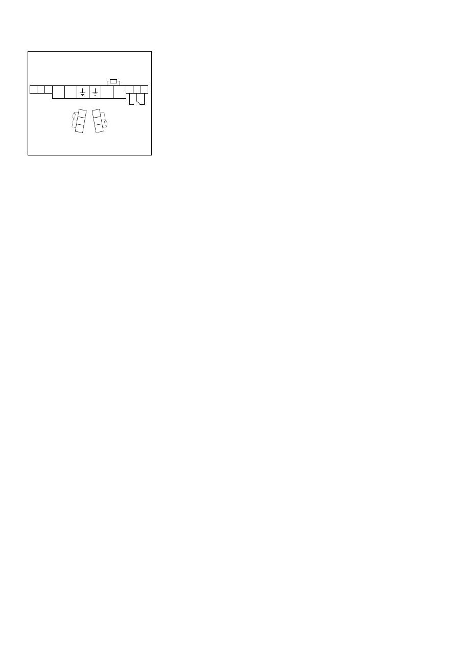
1725 II 2 GD Ex eb mb [ib]ib IIC T4, Ex tb IIIC T135°C
SIRA 12ATEX5239X
IP66
-60
°
C
≤
Ta
≤
+ 55
°
C
IECEx SIR 12.0103X Ex eb mb [ib]ib IIC T4, Ex tb IIIC T135°C
PN 27673
Do
no
t op
en w
hile energ
ized. See insta
llatio
n in
str
uc
tio
ns
.
Te
rmi
nator EC
M
Fo
r u
se
as
an a
djusta
ble electronic co
ntrol
mod
ule
The Heat Tracing Specialists
®
Terminator
TM
ECM-R-XP
Electronic Control Module
INSTALLATION PROCEDURES
For Use With TESH Series Constant Watt Heating
Cables
2
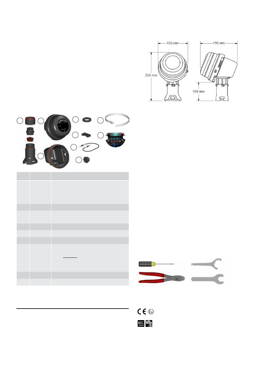
Tools Required . . .
Kit Contents . . .
1
2
6
4
3
8
5
7
9
Item Quantity
Description
1
1
Expediter Assembly
Support Cap with O-Ring
Threaded Grommet Compressor
Grommet
Support Base with O-Ring
2
1
Junction Box Lid
3
1
Junction Box Base with O-Ring & M25
Dust Cap
4
1
Nut
5
1
Banding
6
1
Banding Guide
7
1
Electronic Control Module w/ Terminal Blocks
(Refer to terminal specifications for maximum allowable wire size)
ECM Type*
C - Controler
L - Limiter
CL - Controller/Limiter
* The maximum pipe exposure temperature is limited to 250°C
8
1
Junction Box Lid Cord
9
3
Blind Plug
Terminator-LN-Tool
(order separately)
3 mm
8 mm
28 mm
Warnings . . .
• Due to the risk of electrical shock, arcing and fire
caused by product damage or improper usage,
installation or maintenance, a ground-fault protection
device is required.
• Installation must comply with Thermon requirements
(including form PN 50207U for Ex systems) and be
installed in accordance with the regulations as per the
norm EN IEC 60079-14 for hazardous areas (where
applicable), or any other applicable national and local
codes.
• Component approvals and performance ratings are
based on the use of Thermon specified parts only.
• De-energize all power sources before opening
enclosure.
• Avoid electrostatic charge. Clean only with a damp
cloth.
• Keep ends of heating cable and kit components dry
before and during installation.
• Minimum bending radius of heating cable is five (5)
times the cable outer diameter.
• Individuals installing these products are responsible
for complying with all applicable safety and health
guidelines. Proper Personal Protective Equipment
(PPE) should be utilized during installation. Contact
Thermon if you have any additional questions.
The following installation procedures are suggested
guidelines for the installation of the Terminator ECM-R-XP
Kit. For translations other than English and local language
translation provided here, please contact Thermon. The
English language installation procedure shall govern.
Receiving, Storing and Handling . . .
1. Inspect materials for damage incurred during shipping.
2. Report damages to the carrier for settlement.
3. Identify parts against the packing list to ensure the
proper type and quantity has been received.
4. Store in a dry location.
Dimensions . . .
Terminator
TM
ECM-R-XP
INSTALLATION PROCEDURES
1725
II 2 GD Ex eb mb [ib]ib I
IC T4, Ex tb I
IIC T135°C
S
IRA 12ATE
X5239X
IP66
-60
°
C
≤
Ta
≤
+ 55
°
C
IECEx SIR 12.0103X
Ex eb mb [ib]ib I
IC T4, Ex tb I
IIC T135°C
PN 27673
Do n
ot op
en while energized. See ins
talla
tio
n i
ns
tru
ct
io
ns
.
Te
rm
inator ECM
Fo
r u
se
as
an
a
djus
table
electronic c
ontrol
mod
ule
Crimp Tool 2,5mm
2
Order Separately . . .
PETK Power and End Termination Kits (per cable)
PETK-5
for direct connection
PETK-10
for cold lead connection (TESH 2.9-15)
PETK-11
for cold lead connection (TESH 17.8-8000)
Certifications/Approvals . . .
Ordinary & Hazardous Locations
International Electrotechnical Commission
IEC Certification Scheme for Explosive Atmospheres
SIR 12.0103X
II 2 (2) G Ex eb mb [ib] IIC T4, Ex tb IIIC T135°C SIRA 12ATEX5239X
II 2 (2) D Ex tb IIIC T135°C IP66 Db
3
Terminator
TM
ECM-R-XP
INSTALLATION PROCEDURES
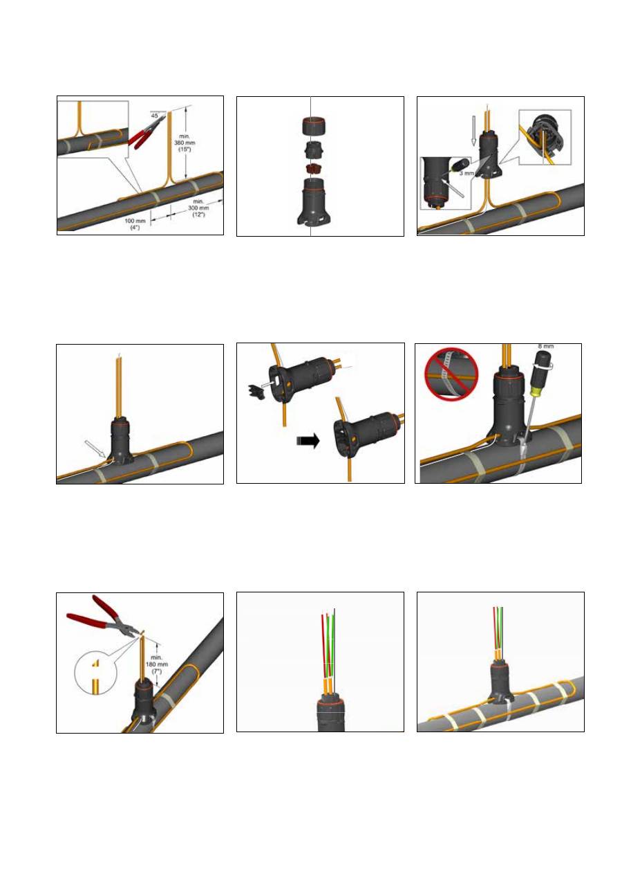
1.
Cut end of cable at angle to aid in piercing
grommet. Leave additional cable for
expansion loop.
5.
Insert banding guide into expediter and
snap into place.
3.
Insert cable into expediter. If mounted on
bottom or side of pipe, punch out weep hole.
4.
Slide expediter toward pipe and route
cable through support base entry.
6.
Mount expediter to pipe using pipe band.
Do not band over cable.
7.
Cut off end of cable.
2.
Position RTD Sensor(s) in grommet (when
applicable). Do not pull from the sensor
end when routing through the expediter
assembly. Pull sensor from the lead wire
portion.
8.
Terminate cable with appropriate PETK
termination kit. Refer to PETK installation
instructions.
9.
Push excess cable and RTD cable back
through expediter. Tighten cap securely.
Tape cable expansion loop to pipe.
Terminator
TM
ECM-R-XP
INSTALLATION PROCEDURES
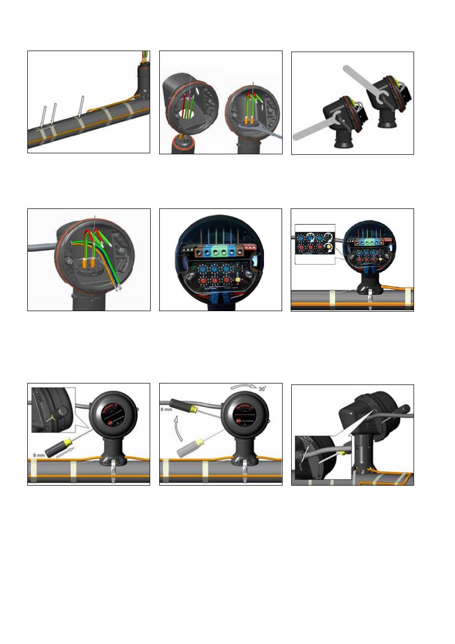
13.
Install power cable.
15.
Use the rotary switches for settling
Control and Limit Temperature,
(Celcius or Fahrenheit) and Auto or
Manual reset (Control switches on
Type "C", Limiter switches on Type
"L" and both on Type "CL").
14.
Install electronic control module and
complete system wiring. Terminal set
screws shall be tightened to a torque
value of 1,4 Nm (12,4 lb-in). See
wiring details. Set modules electronic
control and/or control limiter at desired
setpoints.
12.
Remove M25 dust cap. Install M25
power gland (order separately) and
M25 blind plug.
11.
Mount junction box base on expediter.
Make sure to align slots to properly
orient junction box base. Tighten nut
with Terminator-LN-Tool. If mounting
horizontally, threaded gland holes must
face downward.
10.
Fix expediter, RTD, and lead wire to pipe.
16.
Install junction box lid and twist hand
tight. Insert screwdriver into ratchet slots
located on side of junction box base.
17.
Use screwdriver to ratchet on junction
box lid. Lid will rotate 30 degrees.
18.
Lid latch mechanism fully engaged. To
remove lid, repeat steps 16 and 17 but
in the opposite direction.
Wiring Details
L
L
N
N
C
NO
NC
Comm. Port
Alarm Relay
Main supply
Heater output
B
B
A
A
B
B
RTD
Limiter Sensor
RTD
Controller Sensor
GND 1
2
Terminator
TM
ECM-R-XP
INSTALLATION PROCEDURES

Française
Terminator ECM-R-XP
Module de contrôle électronique
Procédures d'installation
Avertissement…
• En raison du risque de choc électrique, d'arc électrique et d'incendie
causés par des dommages au produit, à la mauvaise utilisation, ou
à la mauvaise installation, un dispositif de protection à courant de
défaut est nécessaire (disjoncteur différentiel).
• L'installation doit se conformer aux exigences Thermon (y compris la
notice PN 50207U pour les installations Ex) et doit être réalisée en
conformité avec les règlements, conformément à la norme EN CEI
60079-14 pour les zones dangereuses (le cas échéant), ou tout autre
code national ou local.
• Les approbations des composants et les évaluations de performance
sont basées uniquement sur l'utilisation des composants Thermon
spécifiés.
• Coupez l'alimentation de toutes les sources d'énergie avant d'ouvrir le
boîtier.
• Pour éviter les charges électrostatiques. Nettoyez uniquement avec
un chiffon humide.
• Gardez les extrémités des câbles et les composants au sec avant et
pendant l'installation.
• Le rayon de courbure minimum du câble de chauffage est de 32 mm
(à l'exception des câbles HPT, rayon minimum 57 mm et des câbles
FP rayon minimum 19 mm.
• Les personnes installant ces produits sont responsables pour la
conformité avec toutes les normes applicables et les directives
d'hygiène et de santé. Un équipement de protection individuelle (EPI)
doivent être utilisé lors de l'installation. Contactez Thermon si vous
avez des questions supplémentaires.
1. Coupez l'extrémité du câble en pointe pour aider à percer la bague
d'étanchéité. Laissez une longueur de câble supplémentaire pour la
lyre de dilatation.
2. Passez la sonde du RTD par le joint (si applicable). Ne pas tirer
depuis le côté de la sonde, pour passer l'ensemble dans le pied
"expeditor" de la boîte de jonction. Tirez la sonde depuis l'autre
extêmité, soit la partie de câble.
3. Insérez le câble dans le pied "EXPEDITER" de la boîte de jonction.
S' il est monté sur le bas ou sur le côté du tuyau, utilisez les trous pré
formés de la boîte de jontion.
4. Faites glisser le pied support vers le tuyau et passez le câble par la
base du pied de la boîte de jonction.
5. Insérez le guide de cerclage dans le pied support et mettre en
place.
6. Fixez le pied support sur le tuyau à l'aide du collier de fixation. Ne
pas coincer le câble chauffant avec le collier.
7. Coupez l'extrémité du câble.
8. Terminez le câble à l'aide des kits de terminaison PETK appropriés.
Reportez-vous aux inst ructions d'installation des PETK.
9. Montez le pied du terminator sur le tuyau à l'aide de la bande
de fixation. Ne pas plier le ruban chauffant. Si nécessaire, fixez
temporairement la base de la boîte de jonction sur le pied du
terminator.
10. Repoussez l'excédent de câble en arrière à travers le pied support.
Faire avec ce câble, une lyre d'expansion sur le tuyau. Serrer le
couvercle.
11. Fixez le pied support, la sonde RTD, et le câble au tuyau.
12. Placez la base de la boîte de jonction sur le pied support. Veillez à
aligner correctement les fentes de la base afin d'orienter le boîtier.
Serrez l'écrou à l'aide de l'outil LN-TOOL. En cas de montage à
l'horizontal les trous des presses étoupe doivent être orientés vers
le bas.
13. Installez le presse-étoupe M25 (à commander séparemment) et
le bouchon M25. Pour les jonctions en ligne, les dérivations en T,
ou les terminaisons, installez des bouchons M25 complémentaires
(Commande M25-B-EXE separée) à la place des presses étoupes
M25.
14. Installez le câble d'alimentation (si nécessaire).
15. I n s t a l l e z le module de contrôle électronique, et tout le système
de câble associé. Les visses sur les borniers doivent être serrées
suivant un couple de 1,4 Nm (12,4 lb-in). Voir page 5 pour le détail
du câblage. Réglez le module de contrôle et/ou le limiteur au point
souhaité.
16. Utilisez les boutons tournants pour régler la tempérautre soit de
contrôle soit du limiteur, Celcius ou Fahrenheit, auto ou manuel (
Bouton de contrôle, position "C", Bouton limiteur position "L", "CL"
pour les deux fonctions).
17. Positionnezle couvercle sur la boîte et visser le manuellement.
Glissez un tournevis dans les fentes situées sur la périphérie du
boîtier pour effectuer une rotation de 30 degrés environ jusqu'au
point de blocage.
Deutsch
Terminator ECM-R-XP
Elektronisches Regelmodul
INSTALLATIONSANWEISUNG
Warnhinweise…
• Wegen der Risiken eines Stromschlags, eines Funkendurchschlags
oder eines Feuers, die durch Produktbeschädigungen oder nicht
sachgerechte Nutzung, Installation oder Wartung verursacht werden
können, ist ein Fehlerstromschutzschalter erforderlich.
• Die Installation muss den Thermon-Vorgaben entsprechen
(einschließlich der Richtlinie PN 50207U für Ex-Systeme) und muss
in Übereinstimmung mit den Vorschriften gemäß der EN IEC 60079-
14-Norm für Gefahrbereiche (gegebenenfalls) sowie entsprechend
aller anderen anwendbaren nationalen und regionalen Vorgaben
eingebaut werden.
• Zulassungen und Angaben techn. Eigenschaften, beziehen sich
ausschießlich auf die Verwendung von Thermonspezifizierten Teilen.
• Vor dem Öffnen der Abdeckung müssen sämtliche Stromquellen
abgeschaltet werden.
• Vermeiden Sie elektrostatische Aufladungen. Verwenden Sie zur
Reinigung einen feuchten Lappen.
• Vor und während der Installation müssen die Enden der Heizkabel
und Bausatzkomponenten trocken sein.
• Der Minimumbiegeradius der Heizkabel beträgt 32 mm (Ausnahmen:
HPT - 57 mm und FP - 19 mm).
• Jeder, der diese Produkte installiert, ist für die Einhaltung aller
anwendbaren Sicherheits- und Gesundheitsrichtlinien verantwortlich.
Während des Einbaus sollte eine geeignete persönliche
Schutzausrüstung (PSA) getragen werden. Falls Sie weitere Fragen
haben, wenden Sie sich bitte an Thermon.
1. Schneiden Sie das Ende des Kabels schräg ab, um die Dichtung
leichter durchstossen zu können. Lassen Sie zusätzliche Kabellänge
für eine Ausdehnungsschleife.
2. Positionieren Sie den/die RTD-Sensor(-en) in einer Dichtung. Ziehen
Sie nicht am Sensorkopf wenn Sie ihn durch die Montagesäule
führen, sondern immer nur am Anschlusskabel.
3. Führen Sie das Kabel in die Montagesäule ein.
4. Führen Sie die Durchführung in Richtung Rohrleitung und das
Heizkabel durch die Bohrung im Gehäuseunterteil ein.
5. Spannbandführung in Säule einsetzen und darauf achten das diese
eingerastet ist.
6. Montagesäule mittels Spannband auf der Rohrleitung befestigen.
7. Kabelende abschneiden.
8. Kabelendabschluss mit den passenden PETK-Komponenten
erstellen. Halten Sie sich an die PETK-Installationsanweisungen.
9. Montagesäule mittels Spannband auf der Rohrleitung befestigen,
dabei nicht das Spannband über das Heizkabel montieren!
Erforderlichenfalls das Gehäuse- oberteil provisorisch montieren.
10. Überschüssiges Kabel durch die Säule zurückschieben;
Überwurfmutter fest anziehen; Heizkabelschleife am Rohr
befestigen.
11. Befestigen Sie die Montagesäule, den RTD und das Kabel am Rohr.
12. Thermostateinsatz ausbauen und das Unterteil des Klemmkastens
auf der Montagesäule befestigen. Dabei auf korrekte und
richtige Ausrichtung der Rastung achten. Befestigungsmutter
mit dem Terminator-LN-Schlüssel festziehen. Wenn die Einheit
horizontal montiert werden soll, so ist darauf zu achten das die
Verschraubungen nach unten zeigen.
13. Installieren Sie die M25-Einspeisekabelverschraubung (separat zu
bestellen) und den M25-Blindstopfen. Bei Verwendung als Spleiß/T-
Spleiß oder Endabschlussdose ist ein weiterer Blindstopfen anstelle
der Einspeisekabelverschraubung zu verwenden (separat zu
bestellen).
14. Einspeisekabel einführen.
15. Thermostateinsatz einsetzen und Verkabelung vervollständigen. Die
Schrauben sollten mit einem Drehmoment von 1,4 Nm (12,4 lb - in )
angezogen werden. Regler/Begrenzer auf gewünschte/ erforderliche
Temperaturen einstellen.
16. Verwenden Sie die Drehschalter, um die Regel- und
Begrenzertemperatur einzustellen. Anzeige in Celsius oder
Fahrenheit und automatische oder manuelle Rücksetzung
(Kontrollschalter auf Typ "C", Begrenzungsschalter auf Typ "L" und
für beide Optionen auf Typ "CL".
17. Den Deckel der Anschlussdose aufsetzen und handfest zudrehen.
Führen Sie nun einen Schraubendreher in die seitlichen Schlitze der
Anschlussdose ein und drehen Sie den Deckel um weitere ca. 30
Grad um ihn sicher zu verschliessen. Zum entfernen des Deckels
wiederholen Sie die Schritte in umgekehrter Reihenfolge.Tam mac

Русский
Термостат ECM-R-XP
Электронный модуль управления
ИНСТРУКЦИЯ ПО МОНТАЖУ
Для подключения (1-2 нагревательных кабелей)
Меры предосторожности…
• Во избежание риска поражения электрическим током, искрения
и возгорания, вследствие повреждения или ненадлежащего
применения, монтажа или эксплуатации продукта, требуется
устройство защитного отключения (УЗО).
• Монтаж должен осуществляться в соответствии с
требованиями компании Teрмoн и нормами EN IEC 60079-14 для
взрывоопасных областей (если имеют место), либо другими
местными нормами и правилами.
• Технические характеристики и сертификат на оборудование
действительны только при использовании комплектующих,
произведенных компанией Teрмoн.
• Отключите все источники питания перед тем, как открыть
крышку.
• Избегайте образования статических зарядов.
• Вытирайте устройство только влажной тканью.
• Минимальный радиус изгиба кабеля составляет 32 мм (для HPT-
57 мм и для FP -19мм).
• Специалисты, выполняющие монтаж данного продукта являются
ответственными за соблюдение техники безопасности.
Персонал должен быть обеспечен средствами индивидуальной
защиты во время монтажа. За дополнительной информацией
обращайтесь в Термон.
1. Отрежьте конец кабеля под углом, чтобы облегчить
прокалывание уплотняющей прокладки. Оставьте некоторое
количество кабеля для компенсационной петли.
2. Расположите RTD Датчик(и) в изолирующей шайбе (если это
возможно). Не тяните за конец датчика во время протягивания
его через монтажную колонку. Выньте датчик из свинцовой
оболочки.
3. Закрепите кабель в монтажной колонке. Если монтаж
производится на нижней части трубы, сделайте отверстие.
4. Прикрепите монтажную колонку к трубе и протяните
нагревательный кабель через проделанное отверстие.
5. Закрепите направляющую часть в ножке и установите на место.
6. Временно закрепите монтажную колонку на трубе при помощи
бандажа. Не накладывайте бандаж поверх нагревательного
кабеля.
7. Отрежьте конец кабеля.
8. Заделайте конец кабеля с помощью соответствующего
монтажного набора РЕТК. См. инструкцию по монтажу РЕТК.
9. Закрепите монтажную колонку на трубе при помощи бандажа.
Не накладывайте бандаж поверх нагревательного кабеля.
При необходимости временно смонтируйте основание на
монтажной колонке
10. Протяните лишний кабель. Плотно затяните резьбовую втулку.
Зафиксируйте компенсационную петлю на трубе.
11. Зафиксируйте монтажную колонку, датчик RTD, и
электропровод на трубе
12. Установите соединительную коробку на колонку.
Удостоверьтесь, что пазы расположены в соответствии
с основанием соединительной коробки. Затяните гайку с
помощью Terminator - LN - Tool. Если коробка монтируется
горизонтально, сальники должны быть расположены по
направлению к низу.
13. Установите сальник M25(закажите отдельно) и заглушку M25.
Для встроенных соединений, Т-соединений, или конца заделки,
установите дополнительно заглушку М25(закажите М25-В-ЕХЕ
отдельно) вместо сальника М25.
14. Протяните силовой кабель (если необходимо).
15. Установите термостат и закончите подсоединение проводов
системы. Болты на клеммной колодке должны быть затянуты
с усилием 1,4 Hм (12.4 фт.д.). Схему подсоединения проводов
см. стр. 5. Установите модули электронного контроля и/или
ограничителя контроля на желаемом значении.
16. Используйте поворотный переключатель для урегулирования
контроля и ограничения температуры Цельсия или Фаренгейта
и автоматического или ручного сброса. (Управляющий
переключатель на типе "С", Ограничающий переключатель на
типах "L" и "CL").
17. При помощи отвертки затяните крышку соединительной
коробки. Крышка должна повернуться на 30 градусов.
Установите крышку соединительной коробки и закрутите
вручную. Вставьте отвертку в пазы храповика, расположенные
на боковой стороне основания соединительной коробки.
Spanish
Terminator ECM-R-XP
Módulo Electrónico de Control
INSTRUCCIONES DE INSTALACIÓN
Advertencias…
• Debido al riesgo de descargas eléctricas, arcos eléctricos y fuego
causados por daños en el producto o incuorrecta manipulación,
instalación o mantenimiento, se requiere proteger el circuito mediante
un diferencial.
• La instalación debe cumplir con los requisitos de Thermon
(incluyendo el estándar PN 50207U para sistemas Ex) y debe
instalarse acorde a las regulaciones según la norma EN IEC 60079-
14 para áeras clasificadas (cuando aplique), o cualquier otro código
nacional o local aplicable.
• Las aprobaciones y rangos de rendimiento de los componentes se
basan en el uso exclusivo de materiales Thermon.
• Desconecte todas las fuentes de alimentación antes de abrir la caja.
• Evite electricidad estática. Limpiar con un paño húmedo.
• Mantenga los extremos del cable calefactor y los componentes del kit
secos antes y durante la instalación.
• El radio mínimo de curvatura del cable calefactor es 32 mm (excepto
HPT que es 57 mm y FP que es 19 mm).
• El personal que instale estos productos es responsable de cumplir
con todas las normas de seguridad e higiene. Equipos de Protección
Individual (EPIs) deben usarse durante la instalación. Contacte con
Thermon si tiene alguna duda.
1. Corte el fi nal del cable en ángulo para facilitar perforar el
pasacables. Deje cable adicional para la coca de expansión.
2. Pase la(s) sonda(s) RTD en el pasacables (cuando aplique). Nunca
tire del extremo de la sonda cuando la pase por el conjunto del
Expediter; hágalo del extremo contrario, de los cables.
3. Inserte el cable en el Expediter. Si está montado en la parte inferior o
en lateral de la tubería, perfore el agujero de drenaje con un punzón.
4. Deslice el Expediter hacia la tubería guiando el cable a través de la
base soporte.
5. Inserte la banda de fi jación en el Expediter y colóquela en posición.
6. Fije el Expediter sobre la tubería mediante la banda de fi jación.
Tenga precaución de no poner la banda de fi jación sobre el cable.
7. Corte el final del cable.
8. Realice la terminación del cable siguiendo las instrucciones del
kit de terminación PETK correspondiente. Ver instrucciones de
instalación del kit PETK.
9. Fije el Expediter sobre la tubería mediante la banda suministrada.
Tenga precaución de no poner la banda de fi jación sobre el cable.
Si es necesario, monte temporalmente la base de la caja de
conexión sobre el expediter.
10. Empuje el exceso de cable hacia el interior del Expediter. Rosque
el anillo hasta que quede asegurado. Fije la coca de expansión del
cable a la tubería mediante cinta.
11. Fije el Expediter, la sonda RTD y el cable a la tubería.
12. Monte la base de la caja de conexión sobre el Expediter. Asegúrese
de alinear correctamente las guías para orientar correctamente
la base de la caja. Apriete la tuerca mediante la herramienta
Terminator-LN-Tool. Si se monta en horizontal, los agujeros
perforados en la tuerca deben quedar mirando hacia el suelo.
13. Instalar el prensaestopas M25 para cable de alimentación (pedir por
separado) y el tapón ciego M25.
14. Conectar el cable de alimentación.
15. Instalar el termostato y el sistema completo de cableado. Los
tornillos de apriete del terminal deben apretarse con un par de
1.4 Nm (12.4 lb-in). Ajuste los módulos de control y/o de control
limitador al set point deseado.
16. Utilice los selectores rotativos para ajustar las temperaturas
de control y limitador, grados Celsius o Fahrenheit, y reseteo
automático o manual (interruptores de control en el Tipo "C",
interruptores de limitador en el Tipo "L" y ambos en el Tipo "CL").
17. Use el destornillador, haciendo palanca ligeramente, para terminar
de fi jar la tapa de la caja de conexión. La tapa girará de este modo
hasta 30 grados. Instale la tapa de la caja de conexión y apriete con
la mano. Inserte un destornillador plano en las muescas laterales de
la caja de conexión.

Nederlands
Теrminator ECM-R-XP
Electronische Controle Module
Installatie Richtlijnen
Waarschuwingen…
• Thermon verwarmingssystemen moeten altijd geïnstalleerd worden
met de correcte elektrische beveiligingen. Thermon adviseert altijd
een installatie automaat/zekering met aardlekbeveiliging toe te
passen.
• De installatie moet in zijn geheel voldoen aan de locale voorschriften
voor elektrische installaties (inclusief form PN 50207U voor Ex
systemen) en aan de IEC 60079-14 bij gebruik in explosiegevaarlijke
omgevingen.
• Component certificaten zijn gebaseerd op alleen gebruik van
Thermon onderdelen.
• Schakel altijd eerst de spanning af, voordat de aansluitkast geopend
wordt.
• Voorkom elektrostatische lading. Uitsluitend afnemen met behulp van
een vochtige doek.
• Zorg dat zowel voor als tijdens de montage de open
verwarmingskabel uiteinden en de set onderdelen droog zijn.
• De minimale buigradius van verwarmingskabel is 32 mm (behalve
HPT deze is 57 mm en FP is 19mm).
• Personen die deze producten installeren zijn verantwoordelijk
voor het in overeenstemming zijn met alle van veiligheids- en
gezondheidsrichtlijnen die van toepassing zijn. De juiste persoonlijke
beschermingsmiddelen (PPE) moeten tijdens het installatiewerk
gedragen worden. Neem bij aanvullende vragen contact op met
Thermon.
1. Snij het einde van de kabel schuin af, om het doorsteken door het
doorvoerrubber mogelijk te maken. Zorg dat er een extra lus in de
kabel aanwezig is.
2. Voer de RTD voeler(s) in het doorvoerrubber. Trek niet aan het
uiteinde van de RTD voeler als deze door het doorvoerrubber in de
opvoersok doorgevoerd wordt. Trek aan het draadgedeelte de voeler
door.
3. Steek de kabel door het rubber en de opvoersok heen.
4. Schuif de opvoersok naar de leiding en voer de verwarmingskabel
door de daartoe dienende opening van de opvoersok.
5. Klik het bevestiging steuntje in de opvoersok.
6. Monteer de opvoersok op de leiding m.b.v. montageband. Zorg dat
de montageband niet over de tracing kabel loopt.
7. Knip de tracing kabel 180 mm boven de opvoersok recht af.
8. Gebruik de installatie instrukties van de desbetreffende PETK-set
voor het maken van een voedingaansluiting of eindafsluiting van de
verwarmingskabel.
9. Bevestig de opvoersok met klemband tegen de leiding. Klem
de band niet over de kabel. Indien noodzakelijk, monteer de
klemmenkast behuizing tijdelijk op de opvoersok.
10. Duw eventuele overlengte van de verwarmingskabel terug. Draai de
moer vast aan. Monteer de lus in de verwarmingskabel vast op de
pijp m.b.v. tape.
11. Monteer opvoersok, RTD en bedrading tegen de leiding.
12. Bevestig klemmenkast behuizing op de opvoersok. Controleer
of de behuizing goed uitgelijnd is. Schroef de moer vast met de
Terminator LN Sleutel. Bij horizontale bevestiging dienen de wartels
zich aan de onderzijde te bevinden.
13. Installeer de M25 voedingswartel (separaat te bestellen) en
M25 blindplug. Bestel M25 blindplug (M25-B-EXE) i.p.v. M25
voedingswartel bij een in-line splice, T-splice of eindafsluiting.
14. Installeer de voedingskabel.
15. Sluit alle draden op de desbetreffende aansluitklemmen aan,
voor meer details zie aansluitschema. Draai de schroeven in de
aansluitklemmen met een Moment van 1,4 Nm aan.
16. Gebruik de stelschroefjes om de regelaar en begrenzer
temperatuur, Celcius of Fahrenheit en automatische of handmatige
reset (regel stelschroefjes op Type "C", Begrenzer stelschroefjes
Type "L" en beiden op Type "CL") in te stellen.
17. Steek een schroevendraaier aan de zijkant onder een deksellip
in de opening van het bodemdeel. De deksel zal 30 graden
verdraaien. Breng het deksel op het bodemdeel van de aansluitkast
aan, en draai het deksel handmatig vast.
Specifications and information are subject to change without notice. Form PN50868U-0114
THERMON . . . The Heat Tracing Specialists
®
www.thermon.com
Corporate Headquarters
100 Thermon Dr.
•
PO Box 609
San Marcos, TX 78667-0609
•
USA
Phone: +1 512-396-5801
European Headquarters
Boezemweg 25
•
PO Box 205
2640 AE Pijnacker
•
The Netherlands
Phone: +31 (0) 15-36 15 370
For the Thermon office nearest you
visit us at . . .
www.thermon.com
